Article

Wear Behavior of Ni-Based Composite Coatings with Dual Nano-SiC: Graphite Powder Mix

Department of Material and Manufacturing, School of Engineering, Jönköping University, 553 18 Jönköping, Sweden
*
Author to whom correspondence should be addressed.
Coatings 2020, 10(11), 1060; https://doi.org/10.3390/coatings10111060
Submission received: 30 September 2020 / Revised: 21 October 2020 / Accepted: 30 October 2020 / Published: 3 November 2020

Abstract

:
This work explores the surface protection against wear provided by electroplated metal matrix composite coatings containing hard and lubricant particles. The second phase mix was selected to provide wear resistance by hardening the material and decreasing the friction coefficient. In this study, the capacity of providing wear protection by nano-SiC and self-lubrication by submicron graphite was addressed. Nickel-based composites with a dual powder mix of SiC 60 nm and graphite 400 nm, combined on a 10:10 g L−1 ratio, were produced by electrocodeposition. In addition, to better understand their synergy, mono-composites with SiC 60 nm or Graphite 400 nm with a powder load of 10 g L−1 were also produced. Pure nickel was also electrodeposited under the same conditions as a benchmark. Electron backscatter diffraction (EBSD) maps and chemical composition analysis were used to correlate the results from microhardness, wear resistance, and friction to the microstructure and particle incorporation rate. The wear rate tested by pin-on-disc decreased when the codeposition fraction and microhardness increased. Three main factors were determined to contribute to the coating hardness: Intrinsic hardness of the particle type, strengthening by grain refinement, and dispersion strengthening. The composites containing SiC provided the best wear protection due to the highest microhardness and grain refinement.

1. Introduction

The prevention of surface degradation is the key to extend the lifetime of industrial equipment. The components’ surface is often first to deteriorate due to the interaction with the environment. Surfaces can be significantly affected by wear when in contact with parts and subjected to motion. In order to avoid excessive wear, the surface is often protected by surface treatments. Electroplated composite coatings are one of the available alternatives, and they offer relatively low cost of the process and the ability to tailor performance by combining materials’ properties, adjusting the type of the second phase [1,2]. The design of the composite coating should combine a corrosion-resistant metal and a second phase that improves protection by increasing wear resistance or decreasing the friction. In general, hard particles, e.g., SiC, Al2O3, and WC, are commonly used as strengtheners [3] while soft particles, e.g., PTFE, graphite, and MoS2 [4], act as solid lubricants.
Nowadays, component miniaturization is aimed for by manufacturers due to new designs and lighter components. Hence, surface protection is required to adapt and be possible by thinner coatings, limiting thus the size of the reinforcer particle to submicron sizes. As a result, there is a great interest in the use of nano-sized particles to produce thin nanocomposite coatings [5].
The final mechanical properties of these coatings are not only dependent on the choice of nanoparticles as reinforcer phase, but the microstructure of the metal matrix plays also a relevant role.
The incorporation of nanoparticles has the advantage of inducing both dispersion strengthening as well as grain refinement, further increasing hardness and, thus, wear resistance [6]. Previous studies [7,8] showed a significant decrease in the metal grain size by the codeposition of nanoparticles. Zanella et al. [9] also reported grain refinement in Ni-based composites after the incorporation of nano-SiC, improving both hardness and abrasion resistance compared to the pure metal. Moreover, particles’ codeposition can also lead to changes in the type or degree of preferred orientation [10,11]. Gyftou et al. [12] reported mixed crystal orientation deposits after the embedding of nano-sized SiC, decreasing the preferred orientation intensity <100> observed in pure Ni deposits. Denise et al. [13] observed brittleness in nickel electrodeposits characterized by an orientation other than <100> and ductility in deposits with <100> as preferred orientation, thus affecting the wear of the material and resulting debris [14].
Their performance in wear resistance has been well documented in the past [6,15]. However, the study of the effect of combining hard and soft particles for protection from wear has been limited. The objective of this work was to examine the synergistic effect of combining hard SiC nanoparticles with soft lubricant graphite. This study aimed to link the metal microstructure to particle codeposition and hardness and wear resistance.
This study intended to extend the work of Rostami et al. [16], in which the authors successfully mixed nano-SiC (44–100 nm size) and micro-Graphite (5–100 μm) as dual dispersion to produced Ni-SiC/Cg with high hardness (~550 HV). In order to complement their study, a tribology study was performed in addition to microhardness tests to analyze Nickel-based dual composites with SiC 60 nm particles and graphite 400 nm combined in a 1:1 g L−1 ratio. Mono-composites were also produced and compared to highlight any possible synergy of the two powders.
This work also took inspiration from Lapinski et al. [17], where Ni-Graphite composites were produced by electrodeposition. The authors used different deposition setups to control the distribution of particles over the coated surface. Graphite particles dispersed over the surface led to a reduction in friction by self-lubrication. In contrast to both Rostami et al. [16] and Lapinski et al. [17], this study avoided the use of additives with the purpose to directly link the resulting metal microstructure only to particle codeposition.

2. Materials and Methods

2.1. Electrolyte Composition and Experimental Setup

Four specimens for each condition, pure Ni, Ni-SiC, Ni-Dual, and Ni-Graphite, were electrodeposited under direct current (DC) (4 A dm−2) from an additive-free Watt’s bath [18] on low carbon steel plates (Q-Panel), 3 cm × 5 cm (Table 1). The electrodeposition was performed in a 500-mL volume electrolyte with a parallel vertical electrodes’ configuration cell and a distance between cathode and anode (Ni sheet (GoodFellow), 99.9% purity) of 7 cm. The temperature was controlled and kept constant at 45 °C. Before electrodeposition, the steel substrate was mechanically ground with SiC grade #1000 (Struers grinding paper), cleaned ultrasonically in an alkaline soap (TICKOPUR R 33; DR H STAMM GmbH, Berlin, Germany), and activated by pickling for 8 min in 2.5 M H2SO4. The bath pH was set at pH 3 and controlled using sulfuric acid or sodium hydroxide.
Mono-composite coatings were produced from a suspension with 10 g L−1 powder load of SiC nano-size powder (Iolitec GmbH #NC-0002 β-SiC 60 nm) or graphite submicron-size (Iolitec GmbH #CP-0019 Graphite 400 nm). Dual composites were produced from a dispersion mix of SiC and graphite with a powder load ratio of 10:10 g L−1. A rotating magnet continuously stirred the bath suspension during electrodeposition. The stirrer (cylindric-shaped stirrer, 0.7 cm diameter and 6 cm in length) was placed in the bottom of the cell. Additionally, the solution was agitated with ultrasound (US) for 30 min before electrodeposition to avoid particle agglomeration. The samples were cleaned ultrasonically for 1 min in water after electrodeposition to remove loose particles from the coating’s surface.
The current efficiency (CE) of the process was obtained by comparing the theoretical deposited mass calculated by Faraday’s law to the weight of the deposited mass, minus the codeposited particles’ mass. The thickness of the coating was approximately 25 μm.

2.2. Coating Characterization

The surface morphology was observed by scanning electron microscopy (SEM, JEOL 7001F, (Tokyo, Japan) and a TESCAN Lyra 3 (Brno, Czech Republic) equipped with an in-beam backscatter electron (BSE) detector). The samples were also prepared in cross-sections for electron backscattered diffraction (EBSD, EDAX-TSL Mahwah, NJ, USA) analysis by mechanical polishing. The measurements were performed with an electron probe current of approximately 4.15 nA at an acceleration voltage of 15 kV, with a magnification of ×6000 and a step size of 80 nm. The OIM 5TM software (version 7.3.1) was used for the analysis of the EBSD maps in the growth direction. All the data points with coefficient index (CI) <0.1 were disregarded. A grain was defined as a region consisting of at least three similarly oriented connected points with a misorientation smaller than 10°. The grain size was calculated by the number of data points contained in this region and excluding twin boundaries from the calculations. The grain size was measured in the first 15 μm thickness of the deposit, measured from the substrate. The grain area average was approximated by weighting the value of the area fraction of each grain, and the grain diameter was calculated from the area by considering the grain as a circle.
Wavelength dispersive X-ray spectroscopy (WDS, EDAX-TSL, Mahwah, NJ, USA) was preferred over energy-dispersive spectroscopy (EDS) for the composition analyses and quantification of SiC and graphite particles due to the better resolution of light elements at a low content. The weight % of Si and C was quantified based on pure Si and C standards, respectively. The analysis of the standard and each specimen was performed using an acceleration voltage of 10 kV and beam current ranging from 17 to 20 nA. The volume content of SiC was calculated, starting from Si data and considering the particles to be stochiometric. Likewise, the graphite volume content was calculated from C data. In the case of the dual composite, the graphite content was calculated from C minus the C weight content from SiC. The particles’ content was expressed as the average value of five different WDS area measurements of two different specimens.
The microhardness of the coatings was measured on cross sections by Vickers micro indenter (NanoTestTM Vantage, Wrexham, UK) with an indentation load of 100 mN and a dwell time of 10 s. Fifteen repetitions were done on each of two specimens for each plating condition, and the microhardness was expressed as the average and standard deviation. The tribological tests were performed using a pin-on-disc type test (NanoTestTM Vantage) at a load of 1 N and sliding distance of 1.32 m. The as-deposited coated sample was rotated at 70 rpm against a diamond ball (diameter 100 μm) acting as counter material. The friction coefficient was recorded continuously and automatically during the wear tests by a friction probe connected to the tip.
The wear track morphologies were investigated by surface profilometer (Surtronic® S-100 Taylor Hobson® Leicester, UK) and scanning electron microscope (SEM). The worn volume (mm3) was determined by profilometry. The volumetric wear factor (mm3 Nm−1) was calculated by dividing the worn volume by the total sliding distance (m) and applied load (N). The surface roughness was measured by surface profilometer (Surtronic® S-100 Taylor Hobson®), and Ra was expressed as the average value of eight different measurements with 1 mm length.

3. Results and Discussion

3.1. Coatings’ Electrodeposition

The change of pH was calculated by measuring the pH before and after electroplating. In all cases, the pH increased due to the hydrogen evolution at the cathode surface [19]. The pH change was similar in all processes (ΔpH ≈ 0.1). The process current efficiency (CE) reported in pure Ni and Ni-SiC was around 98%, a common value in Watt’s baths [20]. On the contrary, Ni-Graphite and Dual composites reported a decrease in CE down to ≈71% and ≈76%, respectively. After deposition, these samples reported dendritic structures along the edge, which, after US cleaning, were broken off from the surface, remaining as debris in the water. The loss of these metal dendrites resulted in a decrease in the total deposited metal mass. Therefore, when compared to the theoretical electroplated mass, the CE resulted in a lower value, but with no link to hydrogen evolution. The dendritic growth was the result of the higher electrical conductivity of the graphite particles compared to SiC. Conductive particles, when anchored in the metal, promote local depositing sites, leading to dendritic growth in areas with localized high current density.
Table 2 reports the codeposition rate. Ni-SiC reported a volume fraction of around 1.58 vol%, lower than the content reported in previous studies with comparable powder load [21,22,23,24,25], while Ni-Graphite reported a volume content of almost 4%. The mix of particles did not influence their codeposition, showing no synergy between powders. The dual composite reported similar SiC and graphite content compared to the equivalent mono-composite. Rostami et al. [16] reported a higher content of SiC particles (1.89 wt%) and lower of graphite (0.33 wt%) in their study of Ni-SiC:Graphite, electrodeposited in the presence of additives and a 12:1 g L−1 powder mix.

3.2. Surface Morphology and Microstructure

The surface topography of pure nickel was pyramidal shaped (Figure 1a). This structure was maintained in the SiC composite (Figure 1b) and dual-composite (Figure 1c), although the latter showed a minor change in topography in favor of small globular-shaped structures. Graphite composite presented a topography dominated by globular-shaped structures formed by refined pyramidal-shaped grains (Figure 1d).
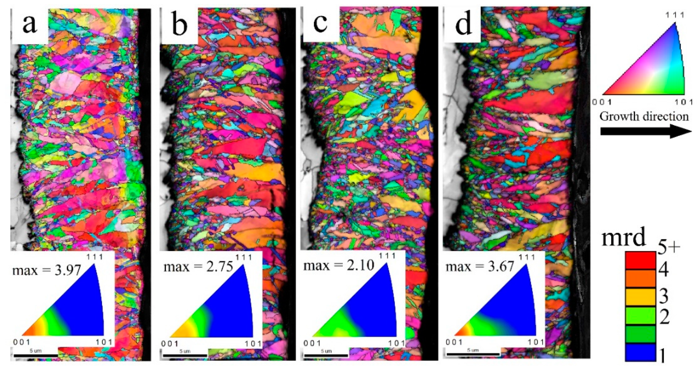
The average grain area values (GA), reported in Table 3, calculated from the EBSD maps (Figure 2), showed grain refinement in the composite metal microstructure, compared to pure Ni. The larger grain refinement was attributed to the inclusion of SiC particles. On the contrary, the grain refinement caused by graphite particles was limited. The presence of nano-SiC particles promoted nucleation overgrowth, with the particles acting as nucleation sites [26]. Ni-Graphite presented slightly smaller grain size values compared to nickel. Conducting large particles can promote nucleation overgrowth by providing a larger cathodic surface, but, due to the low content of graphite, their effect on grain refinement was limited. Ni-Dual maintained the same grain size as Ni-SiC, showing no synergy of the presence of both particles.
The surface roughness for all samples was alike (Ra ≈ 0.44 μm). Although Ni-SiC and Ni-Dual reported a decrease in grain size, their microstructure was dominated by large columnar grains also observed in pure Ni and Ni-Graphite (Figure 2). These large columns grew unaltered, imposing a similar surface roughness for all samples on a macroscopic level.
Ni-graphite composites showed islands of graphite aggregates on its surface, visible in secondary electrons’ (SE) and in-beam backscatter electron (BSE) imaging (Figure 3). These structures were comparable to the randomly disperse graphite agglomerates reported by Lapinski et al. [17] in Ni-Graphite composites, produced in a similar cell setup but with the addition of surfactants. Although Ni-Dual reported similar graphite content, there were no particle agglomerates on its surface. The incorporation of graphite in Ni-Dual was only possible by metal entrapment, observed as codeposited second phase (Figure 4a). In Ni-Graphite, graphite particles were not only limited at the coating surface but incorporated into the matrix as well (Figure 4b).
The EBSD maps in cross-section and the inverse pole figures are reported in Figure 2. The preferential growth for all composites was the <100> direction. This growth direction is typical of the so-called ‘free mode’ nickel crystal uninhibited growth [19], with large columns dominating the microstructure. Ni-SiC showed a decrease in the max intensity of the textured microstructure compared to pure Ni (Figure 2a). The addition of SiC particles encouraged an increase in the number of smaller particles by promoting nucleations’ sites, favoring a decrease in the number of large columns. The finer microstructure, built by randomly oriented smaller grains, led to a decrease in the max intensity in Ni-SiC and dual (Figure 2b,c). In contrast, graphite particles did not affect the texture intensity, reporting similar values to nickel (Figure 2a,d).

3.3. Microhardness

The microhardness tests showed a linear increase in hardness values linked to the decrease in average grain diameter (Figure 5). Pure Ni showed hardness values of about 280 HV. The codeposition of SiC particles caused an increase in the hardness values for both Ni-SiC and Ni-Dual. This increase in hardness was due to three factors: Hardness of the SiC particles, grain boundary strengthening, and dispersion strengthening [26,27]. As mentioned before, SiC particles promoted grain refinement. Thus, grain boundary strengthening was improved by the finer microstructure, in addition to dispersion strengthening by the SiC particles. The low volume fraction of SiC, similar in Ni-SiC and Ni-Dual, limited the particles’ strengthening. Rostami et al. [16] Ni-Dual samples showed a higher hardness (~550 HV). However, the reported content of SiC in their study was more than three times higher compared to the values in this study (Table 2). Previous studies [22,25,28,29] also reported higher hardness values compared to this study, in Ni-SiC composites with higher SiC content.
Graphite particles caused a minimal decrease in the average grain size compared to nickel (Table 2). Thus, marginally improving the grain boundary strengthening given by the microstructure. Therefore, Ni-Graphite hardness was similar to pure Ni. Due to the low content of graphite, both in Ni-Graphite and Ni-Dual, the inclusion of a softer second phase had no noticeable negative effect in hardness.

3.4. Tribological Study

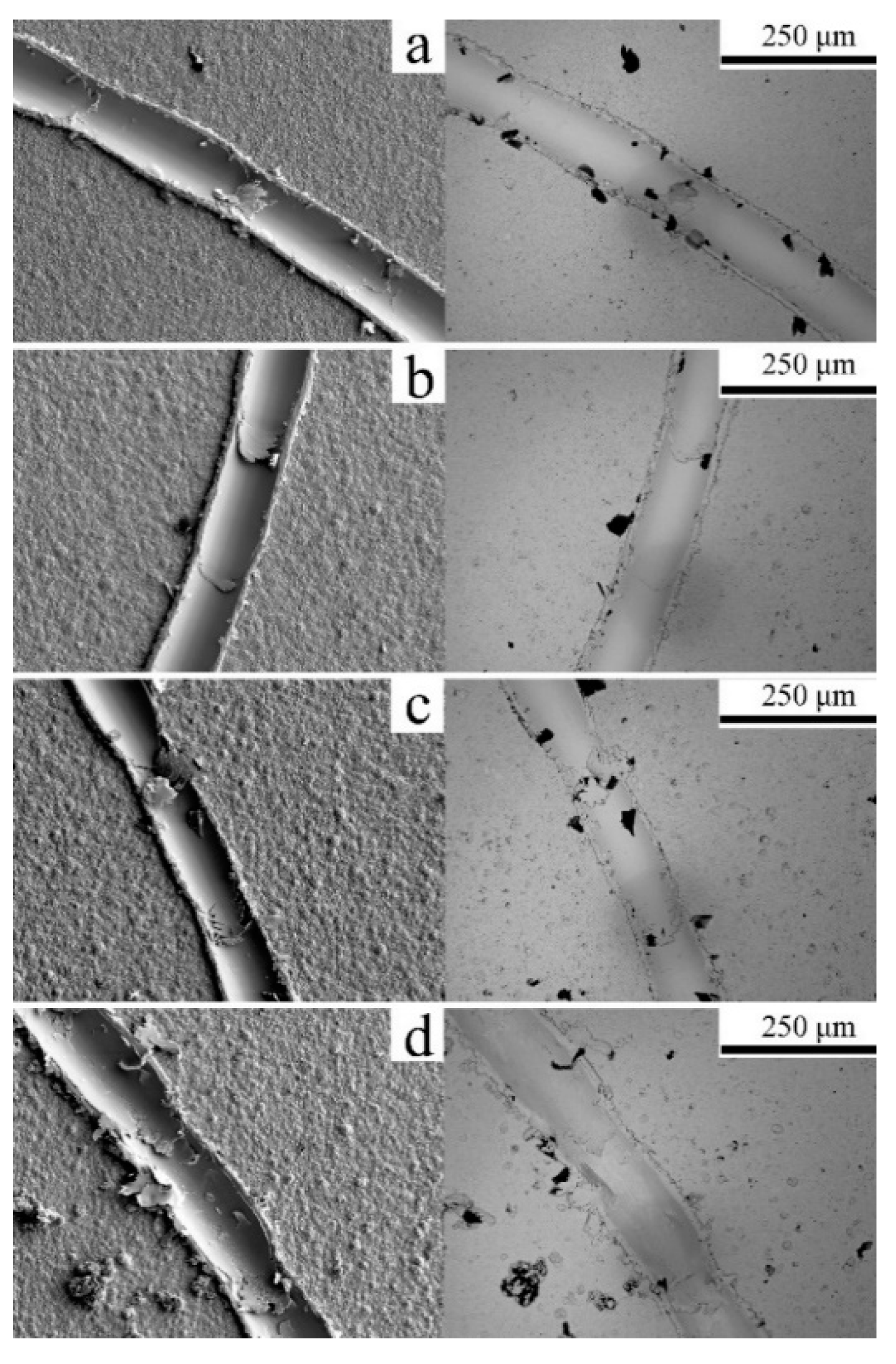
The average coefficients of friction (CoF) and volumetric wear are reported in Figure 6. The CoF were somewhat similar within a range between samples, remaining stable between the 0.1 and 0.2 with varying peak values indicating adhesive episodes. ‘Stick-slip’ behavior, associated with adhesive events [30], can be observed in the wear tracks (Figure 7) for all samples. Pure Ni and Ni-Graphite CoF showed slightly lower values compared to the composites with SiC, mono and dual. However, the CoF revealed no considerable difference between pure Ni and Ni-Graphite composite (Figure 5), showing no significant self-lubrication capability provided by the graphite due to the low content. SiC inclusion caused a minor increase in friction [31]. Ni-SiC and dual reported slightly higher CoF compared to pure Ni. The dual composite maintained similar CoF compared to Ni-SiC, showing no improvement in the presence of graphite as mix dispersion.
The wear tracks were similar for all samples (Figure 7). As previously mentioned, ‘stick-slip’ events were visible within the wear track. The appearance of the wear track indicated material ploughing by the counter material. In-beam BSE imaging showed nickel oxides, shown by the darker color [31,32], as debris in the pileup.
Ni-Graphite showed a slight improvement in the wear resistance compared to pure Ni. The addition of graphite provoked a minor decrease in grain size, thus increasing the deposits’ hardness. Therefore, the wear track profile (Table 4) showed a slightly diminished track, both in depth and width, resulting in a less worn volume (Figure 6). However, due to the low content and no self-lubrication capability provided by the graphite, the improvement was minimal.
Ni-SiC and Ni-Dual reported similar wear track profiles (Table 4), showing an improvement compared to pure Ni granted by the addition of SiC particles and the increase in hardness. The addition of graphite in Ni-Dual showed no improvement in the deposits’ wear resistance. Consequently, Ni-Dual reported similar volumetric wear as Ni-SiC (Figure 6).
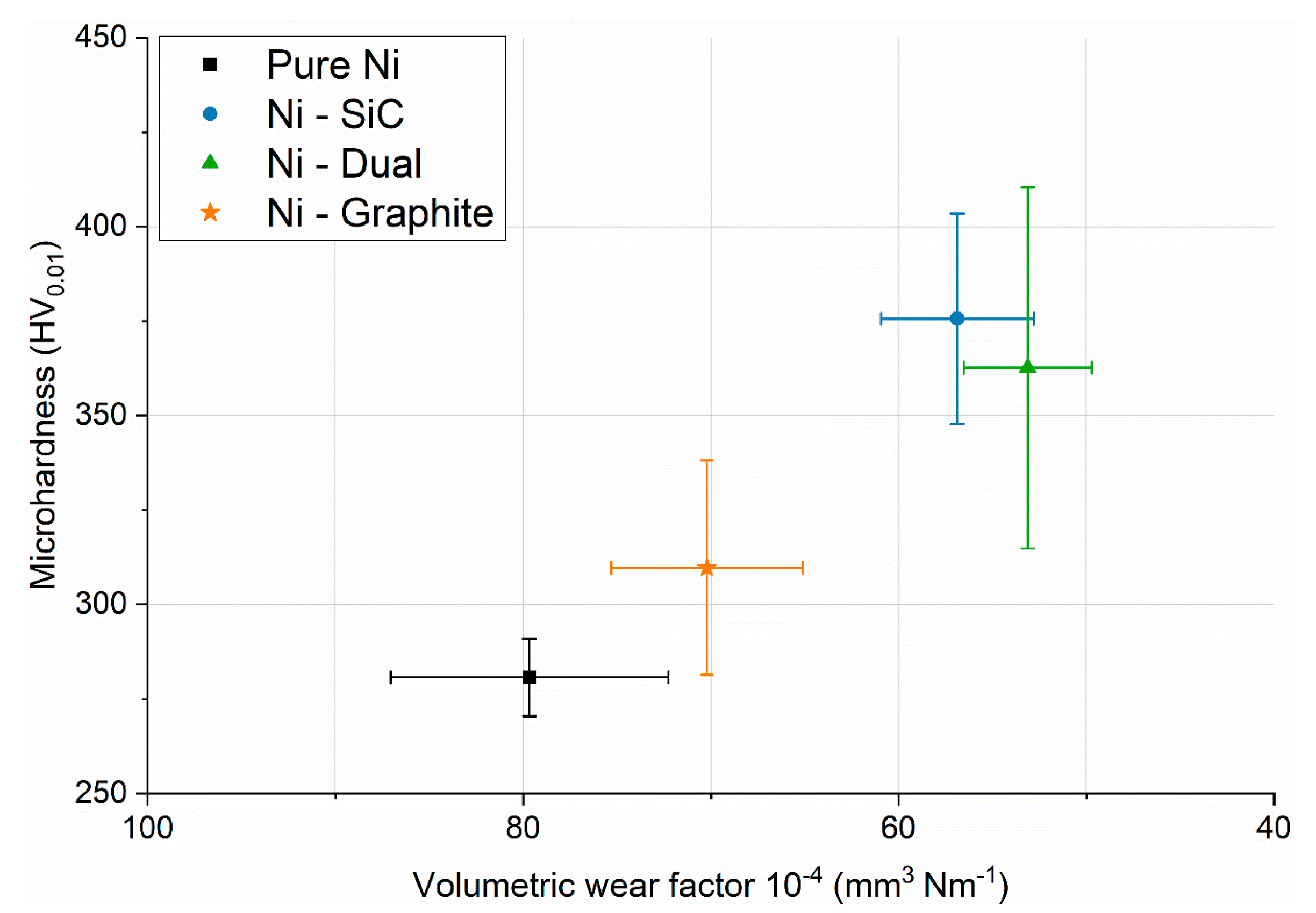
There was a linear relationship between the coatings’ volumetric wear factor and the microhardness (Figure 8). The worn volume decreased as the deposits’ hardness increased.
In the case of Ni-Graphite, the slight increase in hardness as the result of grain refinement decreased the volumetric wear factor compared to pure Ni. Moreover, the intensity of the apparent texture could be a weighing factor. The Ni microstructure corresponding to <100>, like the one reported in Figure 3 for pure Ni, had been associated with high ductility in pure nickel [13], favoring other crystallographic orientations, as the one resulted from graphite addition could improve the wear resistance. Gyftou et al. [31] also reported improvement in the wear resistance in Ni deposits with nondominant <100> microstructure.
SiC particle inclusion benefited the strengthening mechanisms, providing additional wear resistance [15,25], reporting a decrease in the volumetric wear factor in Ni-SiC and dual compared to both pure Ni and Ni-Graphite. The SiC nanoparticles promoted grain refinement, granting grain boundary strengthening in addition to particle strengthening. The addition of graphite in the dual composite did not provide the samples with further wear resistance. Therefore, the worn volume was comparable between samples with the same hardness.

4. Conclusions

The tribological analysis highlighted the relationship between wear resistance and composite hardness, i.e., worn material volume decreased when hardness increased. A synergistic effect between particle codeposition and strengthening mechanisms was determined to be the cause of the increase in hardness, therefore linking particle inclusion to wear resistance. Three main factors were determined to contribute to composites hardness: Intrinsic hardness of the reinforcement, strengthening by grain refinement, and dispersion strengthening.
The metal matrix benefited from particle inclusion by achieving a more refined microstructure. All particles encouraged nucleation overgrowth during nickel electrocrystallization, leading to smaller grain sizes. In the graphite composite, the particle effect was limited, leading to a slight decrease in grain size compared to pure Ni. The effect, although reduced, was sufficient to strengthen by grain boundary the microstructure, causing a slight increase in hardness and, thus, also decreasing the material volume worn by the pin-on-disc test compared to nickel. The content of graphite proved insufficient to provide a self-lubrication capability to the composite, reporting similar coefficients of friction to pure Ni. Therefore, the decrease in worn volume in Ni-Graphite was linked only to the increase in hardness caused by particle inclusion and resulting grain refinement.
Nano-SiC particles had a higher impact on the grain refinement compared to graphite, resulting in finer metal microstructures. In addition to the grain boundary strengthening, the matrix benefited from dispersion strengthening granted by the hard nano-sized carbides. Both Ni-SiC and Ni-Dual reported higher hardness values compared to pure Ni and Ni-Graphite, also showing better wear resistance. The presence of graphite in the SiC:Graphite dual powder mix had no impact on the codeposition of SiC nor provided additional benefits, such as self-lubrication capability, to the composites’ performance. Ni-SiC and dual reported similar codeposition, averaged grain sizes, hardness, and worn volume, therefore showing there was no synergy between powders.

Author Contributions

Conceptualization, S.P. and C.Z.; methodology, S.P. and C.Z.; validation, S.P. and C.Z.; formal analysis, S.P. and C.Z.; investigation, S.P.; resources, C.Z.; writing—original draft preparation, S.P.; writing—review and editing, C.Z.; visualization, S.P. and C.Z.; supervision, C.Z.; project administration, C.Z.; funding acquisition, C.Z. All authors have read and agreed to the published version of the manuscript.

Funding

This research was partially funded by Stiftelsen för Kunskaps- och Kompetensutveckling (Project FunDisCo; 20100280).

Conflicts of Interest

The authors declare no conflict of interest.

References

  1. Lekka, M.; Zanella, C.; Klorikowska, A.; Bonora, P.L. Scaling-up of the electrodeposition process of nanocomposite coating for corrosion and wear protection. Electrochim. Acta 2010, 55, 7876–7883. [Google Scholar] [CrossRef]
  2. Gyftou, P.; Pavlatou, E.A.; Spyrellis, N.; Hatzilyberis, K.S. Nickel matrix composite coatings: Application in textile machinery and evaluation of cotton products quality. Trans. IMF 2000, 78, 223–226. [Google Scholar] [CrossRef]
  3. Walsh, F.C.; Wang, S.; Zhou, N. The electrodeposition of composite coatings: Diversity, applications and challenges. Curr. Opin. Electrochem. 2020, 20, 8–19. [Google Scholar] [CrossRef]
  4. Donnet, C.; Erdemir, A. Historical developments and new trends in tribological and solid lubricant coatings. Surf. Coat. Technol. 2004, 180–181, 76–84. [Google Scholar] [CrossRef]
  5. Walsh, F.C.; Ponce de Leon, C. A review of the electrodeposition of metal matrix composite coatings by inclusion of particles in a metal layer: An established and diversifying technology. Trans. IMF 2014, 92, 83–98. [Google Scholar] [CrossRef] [Green Version]
  6. Kerr, C.; Barker, D.; Walsh, F.; Archer, J. The electrodeposition of composite coatings based on metal matrix-included particle deposits. Trans. IMF 2000, 78, 171–178. [Google Scholar] [CrossRef]
  7. Ortolani, M.; Zanella, C.; Azanza Ricardo, C.L.; Scardi, P. Elastic grain interaction in electrodeposited nanocomposite Nickel matrix coatings. Surf. Coat. Technol. 2012, 206, 2499–2505. [Google Scholar] [CrossRef]
  8. Lampke, T.; Wielage, B.; Dietrich, D.; Leopold, A. Details of crystalline growth in co-deposited electroplated nickel films with hard (nano)particles. Appl. Surf. Sci. 2006, 253, 2399–2408. [Google Scholar] [CrossRef]
  9. Zanella, C.; Lekka, M.; Bonora, P.L. Influence of the particle size on the mechanical and electrochemical behaviour of micro- and nano-nickel matrix composite coatings. J. Appl. Electrochem. 2009, 39, 31–38. [Google Scholar] [CrossRef]
  10. Góral, A. Nanoscale structural defects in electrodeposited Ni/Al2O3 composite coatings. Surf. Coat. Technol. 2017, 319, 23–32. [Google Scholar] [CrossRef]
  11. Borkar, T.; Harimkar, S.P. Effect of electrodeposition conditions and reinforcement content on microstructure and tribological properties of nickel composite coatings. Surf. Coat. Technol. 2011, 205, 4124–4134. [Google Scholar] [CrossRef]
  12. Gyftou, P.; Pavlatou, E.A.; Spyrellis, N. Effect of pulse electrodeposition parameters on the properties of Ni/nano-SiC composites. Appl. Surf. Sci. 2008, 254, 5910–5916. [Google Scholar] [CrossRef]
  13. Denise, F.; Leidheiser, H. An X-ray study of the effect of organic compounds on the crystal growth of nickel during electrodeposition. J. Electrochem. Soc. 1953, 100, 490–495. [Google Scholar] [CrossRef]
  14. Holmberg, K.; Ronkainen, H.; Laukkanen, A.; Wallin, K. Friction and wear of coated surfaces—scales, modelling and simulation of tribomechanisms. Surf. Coat. Technol. 2007, 202, 1034–1049. [Google Scholar] [CrossRef]
  15. Mahidashti, Z.; Aliofkhazraei, M.; Lotfi, N. Review of nickel-based electrodeposited tribo-coatings. Trans. Indian Inst. Met. 2018, 71, 257–295. [Google Scholar] [CrossRef]
  16. Rostami, M.; Fahami, A.; Nasiri-Tabrizi, B.; Ebrahimi-Kahrizsangi, R.; Saatchi, A. Characterization of electrodeposited Ni–SiC–Cg nanocomposite coating. Appl. Surf. Sci. 2013, 265, 369–374. [Google Scholar] [CrossRef]
  17. Lapinski, J.; Pletcher, D.; Walsh, F.C. The electrodeposition of nickel–graphite composite layers. Surf. Coat. Technol. 2011, 205, 5205–5209. [Google Scholar] [CrossRef]
  18. Watts, O.P. Rapid nickel plating. Trans. Am. Electrochem. Soc. 1916, 29, 395–403. [Google Scholar] [CrossRef]
  19. Amblard, J.; Epelboin, I.; Froment, M.; Maurin, G. Inhibition and nickel electrocrystallization. J. Appl. Electrochem. 1979, 9, 233–242. [Google Scholar] [CrossRef]
  20. Crouch, P.C.; Hendricksen, H.V. Current efficiency on Watts baths. Trans. IMF 1983, 61, 133–140. [Google Scholar] [CrossRef]
  21. Alizadeh, M.; Mirak, M.; Salahinejad, E.; Ghaffari, M.; Amini, R.; Roosta, A. Structural characterisation of electro-codeposited Ni–Al2O3–SiC nanocomposite coatings. J. Alloy. Compd. 2014, 611, 161–166. [Google Scholar] [CrossRef]
  22. Garcia, I.; Fransaer, J.; Celis, J.P. Electrodeposition and sliding wear resistance of nickel composite coatings containing micron and submicron SiC particles. Surf. Coat. Technol. 2001, 148, 171–178. [Google Scholar] [CrossRef]
  23. Nowak, P.; Socha, R.P.; Kaisheva, M.; Fransaer, J.; Celis, J.-P.; Stoinov, Z. Electrochemical investigation of the codeposition of SiC and SiO2 particles with nickel. J. Appl. Electrochem. 2000, 30, 429–437. [Google Scholar] [CrossRef]
  24. Hou, K.; Ger, M.; Wang, L.; Ke, S. The wear behaviour of electro-codeposited Ni–SiC composites. Wear 2002, 253, 994–1003. [Google Scholar] [CrossRef]
  25. Gül, H.; Kılıç, F.; Uysal, M.; Aslan, S.; Alp, A.; Akbulut, H. Effect of particle concentration on the structure and tribological properties of submicron particle SiC reinforced Ni metal matrix composite (MMC) coatings produced by electrodeposition. Appl. Surf. Sci. 2012, 258, 4260–4267. [Google Scholar] [CrossRef]
  26. Low, C.T.J.; Wills, R.G.A.; Walsh, F.C. Electrodeposition of composite coatings containing nanoparticles in a metal deposit. Surf. Coat. Technol. 2006, 201, 371–383. [Google Scholar] [CrossRef]
  27. Lanzutti, A.; Lekka, M.; De Leitenburg, C.; Fedrizzi, L. Effect of pulse current on wear behavior of Ni matrix micro-and nano-SiC composite coatings at room and elevated temperature. Tribol. Int. 2019, 132, 50–61. [Google Scholar] [CrossRef]
  28. Pinate, S.; Leisner, P.; Zanella, C. Electrocodeposition of nano-SiC particles by pulse-reverse under an adapted waveform. J. Electrochem. Soc. 2019, 166, D804–D809. [Google Scholar] [CrossRef]
  29. Vaezi, M.R.; Sadrnezhaad, S.K.; Nikzad, L. Electrodeposition of Ni–SiC nanocomposite coatings and evaluation of wear and corrosion resistance and electroplating characteristics. Colloids Surf. A 2008, 315, 176–182. [Google Scholar] [CrossRef]
  30. Berman, A.D.; Ducker, W.A.; Israelachvili, J.N. Experimental and theoretical investigations of stick-slip friction mechanisms. In Physics of Sliding Friction; Persson, B.N.J., Tosatti, E., Eds.; Springer: Dordrecht, The Netherlands, 1996; pp. 51–67. ISBN 978-90-481-4674-1. [Google Scholar]
  31. Gyftou, P.; Stroumbouli, M.; Pavlatou, E.A.; Asimidis, P.; Spyrellis, N. Tribological study of Ni matrix composite coatings containing nano and micro SiC particles. Electrochim. Acta 2005, 50, 4544–4550. [Google Scholar] [CrossRef]
  32. Kato, K. Abrasive wear of metals. Tribol. Int. 1997, 30, 333–338. [Google Scholar] [CrossRef]
Figure 1. Secondary electrons’ image of surface topography: (a) Pure Ni; (b) Ni-SiC; (c) Ni-Dual; (d) Ni-Graphite.
Coatings 10 01060 g001
Figure 2. Orientation map, color-coded in relation to the electrodeposits’ growth direction, shown by an arrow in the figure, and the equivalent inverse polar figure, including the max texture intensity in units of multiplies of random distribution (mrd) as indicated by the color bar. (a) Pure Ni; (b) Ni-SiC; (c) Ni-Dual; (d) Ni-Graphite.
Coatings 10 01060 g002
Figure 3. Ni-Graphite surface image: (a) SE; (b) corresponding in-beam BSE.
Coatings 10 01060 g003
Figure 4. Cross-section image: (a) Ni-Dual; (b) Ni-Graphite. Graphite particles are indicated by the white-colored circles.
Coatings 10 01060 g004
Figure 5. Microhardness vs. average grain diameter measured for the electrodeposited pure Ni and Ni-composites.
Coatings 10 01060 g005
Figure 6. Average coefficients of friction (CoF) and volumetric wear factor (mm3 Nm−1).
Coatings 10 01060 g006
Figure 7. SE and in-beam BSE image of the wear tracks: (a) Pure Ni; (b) Ni-SiC; (c) Ni-Dual; (d) Ni-Graphite.
Coatings 10 01060 g007
Figure 8. Microhardness vs. volumetric wear factor (mm3 Nm−1) for the electrodeposited pure Ni and Ni-composites.
Coatings 10 01060 g008
Table 1. Electroplating bath composition and parameters.
Bath Compositionsg L−1Parameters
NiSO4·7H2O (Sigma-Aldrich)240 pH 3.00
NiCl2·6H2O (Sigma-Aldrich)45 Temperature45 °C
H3BO3 (J.T. Baker)30 Stirring 200 rpm
Particle load10; 10:10Current density4 A dm−2
--Deposition time30 min
Table 2. SiC and graphite codeposited volume and weight content (%) as determined by WDS.
Particle ContentSiCDualGraphite
SiCGraphite
Vol%1.58 ± 0.481.45 ± 0.515.32 ± 1.503.99 ± 0.48
Wt%0.58 ± 0.180.55 ± 0.201.41 ± 0.421.03 ± 0.13
Table 3. Deposits’ average grain area (GA, μm2).
SamplePure NiNi-SiCNi-DualNi-Graphite
Grain area8.14 ± 0.336.55 ± 0.416.42 ± 0.307.86 ± 0.40
Table 4. Wear track profile, track width (μm), and track depth (μm).
Track ProfilePure NiNi-SiCNi-DualNi-Graphite
Width95.18 ± 4.4289.91 ± 3.9989.49 ± 2.3492.14 ± 3.19
Depth12.35 ± 0.789.88 ± 0.569.37 ± 0.4111.20 ± 0.39
Publisher’s Note: MDPI stays neutral with regard to jurisdictional claims in published maps and institutional affiliations.