Article

Processing of Spark Plasma Sintered Fe Alloy and Enhancing Its Surface Properties by AlCrN Monolayer Coating by Cathodic Arc Plasma Physical Vapor Deposition Process

1
School of Mechanical Engineering, Vellore Institute of Technology, Vellore Campus, Vellore 632014, India
2
Centre for Innovative Manufacturing Research, Vellore Institute of Technology, Vellore 632014, India
3
Department of Mechanical Engineering and Advanced Institute of Manufacturing for High-Tech Innovations, National Chung Cheng University, Chia-Yi 62102, Taiwan
*
Author to whom correspondence should be addressed.
Equally contributed as the First Author.
Coatings 2020, 10(12), 1166; https://doi.org/10.3390/coatings10121166
Submission received: 12 October 2020 / Revised: 25 November 2020 / Accepted: 27 November 2020 / Published: 28 November 2020
(This article belongs to the Special Issue Surface Plasma Treatments)

Abstract

:
The current investigation observes the outcome of enhancing the surface properties by AlCrN monolayer coating using the cathodic arc plasma method on the Fe–Cu–C–Mo alloys. The compacts were sintered in spark plasma sintering (SPS) with the heat transfer rate of 100 °C/min at 1120 °C for 5 minutes. The Fe–2Cu–0.8C–0.6Mo sample has the highest relative sintered density (97.20%), hardness (96 HRB), and ultimate tensile strength (1000 MPa) compare with the other sintered compacts. AlCrN coating was deposited on Fe, Fe–2Cu, Fe–2Cu–0.8C, Fe–2Cu–0.8C–0.2Mo, Fe–2Cu–0.8C–0.4Mo, and Fe–2Cu–0.8C–0.6Mo samples, using the cathodic arc plasma–physical vapor deposition (CAP-PVD) process. The coated compact samples’ metallography images were examined using a Scanning Electron Microscope (SEM); the Fe–2Cu alloy sintered sample has obtained a uniform structure with high density and a smaller amount of corrosion penetration rate (0.6579 mmpy) as compared to the counterparts. The phase formed in the AlCrN coating was analyzed using the X-ray Diffraction (XRD). The Fe–2Cu–0.8C–0.6Mo coated compact sample exhibited higher hardness (1134.85 HV0.3) than the other coated compact samples. The Fe–2Cu–0.8C–0.2Mo coated compact sample has proven better corrosion resistance compared to the other coated compact sample.

1. Introduction

Pure iron is soft and ductile. The alloying elements such as copper, chromium, nickel, graphite (C), and molybdenum are added in iron to enhance the mechanical properties such as strength, corrosion resistance, wear-resistance, and hardness. During the sintering process, copper atoms diffuse slowly in iron powder, form swelling (copper growth), and form a solid solution. The graphite is further added to iron to enhance the strength, hardness by forming a pearlite structure and to control the swelling of copper. The tensile property indicates cup and cone fracture for Fe–Cu and Fe–Cu–C alloys. The production cost is low, and close dimensional accuracy can be maintained for these alloys. Hence it is mostly used in automotive applications [1]. The products produced by the powder metallurgy technique are widely used due to the easy formation of complicated shapes and saving manufacturing time. A heat-treatment process can obtain the high hardness of the sintered component. Copper and carbon are further added as alloying elements to improve the strength of the powder metallurgical components. The components sintered temperature is rapidly decreased to have considerable microstructure transformation to increase the hardness and reduce the sintered parts’ porosity. A tempering process can reduce the internal stresses of the sintered parts. The compaction pressure and sintering temperature play a significant role in the sintering process [2]. The microwave sintering is adopted for powder compacts to enhance the microstructure from coarse to refined grains by the rapid heating process. The micro or macro cracks have not been observed in the microstructure of the microwave sintered components. The hardness can be improved further in the microwave sintering process than the conventional process, and the processing time can be reduced to 60% [3]. The powder metallurgical parts are subjected to the sinter-hardening process to reduce the processing time and cost. The alloys present in the iron powder diffuse and increase the sintered compacts’ strength and toughness by increasing the compaction pressure and sinter density. The sintered compacts’ mechanical properties can be improved by the hardening and tempering process [4]. The P/M alloys have performed better by adding alloying elements such as Ni, Mo, Cu, and Mn. These alloying elements increase the hardenability by shifting the nose to the TTT (time-temperature transformation) curve’s right side, allowing the ease of hardenability, thereby allowing martensite formation at slower cooling rates. The copper is the essential alloying element in the powder metallurgy technique, which increases the strength sufficiently. The mixing of carbon and copper with pre-alloyed iron increases the number of sintered components for automotive applications. The increase in hardenability and compressibility improves the components’ mechanical properties and density due to alloying elements [5,6]. The 2% of copper shows liquid copper precipitates at the grain boundaries, increases the swelling effect during the sintering process, and increases the hardness because of precipitation hardening and solid solution. The fast rate of heating and cooling in the microwave sintering process forms refined grains in the microstructure. The cavities or pores are significantly less in the microwave sintering process due to the broad area of metal contact [7]. Graphite, when added with Fe–Cu alloy, acts as a barrier for Cu in grain boundary penetration. The graphite atoms distribute homogeneously into the Fe matrix during the sintering process because the diffusion rate was higher. The tensile and yield strength of iron increases by adding copper and carbon. The pearlite structure is formed due to the presence of carbon atoms. The Fe–Cu alloy has shown higher densification and uniform microstructure due to the compacts’ sintering effect [8].
Corrosion is the major problem for metal and alloys. To increase the corrosion resistance of a material, different types of coating methods are using like laser cladding [9], electro-spark deposition [10], magnetron sputtering [11], etc. M. Carboneras et al. for the powder metallurgy processed magnesium protected by MgF2 layer, using the chemical conversion method MgF2 layer is formed on the Magnesium surface [12]. L. Pezzato et al. conducted another study on how the corrosion resistance film depends on the substrate’s manufacturing process. Their study concluded that the plasma electrolytic oxidation coated selective laser melted alloy was less porous than the casted alloy [13]. Physical vapor deposition is one of the methods adopted commonly to improve the steel substrate’s surface qualities. The surface qualities such as wear resistance, corrosion resistance, strength, hardness, smooth surface, and refined grains can be obtained by PVD coating. TiN coating obtained on 100Cr6 steel substrate has higher wear resistance due to high adhesion strength. These coatings are produced with a hard and dense structure to enhance surface topography [14]. The PVD coatings act as a protective layer over the metal surfaces such as nitrides, carbides, and metal oxides to improve the mechanical, corrosion, and wear properties. The aerospace, machinery, and automotive industries focus on PVD coatings with high hardness and high strength. The CrN coating was deposited on stainless steel (SUS304), and the microstructure, phase formations, and corrosion studies were investigated. The results showed that the microstructure with fewer pores, the phase analysis with various CrN peaks, high corrosion resistance due to the reduction in the average grain size of CrN coating [15].
The TiCN coating layer was deposited on stainless steel 316L using the PVD process. The corrosion and wear studies were conducted on the coated substrates. The results have proven that the corrosion and wear resistance is higher for TiCN coated samples. The TiCN coated sample phase analysis indicates that the NaCl Cubic FCC (Face Centered Cubic) structure. The TiN and TiC structures were obtained with sufficient adhesion strength with the base material [16]. The two types of chromium coatings such as 1. Cr2N (20%) & Cr (80%) and 2. CrN was obtained on S.S. (Stainless steel) 316 L by varying the nitrogen gas flow rate.
The corrosion test was carried for the S.S. 316 L coated samples. The results have shown that the CrN coating obtained on S.S. 316 L has higher corrosion resistance due to lesser interfacial contact resistance than the other coated samples [17]. S. Zhang et al. illustrated that AlCrN coating is better corrosion resistance than the TiN based coatings [18]. The pure Fe, Fe–2Cu, Fe–2Cu–0.8C, Fe–2Cu–0.8C with varying weight percentages (0.2%, 0.4%, and 0.6%) in the present work molybdenum compositions compacts were fabricated by using a spark plasma sintering process. Their mechanical properties for the parent materials were studied and reported. The current literature evidences the significance of AlCrN coating on Fe–Cu alloys to improve the surface properties. In the present study, the cathodic arc plasma–physical vapor deposition (CAP-PVD) process was used to deposit AlCrN coating on the parent materials. The corrosion rate of the sintered compacts before and after the coating was investigated. The characteristics of AlCrN coating were analyzed and assessed for its suitability for automotive applications.

2. Experimental

2.1. Sintering Process

The SEM images of the carbonyl Fe, Copper, Graphite, and Molybdenum powders are shown in Figure 1. The microstructures of the as-sintered samples were shown in Figure 2. The carbonyl Fe has obtained nano circular powder particles with high density and uniform structure. The graphite powder has obtained irregular flake particles, as shown in the SEM image. The characteristics of carbonyl Fe, copper, graphite, and molybdenum powders are shown in Table 1. The powders were then consolidated by employing a DR. Sinter 21,050 SPS furnace. In SPS technology, a conductive die is taken, into which powdered material is loaded. Uniaxial pressure (30 MPa) is applied, and at the same time, a pulsed electric current of voltage (4–20 V) and amperage (0.5–20 kA) is supplied through the die. The sintering temperature was monitored by making use of a thermocouple. The sintering temperature and time were set as 1120 °C and 5 min respectively in a vacuum chamber to prepare the compacts, and then it was kept for furnace cooling. The SPS furnace was maintained with a vacuum pressure of 2 Pa. The spark plasma generated in the furnace was used to increase the powder compact’s hotness with a 100 °C/min heating rate. The temperature was measured using a K-type thermocouple. The metallography, tensile, and hardness samples were obtained from solid circular disks formed by the spark plasma sintering process, and the cutting operation is performed using EDM wire-cut.
The Archimedes measurements technique was employed to measure density after sintering. A metallurgical microscope was used to obtain the surface morphology of the sintered samples. Silicon Carbide emery sheets of 220, 320, 500, 800, and 1000 were used to burnish the samples. Cloth polishing techniques was further adopted by making use of a suspension of 0.05 μm Al2O3 mixed with H2O. Then, the sample surfaces were subjected to microstructural analysis by employing a DM2500 Leica optical microscope (Leica Microsystems, Mumbai, India). The etching was carried out with a 5% initial solution. For the tensile testing, micro tensile samples are prepared with EDM according to the ASTM-E8 standards [19]. The tensile test is conducted in the universal testing machine (Instron 8801, University Ave Norwood, Norwood, MA, 02062-2643, USA) of full-load 20 kN at an initial strain rate of 3.3 × 10⁻⁴·s−1. To obtain the average value, five sample trails were tested and reported. The Rockwell hardness tester (Technofine Equipment, Model: TRSN-D, Kolkata, India) with a 16-inch ball indenter was used, and a load of 100 kg was applied to obtain the bulk hardness of the sintered compact on an HRB scale.
The powders’ microstructure, tensile fracture surface, and coating characteristics were analyzed using a Scanning Electron Microscope (Model: Research-EVO-18, Carl Zeiss, Jena, Germany) with EDAX. The Fe–Cu coated samples’ micro-hardness was measured using the Vickers’s micro-hardness tester-Matsuzawa Instruments, (Model: MMT-X, Matsuzawa Co., Ltd. 120-19, Aza-Nanamagaridai, Toshima, Kawabe, Akita-shi, Akita Pref, 019-2611, Japan) of 10 s as dwell time. The XRD analysis was conducted using a Powder X-ray Diffractometer (Model: Advance-D8-BRUKER, Kolkata, India). The corrosion test was studied by employing the potentio-dynamic polarization testing apparatus (Technologies Advanced electrochemical system-IVIUM) (Model: Version 54800, AJ Eindhoven, The Netherlands). In this corrosion testing method, three electrodes were used, such as (1) the working electrode (the coated test samples were exposed to 1 cm2 square area), (2) Platinum counter electrode, and (3) Saturated Calomel Electrode (SCE) as reference electrode was utilized to conduct the electrochemical corrosion testing. The working electrode was immersed for 30 min in the corrosive medium to obtain the open circuit potential (OCP) under steady-state conditions earlier to each electrochemical process. The AlCrN monolayer coated Fe–Cu alloy samples were investigated using a potentiodynamic polarization technique at average room temperature with a 3.5% NaCl solution to obtain the corrosion resistance. The Tafel curve parameters are a scan rate of 10 mV/s, scan area of 1 cm2, and potential range of −1.444 to +0.556 V.

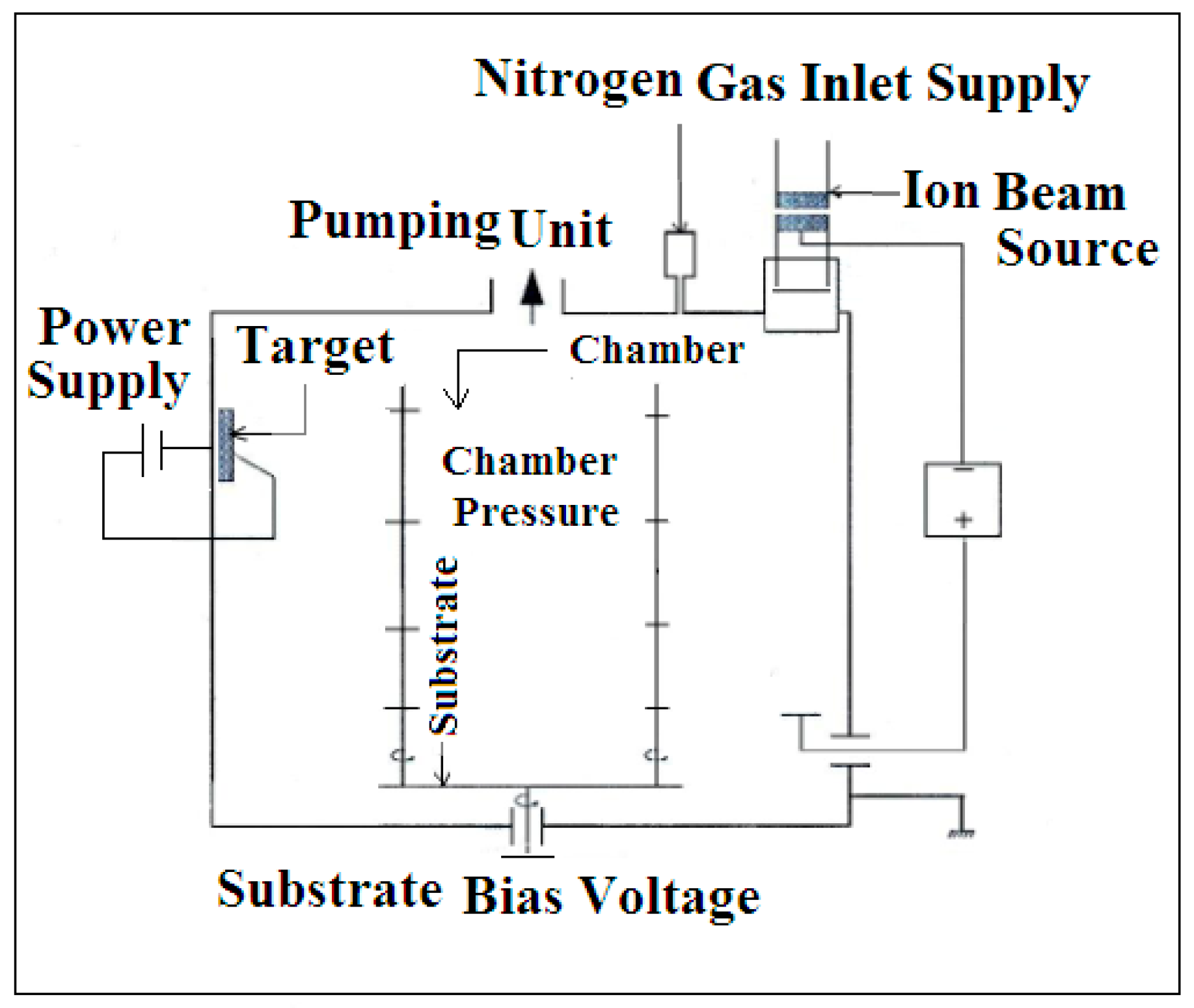
2.2. Coating Process

A standard Oerlikon Balzer’s coating equipment was used for the cathodic arc plasma–physical vapor deposition (CAP-PVD) process. The outline diagram of the CAP-PVD system is shown in Figure 3. The customized sintered circular targets material of 70 at.% Al and 30 at.% Cr were located inside the compartment during the AlCrN monolayer coating process [20]. The details of the AlCrN monolayer coating process parameters are shown in Table 2. Before AlCrN deposition, all the Fe–Cu alloy samples were cleaned with an ultrasonic cleaning machine and heated with hot air to remove the moisture content. The cleaning process was 1.4 h.
The hard coating was obtained by plasma reaction, assisted by the reactive gases N2 throughout the coating practice. The N2 gas was quickly decomposed, and the reaction occurred in the plasma region, which forms the ionized metal ions, as hard thin films on the substrate surface. The CAP-PVD process is stable without oxidation using the inert environment bypassing the Ar gas into the coating compartment. The Ar and N2 gas pressures are set based on the chamber pressure. The sample temperature was measured before deposition, using K–type thermocouple placed near the sample and maintained at 400 °C with temperature sensors. Throughout the CAP-PVD method, 150 A was set as a substrate current, and 30 V was set as a bias voltage.

3. Result and Discussions

3.1. Sintered Compacts Analysis

3.1.1. Density Analysis

The apparent density is less for graphite, and it is higher for Fe. The Cu and Mo element has obtained moderate density. The effect of varying alloying addition on the densification response of carbonyl iron powder compacts sintered in spark plasma heating furnace was shown in Table 3. The addition of graphite and increasing in Mo element % in Fe increases the sintered compact density. Pure iron has 90.18% relative sintered density; the highest sintered density (97.20%) is observed with the Fe–2Cu–0.8C–0.6Mo sample. With an increase, the Mo content from 0.2–0.6% in the Fe–2Cu–0.8C sample relative sintered density gradually increased. For densification, Cu is also playing a pivotal role. Copper melting point (1083 °C) below the sintering temperature, during the sintering copper, melts and penetrates the voids between the Fe-Fe particles and Fe other powder particles; this is attributed to the increasing in the sintered density [21]. If the copper content is high, the copper melt has a transient nature, so there is a chance to form secondary pores. It decreases the density [20], to reduce the swelling behavior of copper graphite is added [22]. However in the case of spark plasma sintering, uniaxial pressure is continuously being applied it is not giving a high chance to expand the copper, so the density is increased. Figure 3 shows the optical microstructure of all the sintered alloys. In Figure 3a,b, pearlite is not formed only in the graphite contain alloys pearlite is formed. Mo acts as the grain refiner, and its influence to increase the tensile strength [23].

3.1.2. Hardness Analysis

The Rockwell hardness values of spark plasma sintered alloys were shown in Table 4. Addition of the 2 wt.% copper to the iron showing in the increment (45 to 47 HRB) of hardness due to the increase in the sintered density. Addition of the carbon in the form of graphite showing a high impact on the hardness. The addition of graphite and increasing in Mo element % in Fe improves the sintered compact’s hardness. Mo acts as the grain refiner, and it improves the hardness of the material [24]. The highest hardness (96 HRB) is obtained for the Fe–2Cu–0.8C–0.6Mo alloy.

3.1.3. Tensile Test Analysis

The effect of alloying addition on the tensile properties of carbonyl iron compacts was shown in Table 5. The percentage of the elongation is increased with the addition of the Cu to the Fe. Cu has higher slip systems compare with Fe, so it influences the plastic deformation of the material. The addition of graphite and increasing in Mo element % in Fe improves the UTS of the sintered compacts. SEM fractography of the tensile test was shown in Figure 4. In Figure 4a Fe fractography of the surface, two types of fracture surface (ductile and brittle) are observed. In Figure 4b Fe–Cu fracture surface is the maximum ductile fracture surface is observed because of the copper addition effect. With the addition of the graphite to the Fe–Cu dimples and river, patterns are noticed. Not only fracture surface tensile test results also show the elongation decrease with the addition of the C. When Mo is added to the Fe–Cu–C area, the ductile fracture decreases, and the brittle fracture surface area increases. In Figure 4f Fe–2Cu–0.8C–0.6Mo alloy fractography is showing the brittle type of fracture surface. Increasing the Mo content strength of the material increases, it influences the ductile type fracture surface and is converted to the inter-crystalline and trans-crystalline fracture [25].

3.1.4. Corrosion Analysis

The potentiodynamic polarization corrosion testing machine was used to obtain the corrosion rate following the standard ASTM G59-97 is used [24]. The corrosion current (Icorr) and corrosion potential (Ecorr) are shown in Figure 5, representing the potentiodynamic polarization curves of the carbonyl iron powder compacts sintered samples. Rp (Polarization resistance), Ecorr (Corrosion potential), icorr (Corrosion current density), and C.R. (Corrosion rate) values attained from the potentiodynamic polarization studies for carbonyl iron powder compacts sintered samples were shown in Table 6.
The icorr value (0.0002011 A/cm2) of the Fe–2Cu coated sample indicates a reduced corrosion current than the other samples. A similar type of tendency has been observed in the polarization analysis. The Fe–2Cu sample has attained a reduced corrosion rate of 0.6579 mmpy. The pure Fe sample has obtained more corrosion current (0.000825 A/cm2) and a greater corrosion rate of 2.7 mmpy. The Fe–2Cu sample has shown improved corrosion resistance while compared with the remaining samples. The reduction in icorr indicates the enhancement in the corrosion resistance (corrosion rate declines) [26]. It is confirmed from the icorr and Rp values obtained in Table 6 [27,28].

4. Coating Characterization

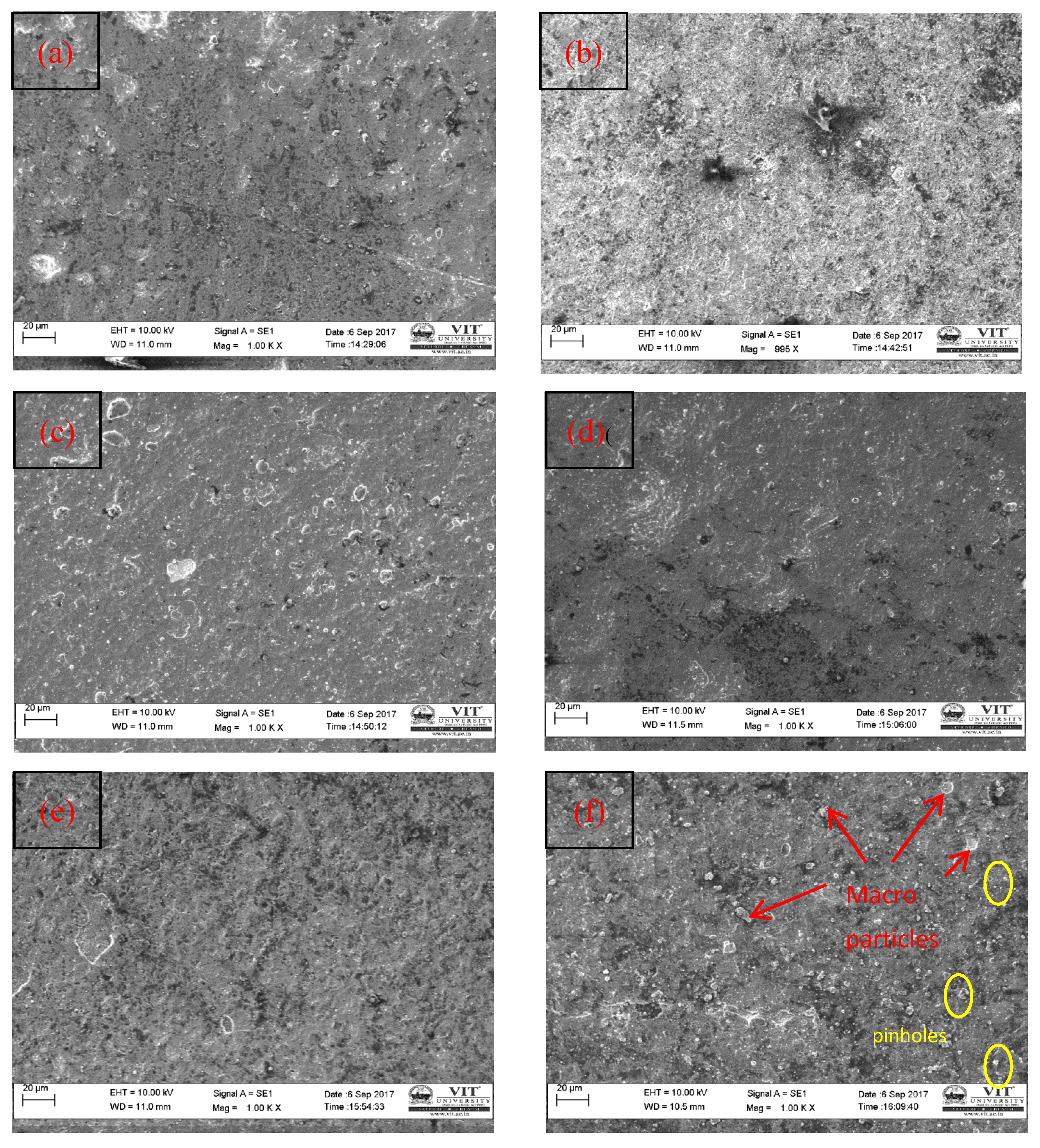
4.1. SEM Investigation

The microstructure of the AlCrN monolayer coating deposited on Fe and Fe–2Cu alloys is shown in Figure 6 and Figure 7. The coating thickness obtained for the AlCrN coating was 5 ± 2 µm. The coating’s cross-sectional observation confirms that the AlCrN monolayer coating obtained above the substrate, and the SEM photomicrograph shows that the AlCrN monolayer is adequately bonded with the substrates. The SEM photomicrograph of the AlCrN monolayer coating displays a thick structure with an uneven surface with has fewer macroparticles (marked in Figure 7f), tiny pores, and microcavities due to the occurrence of droplets and lumps. Microparticles are the one type of defect linked to the limited technology of the coating process. Micron sized cathode droplet spill off from the cathode spot. The high-pressure collisions between atoms, even before deposition on the substrate surface, promote agglomerates formation [29].
The elemental compositions of the coated samples were shown in Table 7. The thick structure of the coating enhances the hardness of the coated surface [30,31,32].

4.2. XRD Analysis

The X-ray Diffraction peaks of the AlCrN monolayer coating obtained by the cathodic arc plasma–physical vapor deposition (CAP-PVD) process is graphically represented in Figure 8. The maximum peaks in the 2θ ranges from 37° to 47° and 78° to 85° resemble the CrN and AlN patterns [33]. The AlCrN monolayer coating reveals a different pattern for the CrN and AlN films with different orientations [19,20]. The intensities are gradually reduced, specifying that the particle size’s plodding declines and flagging to the preferred orientation, indicated by the diffraction peaks. The AlN (101), CrN (102), AlN (102), CrN (220), AlN (202), AlN (104), and CrN (200) planes have attained the maximum peak with cubic structure [34,35]. The Scherrer equation (Dp = 0.94 λ/β·cosθ) was used to determine the crystallite size (Dp) for the AlCrN monolayer coating, which ranges from 35 to 58 nm [36,37,38].

4.3. Microhardness Analysis

The micro Vickers’ indentation load of 0.3 kgf and dwell of 10 s was applied on AlCrN coating. The penetration load was gradually increased after the indenter tip’s primary contact on the coated top surface. The test method is IS 1501-2002 [39]. The measurement is taken for eight trials, and their mean values were reported in Table 8. The outcomes specify that the AlCrN monolayer coating has obtained higher hardness (1134.85 Hv0.3) for Fe–2Cu–0.8C–0.6Mo substrate compared to the other samples. Thus, the coating’s metallurgical performance strongly influences the grain structure and the hardness [40].

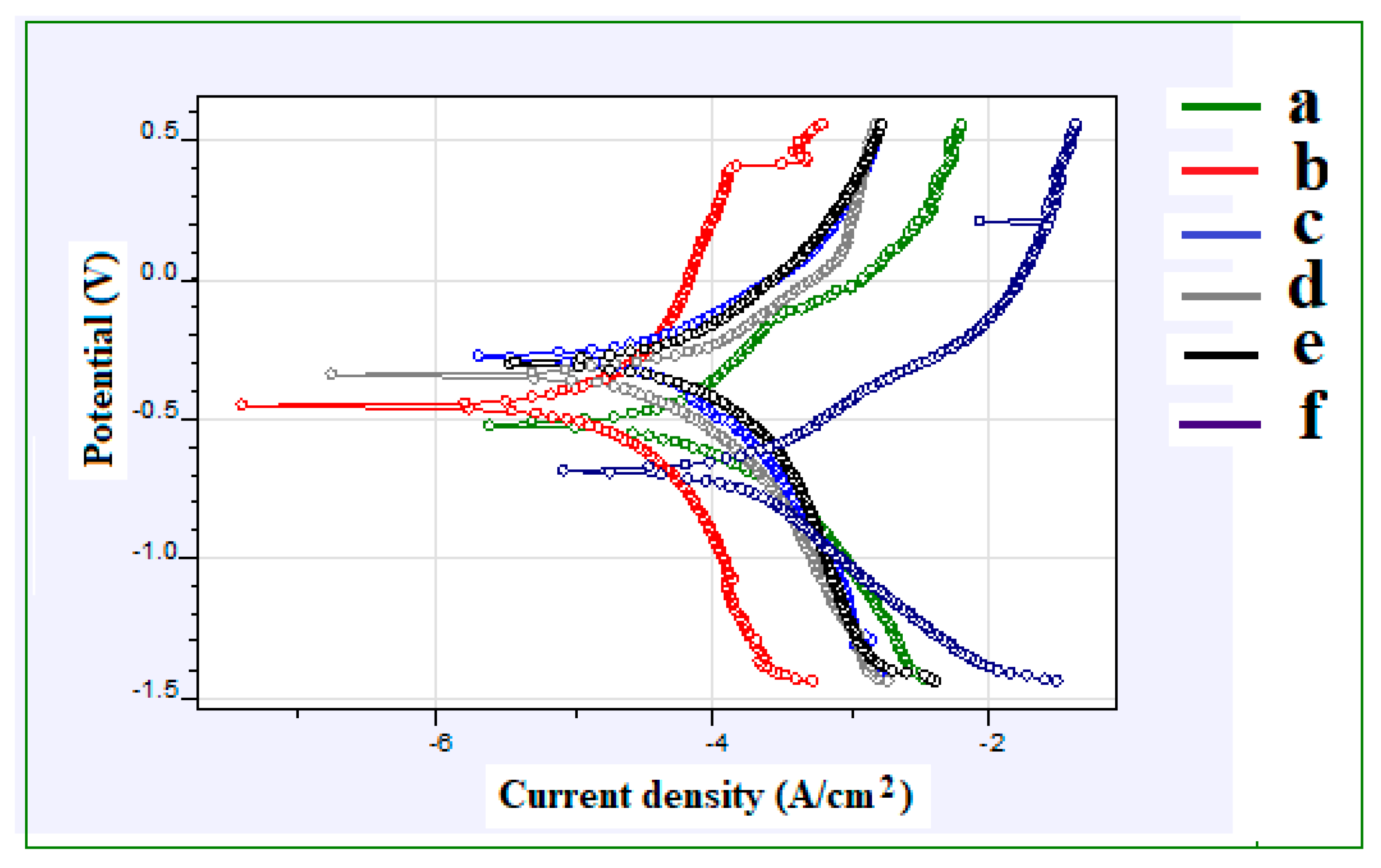
4.4. Corrosion Analysis

The potentiodynamic polarization curves obtained for AlCrN monolayer coated samples were shown in Figure 9. The potentiodynamic polarization data obtained from the electrochemical corrosion test is shown in Table 9. The icorr value is obtained as 0.00002539 A/cm2 for Fe–2Cu–0.8C–0.2Mo coated sample shows the reduced corrosion current than the other coated samples. The corrosion rate of 0.08306 mmpy was observed for Fe–2Cu–0.8C–0.2Mo coated sample. The Fe–2Cu–0.8C–0.6Mo coated substrate has shown a more significant corrosion current (0.00008557 A/cm2) and a larger corrosion rate of 0.28 mmpy. The Fe–2Cu–0.8C–0.2Mo coated sample has evidenced better corrosion resistance while related to the remaining coated substrates. It was evident from the polarization resistance and corrosion current density according to the results attained in Table 8. The decline in icorr permits the corrosion resistance (corrosion rate decreases) [28,40].

5. Conclusions

The Fe with varying the weight percentage of the copper (Cu), graphite (C), and molybdenum (Mo) 6 alloys were prepared using a spark plasma sintering process, and the mechanical properties were studied and reported. AlCrN monolayer coating was deposited on the sintered compact samples, using the CAP-PVD process, electrochemical corrosion resistance of the Fe alloys with and without coating was investigated, the following conclusions are made:
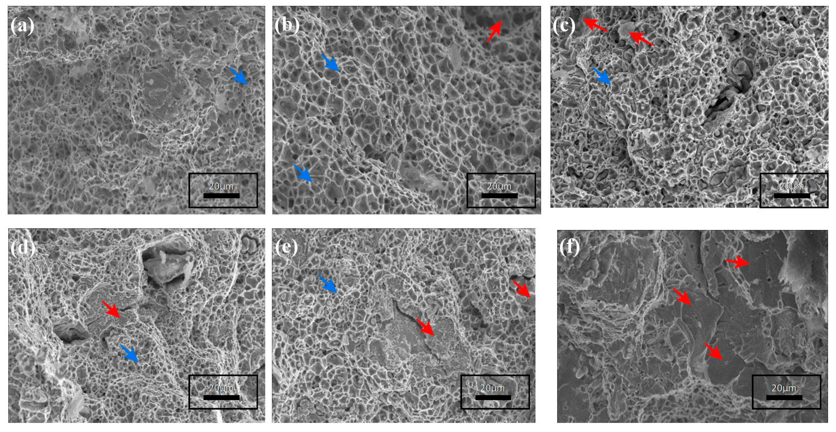
  • A Fe–2Cu–0.8C–0.6Mo compact sample has obtained a higher relative sintering density of 97.20%, high hardness of 96 HRB, and high ultimate tensile strength of 1000 MPa compared with the other sintered compacts. The SEM fractography shows both ductile and brittle type fracture surfaces.
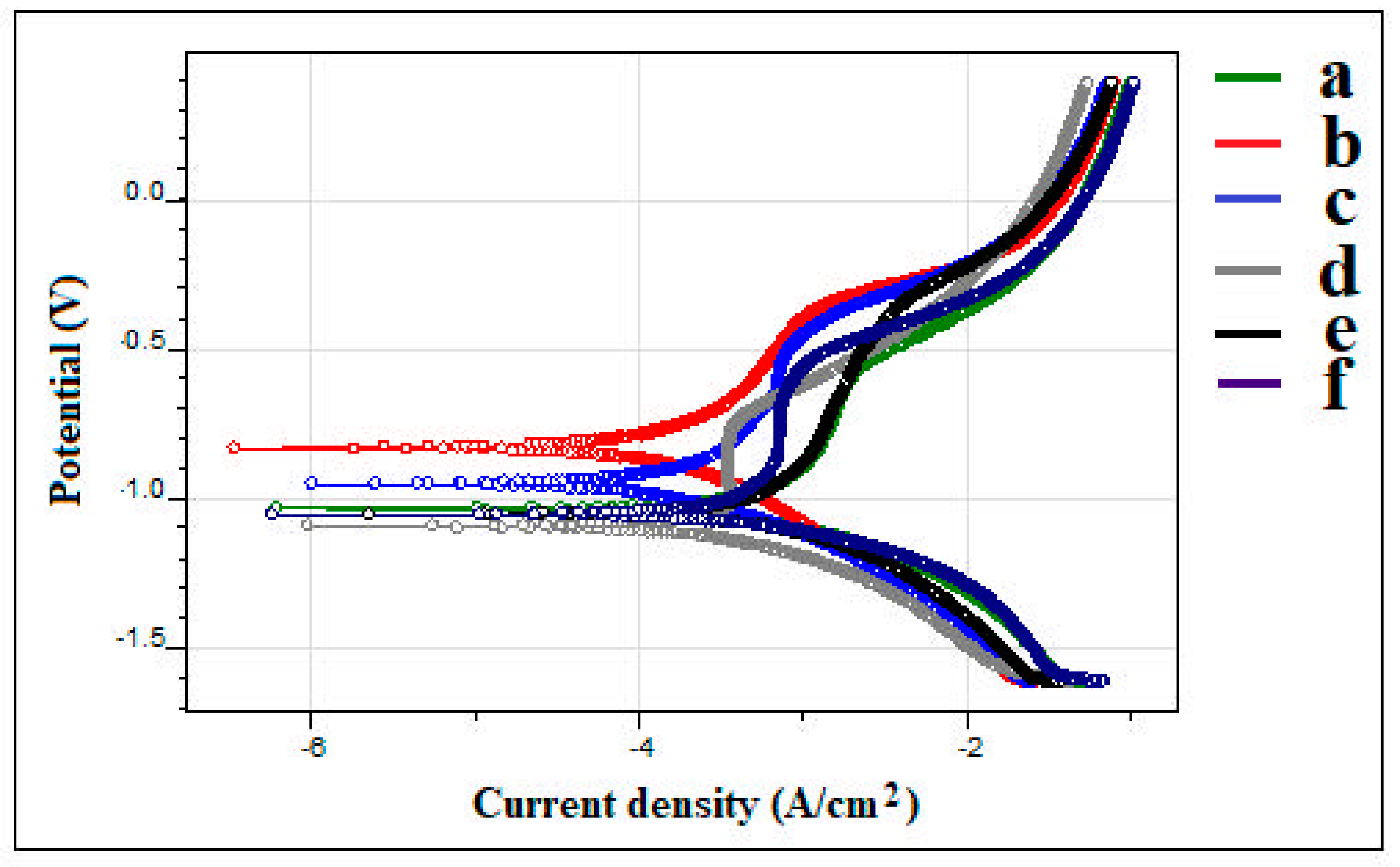
  • The Fe–2Cu compact has obtained a lower corrosion rate of 0.657 mmpy while related to the other sintered compacts.
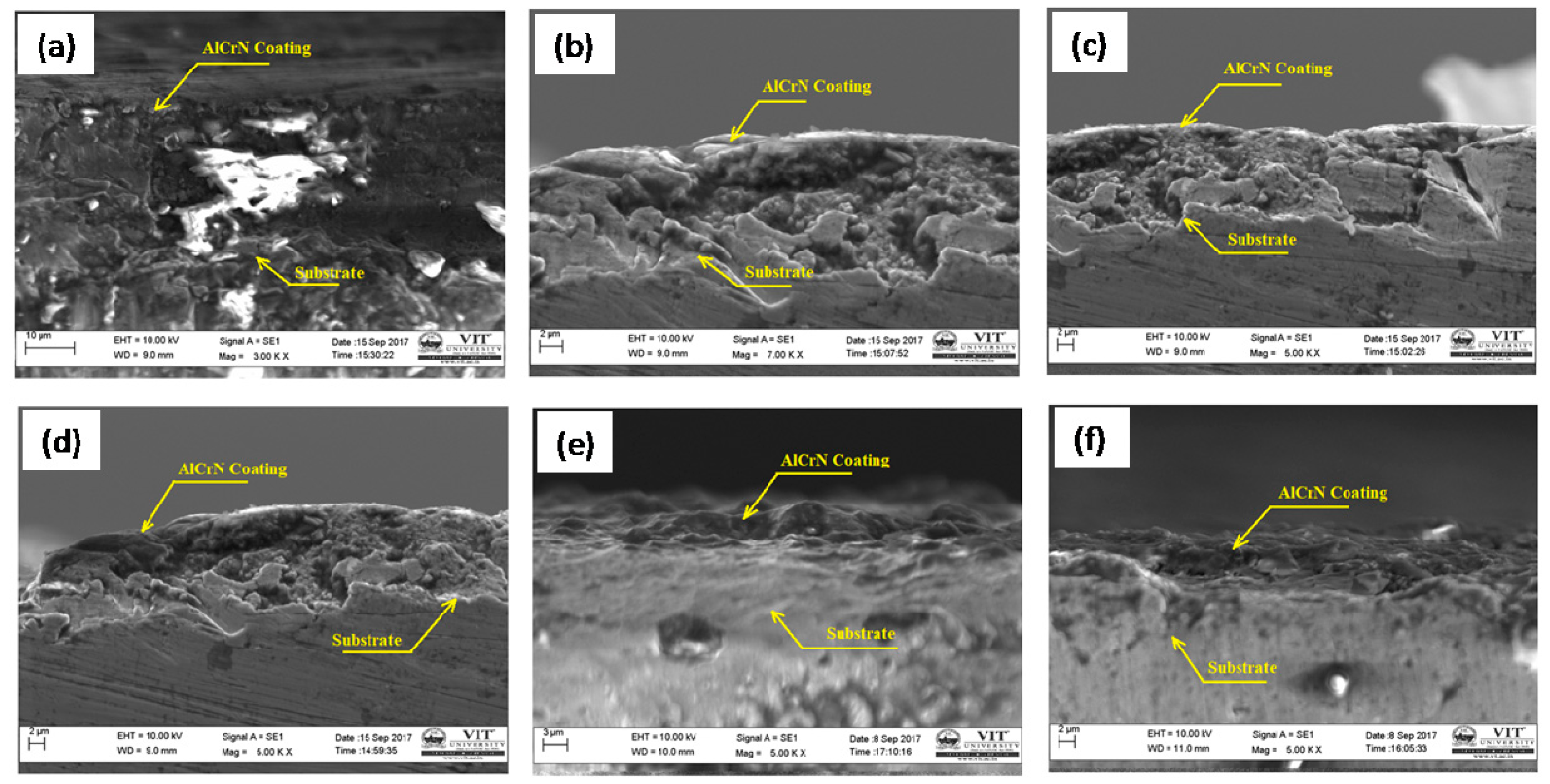
  • The SEM images clearly show that the interlayer diffusion of the AlCrN coating with the Fe–2Cu alloy sintered compacts.
  • The XRD analysis shows that the high peaks obtained for the AlN and CrN patterns and the average crystallite size from 38 to 58 nm was obtained.
  • The microhardness testing shows that the Fe–2Cu–0.8C–0.6Mo coated compact sample has obtained a high hardness of 1134.85 HV.
  • Fe–2Cu–0.8C–0.2Mo coated compact sample has obtained high corrosion resistance (0.08306 mmpy) compared to the other coated compact samples. Few pinholes and micro particles are formed on the coating surface of Fe–2Cu–0.8C–0.2Mo alloy compared with the other coated alloys.

Author Contributions

Conceptualization, T.S.K., A.R.A., and M.S.; methodology, T.S.K., A.R.A., and C.-P.J.; investigation, T.S.K., A.R.A., and C.-P.J.; resources, A.R.A. and C.-P.J.; data curation, M.S., A.R.A., and T.S.K.; writing—T.S.K., A.R.A., and C.-P.J.; writing—review and editing, T.S.K., A.R.A., M.S., and C.-P.J.; supervision, C.-P.J. All authors have read and agreed to the published version of the manuscript.

Funding

The authors would like to acknowledge the Ministry of Science and Technology of the Republic of China (Taiwan) under grants MOST 109-2221-E-194-011-MY2 and MOST 107-2221-E-194-024-MY3.

Acknowledgments

The authors T. Sampath Kumar and A. Raja Annamalai wish to express their thanks to Oerlikon Balzers Coating India, Ltd. Irrungattukottai, Chennai, India and VIT, Vellore campus for providing the facilities to perform these studies and to prepare the manuscript.

Conflicts of Interest

The authors declare no conflict of interest.

References

  1. Nekatibeb, F.; Annamalai, A.R.; Upadhyaya, A. Effect of copper and graphite addition on sinterability of iron. Trans. Indian Inst. Met. 2011, 64, 81–84. [Google Scholar] [CrossRef]
  2. Hadas, S.; Raja, A. Annamalai and Anish Upadhyaya, Effect of compaction pressure and tempering on densification, microstructural evolution, mechanical properties, wear, and machinability response of sinter hardened Ancorsteel 4300-0.6Gr. Mater. Technol. 2011, 26, 263–270. [Google Scholar] [CrossRef]
  3. Annamalai, A.R.; Upadhyaya, A.; Agarwal, D. Effect of heating mode on sintering of ferrous compacts through powder metallurgy route. Int. Heat Treat. Surf. Eng. 2011, 5, 155–160. [Google Scholar] [CrossRef]
  4. Upadhyaya, G.S. Sintered Metallic and Ceramic Materials Preparation, Properties and Applications; John Wiley & Sons Inc.: New York, NY, USA, 1999. [Google Scholar]
  5. Causton, R.J.; Davala, A.; Miller, T.J. Improved efficiency by use of sinter-hardened P/M automotive components. SAE Tech. Pap. 2000. [Google Scholar] [CrossRef] [Green Version]
  6. Annamalai, A.R.; Hadas, S.; Upadhyaya, A. Effect of compaction pressure on sinter hardening and tempered response on SH737-2CU-0.8C steels. Int. J. Mater. Sci. 2012, 7, 21–33. [Google Scholar]
  7. Annamalai, A.R.; Nekatibeb, F.; Upadhyaya, A.; Agarwal, D.K. Effect of heating mode on sinterability of carbonyl iron compacts. Mater. Res. Innov. 2013, 17, 10–16. [Google Scholar] [CrossRef]
  8. Annamalai, R.; Upadhyaya, A.; Agrawal, D. An investigation on microwave sintering of Fe, Fe–Cu, and Fe–Cu–C alloys. Bull. Mater. Sci. 2013, 36, 447–456. [Google Scholar] [CrossRef]
  9. Shon, Y.; Joshi, S.S.; Katakam, S.; ShankerRajamure, R.; Dahotre, N.B. Laser additive synthesis of high entropy alloy coating on aluminum: Corrosion behavior. Mater. Lett. 2015, 142, 122–125. [Google Scholar] [CrossRef]
  10. Li, Q.H.; Yue, T.M.; Guo, Z.N.; Lin, X. Microstructure and corrosion properties of AlCoCrFeNi high entropy alloy coatings deposited on AISI 1045 steel by the electro spark process. Met. Mater. Trans. 2012, 44, 1767–1778. [Google Scholar] [CrossRef]
  11. An, Z.; Jia, H.; Wu, Y.; Rack, P.D.; Patchen, A.D.; Liu, Y.; Ren, Y.; Li, N.; Liaw, P.K. Solid-solution CrCoCuFeNihigh-entropy alloy thin films synthesized by sputter deposition. Mater. Res. Lett. 2015, 3, 203–209. [Google Scholar] [CrossRef] [Green Version]
  12. Carboneras, M.; Hernández, L.S.; del Valle, J.A.; García-Alonso, M.C.; Escudero, M.L. Corrosion protection of different environmentally friendly coatings on powder metallurgy magnesium. J. Alloys Compd. 2010, 496, 442–448. [Google Scholar] [CrossRef] [Green Version]
  13. Pezzato, L.; Dabalà, M.; Gross, S.; Brunelli, K. Effect of microstructure and porosity of alsi10mg alloy produced by selective laser melting on the corrosion properties of plasma electrolytic oxidation coatings. Surf. Coat. Technol. 2020, 404, 126477. [Google Scholar] [CrossRef]
  14. Fernee, H.; Nairn, J.; Atrens, A. Precipitation hardening of Cu-Fe-Cr alloys. J. Mater. Sci. 2011, 36, 2711–2719. [Google Scholar] [CrossRef]
  15. Demetrio, K.; Klein, A.; Schaeffer, L.; Consoni, D.R.; Martinelli, A.E.; Bendo, T. Sinterability and microstructure evolution during sintering of ferrous powder mixtures. Mater. Res. 2013, 65, 1030–1038. [Google Scholar] [CrossRef] [Green Version]
  16. Baczek, E.; Konstantly, J.; Romanski, A.; Podsiadlo, M.; Cyboron, J. Processing and characterization of Fe–Mn–Cu–Sn–C alloys prepared by ball milling and spark plasma sintering. J. Mater. Eng. Perform. 2018, 27, 1475–1483. [Google Scholar] [CrossRef] [Green Version]
  17. German, R.M.; Suri, P.; Park, S.J. Liquid phase sintering. J. Mater. Sci. 2019, 44, 1–39. [Google Scholar] [CrossRef] [Green Version]
  18. Zhang, S.; Sun, D.; Fu, Y.Q.; Du, H.J. Recent advances of superhard nanocomposite coatings: A review. Surf. Coat. Technol. 2003, 167, 113. [Google Scholar] [CrossRef]
  19. ASTM E8/E8M-16ae1. Standard Test Methods for Tension Testing of Metallic Materials; ASTM International: West Conshohocken, PA, USA, 2016. [Google Scholar]
  20. Barshilia, H.C.; Deepthi, B.; Selvakumar, N.; Jain, A.; Rajam, K.S. Nanolayered multilayer coatings of CrN/CrAlN prepared by reactive DC magnetron sputtering. Appl. Surf. Sci. 2007, 253, 5076. [Google Scholar] [CrossRef]
  21. Muthuchamy, A.; Annamalai, A.R.; Karthikeyan, M.; Thakur, A.; Nagaraju, N.; Agrawal, D.K. Microstructural evolution of iron-based alloys produced by spark plasma sintering method. Phys. Met. Metallogr. 2018, 119, 678–684. [Google Scholar] [CrossRef]
  22. Tahir, A.M.; Amberg, G.; Hedström, P.; Bergman, O.; Frisk, K. Cu redistribution during sintering of Fe–2Cu and Fe–2Cu–0.5C compacts. Powder Metall. 2014, 57, 373–379. [Google Scholar] [CrossRef]
  23. ASTM G59-97. Standard Test Method for Conducting Potentiodynamic Polarization Resistance Measurements; American Society for Testing and Materials: West Conshohocken, PA, USA, 2014. [Google Scholar]
  24. Danninger, H. Sintering of Mo alloyed P/M steels prepared from elemental powders. Powder Met. Int. 1992, 24, 163–167. [Google Scholar]
  25. Chen, W.; Cheng, J.; Chen, P.; Zhang, J.; Wei, B. Preparation and performance of sintered Fe–2Cu–2Mo–0.8 C materials containing different forms of molybdenum powder. Materials 2019, 12, 417. [Google Scholar] [CrossRef] [PubMed] [Green Version]
  26. Raja Annamalai, A.; Upadhyaya, A.; Agrawal, D.K. Effect of heating mode and electrochemical response on austenitic and ferritic stainless steels. Can. Metall. Q. 2015, 54, 142–148. [Google Scholar] [CrossRef]
  27. Shi, Y.; Yang, B.; Liaw, P.K. Corrosion-resistant high-entropy alloys: A review. Metals 2017, 7, 43. [Google Scholar] [CrossRef] [Green Version]
  28. Braic, V.; Balaceanu, M.; Braic, M.; Vladescu, A.; Panseri, S.; Russo, A. Characterization of multi-principal-element (TiZrNbHfTa)N and (TiZrNbHfTa)C coatings for biomedical applications. J. Mech. Behav. Biomed. Mater. 2012, 1, 197–205. [Google Scholar] [CrossRef]
  29. Wan, X.S.; Zhao, S.S.; Yang, Y.; Gong, J.; Sun, C. Effects of nitrogen pressure and pulse bias voltage on the properties of Cr-N coatings deposited by arc ion plating. Surf. Coat. Technol. 2010, 204, 800–1810. [Google Scholar] [CrossRef]
  30. Musil, J.; Kunc, F.; Zeman, H.; Polakova, H. Relationships between Hardness, YoungÕs and elastic recovery in hard nanocomposite coatings. Surf. Coat. Technol. 2002, 154, 304–313. [Google Scholar] [CrossRef]
  31. Dobrzanski, L.A.; Zukowska, L.W. Properties of the multicomponent and gradient PVD coatings. Mater. Sci. Pol. Acad. Sci. 2017, 28, 621–624. [Google Scholar]
  32. Veprek, S.; Maritza, J.G.; Veprek–Hejiman, M. Industrial applications of superhard nanocomposite coatings. Surf. Coat. Technol. 2008, 202, 5063–5073. [Google Scholar] [CrossRef]
  33. Kumar, T.S.; Jebaraj, A.V. Metallurgical characterization of CrN and AlCrN physical vapor deposition coatings on aluminum alloy AA 6061. Mater. Today: Proc. 2020, 22, 1479–1488. [Google Scholar]
  34. Tański, T.; Dobrzańska-Danikiewicz, A.D.; Labisz, K.; Matysiak, W. Long-term development perspectives of selected groups of engineering materials used in the automotive industry. Arch. Met. Mater. 2014, 59, 1717–1728. [Google Scholar] [CrossRef] [Green Version]
  35. Żaba, K.; Nowosielski, M.; Kita, P.; Kwiatkowski, M.; Tokarski, T.; Puchlerska, S. Effect of heat treatment on the corrosion resistance of aluminized steel strips. Arch. Met. Mater. 2015, 60, 1825–1831. [Google Scholar] [CrossRef]
  36. Kumar, T.S.; Prabu, S.B.; Manivasagam, G. Metallurgical characteristics of TiAlN/AlCrN coating synthesized by the PVD process on a cutting insert. J. Mater. Eng. Perform. 2014, 23, 2877–2884. [Google Scholar] [CrossRef]
  37. Willmann, H.; Mayrhofer, P.H.; Hultman, L.; Mitterer, C. Thermal stability and age hardenings of supersaturated AlCrN hard coatings. Int. Heat Treat. Surf. Eng. 2017, 1, 75–79. [Google Scholar] [CrossRef]
  38. Feng, Y.; Zhang, L.; Ke, R.; Wan, Q.; Zhi, Z.; Lu, H. Thermal stability and oxidation behavior of AlTiN, AlCrN, and AlCrSiWN coatings. Int. J. Refract. Met. Hard Mater. 2014, 43, 241–249. [Google Scholar] [CrossRef]
  39. Kumar, T.S.; Prabu, S.B.; Madhavan, S.; Padmanabhan, K.A. Thermal stability of TiAlN/AlCrN and AlCrN/TiAlN coatings synthesized by the cathodic arc vapor deposition process on a tungsten carbide tool. Trans. Indian Inst. Met. 2018, 71, 665–676. [Google Scholar] [CrossRef]
  40. Chawla, V.; Chawla, A.; Mehta, Y.; Puri, D.; Prakash, S.; Sidhu, B.S. Investigation of properties and corrosion behavior of hard TiAlN and AlCrN PVD thin coatings in the 3 wt.% NaCl solution. J. Aust. Ceram. Soc. 2011, 47, 48–55. [Google Scholar]
Figure 1. Scanning electron microscope images of as-received powders (a) Carbonyl Fe, (b) Copper Powder, (c) Graphite powder, (d) Molybdenum powder.
Coatings 10 01166 g001
Figure 2. Representation outline sketch for the CAP-PVD system. (Source Diagram provided by OerlikonBalzers Limited, Balzers, Liechtenstein).
Coatings 10 01166 g002
Figure 3. Microstructures of the as-sintered (a) Fe, (b) Fe–2 Cu (c) Fe–2Cu–0.8C, (d) Fe–2Cu–0.8C–0.2Mo, (e) Fe–2Cu–0.8C–0.4Mo and (f) Fe–2Cu–0.8C–0.6Mo, compacts consolidated in a Spark Plasma furnace at 1120 °C for 5 min.
Coatings 10 01166 g003
Figure 4. SEM fractographs of (a) Fe, (b) Fe–2Cu, (c) Fe–2Cu–0.8C, (d) Fe–2Cu–0.8C–0.2Mo, (e) Fe–2Cu–0.8C–0.4Mo and (f) Fe–2Cu–0.8C–0.6Mo, compacts consolidated in a Spark plasma furnace at 1120 °C for 5 min [21], Red color arrow indicates brittle fracture, Blue color arrow indicates ductile fracture.
Coatings 10 01166 g004
Figure 5. Potentiodynamic polarization curves of carbonyl iron powder compacts sintered substrates. (a) Fe, (b) Fe–2Cu, (c) Fe–2Cu–0.8C, (d) Fe–2Cu–0.8C–0.2Mo, (e) Fe–2Cu–0.8C–0.4Mo, and (f) Fe–2Cu–0.8C–0.6Mo.
Coatings 10 01166 g005
Figure 6. SEM images of cross sectional area of the monolayer coating (a) Fe, (b) Fe–2Cu, (c) Fe–2Cu–0.8C, (d) Fe–2Cu–0.8C–0.2Mo, (e) Fe–2Cu–0.8C–0.4Mo and (f) Fe–2Cu–0.8C–0.6Mo.
Coatings 10 01166 g006
Figure 7. SEM micrographs of the coating (a) Fe, (b) Fe–2Cu, (c) Fe–2Cu–0.8C, (d) Fe–2Cu–0.8C–0.2Mo, (e) Fe–2Cu–0.8C–0.4Mo and (f) Fe–2Cu–0.8C–0.6Mo.
Coatings 10 01166 g007
Figure 8. XRD patterns for the AlCrN coated samples. (a) Fe, (b) Fe–2Cu, (c) Fe–2Cu–0.8C, (d) Fe–2Cu–0.8C–0.2Mo, (e) Fe–2Cu–0.8C–0.4Mo, and (f) Fe–2Cu–0.8C–0.6Mo.
Coatings 10 01166 g008
Figure 9. Potentiodynamic polarization curves of AlCrN monolayer coated samples. (a) Fe, (b) Fe–2Cu, (c) Fe–2Cu–0.8C, (d) Fe–2Cu–0.8C–0.2Mo, (e) Fe–2Cu–0.8C–0.4Mo, and (f) Fe–2Cu–0.8C–0.6Mo.
Coatings 10 01166 g009
Table 1. As-Received Powder Specification.
CharacteristicsFeCuGraphiteMo
Apparent density, (g/cm3)3.102.030.172.59
Tap density, (g/cm3)3.503.280.332.5
Flow rate, (s/50 g)29.29Non flowingNon flowingNon flowing
Particle size, (μm)D1032.684.173.906.80
D5090.129.58.8423.56
D90179.8020.1617.7758.08
Theoretical density, (g/cm3)7.866.922.3210.2
Surface area (m2/g)0.6680.2460.8420.576
Table 2. CAP-PVD process parameters for AlCrN monolayer coating.
Process FactorsStandards with Units
AlCrN monolayer coating thickness5 ± 1 µm
Substrate temperature400 ± 10 °C
Power supply for targets5 kW
Coating period160 min
Nitrogen rate of flow1250 sccm
Compartment pressure3.4 × 10−2 mbar
Voltage/current30 Volts/160 amps
Feed rate60 mg/min for each target
Distance between target and substrate200 mm
Table 3. Effect of varying alloying addition on the densification response of carbonyl iron powder compacts sintered in Spark plasma heating furnace [21].
CompositionSintered Density % (ρs)
Fe90.18 ± 1.21
Fe–2Cu93.85 ± 2.60
Fe–2Cu–0.8C94.29 ± 1.96
Fe–2Cu–0.8C–0.2Mo95.63 ± 2.254
Fe–2Cu–0.8C–0.4Mo96.83 ± 2.14
Fe–2Cu–0.8C–0.6Mo97.20 ± 2.89
Table 4. Rockwell hardness values of Fe and its alloying additions consolidated in Spark plasma sintering furnace.
CompositionHardness (HRB)
Spark Plasma Sintered Compacts
Fe45 ± 3.43
Fe–2Cu47 ± 2.1
Fe–2Cu–0.8C79 ± 5.21
Fe–2Cu–0.8C–0.2Mo88 ± 2.6
Fe–2Cu–0.8C–0.4Mo95 ± 1.59
Fe–2Cu–0.8C–0.6Mo96 ± 3.2
Table 5. Effect of alloying addition on the tensile properties of carbonyl iron compacts [21].
SampleUTS (MPa)Yield Strength (MPa)Elongation %Reduction in Area %
Fe444 ± 12266 ± 56.31.3
Fe–2Cu497 ± 8298 ± 79.40.8
Fe–2Cu–0.8C772 ± 6463 ± 45.30.4
Fe–2Cu–0.8C–0.2Mo900 ± 6546 ± 75.10.6
Fe–2Cu–0.8C–0.4Mo918 ± 3553 ± 44.90.4
Fe–2Cu–0.8C–0.6Mo1000 ± 5600 ± 43.20.6
Table 6. Potentiodynamic polarization values attained from the electrochemical experiment for carbonyl iron powder compacts sintered substrates.
SamplesEcorr
(V)
icorr
(A/cm2)
Rp
(Ohms)
CR
(mmpy)
Fe−1.05850.00082594.272.7
Fe–2Cu−0.83870.0002011482.40.6579
Fe–2Cu–0.8C−0.95930.00022663390.7415
Fe–2Cu–0.8C–0.2Mo−1.09810.0003012252.30.9856
Fe–2Cu–0.8C–0.4Mo−1.06030.0005948124.11.946
Fe–2Cu–0.8C–0.6Mo−1.07130.0004539104.61.485
Table 7. Elemental composition analysis on the coated samples.
SubstrateCoatingElements
Nitrogen (N)Aluminum (Al)Chromium (Cr)
AlCrNWeight% (100)Atomic% (100)Weight% (100)Atomic% (100)Weight% (100)Atomic% (100)
Fe29.3452.3630.728.4439.9519.20
Fe–2Cu28.4051.0331.8729.7339.7319.23
Fe–2Cu–0.8C30.6053.7130.7428.0138.6618.28
Fe–2Cu–0.8C–0.2Mo30.3453.7129.5927.1940.0719.11
Fe–2Cu–0.8C–0.4Mo27.7350.1330.0028.6742.7721.21
Fe–2Cu–0.8C–0.6Mo27.5350.0631.8030.0240.6719.92
Table 8. Hardness values for the AlCrN coated substrates.
CoatingSubstrateHardness (HV)
AlCrNFe171.55 ± 5.6
Fe–2Cu191.10 ± 6.1
Fe–2Cu–0.8C336.65 ± 5.65
Fe–2Cu–0.8C–0.2Mo452.40 ± 8.93
Fe–2Cu–0.8C–0.4Mo517.30 ± 9.63
Fe–2Cu–0.8C–0.6Mo1134.85 ± 11.3
Table 9. Potentiodynamic polarization data attained from the corrosion test.
CoatingSamplesEcorr (V)icorr (A/cm2)Rp (Ohms)CR (mmpy)
AlCrNFe−0.48580.0000599215930.196
Fe–2Cu−0.33940.0000360277850.1179
Fe–2Cu–0.8C−0.27120.0000331722580.1085
Fe–2Cu–0.8C–0.2Mo−0.36490.0000253921770.08306
Fe–2Cu–0.8C–0.4Mo−0.29520.0000315518980.1032
Fe–2Cu–0.8C–0.6Mo−0.68960.00008557526.20.280
Publisher’s Note: MDPI stays neutral with regard to jurisdictional claims in published maps and institutional affiliations.

