Article

An In-Situ Electroplating Fabricated Fabry-Perot Interferometric Sensor and Its Temperature Sensing Characteristics

1
Key Lab for Robot & Welding Automation of Jiangxi Province, Mechanical and Electrical Engineering School, Nanchang University, Nanchang 330031, China
2
The Engineering Training Center of Nanchang University, Nanchang University, Nanchang 330031, China
3
Jiangnan Shipyard (Group) Co., Ltd., Shanghai 201913, China
*
Authors to whom correspondence should be addressed.
Coatings 2020, 10(12), 1174; https://doi.org/10.3390/coatings10121174
Submission received: 11 November 2020 / Revised: 25 November 2020 / Accepted: 27 November 2020 / Published: 30 November 2020

Abstract

:
In this study, in-situ electroplating method was used to fabricate a metal joint fixed extrinsic Fabry-Perot interferometric (EFPI) sensor. Specifically, optical fibers were firstly chemical plated with a very thin conductive nickel layer and then electroplated with nickel coating. After that, in-situ electroplating method was used to fix the metallized optical fibers and the capillary steel tube, the reflection spectra changes of the EFPI sensors during the in-situ electroplating process were recorded in real time, and the temperature sensing characteristics of the EFPI sensors were studied assisted by the temperature sensing system. Results show that: (i) optical fibers are well protected by the nickel layer; (ii) the reflection spectra of the EFPI sensors are clear and complete in the whole in-situ electroplating process, it is feasible to fabricate a EFPI sensor with the in-situ electroplating method; (iii) with the increases of temperature, the peak numbers of the reflection spectra of the EFPI sensors increase gradually; (iv) the EFPI sensors with different cavity length based on the in-situ electroplating method show excellent sensing characteristics, the temperature sensitivities reach up to about 700, 600, and 400 pm/°C from room temperature to 400 °C, respectively.

1. Introduction

Optical fiber sensor as a new type of sensor has been developed rapidly in recent years. Compared with traditional sensors based on electricity, optical fiber sensor has a series of advantages, such as light weight, high sensitivity, good resistance to electromagnetic interference, excellent electrical insulation and safety performance [1]. So far, optical fiber sensor has been widely used to monitor strain [2,3], temperature [4,5,6], refractive index [7], humidity [8], acceleration [9], ultrasound [10,11], displacement [12] and other physical quantities. According to whether occur light interferes or not, optical fiber sensors can be divided into interferometric optical fiber sensors and non-interferometric optical fiber sensors, of which interferometric optical fiber sensors normally have higher accuracy [13,14,15]. Interferometric optical fiber sensors can be divided into several types according to their internal structures, including Michlson sensor [16], Mach-Zehnder sensor [17], Sagnac sensor [18], Fabry-Perot sensor and so on. Due to a series of advantages, such as simple structure, miniature size, high reliability, ease of fabrication and the ability of transmitting signal in a single optical fiber, Fabry-Perot (F-P) sensor has a wide range of applications in many fields [19,20,21,22].
According to the structure type of the sensor head, F-P sensors can be divided into intrinsic Fabry-Perot interferometric (IFPI) sensors, extrinsic Fabry-Perot interferometric (EFPI) sensors, and in-line Fabry-Perot interferometric sensors. Among them, the light reflection occurs inside the IFPI sensor [23]. Different from the IFPI sensor, there is a cavity in the EFPI sensors, the cavity length will change along with the changes of the measured parameters. By calculating the change of the cavity length, it is possible to sense the changes of the external measured parameters [24]. In-line Fabry-Perot interferometric sensors have a composite structure of intrinsic and extrinsic type, thus having some characteristics of the above two type F-P sensors. Because of the difficulties of the fabrication process of the In-line Fabry-Perot interferometric sensor, the studies of in-line Fabry-Perot interferometric sensor are not as extensive as IFPI sensor and EFPI sensor. Among the above three types of optical fiber F-P sensors, the EFPI sensor has the advantages of easy fabrication, small size, low cost production, wide wavelength adjustment range, high precision and so on. Therefore, it has been received extensive attentions [25,26].
There are many kinds of EFPI sensors, the most typical structure is collimating the incident and reflective optical fibers in a capillary tube, the size of the capillary tube matches the external diameter of the optical fiber to ensure that their axis are aligned on a straight line. A device can be used to adjust or manually change the position of the optical fibers in the capillary tube finely to ensure the positions of the optical fibers and tube. After the position is determined, fix the optical fibers and the capillary tube with a specific method. In the previous work, three kinds of methods have been used to fix the optical fibers and the capillary tubes in the fabrication process of the EFPI sensor: arc welding; organic glue bonding; laser hot-melting. As early as 1988, Taylor et al. [27] used the arc welding method to fabricate an optical fiber sensor firstly. The arc welding method was then used to fabricate optical fiber EFPI sensors in the subsequent studies [28,29]. In the work of Jiang [30] and Li et al. [31], different organic glues were used to fabricate optical fiber EFPI sensors. Liu et al. [32] fixed the optical fibers and the silica glass capillary channel by the CO2 laser hot-melting method. They pointed out that the CO2 laser hot-melting fixed optical fiber EFPI sensors can be used in much higher temperature than that of the glue bonded sensors. Although the methods mentioned above may be effective, but have their own disadvantages. The arc welding and the laser hot-melting have some similar disadvantages, the fabrication equipment is expensive, fabrication processes are complicated, optical fibers and capillary tubes can be easily damaged during the high temperature heating processes. The method of fixing with organic glue is not reliable and limited by the characteristics of glue, which may not work in harsh environments of high pressure and high temperature.
In order to solve the problems mentioned above, the in-situ electroplating method was used to fabricate EFPI sensors in this study. The specific method was to insert the incident and reflective optical fibers into a capillary steel tube from the ends of the tube, respectively. Changed the position of the optical fibers to form an F-P cavity, when the EFPI sensor generated stable reflection spectrum, the optical fibers and capillary steel tube were fixed by the in-situ electroplating method. The structure of the EFPI sensor is simple and stable, the fabrication method is reliable. The reflection spectral changes during the electroplating process and its temperature sensing characteristics were then studied.

2. Experiment

2.1. EFPI Sensor Structure

The specific steps include chemical plating, electroplating and in-situ electroplating of the optical fibers and the capillary steel tube. The EFPI sensor is consisted of incident optical fiber, reflective optical fiber and a capillary steel tube, the structure is presented in Figure 1.

2.2. Preparation of EFPI Sensor

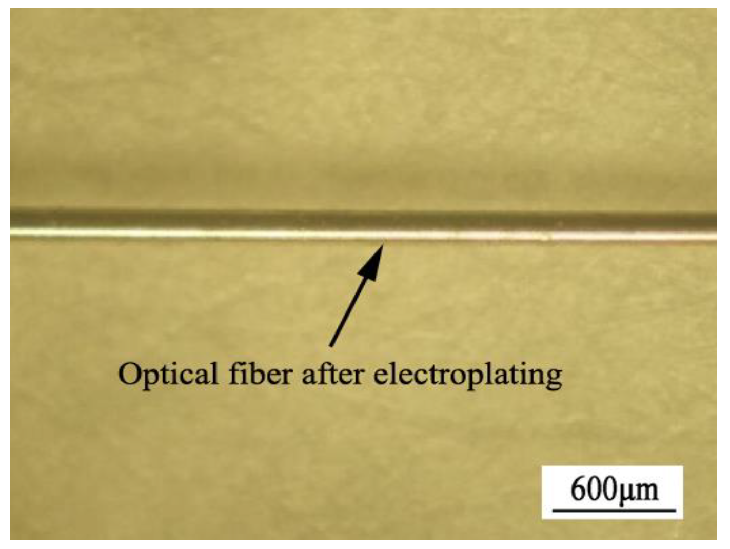
The preparation process includes chemical stripping of the acrylate layer, surface metallization of the incident and reflective optical fibers, chemical stripping and slicing of the ends of the metalized optical fibers. Optical fiber used in this study is acrylate coated Corning SMF-28 standard single-mode optical fiber (Corning, NY, USA), the diameter of the bare optical fiber is 125 μm. In order to increase the external diameter of the optical fibers and protect them, optical fibers were firstly coated with a very thin conductive nickel layer by chemical plating (the blue layer in Figure 1) and then electroplated with a thicker nickel coating (the yellow layer in Figure 1), until the external diameter was increased to about 185–195 μm. Note, the optical fibers were only partially metalized, the coated length of the incident and reflective optical fibers were about 10 cm with the thickness of 30–35 μm. The process of chemical plating is as follows: (i) remove the organic protective layer; (ii) remove the oil impurities and dust; (iii) sensitization; (iv) activation; (v) chemical plating. The specific chemical plating and electroplating processes have been elaborated in our previous studies [33]. The outview of the chemical plated optical fiber and the electroplated optical fiber is shown in Figure 2 and Figure 3. After electroplating, the ends of two optical fibers were put into the concentrated nitric acid solution for chemical removing of nickel coating of 2 cm length. Then, cleaned the bare optical fiber surface by alcohol and deionized water, and sliced the two ends of the incident and reflective optical fiber.

2.3. In-Situ Electroplating

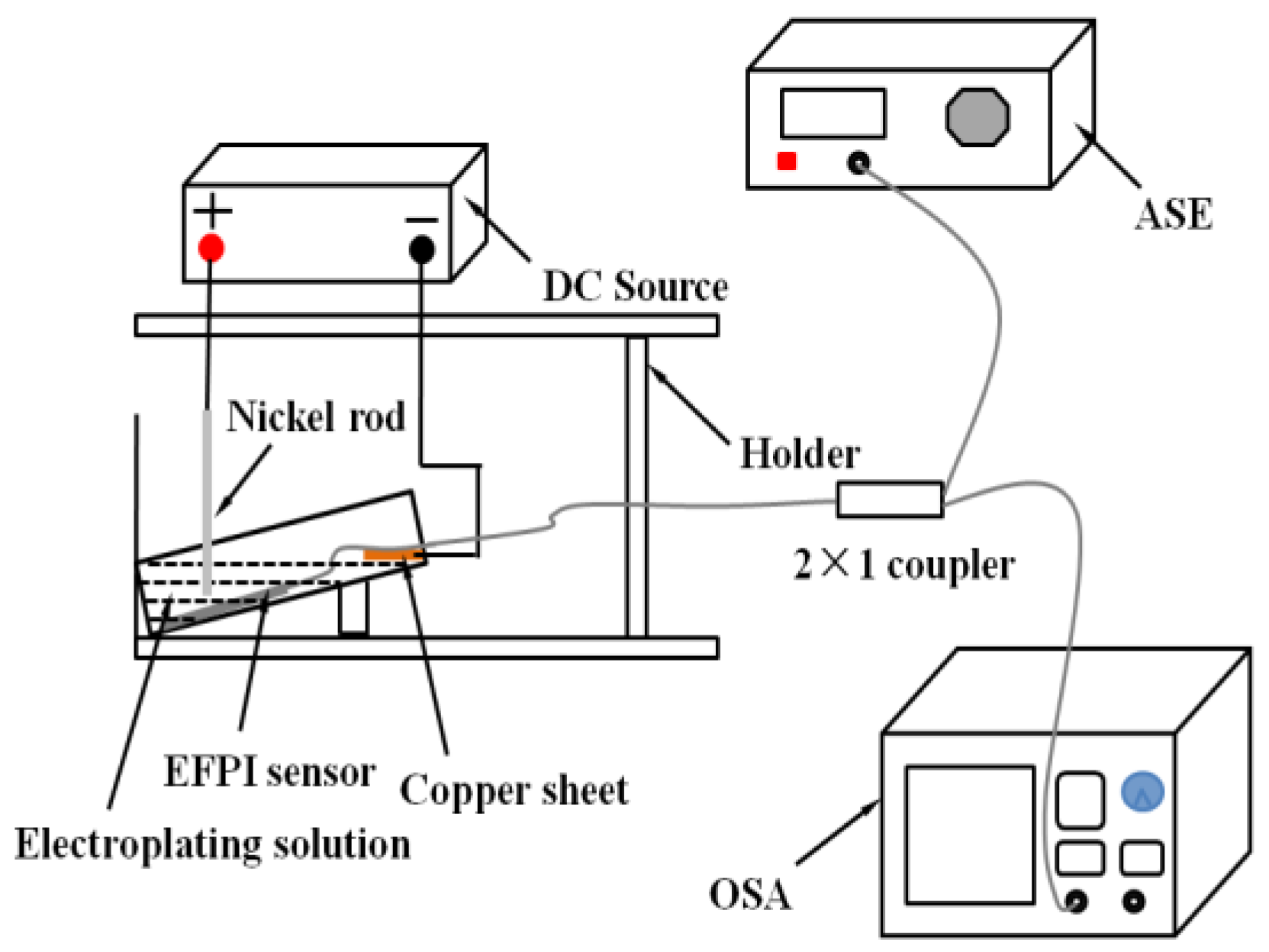
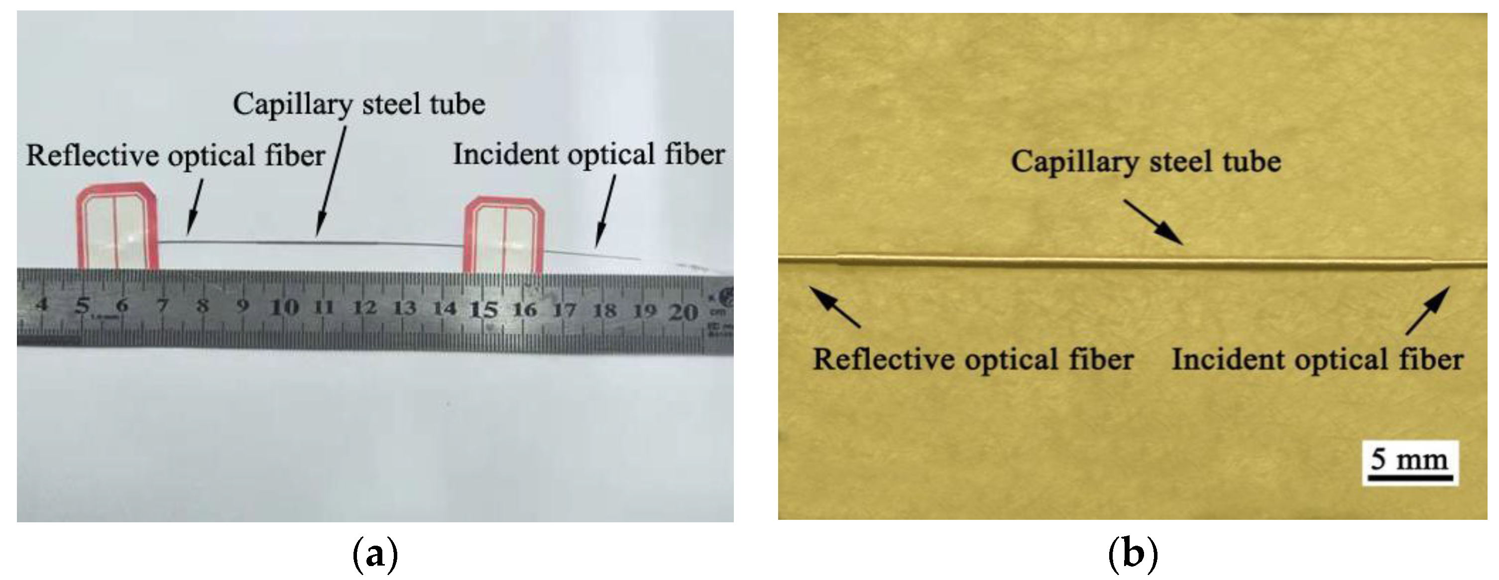
The in-situ electroplating method was used to fix the optical fibers and a capillary steel tube in this study. Before electroplating, one optical fiber was cut to about 5 cm as the reflective optical fiber, the other was set as the incident optical fiber(as seen in Figure 1). The incident optical fiber was connected to the OSA (Optical Spectrum Analyzer, AQ6370D, YOKOGAWA, Tokyo, Japan), and then the cut-flat ends of the incident and reflective optical fibers were inserted into the capillary steel tube with the internal diameter of 200 μm to form an F-P cavity. Change the position of the optical fibers when the EFPI sensor generated stable reflection spectrum, put it in the electroplating solution, and conduct the plating. During the plating, the EFPI sensor was connected to the negative electrode of the source of direct current through a copper sheet, a high-purity nickel rod was connected to the positive electrode. The current was set as about 5 mA and the electroplating time were about 8 h to ensure the fixing of the optical fibers and the capillary steel tube the electroplating nickel layer was shown as the red layer in Figure 1. The OSA was used to record the reflection spectra changes of the EFPI sensor during the electroplating process. The schematic diagram of the EFPI sensor electroplating setup based on the in-situ electroplating method is presented in Figure 4. Figure 5 exhibits the outview of an EFPI sensor. As shown in Figure 5, the surface of the EFPI sensor is smooth, compact and bright.

2.4. Temperature Sensing Experiment

Temperature sensing experiment was carried out with the sensing system of an ASE light source (Amplified Spontaneous Emission, Beijing Photonbyte Technology Co., Ltd., Beijing, China), a fiber circulator, an EFPI sensor, an OSA, a KSY silicon-controlled temperature controller (Yuyao Jindian Instrument Co., Ltd., Yuyao, China) and a thermocouple (SBWR-230/238A, Shanghai Automation Instrument Three Factory, Shanghai, China), as shown in Figure 6.
The spontaneous emission light of the ASE source was used as the input light, which was input from port 1 of the fiber circulator and output from port 3 to the EFPI sensor. The incident light traveled along the core of the incident fiber was reflected by the two surfaces of the cavity of the EFPI sensor and recombined in the core of the incident fiber. The two reflected lights of the EFPI sensor resulted in an interference spectrum, which was transmitted to the OSA from port 2. The resolution of the OSA is 0.02 nm, which was used to record the reflection spectra changes of the EFPI sensor during the temperature sensing process. The KSY silicon-controlled temperature controller with a temperature resolution of 1 °C was used to provide a temperature controlled environment. The reflection spectra changes of the EFPI sensor during temperature sensing process was recorded and analyzed. During temperature sensing process, the EFPI sensor was heated from 22 (room temperature) to 400 °C with a rate of 10 °C/min, and then cooled down to room temperature, the reflection spectrum was recorded every temperature rise of 100 °C. At the temperature sensing process, the display temperature of the thermocouple was used as a reference. Temperature sensing process was repeated at least three times of each EFPI sensor to confirm the repeatability (named test-1, test-2 and test-3).

3. Results and Discussions

The results are presented in those stages: spectral characteristics of EFPI sensors during the in-situ electroplating process, spectral characteristics of the EFPI sensors during the temperature sensing process, temperature sensitivities of EFPI sensors.

3.1. Spectral Characteristics of EFPI Sensors during the In-Situ Electroplating Process

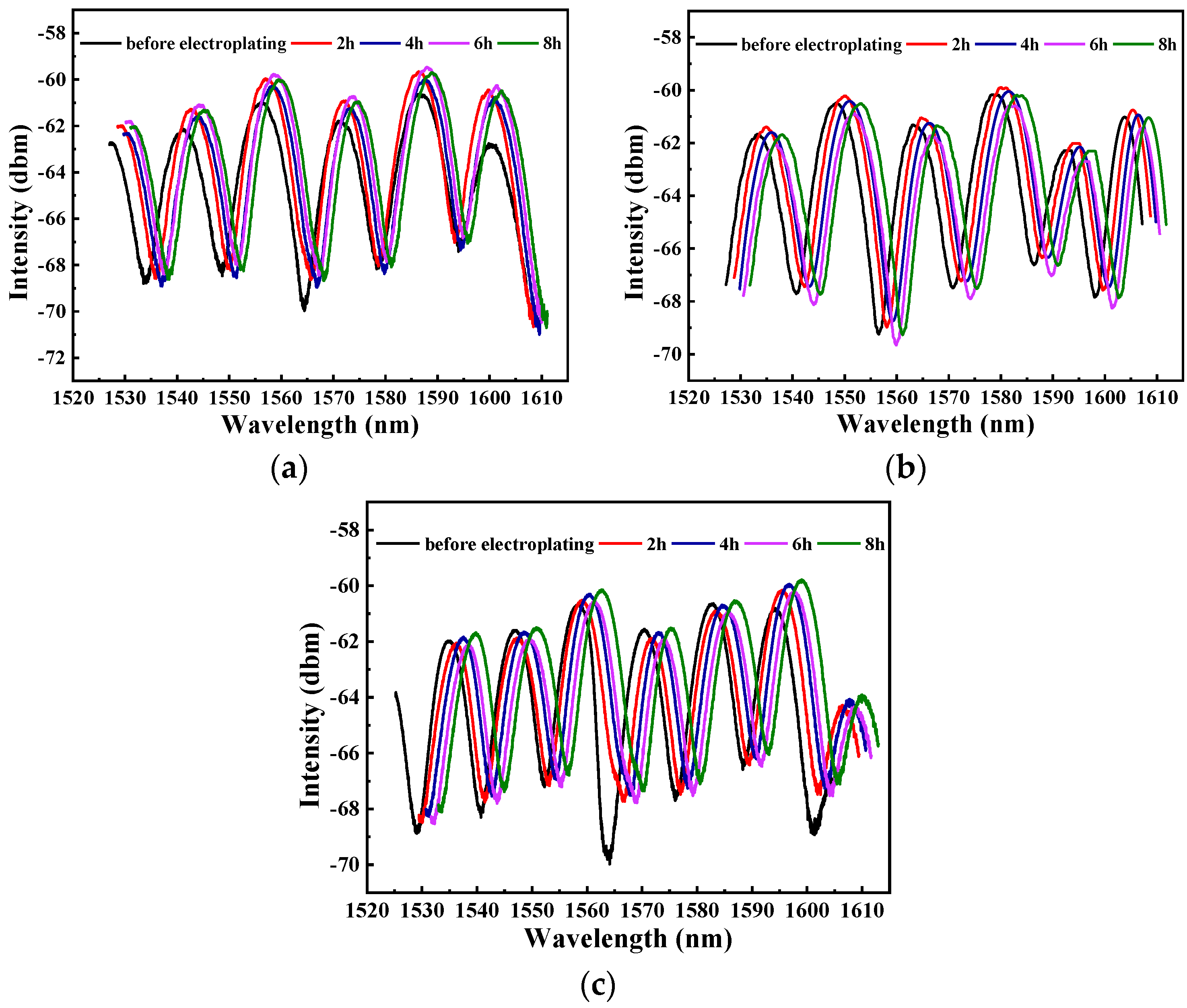
The reflection spectrum of the EFPI sensor is formed by the interference between the reflected lights at the incident and reflective interfaces of the EFPI sensor. In order to analyze and control the process, the reflection spectra changes of the EFPI sensors were recorded during the real time in-situ electroplating process. Three EFPI sensors with different cavity lengths were fabricated by the in-situ electroplating method (named EFPI-1, EFPI-2 and EFPI-3). Figure 7a–c show the reflection spectra changes of EFPI-1, EFPI-2 and EFPI-3 during the in-situ electroplating process, respectively. As shown in Figure 7, the reflection spectra are clear and complete during the whole electroplating process. The reflection spectra of EFPI-1, EFPI-2 and EFPI-3 shift toward higher wavelength with the increase of electroplating time, this phenomenon maybe caused by the compressive stress applied on the EFPI sensor, which is produced in the electroplating process [34]. From Figure 7, it can be known that the EFPI sensor was not damaged during the in-situ electroplating process. So, it is feasible to fabricate an EFPI sensor with the in-situ electroplating method.
Figure 8 shows the reflection spectra of the EFPI sensors after in-situ electroplating at room temperature, it can be seen that the reflection spectra are complete and continuous, temperature sensing experiments can be carried out on the EFPI sensors.

3.2. Spectral Characteristics of the EFPI Sensors during the Temperature Sensing Process

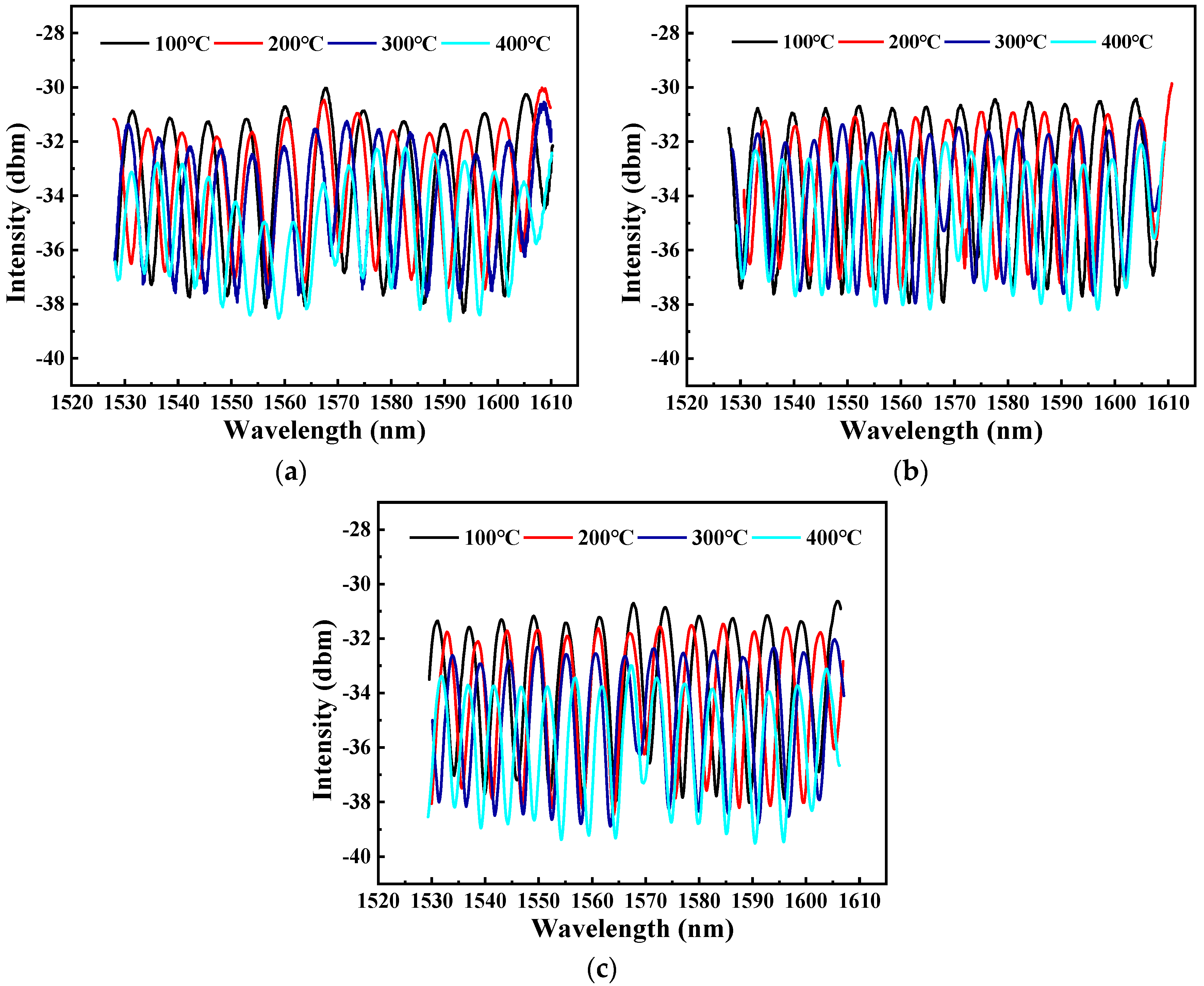
In the previous studies [35,36,37], the optical fiber F-P sensor has been used to detect various physical quantities, such as temperature, strain and pressure. The EFPI sensor fabricated in this study is based on silica and plated metal joint structure, which may be used in a higher temperature environment. In order to study the temperature sensing characteristics of the EFPI sensor based on the in-situ electroplating method, sensing experiments were carried out, the reflection spectra of the EFPI sensors in the dynamic heating process are presented in Figure 9.
It can be seen from Figure 9 that the peak numbers of all reflection spectra of EFPI-1, EFPI-2 and EFPI-3 increase gradually with the increase of temperature. At the temperature of 100 °C, the reflection spectrum of EFPI-1 has 11 peaks, when the temperature was increased to 400 °C, the peak number increased to 15. The reflection spectra of EFPI-2 and EFPI-3 show the similar changes. According to the sensing principle of the optical fiber F-P sensor, the equation of the cavity length of the optical fiber F-P sensor and the two adjacent peaks in the reflection spectrum can be expressed as [38,39]:
L =   λ 1 λ 2 2 ( λ 1 λ 2 )
where L is the cavity length of the optical fiber F-P sensor, λ1 and λ2 represent the wavelengths of two adjacent peak points in the reflection spectrum.
We sequentially substituted the wavelengths of two adjacent peak points in the reflection spectra of EFPI-1, EFPI-2 and EFPI-3 in different temperatures into Equation (1), obtained the cavity length of EFPI-1, EFPI-2 and EFPI-3 at different temperatures, which are shown in Table 1, Table 2 and Table 3. As presented in the tables, with the increase of temperature, the cavity lengths of the EFPI sensors increase gradually, which is in accord with the expectations.
In addition, it is worth noting that the peak intensities of the reflection spectra decrease gradually with the increase of temperature, this phenomenon is similar to the previous studies [40]. The decreases of the peak intensities are considered to be related to the loss of the light, because that the thermal expansion coefficient of the capillary steel tube is much higher than that the optical fiber. With the increase of temperature, the swell increment of the capillary steel tube will be longer than that of the optical fiber, which will generate axial stress to the optical fiber. The optical fiber bends under this axial stress, so the loss of the light increases with the increase of temperature [40].

3.3. Temperature Sensitivities of EFPI Sensors

Temperature sensitivity is one of the important parameters of EFPI sensor. In order to study the temperature sensing characteristics of the EFPI sensor based on the in-situ electroplating method, temperature sensing experiment was carried out with the sensing system. Temperature sensing processes (include heating process and cooling process) were repeated at least three times of each EFPI sensor to confirm the reliability and the repeatability.
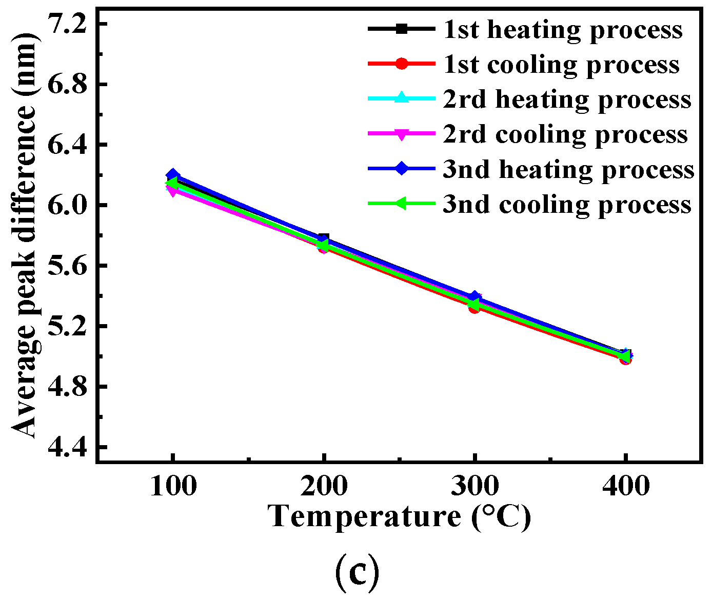
It can be known from Figure 9 that the peak numbers of all reflection spectra of EFPI-1, EFPI-2 and EFPI-3 increase gradually with the increases of temperature. The average peak differences (two adjacent peaks) of the reflection spectra of EFPI-1, EFPI-2 and EFPI-3 in different temperatures were calculated in this study, and obtained the curves of average peak difference and temperature of EFPI-1, EFPI-2 and EFPI-3, which are presented in Figure 10. The linearity of the curves of the average peak difference and temperature of EFPI-1, EFPI-2 and EFPI-3 is presented in Table 4. As illustrated in Table 4 and Figure 10, the curves of the average peak difference and temperature of EFPI-1, EFPI-2 and EFPI-3 are all liner in both heating and cooling processes, the linearity of all the curves of the average peak difference and temperature is above 99.7%, the repeatability errors of the three measurement cycles of EFPI-1, EFPI-2 and EFPI-3 are 3.67%, 3.58% and 3.36%, which indicates the EFPI sensors have good repeatability, the temperature sensitivities of EFPI-1, EFPI-2 and EFPI-3 reach up to about 700, 600, and 400 pm/°C in the whole temperature range, the achievable resolutions of EFPI-1, EFPI-2 and EFPI-3 are about 0.0014, 0.0016, and 0.0025 °C, respectively. It is noted that the temperature sensitivity of EFPI-1 is higher than EFPI-2 and EFPI-3, because that the cavity length of EFPI-1 is shorter than that of EFPI-2 and EFPI-3. It can be seen from Figure 10 that the curves at the edges of the range for several cycles are divergent. This phenomenon maybe related to the hysteresis responses of the EFPI sensors. At the edges of the curves, the change of temperature is sharply, the EFPI sensors can not response in time, which results in the error of the average peak differences at the edges of the curves.
The temperature sensitivity of optical fiber F-P sensor can be described as:
λ T   =   λ L · L T   =   λ L · L T
where λ can be the wavelength of any peak of the reflection spectrum of optical fiber F-P sensor, L is the cavity length of the optical fiber F-P sensor at a certain temperature.
The cavity length of the EFPI sensor will increase with the increase of temperature, the equation of the cavity length and temperature is:
L T   =   α · d
where α is the thermal expansion coefficient of the optical fiber F-P sensor, d is the initial length of the optical fiber F-P sensor. Substituting Equation (3) to Equation (2) obtains the following equation:
λ T = λ L · α · d
From Equation (4), it can be seen that when the increase of temperature is constant, to any peak of the reflection spectrum of the EFPI sensor, the EFPI sensor with shorter cavity length has greater wavelength shift. Therefore, the temperature sensitivity of EFPI-1 is higher than that of EFPI-2 and EFPI-3. In summary, the EFPI sensor based on the in-situ electroplating method show excellent sensing characteristics during the temperature sensing process.
The ceiling temperature in this study is 400 °C, this can be discussed. The metal plating joint may be applied in a much higher temperature, however, during the test, the application temperature was limited by the linear thermal expansion coefficient of the nickel layer and the light loss of the EFPI sensor. In the work of Zinov’Ev [41] and Abdullaev [42], the relationship between the linear thermal expansion coefficient of nickel and temperature were studied, they all discovered that when the temperature reached the Curie temperature point (about 400 °C), the linear thermal expansion coefficient changed sharply, which induced a nonlinear relationship between the average peak difference and temperature. Besides, as illustrated in Figure 10, the light loss of the EFPI sensor increases with the increase of temperature. When the temperature exceeds 400 °C, the light loss of the EFPI sensor increased sharply. In summary, when the temperature exceeds 400 °C, the EFPI sensor can not be used for temperature sensing, so the ceiling temperature in this study is 400 °C.

4. Conclusions

Optical fibers were firstly coated with a thin conductive nickel layer by chemical plating and then electroplated with nickel. The in-situ electroplating method was used to fix the metallized optical fibers and the capillary steel tube, the spectral changes of the EFPI sensors during the in-situ electroplating process were recorded in real time. The feasibility to fabricate EFPI sensor with the in-situ electroplating method was verified.
The temperature sensing characteristics of the EFPI sensors were studied assisted by a temperature sensing system. Results show that, with the increase of temperature, the peak numbers of the reflection spectra of the EFPI sensors increase gradually. The EFPI sensors with different cavity lengths based on the in-situ electroplating method show excellent sensing characteristics, the temperature sensitivities reach up to about 700, 600, and 400 pm/°C in the range from room temperature to 400 °C, respectively.

Author Contributions

Conceptualization, Y.L. and H.O.; methodology, S.L., Y.L., and H.O.; software, S.L. and T.D.; validation, Y.L. and T.D.; formal analysis, S.L. and X.L. (Xubo Liu); investigation, S.L.; resources, Y.L. and H.O.; data curation, X.L. (Xuewen Li), T.D., and X.L. (Xubo Liu); writing—original draft preparation, S.L.; writing—review and editing, Y.L.; visualization, S.L. and T.D.; supervision, X.L. (Xuewen Li) and T.D.; project administration, Y.L. and H.O.; funding acquisition, Y.L. All authors have read and agreed to the published version of the manuscript.

Funding

This work was sponsored by the Academic and Technical Leaders Founding Project of Major Disciplines of Jiangxi Province (20182BCB22001), the Science and Technology Innovation High Level Talent Project of Double Thousand Plan of Jiangxi Province (Certificate number: jxsq2019201048).

Conflicts of Interest

The authors declare no conflict of interest.

Nomenclatures

Fabry-Perot interferometric sensor: A sensor based on the principle of multi-beam interference to detect the changes of measurement. Intrinsic Fabry-Perot interferometric (IFPI) sensor: A Fabry-Perot sensor with modulation region inside optical fiber, optical fiber plays the role of light transmission and sensing the change of external signal at the same time. Extrinsic Fabry-Perot interferometric (EFPI) sensor: A Fabry-Perot sensor with an air cavity or other non-optical media inside, which can monitor the change of measurement by measuring the change of its cavity length. In-line Fabry-Perot interferometric sensor: A Fabry-Perot sensor combining the characteristics of intrinsic and extrinsic Fabry-Perot interferometric sensors.

References

  1. Xiao, H.; Deng, J.; Pickrell, G.; May, R.; Wang, A. Single-crystal sapphire fiber-based strain sensor for high-temperature applications. J. Light. Technol. 2003, 21, 2276–2283. [Google Scholar] [CrossRef]
  2. Yan, L.; Gui, Z.; Wang, G.; An, Y.; Gu, J.; Zhang, M.; Liu, X.; Zhibin, W.; Wang, G.; Jia, P. A micro bubble structure based fabry-perot optical fiber strain sensor with high sensitivity and low-cost characteristics. Sensors 2017, 17, 555. [Google Scholar] [CrossRef] [PubMed] [Green Version]
  3. Frazao, O.; Baptista, J.M.; Santos, J.L. Temperature-independent strain sensor based on a Hi-Bi photonic crystal fiber loop mirror. IEEE Sens. J. 2007, 7, 1453–1455. [Google Scholar] [CrossRef]
  4. Chen, Z.; Xiong, S.; Gao, S.; Zhang, H.; Wan, L.; Huang, X.; Huang, B.; Feng, Y.; Liu, W.; Li, Z. High-temperature sensor based on Fabry-Perot interferometer in microfiber tip. Sensors 2018, 18, 202. [Google Scholar] [CrossRef] [PubMed] [Green Version]
  5. Li, Q.; Lin, C.-H.; Tseng, P.-Y.; Lee, H.P. Demonstration of high extinction ratio modal interference in a two-mode fiber and its applications for all-fiber comb filter and high-temperature sensor. Opt. Commun. 2005, 250, 280–285. [Google Scholar] [CrossRef]
  6. Miao, Y.P.; Yao, J.Q. Temperature sensitivity of microstructured optical fiber filled with ferrofluid. Acta Phys. Sin. 2013, 62, 7. [Google Scholar]
  7. Li, X.; Shao, Y.; Yu, Y.; Zhang, Y.; Wei, S. A highly sensitive fiber-optic Fabry-Perot interferometer based on internal reflection mirrors for refractive index measurement. Sensors 2016, 16, 794. [Google Scholar] [CrossRef] [Green Version]
  8. Ascorbe, J.; Corres, J.M.; Arregui, F.J.; Matías, I.R. Recent developments in fiber optics humidity sensors. Sensors 2017, 17, 893. [Google Scholar] [CrossRef] [Green Version]
  9. Yoshino, T.; Sano, Y.; Ota, D.; Fujita, K.; Ikui, T.; Ohta, D.; Keiichi, F. Fiber-bragg-grating based single axial mode Fabry-Perot interferometer and its strain and acceleration sensing applications. J. Light. Technol. 2016, 34, 2241–2250. [Google Scholar] [CrossRef]
  10. Zhou, J.; Guo, X.; Du, C.; Cao, C.; Wang, X. A fiber optic ultrasonic sensing system for high temperature monitoring using optically generated ultrasonic waves. Sensors 2019, 19, 404. [Google Scholar] [CrossRef] [Green Version]
  11. Wang, D.-H.; Jia, P.; Wang, S.J.; Zhao, C.L.; Zeng, D.P.; Wang, H.; Li, F.Q. Tip-sensitive all-silica fiber-optic Fabry-Perot ultrasonic hydrophone for charactering high intensity focused ultrasound fields. Appl. Phys. Lett. 2013, 103, 044102. [Google Scholar] [CrossRef]
  12. Wang, Y.-C.; Shyu, L.-H.; Chang, C.-P. The comparison of environmental effects on michelson and Fabry-Perot interferometers utilized for the displacement measurement. Sensors 2010, 10, 2577–2586. [Google Scholar] [CrossRef] [PubMed] [Green Version]
  13. Liu, H.; Li, H.; Wang, Q.; Wang, M.; Ding, Y.; Zhu, C. Simultaneous measurement of temperature and magnetic field based on surface plasmon resonance and Sagnac interference in a D-shaped photonic crystal fiber. Opt. Quantum Electron. 2018, 50, 392. [Google Scholar] [CrossRef]
  14. Tao, C.; Wei, H.; Feng, W. Photonic crystal fiber in-line Mach-Zehnder interferometer for explosive detection. Opt. Express 2016, 24, 2806–2817. [Google Scholar] [CrossRef]
  15. Miao, Y.P.; Jin, W.; Yang, F.; Lin, Y.C.; Tan, Y.Z.; Ho, H.L. Advances in optical fiber photothermal interferometry for gas detection. Acta Phys. Sin. 2017, 66, 11. [Google Scholar]
  16. Fan, P.; Yan, W.; Lu, P.; Zhang, W.; Zhang, W.; Fu, X.; Zhang, J. High sensitivity fiber-optic Michelson interferometric low-frequency acoustic sensor based on a gold diaphragm. Opt. Express 2020, 28, 25238. [Google Scholar] [CrossRef]
  17. Zhang, F.; Xu, X.; He, J.; Du, B.; Tang, J. Highly sensitive temperature sensor based on a polymer-infiltrated Mach-Zehnder interferometer created in graded index fiber. Opt. Lett. 2019, 44, 2466–2469. [Google Scholar] [CrossRef]
  18. Sun, L.-P.; Yuan, Z.; Huang, T.; Sun, Z.; Lin, W.; Huang, Y.; Xiao, P.; Yang, M.; Li, J.; Guan, B.-O. Ultrasensitive sensing in air based on Sagnac interferometer working at group birefringence turning point. Opt. Express 2019, 27, 29501–29509. [Google Scholar] [CrossRef]
  19. Domingues, M.F.; Rodriguez, C.A.; Martins, J.; Tavares, C.; Marques, C.; Alberto, N.; André, P.; Antunes, P. Cost-effective optical fiber pressure sensor based on intrinsic Fabry-Perot interferometric micro-cavities. Opt. Fiber Technol. 2018, 42, 56–62. [Google Scholar] [CrossRef]
  20. Hsu, J.-M.; Horng, J.-S.; Hsu, C.-L.; Lee, C.-L. Fiber-optic Michelson interferometer with high sensitivity based on a liquid-filled photonic crystal fiber. Opt. Commun. 2014, 331, 348–352. [Google Scholar] [CrossRef]
  21. Liang, W.; Bockrath, M.; Bozovic, D.; Hafner, J.H.; Tinkham, M.; Park, H. Fabry-Perot interference in a nanotube electron waveguide. Nat. Cell Biol. 2001, 411, 665–669. [Google Scholar] [CrossRef] [PubMed]
  22. Ran, Z.L.; Rao, Y.-J.; Liu, W.J.; Liao, X.; Chiang, K.S. Laser-micromachined Fabry-Perot optical fiber tip sensor for high-resolution temperature-independent measurement of refractive index. Opt. Express 2008, 16, 2252–2263. [Google Scholar] [CrossRef] [PubMed]
  23. Zhao, Y.; Lv, R.-Q.; Ying, Y.; Wang, Q. Hollow-core photonic crystal fiber Fabry-Perot sensor for magnetic field measurement based on magnetic fluid. Opt. Laser Technol. 2012, 44, 899–902. [Google Scholar] [CrossRef]
  24. Xiong, L.; Zhang, D.; Li, L.; Guo, Y. EFPI-FBG hybrid sensor for simultaneous measurement of high temperature and large strain. Chin. Opt. Lett. 2014, 12, 120605–120609. [Google Scholar] [CrossRef] [Green Version]
  25. Willshire, A.J.; Niewczas, P.; Dziuda, L.; Fusiek, G.; McDonald, J.R. Dynamic strain measurement using an extrinsic Fabry-Perot interferometric sensor and an arrayed waveguide grating device. IEEE Trans. Instrum. Meas. 2004, 53, 4–9. [Google Scholar] [CrossRef]
  26. Zhang, G.; Yang, M.; Wang, M. Large temperature sensitivity of fiber-optic extrinsic Fabry-Perot interferometer based on polymer-filled glass capillary. Opt. Fiber Technol. 2013, 19, 618–622. [Google Scholar] [CrossRef]
  27. Taylor, H.; Lee, C. Interferometric optical fiber sensors using internal mirrors. Electron. Lett. 1988, 24, 193–194. [Google Scholar]
  28. Wang, G. High sensitive extrinsic Fabry-Perot interferometric sensor system with low cost. Microw. Opt. Technol. Lett. 2011, 53, 1491–1493. [Google Scholar] [CrossRef]
  29. Deng, M.; Tang, C.-P.; Zhu, T.; Rao, Y.-J. PCF-based Fabry–Pérot interferometric sensor for strain measurement at high temperatures. IEEE Photon. Technol. Lett. 2011, 23, 700–702. [Google Scholar] [CrossRef]
  30. Jiang, X.; Lin, C.; Huang, Y.; Luo, K.; Zhang, J.; Jiang, Q.; Zhang, C. Hybrid fiber optic sensor, based on the Fabry-Perot interference, assisted with fluorescent material for the simultaneous measurement of temperature and pressure. Sensors 2019, 19, 1097. [Google Scholar] [CrossRef] [Green Version]
  31. Li, S.; Yu, B.; Wu, X.; Shi, J.; Ge, Q.; Zhang, G.; Guo, M.; Zhang, Y.; Fang, S.; Zuo, C. Low-cost fiber optic extrinsic Fabry-Perot interferometer based on a polyethylene diaphragm for vibration detection. Opt. Commun. 2020, 457, 124332. [Google Scholar] [CrossRef]
  32. Liu, P.; Jiang, L.; Wang, S.; Cao, Z. Temperature-insensitive refractive index sensor based on an optical fiber extrinsic Fabry-Perot interferometer processed by a femtosecond laser. Chin. Opt. Lett. 2016, 14, 20602–20606. [Google Scholar] [CrossRef]
  33. Li, Y.; Hua, Z.; Yan, F.; Gang, P. Metal coating of fiber Bragg grating and the temperature sensing character after metallization. Opt. Fiber Technol. 2009, 15, 391–397. [Google Scholar] [CrossRef]
  34. Li, Y.; Sun, Q.; Li, X. Real-time in situ monitoring of internal stress of the electroplating processes using FBG sensors. Appl. Phys. A 2019, 125, 823. [Google Scholar] [CrossRef]
  35. Chen, K.; Yang, B.; Deng, H.; Guo, M.; Zhang, B.; Yang, Y.; Liu, S.; Zhao, Y.; Peng, W.; Yu, Q. Simultaneous measurement of acoustic pressure and temperature using a Fabry-Perot interferometric fiber-optic cantilever sensor. Opt. Express 2020, 28, 15050–15061. [Google Scholar] [CrossRef]
  36. Liu, T.; Zhang, W.; Wang, S.; Jiang, J.; Zhang, X.; Wang, X.; Zhang, J. Temperature insensitive and integrated differential pressure sensor for liquid level sensing based on an optical fiber Fabry-Perot interferometer. IEEE Photon. J. 2018, 10, 1–8. [Google Scholar] [CrossRef]
  37. Zhou, K.; Ai, M.-Z.; Qian, Z.-H.; Gao, X.-X.; Hu, Z.-H.; Li, Q.; Yuan, L.; Wang, Z.; Huang, Y.-F.; Tu, T.; et al. High-sensitivity strain sensor with an in-fiber air-bubble Fabry-Perot interferometer. Appl. Phys. Lett. 2018, 113, 181901. [Google Scholar] [CrossRef]
  38. Chen, X.; Shen, F.; Wang, Z.; Huang, Z.; Wang, A. Micro-air-gap based intrinsic Fabry-Perot interferometric fiber-optic sensor. Appl. Opt. 2006, 45, 7760–7766. [Google Scholar] [CrossRef] [Green Version]
  39. Wei, T.; Han, Y.; Li, Y.; Tsai, H.-L.; Xiao, H. Temperature-insensitive miniaturized fiber inline Fabry-Perot interferometer for highly sensitive refractive index measurement. Opt. Express 2008, 16, 5764–5769. [Google Scholar] [CrossRef] [Green Version]
  40. Ferreira, M.S.; Roriz, P.; Bierlich, J.; Kobelke, J.; Wondraczek, K.; Aichele, C.; Schuster, K.; Santos, J.L.; Frazão, O. Fabry-Perot cavity based on silica tube for strain sensing at high temperatures. Opt. Express 2015, 23, 16063–16070. [Google Scholar] [CrossRef]
  41. Zinov’Ev, V. Thermophysical Properties of Metals at High Temperatures; Metallurgy: Moscow, Russia, 1989. [Google Scholar]
  42. Abdullaev, R.N.; Kozlovskii, Y.M.; Khairulin, R.; Stankus, S.V. Density and thermal expansion of high purity nickel over the temperature range from 150 K to 2030 K. Int. J. Thermophys. 2015, 36, 603–619. [Google Scholar] [CrossRef]
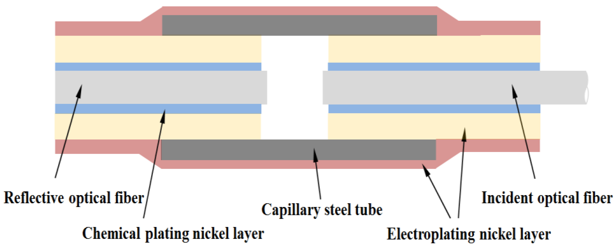
Figure 1. Structure diagram of the EFPI sensor.
Coatings 10 01174 g001
Figure 2. Outview of the chemical plated optical fiber.
Coatings 10 01174 g002
Figure 3. Outview of the electroplated optical fiber.
Coatings 10 01174 g003
Figure 4. Schematic diagram of the EFPI sensor electroplating setup based on the in-situ electroplating method.
Coatings 10 01174 g004
Figure 5. Outview of the EFPI sensor: (a) General view of the EFPI sensor; (b) Stereomicroscopegraph of the EFPI sensor.
Coatings 10 01174 g005
Figure 6. The setup of the high-temperature sensing system.
Coatings 10 01174 g006
Figure 7. Reflection spectra changes of the EFPI sensors during the in-situ electroplating processes: (a) EFPI-1; (b) EFPI-2; (c) EFPI-3.
Coatings 10 01174 g007
Figure 8. Reflection spectra of EFPI sensors at room temperature: (a) EFPI-1; (b) EFPI-2; (c) EFPI-3.
Coatings 10 01174 g008
Figure 9. Reflection spectra of EFPI sensors during the temperature sensing process: (a) EFPI-1; (b) EFPI-2; (c) EFPI-3.
Coatings 10 01174 g009
Figure 10. Curves of average peak difference and temperature of EFPI sensors during the temperature sensing process: (a) EFPI-1; (b) EFPI-2; (c) EFPI-3.
Coatings 10 01174 g010aCoatings 10 01174 g010b
Table 1. Cavity length (μm) of EFPI-1 at different temperatures.
TemperatureTest-1Test-2Test-3
Heating ProcessCooling ProcessHeating ProcessCooling ProcessHeating ProcessCooling Process
100 °C160.420160.591162.052160.408161.878160.990
200 °C175.830175.300176.669176.327175.078174.765
300 °C196.801196.517195.787195.682196.476195.678
400 °C211.743210.410211.848210.833211.273210.702
Table 2. Cavity length (μm) of EFPI-2 at different temperatures.
TemperatureTest-1Test-2Test-3
Heating ProcessCooling ProcessHeating ProcessCooling ProcessHeating ProcessCooling Process
100 °C176.149176.651177.010177.110177.230176.958
200 °C197.119197.340197.980197.988198.210197.970
300 °C210.291210.789211.121211.196212.210211.988
400 °C224.232224.550224.960225.110225.312224.890
Table 3. Cavity length (μm) of EFPI-3 at different temperatures.
TemperatureTest-1Test-2Test-3
Heating ProcessCooling ProcessHeating ProcessCooling ProcessHeating ProcessCooling Process
100 °C191.031190.845191.141191.246192.041191.822
200 °C203.268202.227203.048202.602202.963201.856
300 °C215.106214.613215.820214.470216.285214.991
400 °C231.875230.390231.237230.551231.146230.878
Table 4. The linearity of the curves of the average peak difference and temperature of EFPI-1, EFPI-2 and EFPI-3.
EFPI SensorTest-1Test-2Test-3
Heating ProcessCooling ProcessHeating ProcessCooling ProcessHeating ProcessCooling Process
EFPI-10.998670.998630.997960.998740.998850.99872
EFPI-20.997650.997710.998520.998640.997960.99871
EFPI-30.998540.998610.998640.998670.998920.99892
Publisher’s Note: MDPI stays neutral with regard to jurisdictional claims in published maps and institutional affiliations.