Article

Dynamic Contact Analysis of the Piston and Slipper Pair in Axial Piston Pump

1
College of Mechanical Engineering, Yangzhou University, Yangzhou 225127, China
2
School of Automobile and Traffic Engineering, Hefei University of Technology, Hefei 230009, China
*
Author to whom correspondence should be addressed.
Coatings 2020, 10(12), 1217; https://doi.org/10.3390/coatings10121217
Submission received: 28 October 2020 / Revised: 28 November 2020 / Accepted: 11 December 2020 / Published: 13 December 2020

Abstract

:
The dynamic analysis model of axial piston pump was established; both the kinematics and dynamics simulation analysis were conducted by virtual prototyping approach. The displacement, velocity, acceleration and stress curves of the piston under different working conditions were investigated. In addition, a ball-in-socket contact model was established, and the effects of hydraulic pressure, piston radius and radial clearance on normal displacement, contact radius, maximum contact pressure, normal contact stiffness and tangential contact stiffness were analyzed comprehensively. The results indicate that the normal displacement, maximum contact pressure, contact radius, normal contact stiffness and tangential contact stiffness can be improved by enlarging the piston radius and decreasing the radial clearance.

1. Introduction

The high pressure trend of hydraulic transmission makes the utilization of piston pump more and more widely [1]. Axial piston pump has the advantages of high efficiency, stable reliability, high output pressure and compact structure, which is widely used in hydraulic system as the power source. It is more suitable for mobile equipment and automatic control system, especially with the rapid development of construction machinery, mining metallurgy and machine tool equipment [2,3,4,5]. However, due to the mechanical vibration and harsh hydraulic impact during operation, it is easy to cause failure and even cause equipment damage. It has a great demand for long life, high performance and low noise axial piston pump. Therefore, to monitor the axial piston pump operation condition, it is essential to analyze the dynamic characteristics of motion parts [6,7,8,9,10,11].
Guan [12,13,14,15] utilized the fractal theory to study the conformal contact between piston and cylinder block in spherical pump, investigated the effects of structural parameters such as piston radius, radial clearance and material properties on the contact coefficient. The results showed that the normal contact stiffness can be improved by increasing the piston radius, material hardness, reducing the radial clearance and friction coefficient; Gaston [16] conducted research on the reasons, and solutions to deformation and fracture that leads to the loss of performance of the axial pistons pump, and proposed some suggestions to improve the life span of axial piston machines; Shi [17] researched the tangential contact stiffness of cylindrical asperities. A microanalysis model was developed and the tangential contact stiffness of elliptically parabolic asperities on the contact surface was determined. Numerical results showed that the tangential contact stiffness of asperities is determined by material properties, applied loads, fractal dimension, and surface shape; Li [18] established the thermodynamic model of WLAP, which includes the heat generation of pairs and the heat conduction of water and air. The calculation results showed that the water temperature of WLAP exceeded 90 °C and the pump could not work normally in extreme conditions; Lyu [19] proposed a wear prediction method of the piston/cylinder pair by coupling the load-bearing and lubrication parameters calculation model and the wear calculation model. The results indicate that the wear of two ends of the cylinder bore is severe in the specific ranges of circumferential angle; Xu [20] proposed the design parameters of piston pair are important factors affecting the pump pressure level, and properly reducing the oil film thickness can reduce the piston pair leakage and friction loss.
By summarizing the above-mentioned research, two challenging issues exist in the axial piston pump. The presented model cannot consider the force of friction pair under different working conditions and the elastic deformation of spherical pair. Specifically, the existing research studies only focus on the force of friction pair under a certain fixed speed and hydraulic pressure, and lacks the comparative analysis of the force of friction pair under different speed and hydraulic pressure. There is also a lack of specific analysis of the key structural parameters affecting the elastic deformation of the spherical pair. The paper is organized as follows: the structure and working principle of the axial piston pump are presented in Section 2. Energy conversion is realized by rotating components, which are composed of shaft, cylinder block, piston, slipper and retainer. Kinematics model of axial piston pump is presented in Section 3. The relative motion property between cylinder block and piston is proposed and the related virtual prototype model of axial piston pump is established in Section 4. The kinematics and dynamics simulation analysis of axial piston pump are carried out, and the displacement, velocity, acceleration and stress curves of the main parts under different working conditions are investigated. The contact analysis of axial piston pump is presented in Section 5. A ball-in-socket contact model is established, and the influences of hydraulic pressure, piston radius and radial clearance on normal deformation, contact radius, maximum contact pressure, normal contact stiffness and tangential contact stiffness are analyzed by contact theory. Conclusions are presented in Section 6.

2. Structure and Working Principle of Axial Piston Pump

Figure 1 shows high pressure fluid pulsation test bench, which consists of a servo motor with 1.5 kW, the dynamic torque transducer, the data acquisition system and axial piston pump. The servo motor, torque sensor and axial piston pump are fixed on the test table in turn. The servo motor is connected to the input shaft of the torque sensor through a transmission shaft, the output shaft of torque sensor is connected to the axial piston pump, and the transmission shafts are connected to each other through the coupling.
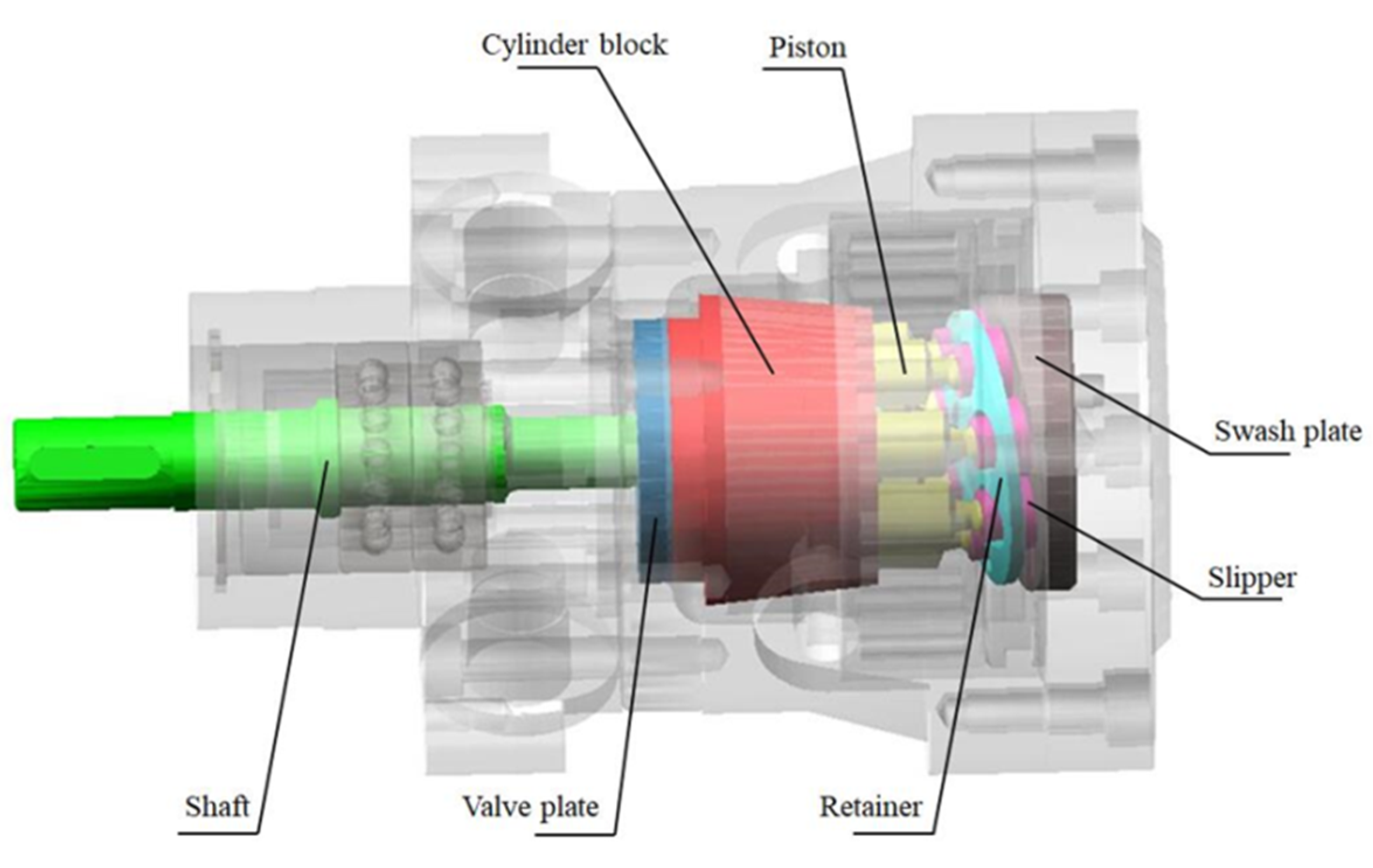
In this paper, the tested axial piston pump is considered as the research object, and its overall configuration is illustrated in Figure 2.
The main structural parts of axial piston pump consist of shaft, swash plate, slipper, piston, cylinder block, valve plate and retainer. The axes of cylinder block and shaft coincide. The swash plate and the valve plate are fixed and the shaft drives the cylinder block to rotate. The piston is arranged axially in the cylinder block, and the slipper is pressed on the swash plate under the action of the retainer. The angle between the normal line of the swash plate and the axis of the cylinder block constitutes the inclination angle of the swash plate [21].
Energy conversion is realized by rotating components, which are composed of different parts, such as shaft, cylinder block, piston, slipper and retainer. The shaft is driven by a servo motor and its speed is set. When shaft rotates, the cylinder block is driven to rotate by splines. The cylinder block drives the piston to perform reciprocating motion along the direction of the shaft and rotate around the pump axis. At the same time, the retainer pushes the slipper to cling to the swash plate under the action of preload, so that the slipper can keep reasonable contact with the inclined plane of the swash plate. When the shaft drives the cylinder block to rotate, the oil enters and exits through the valve plate port [21,22,23].
When the piston moves to the inlet port, each piston extends from the cylinder block and working medium is absorbed into the piston chamber. When the piston operates through the outlet port, each piston is compressed into the cylinder block, and the working medium is squeezed out from the chamber. Each piston chamber suctions and extrudes oil periodically through the inlet and outlet port on the valve plate. This action is repeated in each rotation of the shaft to complete the energy conversion [20,24,25].

3. Kinematics Model of Axial Piston Pump

As shown in Figure 3, the key component of axial piston pump consists of piston, slipper, swash plate and cylinder block. The seven pistons evenly distributed in the cylinder block rotate around the pump axis, and each piston is equipped with a slipper, and the retainer presses the slippers on the swash plate with an inclination angle to the axis.
The inclined angle of swash plate is γ , motion time is t, and the rotational angular velocity of cylinder block is ω . When the piston rotates from the maximum extension position A (i.e., top dead center) to position B, the turning angle of cylinder block is φ = ω t .
The origin point is as shown in Figure 3, then the distance that the center point of piston ball head moves on the ox axis (i.e., coincides with the central axis of the shaft) [26]:
s = R tan γ cos φ
where R is the radius of piston distribution circle; γ is the inclined angle of swash plate; φ is the angle of cylinder block.
The center coordinate of the piston ball head is:
{ x = R tan γ cos φ = R tan γ cos ω t y = R cos φ = R cos ω t z = R sin φ = R sin ω t
where ω is angular velocity; t is motion time.
Equation (1) takes the derivative of time to obtain the velocity of axial movement of piston relative to cylinder block:
v = s ˙ = ω R tan γ sin ω t
Equation (3) takes the derivative of time to obtain the acceleration of axial movement of piston relative to cylinder block:
a = v ˙ = ω 2 R tan γ cos ω t

4. Virtual Prototype Model of Axial Piston Pump

The virtual prototype model of axial piston pump is composed of three-dimensional model and multi-body dynamic model.

4.1. Three-Dimensional Model of Axial Piston Pump

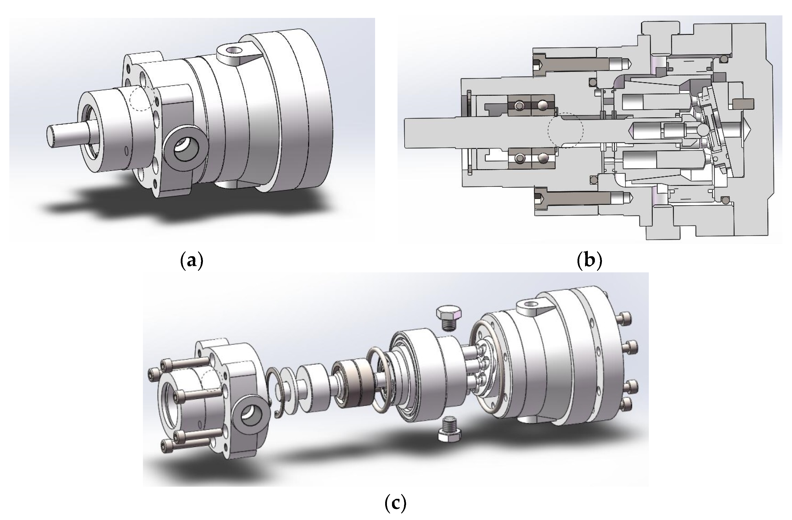
The accurate mapping of the axial piston pump is carried out to obtain the size and assembly mode of each component [27], as shown in Figure 4.

4.2. Multi-Body Dynamic Model of Axial Piston Pump

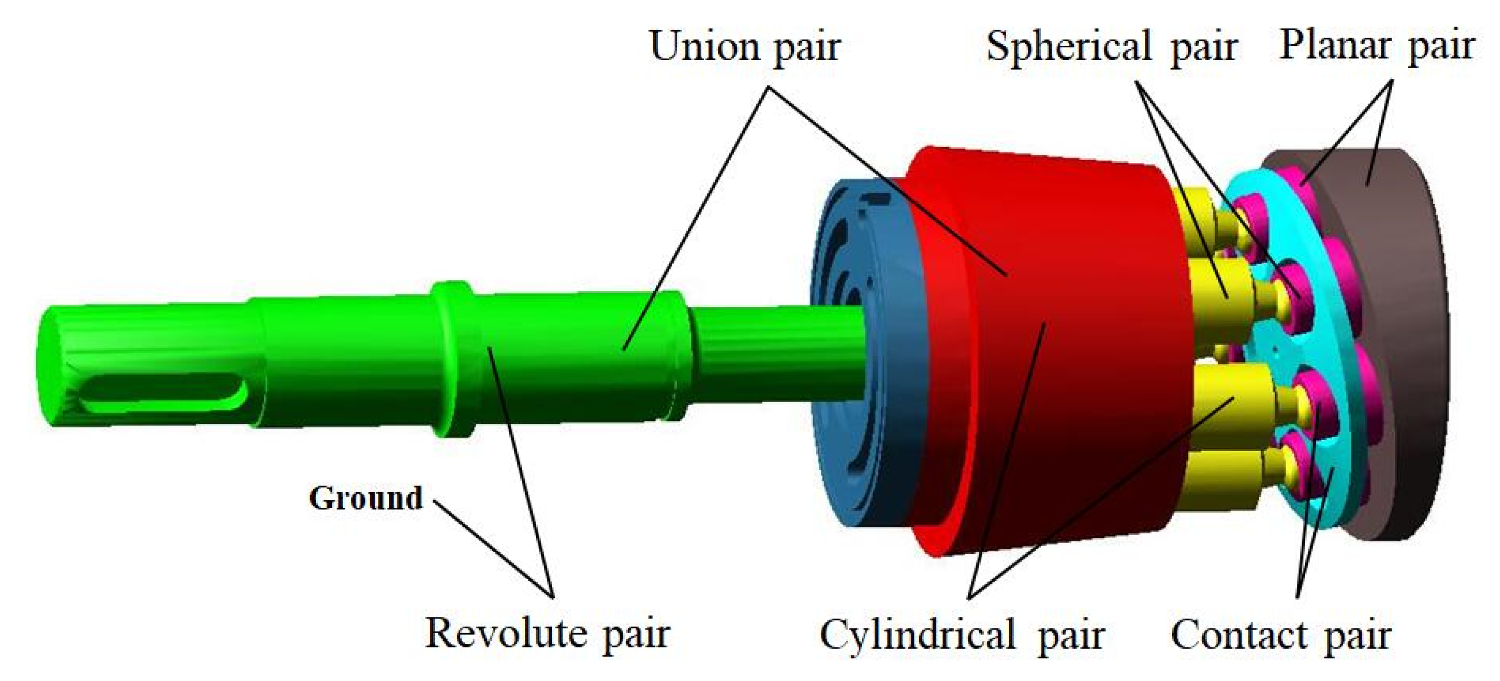
The dynamic model of axial piston pump is simplified, and only the key motion parts are retained, as shown in Figure 5. Add motion constraints to key moving parts, as shown in Table 1.

4.3. Simulation Results of Axial Piston Pump

The kinematics and dynamics simulation analysis of axial piston pump were carried out, and the displacement, velocity, acceleration, force and power of piston are output by post-processing module.

4.3.1. Kinematics Simulation Analysis

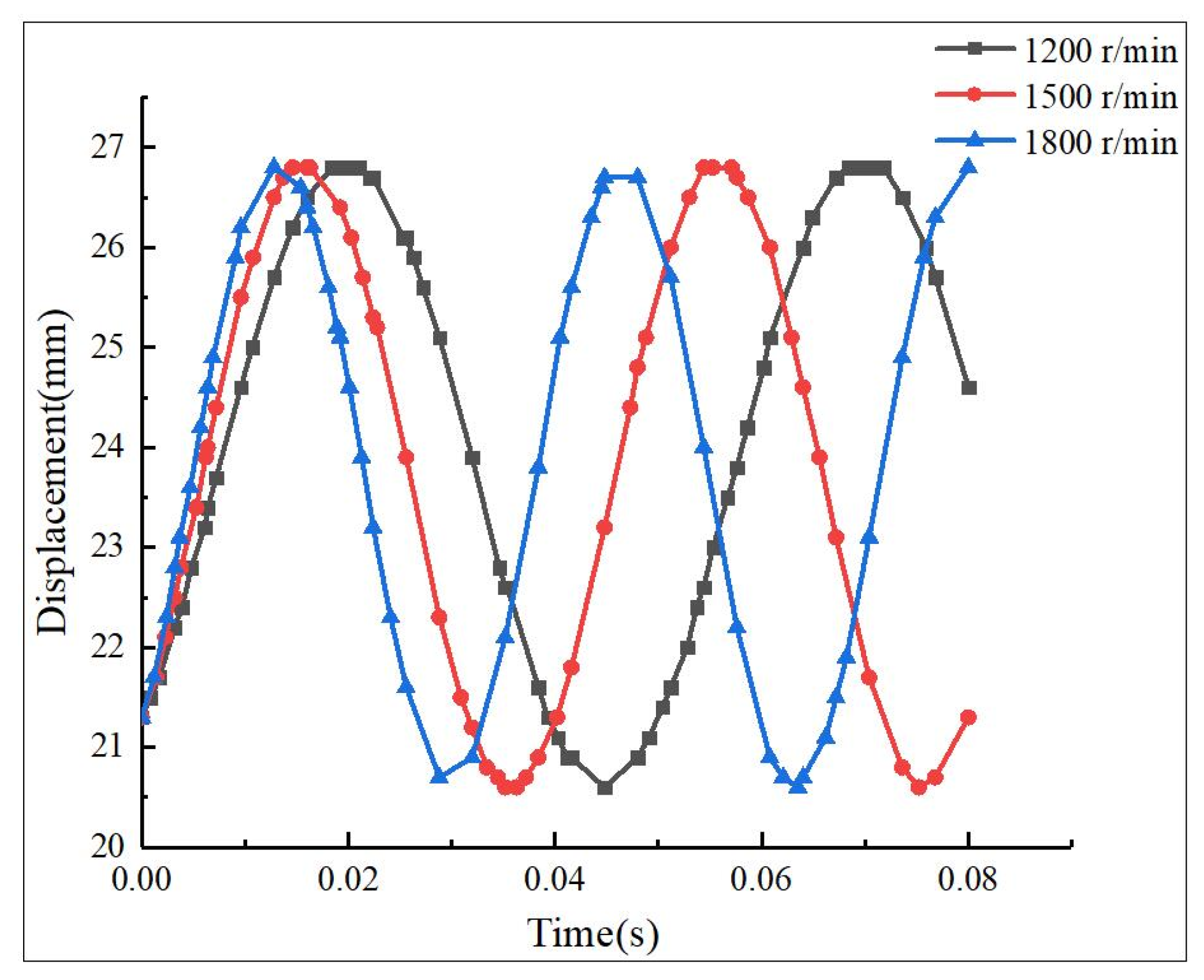
The fixed swash plate angle is 12.5°, the hydraulic pressure is 31.5 MPa, and the rotating speeds are 1200 r/min, 1500 r/min and 1800 r/min respectively, to simulate the movement of axial piston pump under different working conditions [28,29].
It can be seen from Figure 6 that the amplitude of the time-domain displacement hardly varies under different rotating speeds, and the period of the instantaneous displacement decreases with rotation speed. The difference between the maximum displacement and the minimum displacement is 0.0062 m.
The piston velocity is illustrated in Figure 7. The transient velocity of the piston changes periodically under different rotating speeds. When the rotating speed is 1200 r/min, the maximum transient velocity is about 0.39 m/s, and the period of velocity is about 0.049 s. When the rotating speed is 1500 r/min, the maximum velocity is about 0.49 m/s, and the period of velocity is about 0.04 s. When the rotating speed is 1800 r/min, the maximum transient velocity is about 0.59 m/s, and the period is about 0.035 s. With the increase of the rotating speed, the amplitude of the instantaneous velocity of the piston increases sharply, from Vmax = 0.39 m/s at the rotating speed n = 1200 r/min to Vmax = 0.59 m/s at the rotating speed n = 1800 r/min. The period of the instantaneous velocity of the piston was shortened from 0.050 s at the rotating speed n = 1200 r/min to 0.035 s at the rotating speed n = 1800 r/min.
It can be observed from Figure 8 that the transient acceleration of the piston varies periodically as well. The amplitude of the instantaneous acceleration increases with rotating speed, from 49.13 m/s2 under rotating speed n = 1200 r/min, to 77.32 m/s2 under rotating speed n = 1500 r/min, and finally up to 107.25 m/s2 when the rotating speed is 1800 r/min.
Therefore, it can be concluded that the velocity and acceleration of piston varies rapidly with rotation speed, which finally causes obvious inertia force, vibration and collision noise when the motion direction of piston alters.
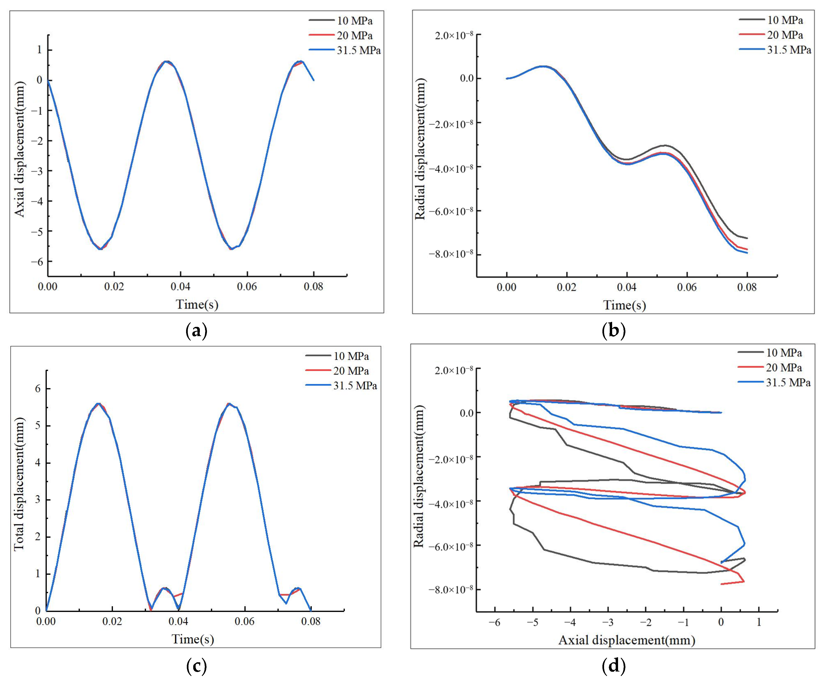
It can be observed from Figure 9a that the period and amplitude of the axial displacement of piston in cylinder block seldom changes under different hydraulic pressures. Difference between the maximum and the minimum axial displacement is 0.006 m, which is at micrometer scale. Figure 9b shows that the radial displacement of piston in cylinder increases with hydraulic pressure, and the curves 20 MPa and 31.5 MPa are much closer than curves 10 MPa and 20 MPa. Since the rigid body is used as the analysis object, and the piston and its matching parts are actually elastomers, it can be inferred that the radial displacement of piston in the cylinder block will be larger in the actual situation. Figure 9c shows that the total displacement of the piston in the cylinder block changes periodically with a period of 0.04 s. Due to the existence of radial displacement, the total displacement does not completely conform to the simple harmonic motion.
It can be inferred that due to the combined influence of the piston centrifugal force and oil pressure in the process of movement, the piston and cylinder block axis is not parallel, and there is a certain deviation and tilt [30].

4.3.2. Dynamic Simulation Analysis

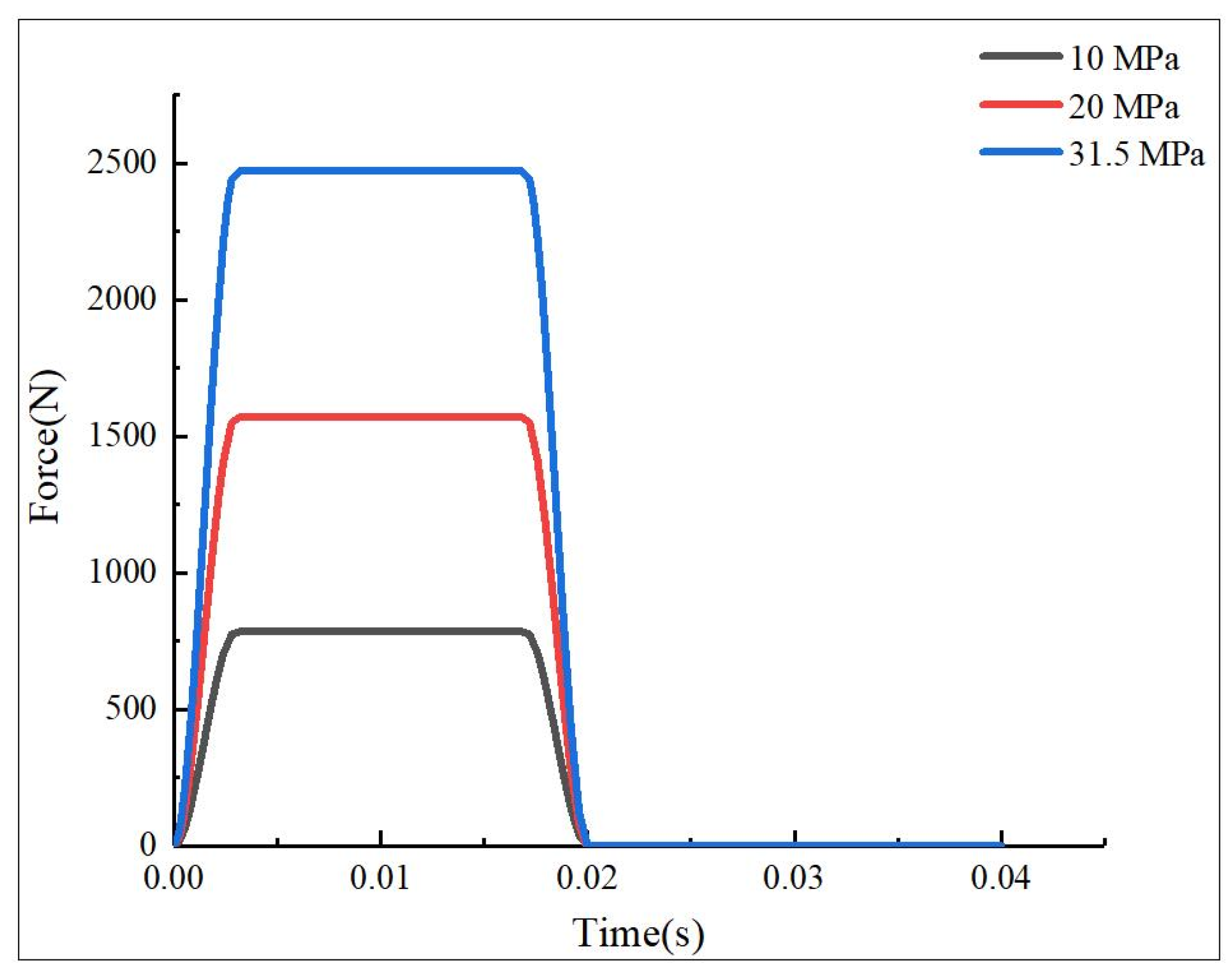
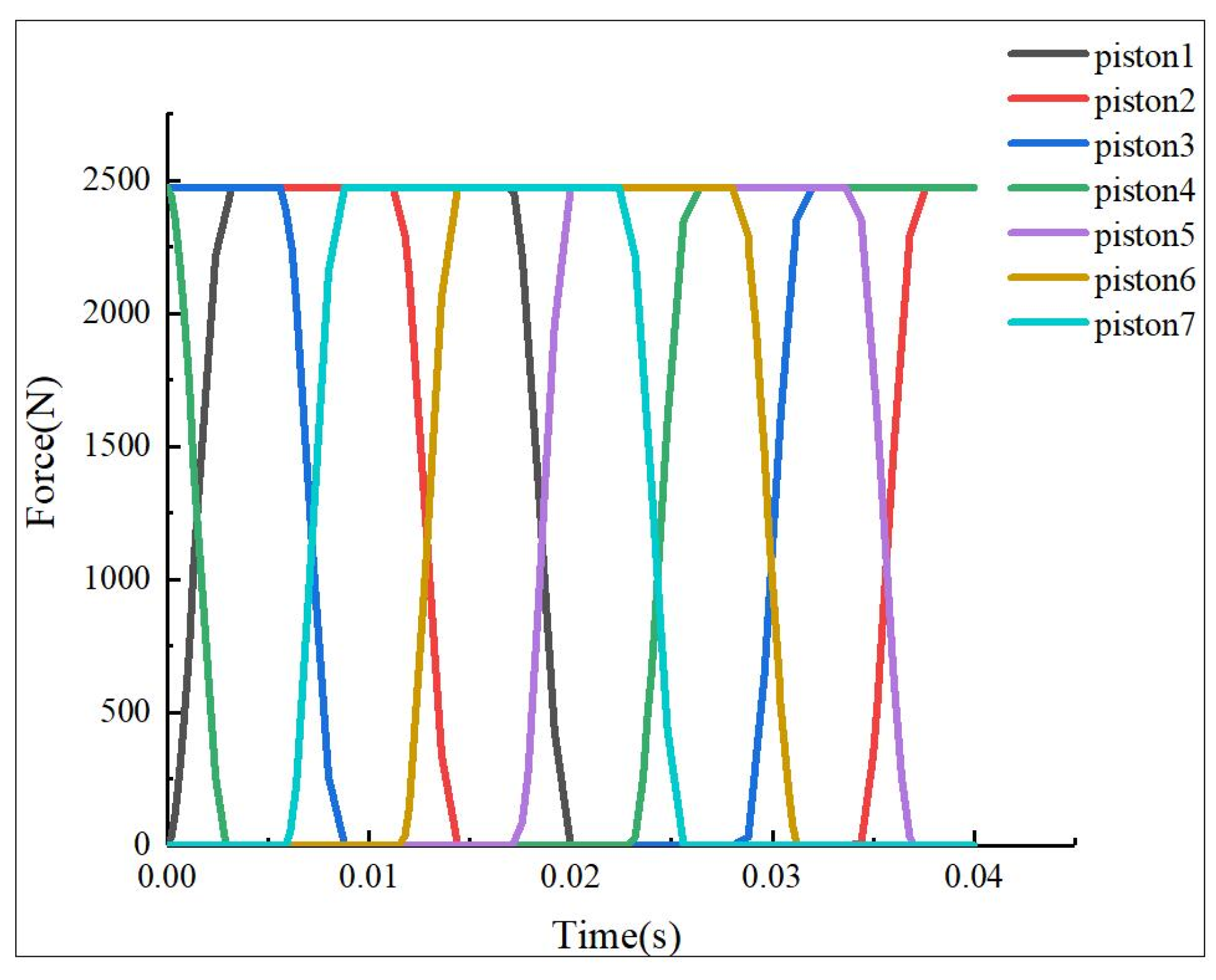
The STEP function is utilized as the driving function, which is consistent with the practical operating logic, as shown in Figure 10. During the operation of the seven pistons, the motion and force of each piston follow the same periodic rule, but the initial phase is different. Hydraulic pressure of the same magnitude and direction is added to the bottom of seven pistons in turn, except that the action time of hydraulic pressure at the bottom of each piston is different. The hydraulic force situation at the bottom of the seven pistons is obtained, as shown in Figure 11.
During the periodic operation of the axial piston pump, all parts bear large loads, among which the main stressed components are spherical pair, slipper pair and piston pair. Because the spherical pair, slipper pair and piston pair of axial piston pump operate under complex working conditions of high pressure and high speed for a long time, these three friction pairs are the key to affect the performance of axial piston pump; that is, the flow characteristics and pressure characteristics of the axial piston pump [31].
Friction and wear are the main causes to decrease the load-carrying capacity of axial piston pumps, such as the spherical pair, slipper pair and piston pair, and can result in low reliability and low service time [25].
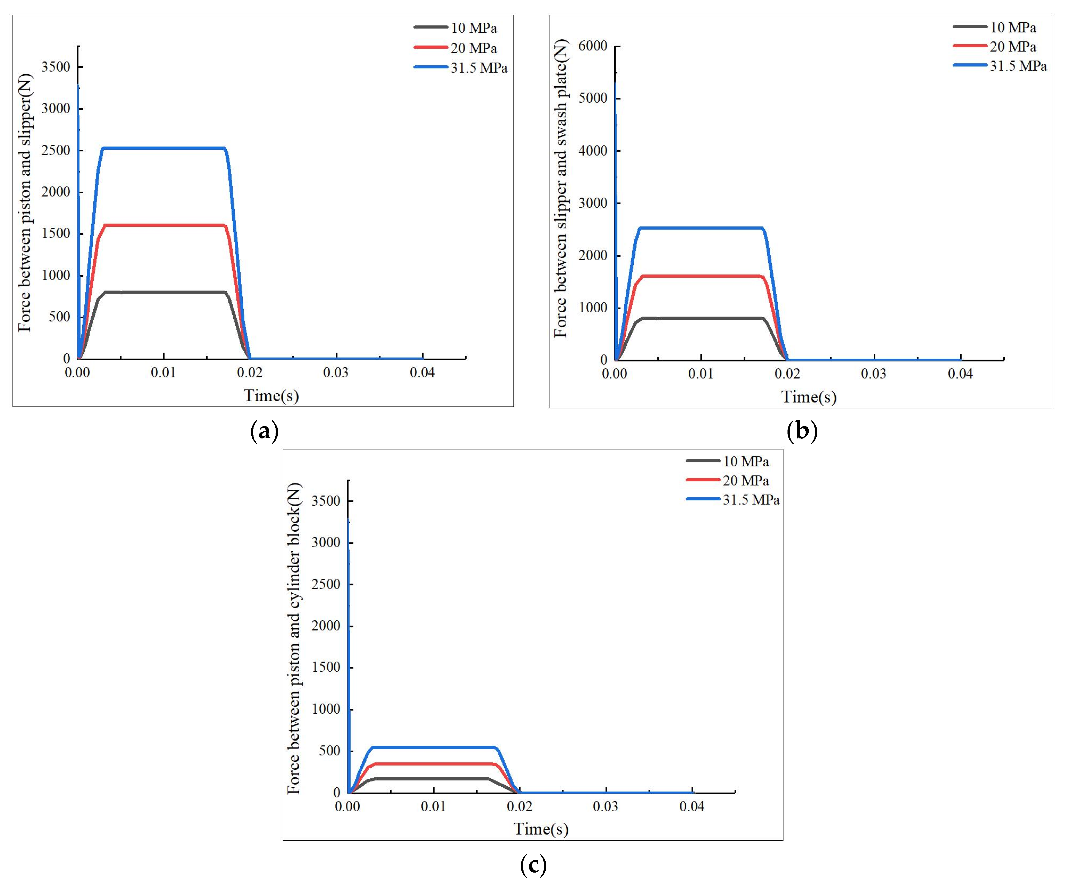
Figure 12 is a comparison of the three friction pairs under the conditions of 10 MPa, 20 MPa and 31.5 MPa, respectively. In a cycle, the contact force of spherical pair, slipper pair and piston pair increase obviously with hydraulic pressure. When the hydraulic pressure is 31.5 MPa, the maximum contact forces of spherical pair, slipper pair and piston pair are 2533 N, 2533 N and 550 N respectively. When the hydraulic pressure is 10 MPa, the minimum contact forces of spherical pair, slipper pair and piston pair are 804 N, 804 N and 174 N respectively. As the hydraulic pressure increases, the force of three friction pairs increases almost linearly with a constant growth rate.
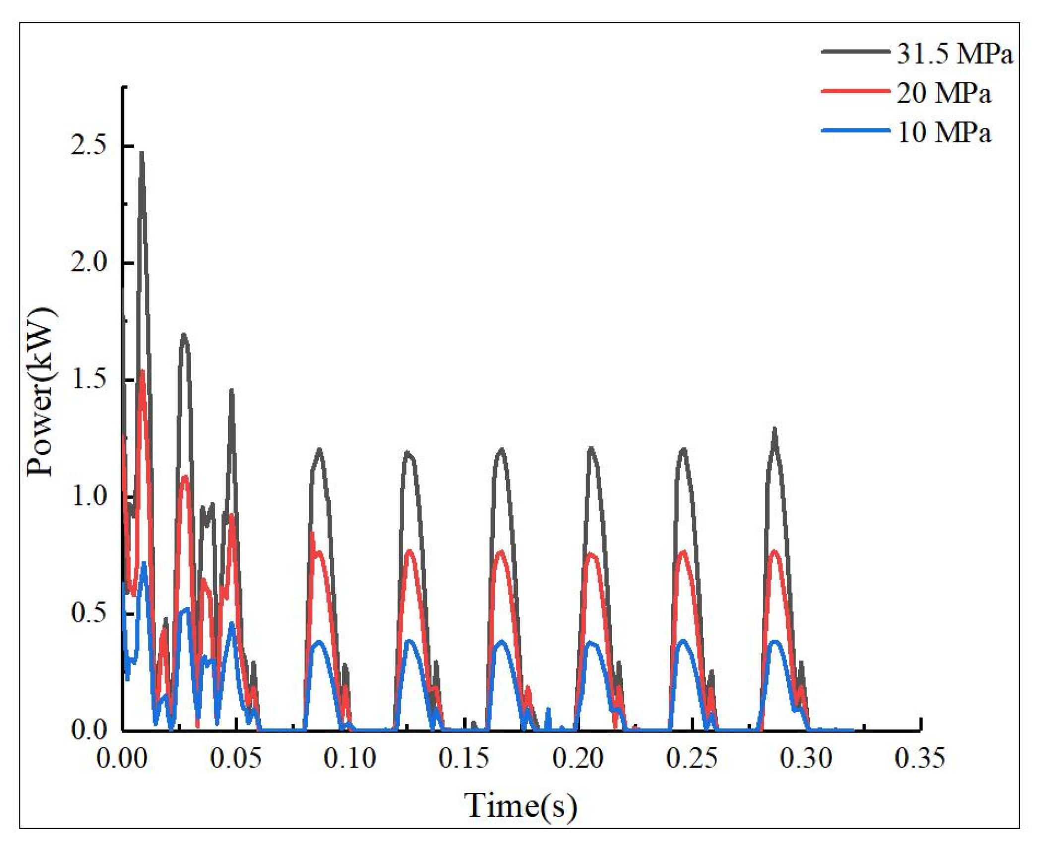
The total power of axial piston pump is shown in Figure 13. The total power of axial piston pump increases with the hydraulic pressure and demonstrates a periodic variation principle. The total power consumption reaches its maximum value at the start moment; it can be inferred that the mechanical system is static at the beginning, and the maximum static friction force needs to be overcome. When the pump operates at a constant speed after starting, the system only needs to overcome the stable dynamic friction force and operates relying on the inertial forces. When the system works stably, the maximum power consumption is about 1.25 kW.
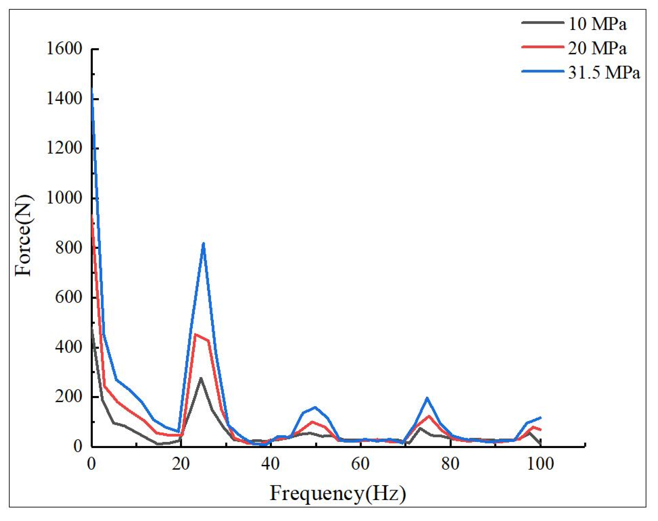
The Fourier transform of the pressure on the pump body of axial piston pump is shown in Figure 14. The rotational speed is 1500 r/min, and a large pulse occurs at 25 Hz, with the corresponding time being 0.04 s [31].

5. Contact Analysis of Axial Piston Pump

The spherical pair is utilized to connect the piston and slipper. The configuration is illustrated in Figure 15. Once the force of the spherical pair is unbalanced or varies abnormally, piston wear accelerated. The failure mode is relatively common in operation, and it also has certain damage to other parts. It should be avoided as far as possible in the design and application process [32]. Both piston and slipper materials are considered as stainless steel, whose elastic modulus and Poisson ratio are E1 = E2 = 200 GPa, ν1 = 0.25, ν2 = 0.3 [15].

5.1. Normal Contact Analysis

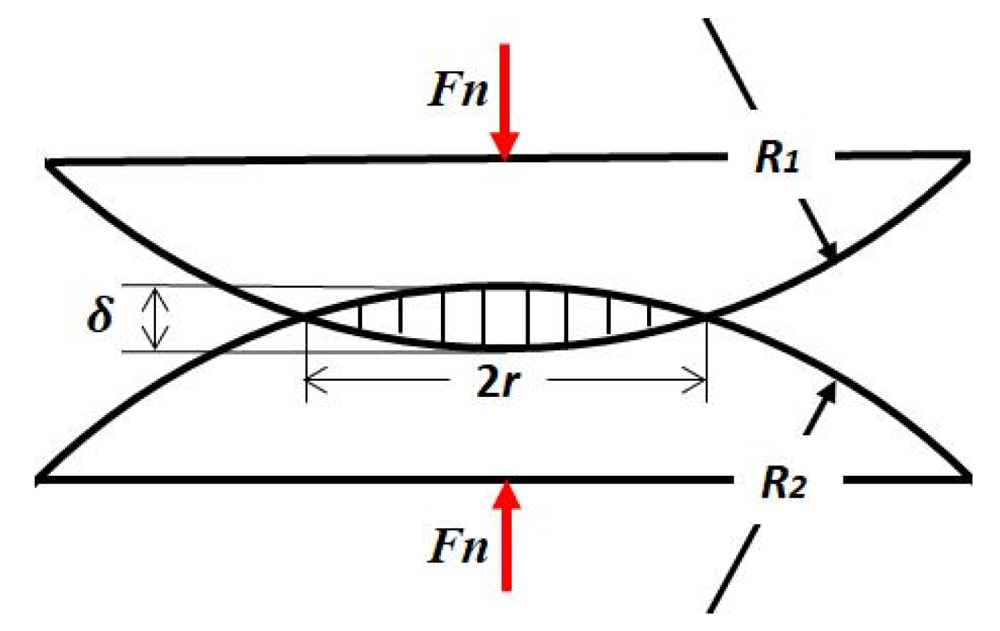
Figure 16 shows the contact model of two asperity bodies, whose radii are R1 and R1 respectively. A normal force Fn is applied on the two contact bodies, therefore a contact area with radius r and normal deformation δ occurs. Based on Hertz theory, they can be expressed as [12]:
δ = ( 9 F n 2 16 R e f f E e f f ) 1 / 3
r = ( 3 F n R e f f 4 E e f f ) 1 / 3
p 0 = ( 6 F n E e f f π 3 R e f f 2 ) 1 / 3
a = π r 2
where δ denotes the normal displacement; Fn represents the normal force; r is contact radius; p0 indicates the maximum contact pressure; a represents area of the contact region.
Reff and Eeff are the effective radius and elastic modulus:
1 R e f f = 1 R 1 ± 1 R 2
1 E e f f = 1 ν 1 2 E 1 + 1 ν 2 2 E 2
where E1, E1, ν1 and ν1 are elastic modulus and Poisson’s ratio of the two contact bodies. It should be mentioned that “+” represents the external contact, while “−” denotes the ball-in-socket internal contact and R1 > R1 in Equation (9). The normal contact stiffness of a single asperity can be obtained by Equations (5), (6) and (8); it is expressed:
k n = d F n d δ = 2 E e f f a π
Figure 17 illustrates the variation of normal displacement δ calculated by Equation (5). Piston radius R1 varies from 0 to 30 mm, while radial clearance ΔR increases from 0 to 0.03 mm. From this, we can infer that slipper radius R2 varies from 0 to 30.03 mm. System pressures are 10, 20 and 31.5 MPa respectively. From the comparison of Figure 17a–c, the normal displacement δ increases with the system pressure. As the piston radius R1 decreases and the radial clearance ΔR increases, the normal displacement δ increases nonlinearly with a rising growth rate.
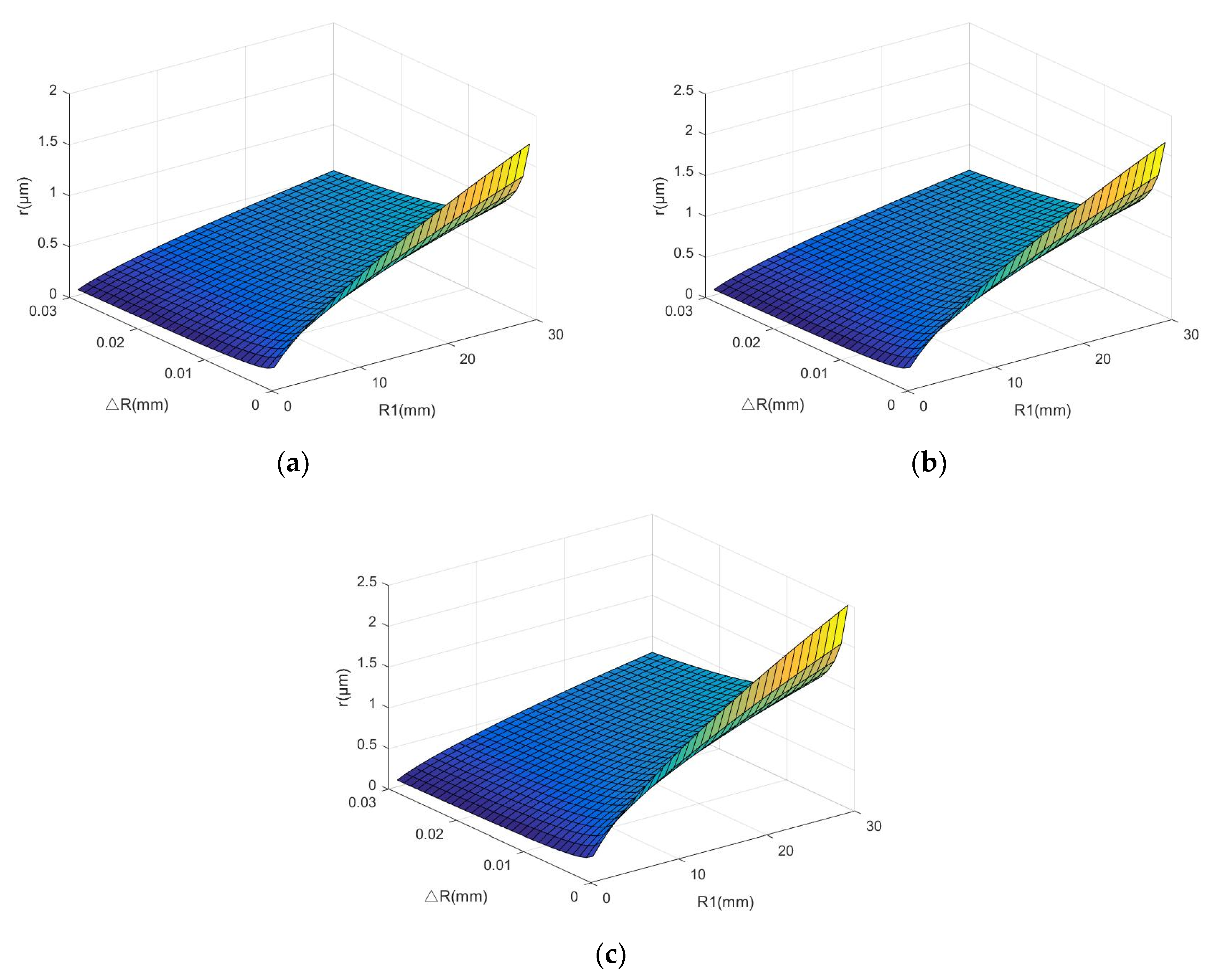
The effects of radial clearance ΔR and piston radius R1 on contact radius r are illustrated in Figure 18. From the comparison of Figure 18a–c, the contact radius r increases with the hydraulic pressure. When the hydraulic pressure is 31.5 MPa, the largest piston radius, R1 = 30 mm, and the smallest radial clearance, ΔR = 0.001 mm, have the maximum contact radius r, while the minimum contact radius r occurs when R1 = 1 mm and ΔR = 0.03 mm.
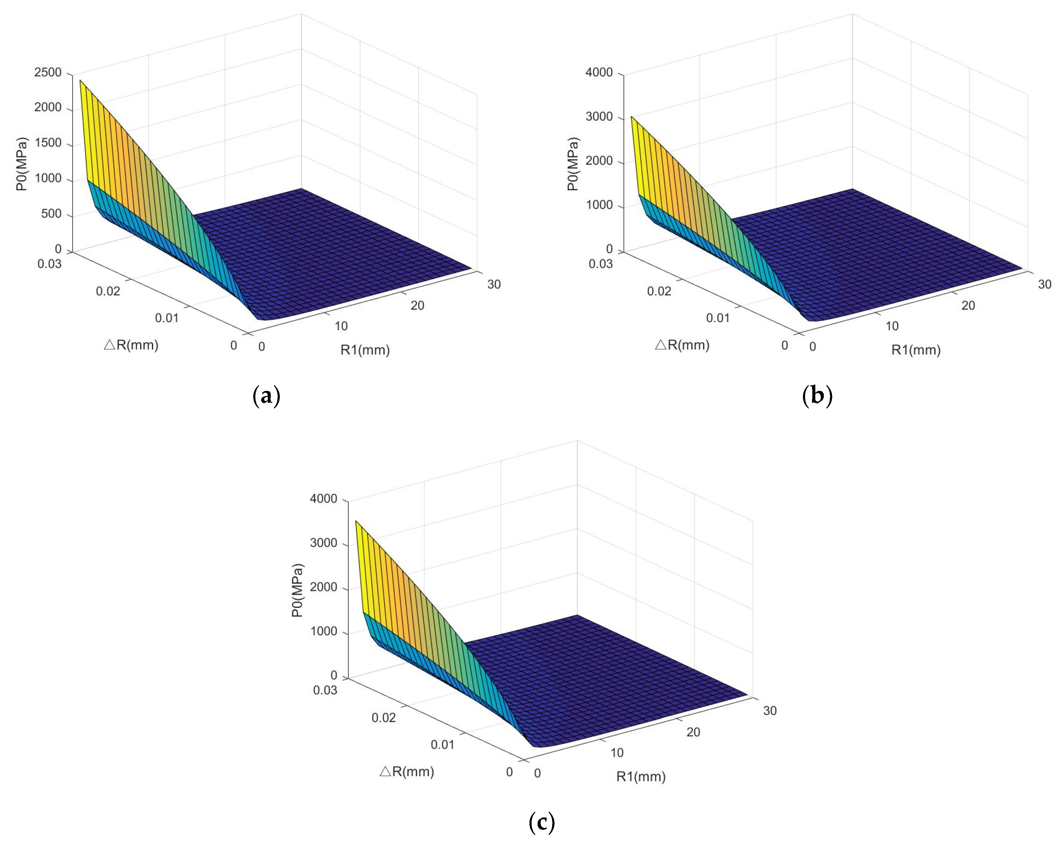
Effects of the radial clearance ΔR and piston radius R1 on maximum contact pressure p0 are shown in Figure 19, in which the three hydraulic pressures are 10, 20 and 31.5 MPa respectively. First, maximum contact pressure p0 increases with radial clearance ΔR, while it decreases with piston radius R1 under the proposed parameters. Besides, it increases with hydraulic pressure—the larger the hydraulic pressure, the stiffer is maximum contact pressure p0.
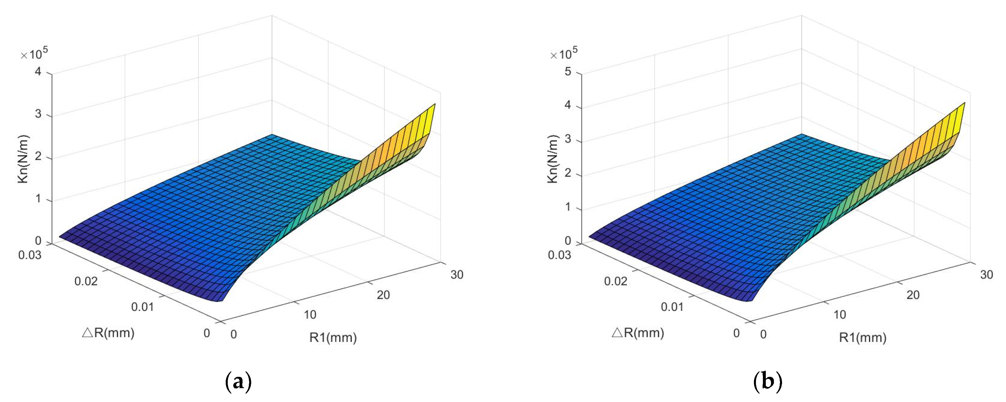
Figure 20 depicts the normal contact stiffness kn variation with piston radius R1 and radial clearance ΔR. These key structural parameters affect the working capacity, internal leakage, efficiency, wear and sound performances [15]. The smallest kn exists when R1 = 1 mm and ΔR = 0.03 mm, which are the smallest piston radius and the largest radius clearance in Figure 20. Then, kn increases with piston radius R1 while decreases with radial clearance ΔR. The kn increases rapidly at a smaller ΔR and a larger R1. Therefore, the largest kn is up to 5.5 × 10⁵ N/m when R1 = 30 mm and ΔR = 0.001 mm.

5.2. Tangential Contact Analysis

The equivalent contact model between piston and cylinder is demonstrated in Figure 21a. In Figure 21b, a normal force Fn is applied leading to the normal displacement δ; radius of the contact region is denoted by r. Besides the normal force Fn, a tangential force Ft which is parallel to the x direction is loaded. The tangential force Ft leads to the tangential deformation t, as illustrated in Figure 21c. The relationship between tangential force Ft and displacement t can be shown as follows [15]:
t = 3 ( 2 ν ) 16 G e r μ F n { 1 [ 1 F t μ F n ] 2 3 }
where μ is the static friction coefficient; Ge denotes the equivalent shear modulus of the two contact surfaces, it is defined as [15]:
G e = E e f f 2 ( 1 + ν )
where ν = V 1 ν 1 + V 2 ν 2 ; V1 and V1 represent the volume fractions of piston and cylinder materials in the contact region, V 1 + V 2 = 1 ; Therefore, the tangential contact stiffness can be defined:
k t = d F t d t = 8 G e r 2 ν [ 1 16 G e r t 3 ( 2 ν ) μ F n ] 1 2
Substituting Equation (12) into Equation (14), then obtain
k t = 8 G e r 2 ν ( 1 1 μ F t F n ) 1 3
Therefore, all the parameters of equivalent shear modulus Ge, contact radius r, equivalent Poisson’s ratio ν, static friction coefficient μ, normal force Fn, as well as tangential force Ft will affect the tangential contact stiffness kt. It should be mentioned that kt only exists when Ft < μFn, otherwise sliding occurs between the piston and cylinder block.
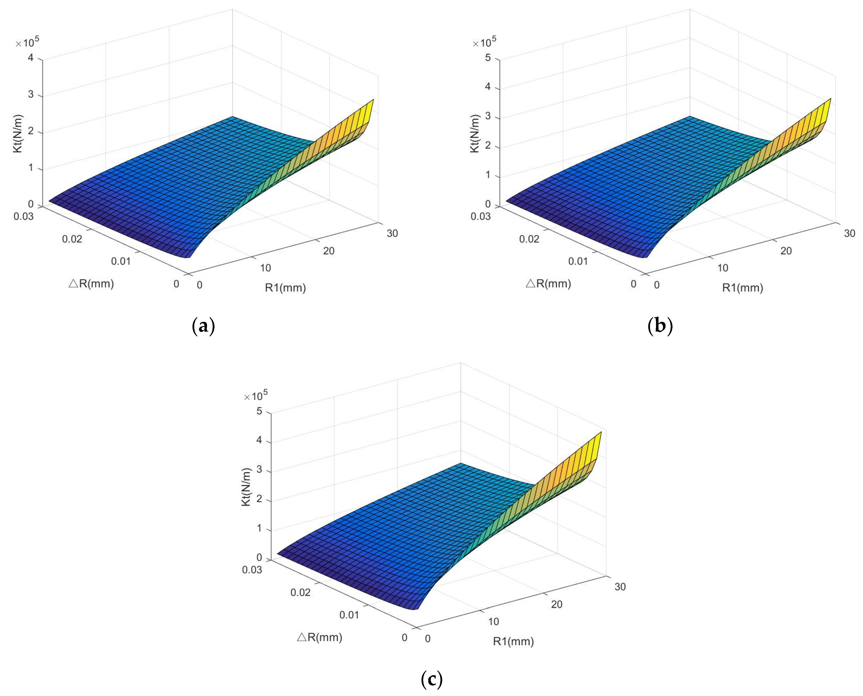
Figure 22 depicts the tangential contact stiffness kt variation with piston radius R1 and radial clearance ΔR. Materials of piston and slipper are still selected as stainless steel, friction coefficient is 0.15. The smallest kt exists when R1 = 1 mm and ΔR = 0.03 mm, which are the smallest piston radius and the largest radial clearance in Figure 22. Then, kt increases with piston radius R1, while it decreases with radial clearance ΔR. The kt increases rapidly at a smaller ΔR and a larger R1. Therefore, the largest kt is up to 4.9 × 10⁵ N/m when R1 = 30 mm and ΔR = 0.001 mm [33,34].

6. Conclusions

Dynamic analysis and contact analysis of axial piston pump are conducted through this paper. Because the existing researches only focus on the kinematic rule and the force of friction pair under a certain fixed speed and hydraulic pressure, this paper makes a comparative analysis under different working conditions, and makes a specific analysis of the key structural parameters that affect the elastic deformation of the spherical pair. On the basis of the proposed theoretical investigations, the obtained major conclusions can be drawn:
(1)
The kinematic simulation analysis verifies the correctness of the virtual prototype model of the axial piston pump, which provides a reference for the motion research of the axial piston pump. The main reason for the mechanical vibration and noise of the axial piston pump is the inertial force caused by the rapid variation of the piston velocity and acceleration.
(2)
The dynamic simulation analysis verifies that with the increase of the hydraulic pressure, the radial displacement of the piston in the cylinder block increases, the contact forces on spherical pair, slipper pair and piston pair increase, and the total power of the axial piston pump increases.
(3)
The results of contact analysis show that the normal displacement, maximum contact pressure, contact radius, normal contact stiffness and tangential contact stiffness can be improved by enlarging the piston radius and decreasing the radial clearance.

Author Contributions

Conceptualization, H.S. and D.G.; methodology, L.J.; software, Z.Z. and Z.L.; validation, C.Z., D.G., and Z.Z.; formal analysis, D.G.; resources, H.S. and D.G.; data curation, C.Z.; writing—original draft preparation, Z.Z.; writing—review and editing, D.G.; visualization, Z.Z.; supervision, H.S. and D.G.; project administration, D.G.; funding acquisition, D.G. All authors have read and agreed to the published version of the manuscript.

Funding

This research was funded by Natural Science Foundation of China, grant number 52005433, Jiangsu Province Natural Science Foundation, grant number BK20180933, Natural Science Foundation of Jiangsu Higher Institutions, grant number 19KJB460028, Special Cooperation Foundation for Yangzhou & YZU, grant number 2020182, the Qing Lan Project and the Homemade Instrument Fund from Yangzhou University.

Conflicts of Interest

The authors declare no conflict of interest.

References

  1. Zmen, Z.; Sinanolu, C.; Caliskan, A.; Badem, H. Prediction of Leakage from an Axial Piston Pump Slipper with Circular Dimples Using Deep Neural Networks. Chin. J. Mech. Eng. 2020, 33, 1–11. [Google Scholar] [CrossRef] [Green Version]
  2. Bergada, J.M.; Kumar, S.; Davies, D.L.; Watton, J. A complete analysis of axial piston pump leakage and output flow ripples. Appl. Math. Model. 2011, 36, 1731–1751. [Google Scholar] [CrossRef]
  3. Xu, B.; Hu, M.; Zhang, J.Z.; Mao, Z.B. Distribution characteristics and impact on pump’s efficiency of hydro-mechanical losses of axial piston pump over wide operating ranges. J. Cent. South Univ. 2017, 24, 609–624. [Google Scholar]
  4. D’Andrea, D.; Epasto, G.; Bonanno, A.; Guglielmino, E.; Benazzi, G. Failure analysis of anti-friction coating for cylinder blocks in axial piston pumps. Eng. Fail. Anal. 2019, 104, 126–138. [Google Scholar] [CrossRef]
  5. Deng, H.; Hu, C.; Wang, Q.; Wang, L.; Wang, C. Friction and wear analysis of the external return spherical bearing pair of axial piston pump/motor. Mech. Ind. 2020, 21, 104. [Google Scholar] [CrossRef] [Green Version]
  6. Guan, C.; Jiao, Z.; He, S. Theoretical study of flow ripple for an aviation axial-piston pump with damping holes in the valve plate. Chin. J. Aeronaut. 2014, 27, 169–181. [Google Scholar] [CrossRef] [Green Version]
  7. Guan, D.; Hilton, H.H.; Yang, Z.; Jing, L.; Lu, K. Lubrication regime analysis for spherical pump. Ind. Lubr. Tribol. 2018, 70, 1437–1446. [Google Scholar] [CrossRef]
  8. Gao, D.; Zhang, Z.; Sun, Y.; Xu, S.; Liu, J.; Zhang, Y. Numerical simulation and analysis of temperature and flow field of high-speed axial piston motor pump. J. Eng. 2019, 2019, 127–131. [Google Scholar] [CrossRef]
  9. Ye, S.; Zhang, J.; Xu, B.; Zhu, S.; Xiang, J.; Tang, H. Theoretical investigation of the contributions of the excitation forces to the vibration of an axial piston pump. Mech. Syst. Signal Process. 2019, 129, 201–217. [Google Scholar] [CrossRef]
  10. Jana, T.; Mitra, A.; Sahoo, P. Unloading analysis of elastically and plastically graded hemispherical contact with rigid flat. Tribol. Int. 2020, 142, 105973. [Google Scholar] [CrossRef]
  11. Tang, H.; Ren, Y.; Zhang, X.-l. Tribological performance of MoS2 coating on slipper pair in axial piston pump. J. Cent. South Univ. 2020, 27, 1515–1529. [Google Scholar] [CrossRef]
  12. Guan, D.; Jing, L.; Gong, J.; Shen, H.; Hilton, H.H. Normal contact analysis for spherical pump based on fractal theory. Tribol. Int. 2018, 124, 117–123. [Google Scholar] [CrossRef]
  13. Guan, D.; Jing, L.; Gong, J.; Yang, Z.; Shen, H. Friction and wear modeling of rotary disc in spherical pump. Ind. Lubr. Tribol. 2019, 71, 420–425. [Google Scholar] [CrossRef]
  14. Guan, D.; Jing, L.; Hilton, H.H.; Gong, J. Dynamic lubrication analysis for a spherical pump. Proc. Inst. Mech. Eng. Part J. 2019, 233, 1–12. [Google Scholar] [CrossRef]
  15. Guan, D.; Jing, L.; Hilton, H.H.; Gong, J.; Yang, Z. Tangential contact analysis of spherical pump based on fractal theory. Tribol. Int. 2018, 119, 531–538. [Google Scholar] [CrossRef]
  16. Haidak, G.; Wang, D.; Awong, E.L.E. Modelling of deformation and failure of slipper-retainer assembly in axial piston machine. Eng. Fail. Anal. 2020, 111, 104490. [Google Scholar] [CrossRef]
  17. Shi, J.; Cao, X.; Zhu, H. Tangential Contact Stiffness of Rough Cylindrical Faying Surfaces Based on the Fractal Theory. J. Tribol. 2014, 136, 041401. [Google Scholar] [CrossRef]
  18. Li, D.; Li, G.; Han, J.; Liu, Y.; Wu, D. Thermodynamic characteristics research of a water lubricating axial piston pump. Proc. Inst. Mech. Eng. Part C 2020, 234, 3873–3889. [Google Scholar] [CrossRef]
  19. Lyu, F.; Zhang, J.; Sun, G.; Xu, B.; Pan, M.; Huang, X.; Xu, H. Research on wear prediction of piston/cylinder pair in axial piston pumps. Wear 2020, 456–457. [Google Scholar] [CrossRef]
  20. Pan, Y.; Li, Y.; Liang, D. The influence of dynamic swash plate vibration on outlet flow ripple in constant power variable-displacement piston pump. Proc. Inst. Mech. Eng. Part C 2019, 233, 4914–4933. [Google Scholar] [CrossRef]
  21. Wu, H.; Zhao, L.; Ni, S.; He, Y. Study on friction performance and mechanism of slipper pair under different paired materials in high-pressure axial piston pump. Friction 2020, 8, 957–969. [Google Scholar] [CrossRef] [Green Version]
  22. Nagatani, H.; Imou, A. Contact Pressure and Shear Stress Analysis on Conforming Contact Problem. J. Adv. Mech. Des. Syst. Manuf. 2008, 2, 1055–1066. [Google Scholar] [CrossRef] [Green Version]
  23. Wang, S.; Xiang, J.; Zhong, Y.; Tang, H. A data indicator-based deep belief networks to detect multiple faults in axial piston pumps. Mech. Syst. Signal Process. 2018, 112, 154–170. [Google Scholar] [CrossRef]
  24. Xu, B.; Hu, M.; Zhang, J. Impact of typical steady-state conditions and transient conditions on flow ripple and its test accuracy for axial piston pump. Chin. J. Mech. Eng. 2015, 28, 1012–1022. [Google Scholar] [CrossRef]
  25. Ye, S.; Tang, H.; Ren, Y.; Xiang, J. Study on the load-carrying capacity of surface textured slipper bearing of axial piston pump. Appl. Math. Model. 2020, 77, 554–584. [Google Scholar] [CrossRef]
  26. Guan, D.; Wu, J.H.; Jing, L.; Hilton, H.H.; Lu, K. Kinematic modeling, analysis and test on a quiet spherical pump. J. Sound Vib. 2016, 383, 146–155. [Google Scholar] [CrossRef]
  27. Zhang, J.; Liu, B.; Lv, R.; Yang, Q.; Dai, Q. Study on Oil Film Characteristics of Piston-Cylinder Pair of Ultra-High Pressure Axial Piston Pump. Processes 2020, 8, 68. [Google Scholar] [CrossRef] [Green Version]
  28. Zloto, T. Simulation of the Hydrostatic Load of the Valve Plate-cylinder Block System in an Axial Piston Pump. Procedia Eng. 2017, 177, 247–254. [Google Scholar] [CrossRef]
  29. Złoto, T.; Kowalski, K. Load of the slipper-swash plate kinematic pair of an axial piston pump. Matec Web Conf. 2018, 157, 08013. [Google Scholar] [CrossRef]
  30. Zhang, B.; Ma, J.; Hong, H.; Yang, H.; Fang, Y. Analysis of the flow dynamics characteristics of an axial piston pump based on the computational fluid dynamics method. Eng. Appl. Comput. Fluid Mech. 2017, 11, 86–95. [Google Scholar] [CrossRef] [Green Version]
  31. Ye, S.; Zhang, J.; Xu, B.; Hou, L.; Xiang, J.; Tang, H. A theoretical dynamic model to study the vibration response characteristics of an axial piston pump. Mech. Syst. Signal Process. 2021, 150, 107237. [Google Scholar] [CrossRef]
  32. Zhou, J.; Zhou, J.; Jing, C.; Yuan, S.; Luo, A. Dynamic Characteristics of Lubrication and Wear Prediction of Slipper/Swash-Plate in Axial Piston Pumps. J. Beijing Inst. Technol. 2019, 28, 519–528. [Google Scholar]
  33. Guan, D.; Jing, X.; Shen, H.; Jing, L.; Gong, J. Test and simulation the failure characteristics of twin tube shock absorber. Mech. Syst. Signal Process. 2019, 122, 707–719. [Google Scholar] [CrossRef]
  34. Guan, D.; Wu, J.H.; Jing, L. A statistical method for predicting sound absorbing property of porous metal materials by using quartet structure generation set. J. Alloy Compd. 2015, 626, 29–34. [Google Scholar] [CrossRef]
Figure 1. High pressure fluid pulsation test bench (a) prototype (b) 3D configuration.
Coatings 10 01217 g001
Figure 2. Motion parts in axial piston pump.
Coatings 10 01217 g002
Figure 3. Motion principle between cylinder block and piston.
Coatings 10 01217 g003
Figure 4. Three-dimensional model of axial piston pump (a) isometric side view (b) sectional schematic (c) exploded view.
Coatings 10 01217 g004
Figure 5. Dynamic model of axial piston pump.
Coatings 10 01217 g005
Figure 6. Displacement curve of piston.
Coatings 10 01217 g006
Figure 7. Velocity curve of piston.
Coatings 10 01217 g007
Figure 8. Acceleration curve of piston.
Coatings 10 01217 g008
Figure 9. Displacement of piston in cylinder block. (a) axial displacement (b) radial displacement (c) total displacement (d) radial displacement with respect to axial displacement.
Coatings 10 01217 g009
Figure 10. Bottom pressure of single piston.
Coatings 10 01217 g010
Figure 11. Bottom pressure of 7 pistons.
Coatings 10 01217 g011
Figure 12. The force of friction pair (a) Force between piston and slipper (b) Force between slipper and swash plate (c) Force between piston and cylinder block.
Coatings 10 01217 g012
Figure 13. Total power consumption of the axial piston pump.
Coatings 10 01217 g013
Figure 14. Fourier transform of the pressure on the pump body.
Coatings 10 01217 g014
Figure 15. Piston slipper assembly (a) sectional schematic (b) 3D view.
Coatings 10 01217 g015
Figure 16. Hertz contact model of a single asperity.
Coatings 10 01217 g016
Figure 17. The normal displacement (a) 10 MPa (b) 20 MPa (c) 31.5 MPa.
Coatings 10 01217 g017aCoatings 10 01217 g017b
Figure 18. The contact radius (a) 10 MPa (b) 20 MPa (c) 31.5 MPa.
Coatings 10 01217 g018
Figure 19. The maximum contact pressure (a) 10 MPa (b) 20 MPa (c) 31.5 MPa.
Coatings 10 01217 g019
Figure 20. The normal contact stiffness (a) 10 MPa (b) 20 MPa (c) 31.5 MPa.
Coatings 10 01217 g020aCoatings 10 01217 g020b
Figure 21. Equivalent contact model (a) without load (b) with normal force (c) both normal and tangential force.
Coatings 10 01217 g021
Figure 22. Tangential contact stiffness (a) 10 MPa (b) 20 MPa (c) 31.5 MPa.
Coatings 10 01217 g022
Table 1. Motion constraints.
Constraint PairPart 1Part 2
FixedPump bodyGround
UnionValve platePump body
Swash platePump body
ShaftCylinder block
RevoluteShaftGround
CylindricalPistonCylinder block
SphericalPistonSlipper
ContactSlipperRetainer
PlanarSlipperSwash plate
Publisher’s Note: MDPI stays neutral with regard to jurisdictional claims in published maps and institutional affiliations.