Article

Microstructure and Wear Behavior of Plasma-Sprayed TiO2–SiAlON Ceramic Coating

1
School of Mechanical Engineering, Jiangsu University, 301 Xuefu Road, Zhenjiang 212013, Jiangsu, China
2
National Demonstration Center for Experimental Materials Science and Engineering Education, Jiangsu University of Science and Technology, Zhenjiang 212003, Jiangsu, China
*
Authors to whom correspondence should be addressed.
Coatings 2020, 10(12), 1268; https://doi.org/10.3390/coatings10121268
Submission received: 17 November 2020 / Revised: 15 December 2020 / Accepted: 16 December 2020 / Published: 21 December 2020

Abstract

:
In this study, atmospheric plasma spray was employed to deposit TiO2–SiAlON ceramic coating on 316 stainless steel. The phases and microstructure of the ceramic coating were investigated. Additionally, comparative studies on the tribological performances of the substrate and the ceramic coating, under both dry and starved lubrication conditions, were carried out. The SiAlON phase was preserved, while partial TiO2 anatase was transformed to rutile phase. The wear rate of the coating was roughly 1/3 of that of the substrate under both conditions. The wear mechanisms of the ceramic coating were surface fracture and abrasive wear in both cases, and the coating under starved lubrication underwent less abrasion. The pores in the coating served as micro-reservoirs, forming an oil layer on the mating surface, and improving tribological properties during sliding.

1. Introduction

SiAlON ceramics are promising materials with high strength, good oxidation resistance, excellent wear resistance and chemical corrosion resistance [1,2,3,4]. Based on these properties, SiAlON ceramics seem to be ideal candidates for high-temperature structural and engineering applications such as cutting tool material, attrition milling arms, wire extrusion dies, roll bearings, etc. [5,6,7] Among them, β–SiAlON ceramics described by the formula Si6–zAlzOzN8–z, where Z represents the substitution of Z Si–N bonds by Z Al–O bonds [8], are used under demanding working conditions, such as cutting tools and wear components, due to their high hardness and outstanding wear resistance [9]. In previous studies, β–SiAlON ceramics were prepared by sintering, such as hot pressing [10,11,12] and spark plasma sintering (SPS) [13,14,15,16] of Si3N4, Al2O3 and AlN blended powder. However, sintering is unsuitable for components with complex shapes and large sizes.
As one of the most widely used thermal-spraying techniques, atmospheric plasma spraying (APS) can deposit ceramic coatings on substrate surfaces by spraying melted powders at a high speed using a high-temperature plasma jet [17,18]. For this reason, ceramic coatings deposited by APS have been commonly applied on large metallics or ceramic parts with complex shapes. Seemingly, APS is a good way to deposit SiAlON ceramic coatings. However, Sodeoka et al. [19] investigated the influences of Z on the deposition behavior of SiAlON ceramics by thermal spraying and found SiAlON coatings could only be obtained when Z = 3 or 4, but at a low deposition rate. The main reason for such difficult to deposit properties is the decomposition and sublimation of SiAlON ceramics in the high-temperature plasma. Thus, SiAlON ceramics alone are unsuitable to be the coating material for plasma spraying.
TiO2—which exhibits excellent wear resistance [20,21]—has a relatively low melting point of 2143 K at 0.1 MPa. Theoretically, the spraying power can be adjusted to just melt TiO2, and the liquid TiO2 can wrap solid SiAlON and protect it from being overheated in the spray process, reducing its decomposition and sublimation loss. Expectedly, the composite powder with molten TiO2 and solid SiAlON can be deposited on the substrate.
In this study, TiO2–SiAlON ceramic coating was deposited using APS. The microstructure, wear resistance and wear mechanisms of the ceramic coating were investigated.

2. Materials and Methods

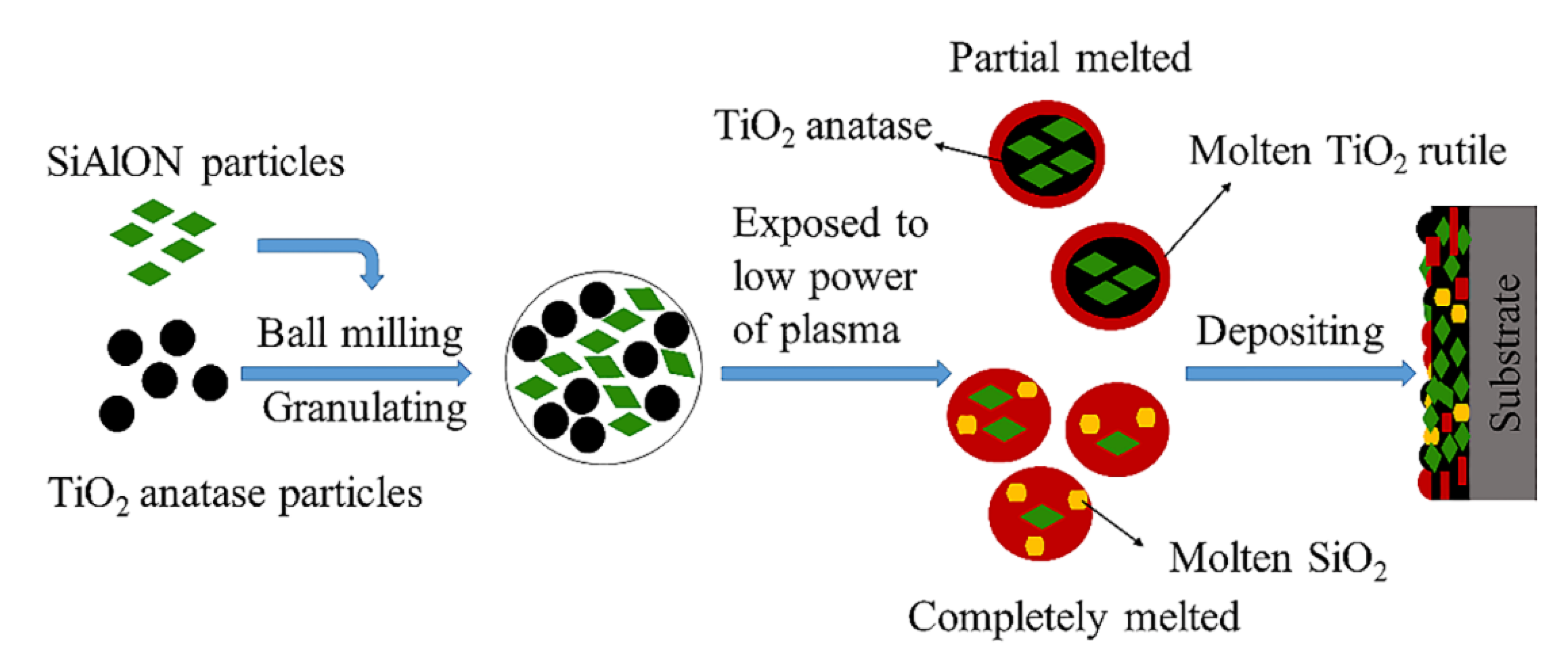
2.1. Preparation of the Feedstock Powder

The β–SiAlON of Z = 1 in the chemical formula Si6–zAlzOzN8–z was chosen for this study because the wear rate and friction coefficient of SiAlON will increase as the Z value increases [16]. Commercially available Si3N4 (Hentai Nonferrous Metal Research Institute, Wuxi, China), Al2O3 (Hentai Nonferrous Metal Research Institute, Wuxi, China) and AlN (Hentai Nonferrous Metal Research Institute, Wuxi, China) were used as raw powder. They were mixed according to the stoichiometric ratio to synthesize Si5AlON7 with the following equation:
( 6 z ) Si 3 N 4 + zAI 2 O 3 + AIN = 3 Si ( 6 z ) AI z O z N ( 8 z )
The powder was homogeneously mixed by planetary ball milling (MITR Instrument Equipment Co. Ltd., Changsha, China) for 16 h in ethyl alcohol using zirconia balls at a ball to sample mass ratio of 10:1. The slurries were then dried in a vacuum evaporator. The samples were sintered in an argon atmosphere at 1700 °C for 3 h; the heating rate was 10 °C/min and the furnace was naturally cooled to room temperature. After crushing and ball milling, the samples were mixed with commercially available TiO2 anatase (Hengan New Materials Technology Co. Ltd., Beijing, China) at the volume ratio of 1:4 by planetary ball milling for 10 h in an argon atmosphere. Then the mixed particles were manually granulated using 5 wt.% organic binder, polyvinyl alcohols (PVA), to improve the flowability. The granulated particles were dried at 100 °C, in vacuum drying oven for 5 h, to remove binder and moisture, prior to spraying. The SEM micrographs and XRD patterns of all as-received powders are given in Figure 1 and Figure 2, respectively. The size of Si3N4, AlN and Al2O3 particles is in the micrometer scale; while that of TiO2 is in the nanoscale. The XRD patterns show that there are no secondary phases present in these particles. In addition, as-received nanocrystalline TiO2 is anatase.

2.2. Preparation of the TiO2–20% SiAlON Ceramic Coating

An atmospheric plasma spraying system (3710, Praxair Surface Technologies, Indianapolis, IN, USA) was used to deposit TiO2–SiAlON coating onto the surface of 316 stainless steel substrate with dimensions of Φ25 × 8 mm. Before plasma spraying, the surfaces of the substrates were grit blasted with corundum sand with an average size of 600 μm for 30 s to promote surface activation and then degreased in an ultrasonic acetone bath. Additionally, the substrates were preheated to 100 °C to improve the adhesion of the coating prior to spraying. The spraying parameters used to deposit the coatings are shown in Table 1.

2.3. Characterization

The microstructure of the feedstock powder and deposited coating was observed using a scanning electron microscope (SEM, S–3400N, Hitachi Incorporation, Tokyo, Japan). The porosity of the coating was measured by an imaging method using software ImageJ. The final result was the average of the data in 10 micrographs. X-ray diffraction (XRD) measurements were conducted by an X-ray diffractometer (D8 advance, Bruker Incorporation, Karlsruhe, Germany), operating with a copper anode at 3 kW and employing a scan rate of 5°min−1 in a scattering angular range (2θ) of 10°–90°.
The tensile adhesion test was conducted to examine the interfacial adhesion strength according to the ASTM–C633 standard [22]. The surface of the coated sample was bonded to that of the uncoated cylinder of the same material and geometry using E–7 glue (Shanghai Research Institute of Synthetic Resins, Shanghai, China). After heat treatment at 100 °C for 3 h to cure the epoxy, the sample was installed on the testing machine, where a linearly increasing tensile load was applied until the uncoated cylinders detached. An adhesion strength test was measured by a CMT5205 electron universal testing machine (MTS Systems Co., Eden Prairie, MN, USA) at a strain rate of 1 mm/min at room temperature. Before the tensile adhesion test, the exposed samples were grit blasted to remove surface oxides. The reported strength was the mean value of 5 samples sprayed with the same parameters.
The wear test was carried out using a ball on disc friction and wear tester (HT–1000, Zhongke Kaihua Science and Technology Development Ltd., Lanzhou, China) in an air environment at room temperature under two conditions: dry friction and starved lubrication. The samples are named after the test conditions, as shown in Table 2. Before the friction and wear tests, the coatings were polished using SiC sandpaper and then polished using diamond slurries down to an average surface roughness (Ra) of 0.7 μm. The S2 and C2 samples were completely immersed in Poly-alpha-olefin (PAO, without additives) for 10 h, and then the surfaces were lightly wiped with oil blotting paper. The counterparts were Si3N4 balls with a diameter of 5 mm. The test was performed with a normal load of 5 N and a sliding velocity of 0.1 m/s for 10 min on the coating surface with a radius of 5 mm. The volume wear rate W can be calculated according to the wear equation:
W = V ( S × L )
where S is the sliding distance (m), L is the load applied (N) and V is the wear volume (mm3) [23]. In the study, S and L are 60 m and 5 N, respectively. Five tests were conducted under each condition. The cross-sectional areas of the worn tracks were measured using a confocal laser scanning microscope (Keyence VK–X200, keyence co. Ltd., Osaka, Japan) after the test. The total wear volumes of each sample were calculated by multiplying the wear area of the cross-section and the length (perimeter) of the worn tracks. In addition, the worn surfaces were observed using SEM (S–3400N, Hitachi Incorporation, Tokyo, Japan).

3. Results and Discussion

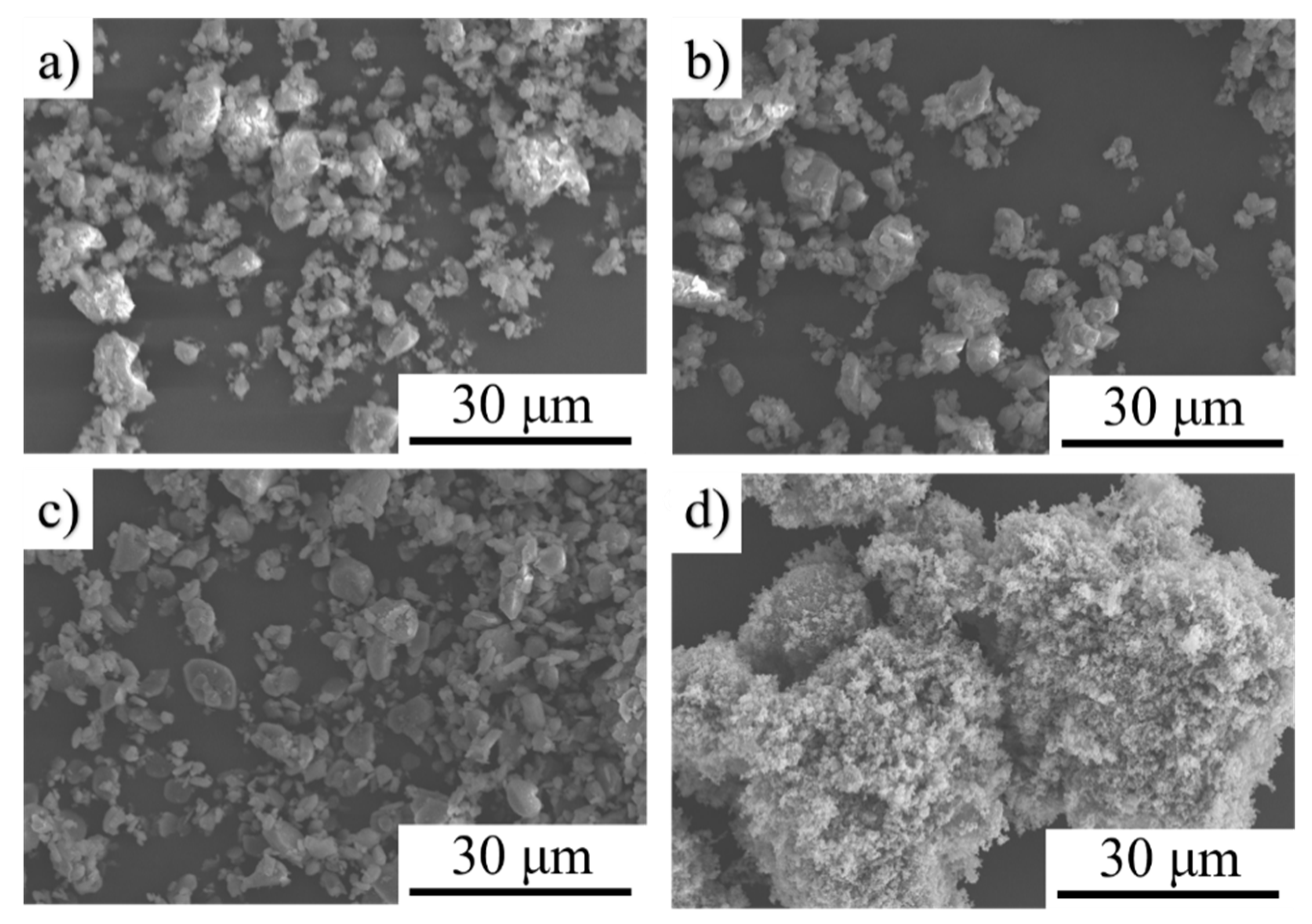
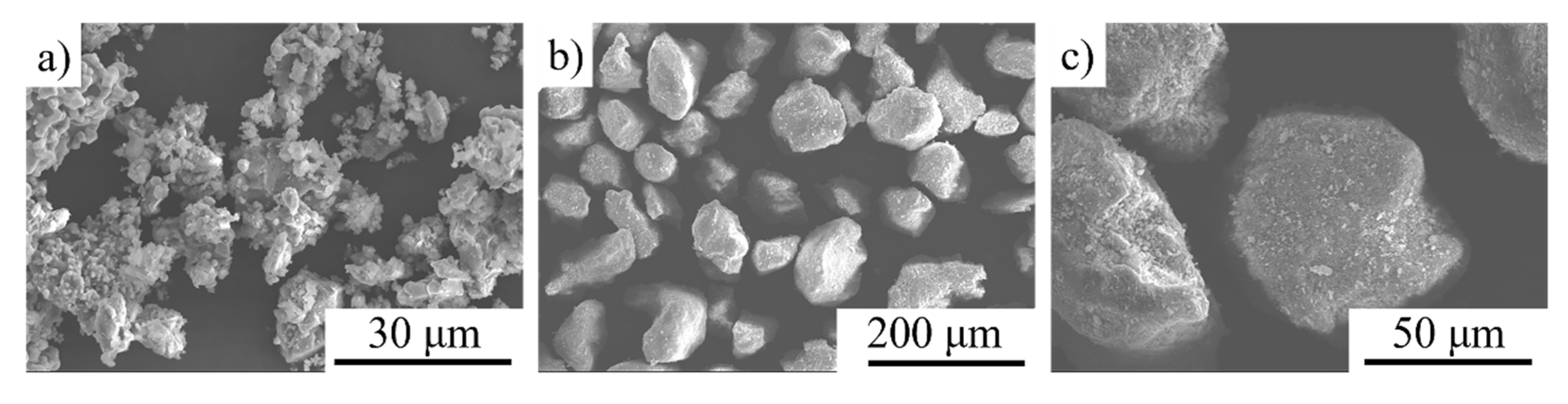
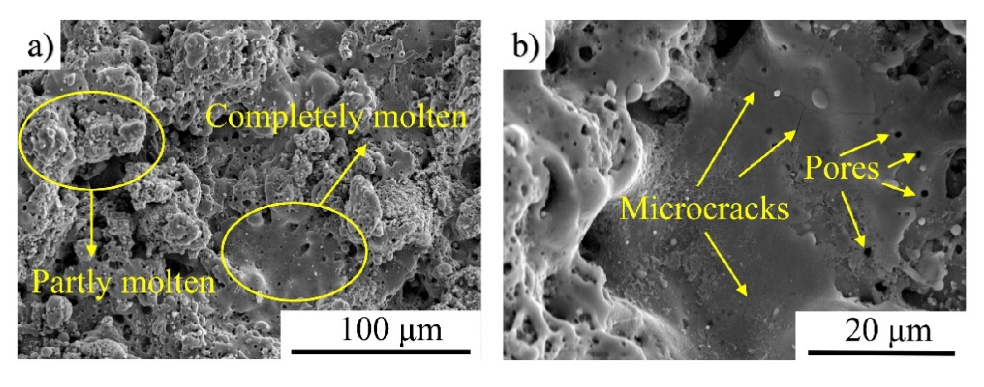
3.1. Microstructural Characterization of the Feed Powder and Coating

The morphology of the powder before and after granulation is shown in Figure 2. It can be seen that the blended powder before granulation has a size range of 3 to 30 µm and its shape is irregular (Figure 3a). After sieving, the granulated particles were polygonal with a very narrow size distribution from 30 to 75 µm (Figure 3b). This means that they had good flowability and could be delivered into the plasma in a controlled fusion. In addition, the granulated particles were dense agglomerates (Figure 3c), which ensured that the SiAlON particles inside could be heated less due to the protection of TiO2 in the spraying process.
The XRD patterns of the sintered SiAlON, feedstock powder and the coating are shown in Figure 4. Obviously, the phase of sintered SiAlON still included Si3N4, Al2O3 and AlN because the heat treatment did not make them react completely. TiO2 anatase and SiAlON are present in the initial powder. It is well known that plasma spraying is a non-equilibrium process, which is characterized by a high temperature, high velocity (>200 m/s) and extremely high cooling rate [24]. During the plasma spraying process, part of the TiO2 anatase underwent phase transformation to form TiO2 rutile, resulting in a decrease in its relative intensity. At the same time, the peak at 2θ = 33°, corresponding to the SiAlON phase, increased significantly. This is because the residual Si3N4, Al2O3 and AlN in the granulated particles transformed into SiAlON in the spraying process. SiAlON ceramics alone cannot be deposited as the coating when Z = 1 [19], so the presence of the SiAlON phase shows the protective effect of TiO2 particles during the deposition. In addition, SiO2 can be found in the coating, due to the oxidation of SiAlON and probably Si3N4 as well. The study has shown that the SiO2 formed during the spraying process facilitates the formation of the tribo-film, which is beneficial for the friction performance [25].
The surface morphology of the coating conveys information on the melting of particles. Figure 5 shows the surface morphologies of the as-sprayed coatings. The coating was composed of a typical microstructure characteristic of plasma sprayed coatings (Figure 5a). It can be observed from Figure 5b that the smelt particles flattened and some microcracks were formed due to the shrinkage of splats.
The experimental procedure is schematically shown Figure 6. The higher degree of melting enhances the inter-particle bonding with fewer pores in the coating but may lead to more decomposition of SiAlON (forming SiO2) since the absence of the protection of TiO2 means SiAlON is exposed to high-temperature plasma arcs; in contrast, the lower degree of melting reduces the inter-particle bonding with more pores in the coating but can result in less decomposition of SiAlON. The presence of TiO2 rutile indicates that the temperature of the outer layer of the composite powder reached the critical value of TiO2 phase transition during spraying, causing the phase transformation of TiO2 anatase, while the preservation of TiO2 anatase reflects that the temperature inside was lower than that of TiO2 phase transition. Note that the pores in the coating are considered beneficial since they allow oil retention for the boundary or starved lubrication conditions [26]. As the combined effects of inter-particle bonding, SiAlON content and porosity determine the wear resistance performance of the coating, the degree of particle melting should be well controlled. The cross-sectional images can provide more indication of the wear resistance properties of the coating.
Polished cross-sections were prepared to examine the internal microstructure of the as-sprayed coatings. In the cross-sections of the TiO2–SiAlON ceramic coatings, as shown in Figure 7a, there are no evident cracks at the interface junction between coating and substrate. Figure 7b shows that no penetrating crack is found in the as-sprayed coating, but some micro-voids were present, resulting from the insufficiently melted particles. The porosity of the as-sprayed coating is approximately 9%. In addition, energy dispersive X-ray spectroscopic (EDS) mapping of Al and Ti elements indicates that SiAlON ceramics and TiO2 were distributed homogenously in the coating (Figure 7c).

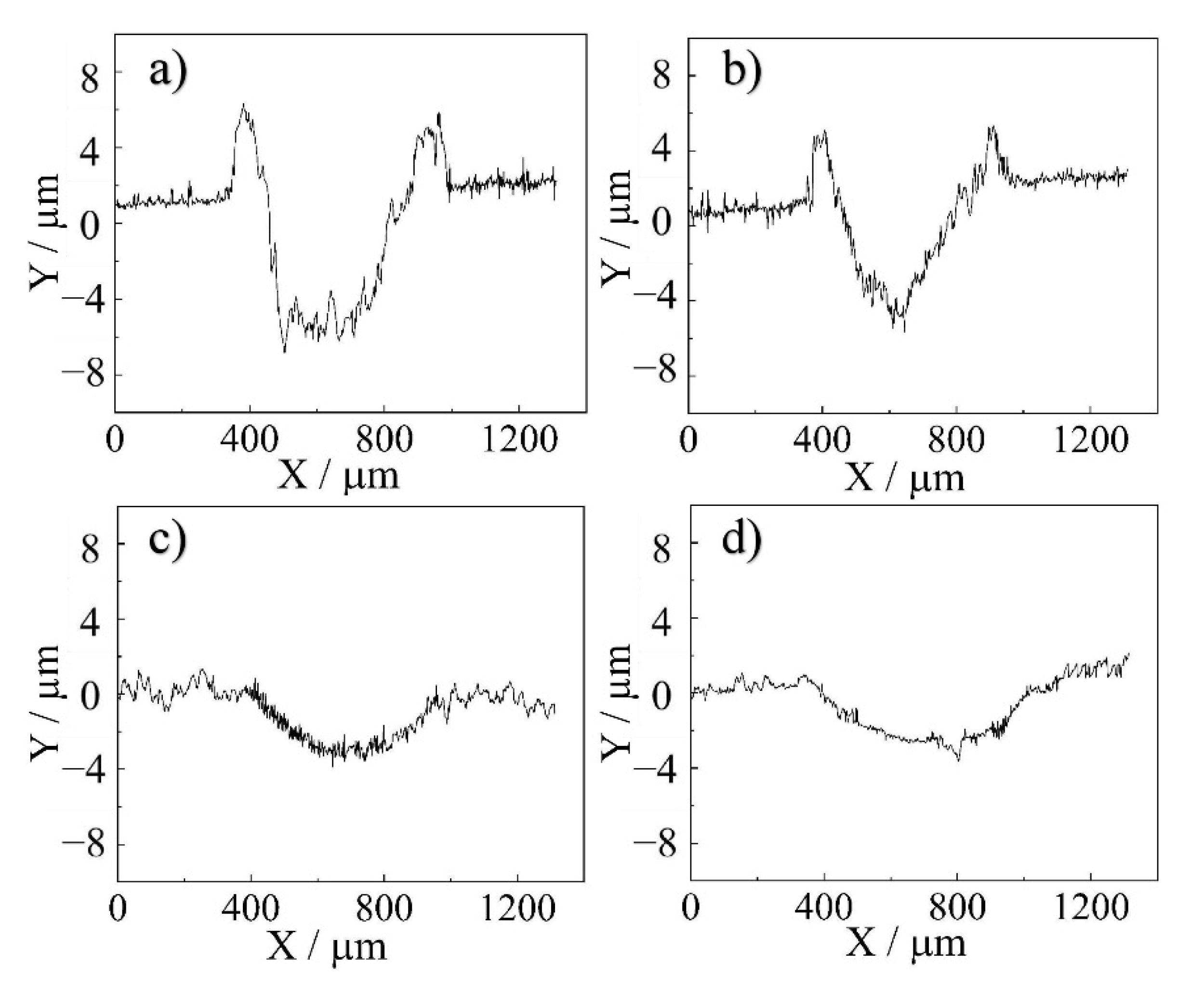
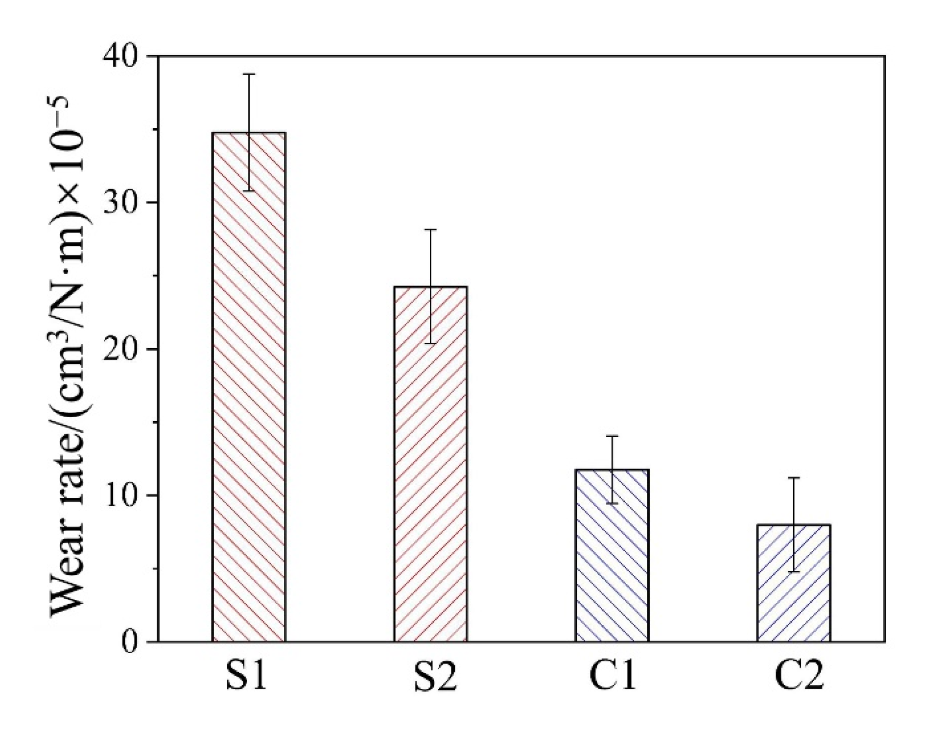
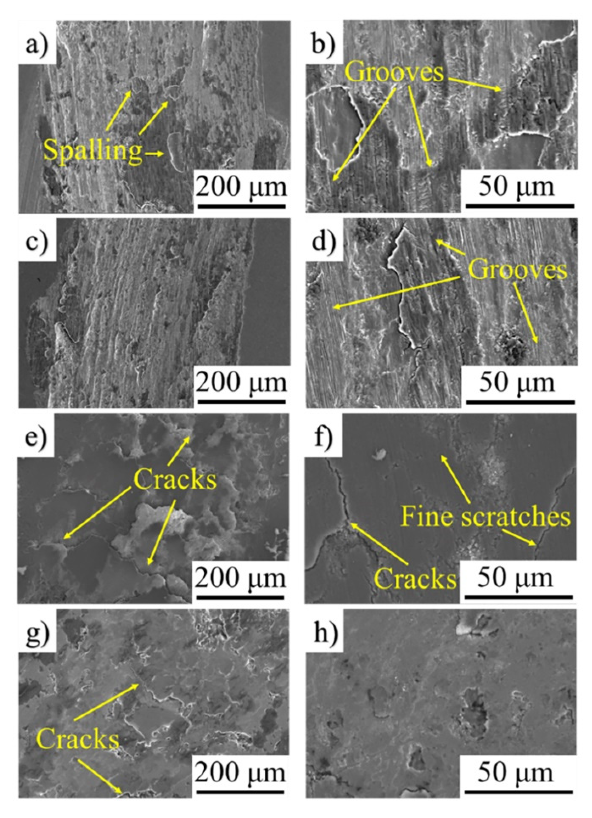
3.2. Adhesion Strength and Wear Behavior

The adhesion strength was tested on five samples, and the value was 24.3 ± 4.6 MPa, which is close to the reported values of pure TiO2 coatings [27,28]. This is because most TiO2 melts in the spray process, forming splats which then deform and interlock with the substrate.
The sliding wear characteristics of as-sprayed coatings against Si3N4 were evaluated with an applied load of 5 N and a speed of 0.1 m/s. Figure 8 depicts the friction coefficients of four samples. It shows that the friction coefficients of the coatings were smaller than those of the substrates in the final stabilized phase under both dry friction and starved lubrication conditions. The coefficients of friction (COF) of S1 and S2 have a similar tendency, but the friction coefficient of S2 is always smaller than that of S1 because of the lubricating oil. The friction coefficients of S1, S2 and C1 firstly increase, followed by a decrease and then gradually stabilize. Interestingly, the friction coefficient of C2 was very small and stable, fluctuating a little around 0.1. This is due to the oil film on the surface of the coating, as the pores of the coating become oil reservoirs. In other words, the wear was always well lubricated in the test.
Figure 9 shows 2D cross-sectional surface profile of the wear track of S1, S2, C1 and C2. It is worth mentioning that pile-up can be found at both sides of the worn surface of S1 and S2, indicating that plastic deformation took place during the wear test because of their lower microhardness [29], as well as dislocations in the lattice of the metal. From Figure 9a–d, we can get the information of both the width and depth of the wear track. Obviously, the depth of the track in the coatings is much smaller than that in the substrates. From the figure, the cross-sectional area of the wear and the wear rate can be calculated.
The wear rate was calculated using Equation (2) and is presented in Figure 10. As shown in the figure, the C2 coating possesses a wear rate (7.99 ± 3.21) × 10–5 cm3/N∙m, which is merely 23%, 33% and 68% of S1, S2 and C1, respectively. After having been immersed in the oil, the dense substrate forms a thin film of oil on the surface but acts as a lubricant only at the beginning of wear process. In contrast, the pores in the coating act as micro-reservoirs for oil, which can reduce the wear during the entire process. Therefore, the lubricated coating exhibits the best wear resistance compared with the others. Furthermore, as TiO2 rutile has a higher microhardness and better wear resistance when compared with the anatase phase [30,31], it is expected that blending TiO2 rutile with SiAlON as feed powder or conducting heat treatment will further improve the wear resistance of the coatings.
In order to reveal the failure process and wear mechanisms of the coatings, the worn surfaces of these samples were analyzed using SEM. Figure 11 shows the SEM images of the typical wear tracks of S1 and S2 substrates and C1 and C2 coatings at the normal load of 5 N. As shown in Figure 11a,b, many parallel grooves exist on the worn surface of the substrate, which indicate that the substrate suffered severe abrasion wear. In a tribological pair, where two surfaces with different materials are in direct contact and generate relative frictional motion, the harder material abrades and scratches the surface of the softer one [32]. Due to limited microhardness of the substrate, the abrasive wear can be the dominant mechanism. Additionally, the surface exhibits severe spalling signs. This indicates that under repeated shear stress, some splats tend to be detached, which is a feature of adhesion wear. From Figure 11c,d, it can be observed that the S2 sample exhibits severe wear similar to that of S1, with evident abrasive grooves. As seen in Figure 11e,f, the C1 sample shows much fewer abrasive grooves in its wear tracks. Moreover, the depth of the grooves is significantly reduced. This suggests that the coating could effectively protect the substrate from abrasion wear. Moreover, the tribolayer surface of TiO2–SiAlON is relatively flat and there are some brittle fracture traces and many fine scratches on the wear track. This means the ceramic coating undergoes surface fracture and slight abrasive wear. The coating under PAO (Figure 11g,h) exhibits a very smooth surface and has fewer cracks than the untreated coating.
The wear mechanisms are schematically demonstrated in Figure 12. Under the dry friction condition, wear debris are generated and accumulated on the wear track, leading to severe third-body abrasion during the friction and wear process under the micro-cutting effect of the asperities of the Si3N4 ball (Figure 12a). Figure 12b shows that under the starved lubrication condition, despite the existence of the oil layer as surface protection, the substrate still suffers from serious abrasive wear, which is only slightly less than that of dry friction. As shown in Figure 12c, the coating was cracked by the extrusion of the Si3N4 ball, which is different from the plastic deformation of the substrate. The pores on the surface of the coating become the origin of cracks in the wear test. Figure 12d shows that under the starved lubrication condition, fewer cracks form in the coating surface under the cover of the oil layer. The tiny pores in the coating can act as lubricant reservoirs that promote the retention of the fluid at the contact zone in the tests performed in PAO and form an oil layer [25]. The oil layer adsorbed on the surface of the friction pair can isolate the contact of the sliding ball and sample, which contributes to lower and more stable friction, resulting in lower wear rates.

4. Conclusions

In this study, TiO2–SiAlON ceramic coating was deposited on 316 stainless steel using plasma spraying. Comparative studies on the tribological behavior of the substrate and coating were performed. The main conclusions can be drawn as follows:
1.
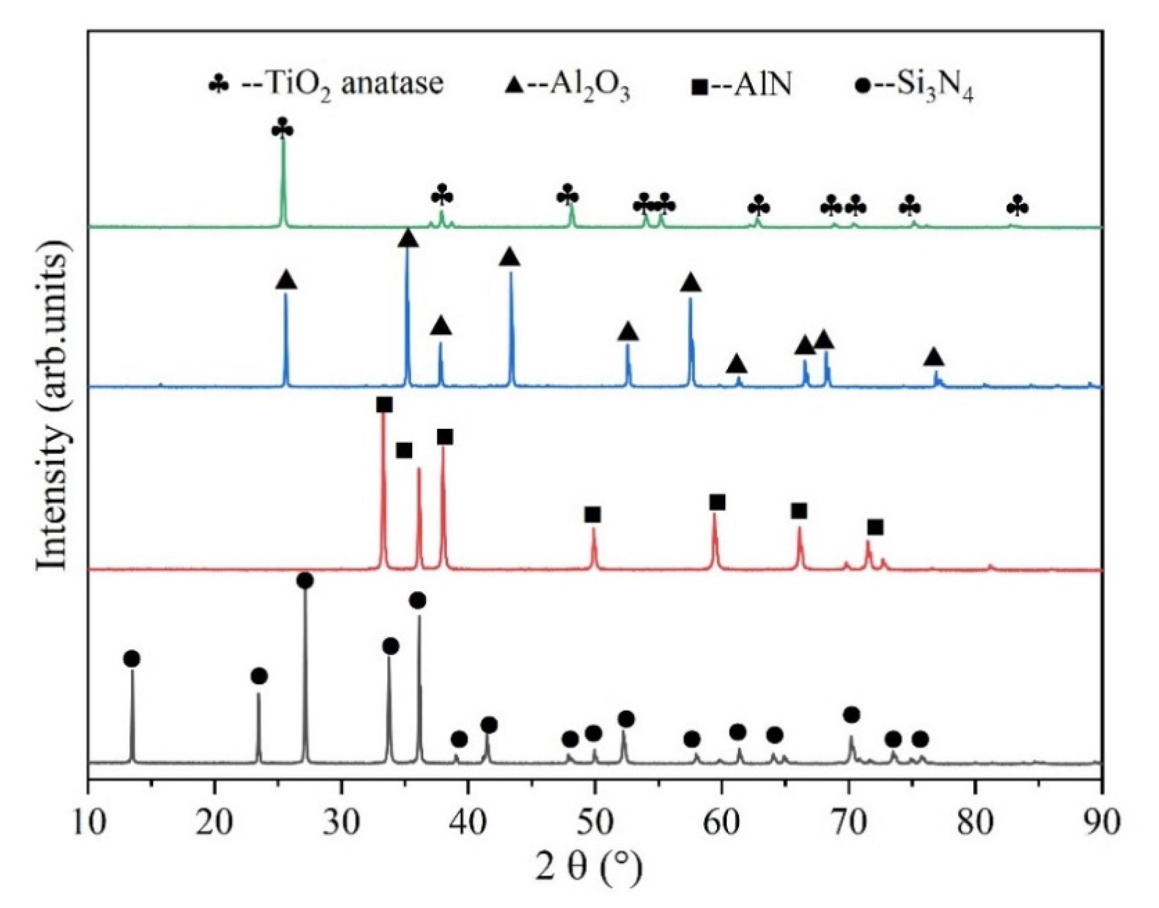
The sprayed TiO2–SiAlON coatings consisted of a SiAlON phase, TiO2 anatase phase and rutile phase. The residual Si3N4, Al2O3 and AlN in the granulated particles were transformed into SiAlON in the spraying process.
2.
The wear rate of the TiO2–SiAlON coating was merely 1/3 of that of the substrate under both dry and starved lubrication conditions. The ceramic coating also had a lower coefficient of friction than 316 stainless steel substrates.
3.
The wear mechanisms of the substrate were mainly severe abrasive wear and adhesive wear, accompanied by plastic deformation, while the surface fracture and slight abrasive wear were the wear mechanisms of the ceramic coating.

Author Contributions

Conceptualization: Y.W., W.W. and R.L.; formal analysis: J.M., L.T. and Y.W.; investigation: W.W.; data curation: Y.W. and W.W.; writing—original draft preparation: Y.W. and W.W.; writing—review and editing: Y.W., W.W. and R.L.; visualization: Y.W. and W.W.; supervision: R.L. All authors have read and agreed to the published version of the manuscript.

Funding

This study was supported by the National Natural Science Foundation of China (Grant No. 51575245) and the Senior Talent Foundation of Jiangsu University (No. 18JDG030).

Conflicts of Interest

The authors declare no conflict of interest.

References

  1. Ayas, E.; Kara, A. Novel electrically conductive α–β SiAlON/TiCN composites. J. Eur. Ceram. Soc. 2011, 31, 903–911. [Google Scholar] [CrossRef]
  2. Joshi, B.; Lee, H.H.; Wang, H.; Fu, Z.; Niihara, K.; Lee, S.W. The effect of different rare earth oxides on mechanical and optical properties of hot pressed α/β–Sialon ceramics. J. Eur. Ceram. Soc. 2012, 32, 3603–3610. [Google Scholar] [CrossRef]
  3. Khan, R.M.A.; Malki, M.M.A.; Hakeem, A.S.; Ehsan, M.A.; Laoui, T. Development of a single–phase Ca–α–SiAlON ceramic from nanosized precursors using spark plasma sintering. Mater. Sci. Eng. A 2016, 673, 243–249. [Google Scholar] [CrossRef]
  4. Smirnov, K.L. β–SiAlON–TiN/TiB2–BN composites by infiltration–mediated SHS under high pressure of nitrogen gas. Int. J. Self-Propag. High-Temp. Synth. 2016, 25, 80–85. [Google Scholar] [CrossRef]
  5. Çelik, A.; Lazoglu, I.; Kara, A.; Kara, F. Wear on SiAlON ceramic tools in drilling of aerospace grade CFRP composites. Wear 2015, 338, 11–21. [Google Scholar] [CrossRef]
  6. Letwaba, L.; Tlhabadira, I.; Daniyan, I.; Seerane, M.; Sadiku, E.; Masu, L. Development and microstructural analysis of beta–SiAlONs produced by spark plasma sintering. Mater. Today Proc. 2020. [Google Scholar] [CrossRef]
  7. Izhevskiy, V.A.; Genova, L.A.; Bressiani, J.C.; Aldinger, F. Progress in SiAlON ceramics. J. Eur. Ceram. Soc. 2000, 20, 2275–2295. [Google Scholar] [CrossRef]
  8. Yin, L.; Gao, W.; Jones, M.I. Wear behaviour and electrical conductivity of β–Sialon–ZrN composites fabricated by reaction bonding and gas pressure sintering process. Ceram. Int. 2019, 45, 2266–2274. [Google Scholar] [CrossRef]
  9. Yang, Z.; Shang, Q.; Shen, X.; Zhang, L.; Gao, J.; Wang, H. Effect of composition on phase assemblage, microstructure, mechanical and optical properties of Mg–doped SiAlON. J. Eur. Ceram. Soc. 2017, 37, 91–98. [Google Scholar] [CrossRef]
  10. Jones, M.I.; Hyuga, H.; Hirao, K.; Yamauchi, Y. Wear behaviour of single phase and composite sialon ceramics stabilized with Y2O3 and Lu2O3. J. Eur. Ceram. Soc. 2004, 24, 3271–3277. [Google Scholar] [CrossRef]
  11. Kumar, R.; Acikbas, N.C.; Kara, F.; Mandal, H.; Basu, B. Microstructure–Mechanical Properties–Wear Resistance Relationship of SiAlON. Ceram. Metall. Mater. Trans. A 2009, 40, 2319–2332. [Google Scholar] [CrossRef]
  12. Acikbas, N.C.; Kumar, R.; Kara, F.; Mandal, H.; Basu, B. Influence of β–Si3N4 particle size and heat treatment on microstructural evolution of α:β–SiAlON ceramics. J. Eur. Ceram. Soc. 2011, 31, 629–635. [Google Scholar] [CrossRef]
  13. Yi, X.; Niu, J.; Akiyama, T.; Harada, K.; Nakatsugawa, I. Spark Plasma Sintering Behavior of Combustion–Synthesized (Y, Ca)–α–SiAlON. Ceram. Int. 2016, 42, 15687–15693. [Google Scholar] [CrossRef]
  14. Qichun, S.; Zixi, W.; Jun, Y.; Yulin, L.; Jiongjie, L.; Zhuhui, Q.; Weimin, L. High–performance TiN reinforced Sialon matrix composites: A good combination of excellent toughness and tribological properties at a wide temperature range. Ceram. Int. 2018, 44, 17258–17265. [Google Scholar] [CrossRef]
  15. Sun, Q.; Yang, J.; Yin, B.; Cheng, J.; Zhu, S.; Wang, S.; Yu, Y.; Qiao, Z.; Liu, W. High toughness integrated with self–lubricity of Cu–doped SiAlON ceramics at elevated temperature. J. Eur. Ceram. Soc. 2018, 38, 2708–2715. [Google Scholar] [CrossRef]
  16. Sun, Q.; Yang, J.; Yin, B.; Tan, H.; Liu, Y.; Liu, J.; Cheng, J.; Qiao, Z.; Liu, W. Dry sliding wear behavior of β–SiAlON ceramics at wide range temperature from 25 to 800 °C. J. Eur. Ceram. Soc. 2017, 37, 4505–4513. [Google Scholar] [CrossRef]
  17. Qureshi, I.; Shahid, M.; Khan, A. Effect of bondcoat thickness on high temperature hot corrosion of ZrO2–8Y2O3 thermal barrier coating. Acta Phys. Pol. A 2015, 128, B314–B316. [Google Scholar] [CrossRef]
  18. Song, E.P.; Ahn, J.; Lee, S.; Kim, N.J. Microstructure and wear resistance of nanostructured Al2O3–8wt.% TiO2 coatings plasma–sprayed with nanopowders. Surf. Coat. Technol. 2006, 201, 1309–1315. [Google Scholar] [CrossRef]
  19. Sodeoka, S.; Ueno, K.; Hagiwara, Y.; Kose, S. Structure and properties of plasma–sprayed sialon coatings. J. Therm. Spray Technol. 1992, 1, 153–159. [Google Scholar] [CrossRef]
  20. Wang, X.; Feng, X.; Lu, C.; Yi, G.; Jia, J.; Li, H. Mechanical and tribological properties of plasma sprayed NiAl composite coatings with addition of nanostructured TiO2/Bi2O3. Surf. Coat. Technol. 2018. [Google Scholar] [CrossRef]
  21. Wang, J.Y.; Shan, Y.; Guo, H.; Wang, W.; Yi, G.; Jia, J. The Tribological Properties of NiCr–Al2O3–TiO2 Composites at Elevated Temperatures. Tribol. Lett. 2015, 58, 1. [Google Scholar] [CrossRef]
  22. ASTM C633-13. Standard Test Method for Adhesion or Cohesion Strength of Thermal Spray Coatings; ASTM International: West Conshohocken, PA, USA, 2017. [Google Scholar]
  23. Tian, L.H.; Xiong, W.; Liu, C.; Lu, S.; Fu, M. Microstructure and Wear Behavior of Atmospheric Plasma–Sprayed AlCoCrFeNiTi High–Entropy Alloy Coating. J. Mater. Eng. Perform. 2016, 25, 5513–5521. [Google Scholar] [CrossRef]
  24. Pawłowski, L. Strategic oxides for thermal spraying: Problems of availability and evolution of prices. Surf. Coat. Technol. 2013, 220, 14–19. [Google Scholar] [CrossRef]
  25. Mubarok, F.; Espallargas, N. Tribological Characterization of Thermally Sprayed Silicon Carbide Coatings. Tribol. Int. 2015, 85, 56–65. [Google Scholar] [CrossRef]
  26. Forn, A.; Picas, J.A.; Simón, M.J. Mechanical and tribological properties of Al–Si–Mo plasma–sprayed coatings. J. Mater. Process. Technol. 2003, 143, 52–57. [Google Scholar] [CrossRef]
  27. Zhao, X.; Liu, X.; Ding, C.; Chu, P.K. In vitro bioactivity of plasma–sprayed TiO2 coating after sodium hydroxide treatment. Surf. Coat. Technol. 2006, 200, 5487–5492. [Google Scholar] [CrossRef]
  28. Zhao, X.; Liu, X.; Ding, C.; Chu, P.K. Effects of plasma treatment on bioactivity of TiO2 coatings. Surf. Coat. Technol. 2007, 201, 6878–6881. [Google Scholar] [CrossRef]
  29. Su, Y.; Zhang, Y.; Song, J.; Hu, L. Tribological behavior and lubrication mechanism of self–lubricating ceramic/metal composites: The effect of matrix type on the friction and wear properties. Wear 2017, 372, 130–138. [Google Scholar] [CrossRef]
  30. Kaczmarek, D.; Domaradzki, J.; Wojcieszak, D.; Prociow, E.; Mazur, M.; Placido, F.; Lapp, S. Hardness of Nanocrystalline TiO2 Thin Films. J. Nano Res. 2012, 18, 195–200. [Google Scholar] [CrossRef]
  31. Bertrand, G.; Berger–Keller, N.; Meunier, C.; Coddet, C. Evaluation of metastable phase and microhardness on plasma sprayed titania coatings. Surf. Coat. Technol. 2006, 200, 5013–5019. [Google Scholar] [CrossRef]
  32. Hashemi, S.; Parvin, N.; Valefi, Z. Effect of microstructure and mechanical properties on wear behavior of plasma–sprayed Cr2O3–YSZ–SiC coatings. Ceram. Int. 2019, 45, 5284–5296. [Google Scholar] [CrossRef]
Figure 1. SEM micrographs of as-received powders: (a) Si3N4, (b) AlN, (c) Al2O3, (d) TiO2.
Coatings 10 01268 g001
Figure 2. XRD patterns of as-received powders.
Coatings 10 01268 g002
Figure 3. SEM micrographs of feed powder: (a) before granulation; (b,c) after granulation.
Coatings 10 01268 g003
Figure 4. XRD patterns of sintered SiAlON, feed powder and coating.
Coatings 10 01268 g004
Figure 5. The surface micrographs of the coating: (a) low magnification; (b) high magnification.
Coatings 10 01268 g005
Figure 6. The schematic diagram of the spray coating design of TiO2–SiAlON.
Coatings 10 01268 g006
Figure 7. The cross-sectional micrographs and Al and Ti elemental EDS maps of the coating: (a) the microstructure of the interface, (bd) micrograph and corresponding EDS map of the coating.
Coatings 10 01268 g007
Figure 8. The COF of coatings and substrates.
Coatings 10 01268 g008
Figure 9. 2D cross-sectional surface profile of the wear track: (a) S1, (b) S2, (c) C1, (d) C2.
Coatings 10 01268 g009
Figure 10. The wear rate of S1, S2, C1 and C2.
Coatings 10 01268 g010
Figure 11. The SEM images of the wear tracks: (a,b) S1, (c,d) S2, (e,f) C1, (g,h) C2.
Coatings 10 01268 g011
Figure 12. Schematic drawings of wear mechanisms and system details in ball on disc wear test of substrate and coating under both dry and starved lubrication conditions with poly-alpha-olefin (PAO) as lubricant: (a) S1, (b) S2, (c) C1, (d) C2.
Coatings 10 01268 g012
Table 1. Principal parameters used during plasma spraying.
ParameterValues
Current, A800
Voltage, V56
Primary gas flow rate (argon), L/min55
Secondary gas flow rate (nitrogen), L/min20
Carrier gas flow rate (argon), L/min7
Rotating speed of powder feeder, g/min20
Spraying distance, mm70
Table 2. The names of samples under different test conditions.
Test conditionSubstrateCoating
Dry frictionS1C1
Starved lubricationS2C2
Publisher’s Note: MDPI stays neutral with regard to jurisdictional claims in published maps and institutional affiliations.

