Article

Evolution of the Microstructure and Properties of Pre-Boronized Coatings During Pack-Cementation Chromizing

1
College of Material Science and Engineering, Chongqing University of Technology, Chongqing 400054, China
2
Chongqing Municipal Key Laboratory of Institutions of Higher Education for Mould Technology, Chongqing 400054, China
3
School of Materials and Energy, Southwest University, Chongqing 400715, China
*
Authors to whom correspondence should be addressed.
Coatings 2020, 10(2), 159; https://doi.org/10.3390/coatings10020159
Submission received: 6 January 2020 / Revised: 29 January 2020 / Accepted: 8 February 2020 / Published: 9 February 2020
(This article belongs to the Section Corrosion, Wear and Erosion)

Abstract

:
The effect of chromizing time on the microstructure and properties of B–Cr duplex-alloyed coating prepared by a two-step pack-cementation process was investigated. The phases, microstructure, and element distribution of three coatings obtained were characterized by X-ray diffraction (XRD), secondary electron imaging (SEI), backscattering electron imaging (BSEI), and energy dispersive spectroscopy (EDS), respectively. The results show that as the chromizing time increases, the net-like Fe2B and rod-like CrFeB phases in the coating gradually disappear, and finally completely transform into the block-like Cr2B and CrxCy (Cr7C3 and Cr23C6) phases. The growth kinetics analysis shows that interface reaction dominates the coating growth during the early stage of chromizing, while atomic diffusion gradually controls the coating growth at the later stage. The evolution mechanism of the B-Cr duplex-alloyed coating was also discussed.

1. Introduction

Surface coating techniques (such as hard coatings and solid lubricating coatings prepared by thermo-diffusion, spraying, plating, etc.) are the main means used to improve the surface properties of materials [1,2,3,4,5,6,7]. Thermo-diffusion coating treatments, such as carbonizing, nitriding, boronizing, and chromizing, are effective techniques for the protection of metal materials from wear and/or corrosion [8,9,10,11,12]. However, single thermo-diffusion coatings usually only improve a certain property of the parts, and can’t meet the demands of some mechanical parts (gears, shafts, etc.) working in severe environments, which are characterized by high-speed, cyclic heavy-load, and/or corrosiveness [11,13]. For example, the wear resistance of boronized sample (hardness higher than 1600 HV) can be strengthened greatly [14,15], but the corrosion resistance is still poor and is also accompanied by brittleness [14].
For chromized samples, studies have pointed out that there is a carbon-poor layer (hardness lower than the substrate) existing between the Cr coating and steel substrate [11,13,16,17]. Fortunately, it has been reported that these shortcomings can be avoided by duplex coating or composite coating treatments [18,19,20,21,22]. Yilbas et al. [23] developed a dual-layer coating on carbon steel, which consisted of a top layer that provided wear resistance and a bottom layer that provided corrosion resistance. Likewise, previous works have proved that the boron-chromium duplex coating (B-Cr coating) has excellent comprehensive properties, such as high hardness, good wear resistance, and corrosion resistance [24,25]. In addition, the brittleness of boronizing can also be modified by the B-Cr coating treatment [14,25]. Therefore, the B-Cr coating has great application prospects in the field of surface protection of metal materials. Pack-cementation is a frequently-used method to prepare thermo-diffusion coatings [26,27,28,29,30,31,32,33] and metallurgical bonding can be produced between the coatings and the substrate materials by this method [34]. For the B-Cr duplex coatings prepared by pack-cementation, depending on different treatment orders, three kinds of processes can be chosen: simultaneous boronizing and chromizing (SBCr), chromizing followed by boronizing (CrB), and boronizing followed by chromizing (BCr) [24,25,35]. In the early studies, the SBCr treatment was rarely reported. The main reason for this is that the B atoms and Cr atoms react with each other and then chromium borides are formed in the pack powders instead on the steel surface, which causes a huge difficulty on the coating growth. For the CrB and BCr-coatings, it has been reported that the BCr-coating is thicker than the CrB coating, and the BCr-coating possesses more excellent properties [25]. Additionally, Fe-Cr solid solution, chromium carbides (Cr23C6, Cr7C3 and CrC, etc.) or alloyed cementite ((Cr,Fe)7C3 and (Cr,Fe)23C6) can be formed on the carbon steels after the chromizing treatment [36,37,38,39]. Thereby, the surface layer of the steels becomes more compact due to the entry of large-sized Cr atoms and the formation of chromium compounds.
In our previous study, it has been found that the B–Cr duplex-alloyed coating with excellent properties can be obtained through a two-step pack-cementation process of pre-boronization and subsequent chromization [14]. Moreover, there is no carbon-poor zone in the substrate in the BCr sample [14]. In the present work, the influences of chromizing time on the microstructure and properties of the BCr-coating were investigated. The microstructure evolution and growth kinetics of the BCr-coatings were studied and analyzed.

2. Experimental Details

2.1. Sample Preparation

AISI 5140 carbon steel with a nominal composition of 0.40%C, 0.80%Cr, 0.27%Mn, 0.23%Si, 0.03%Ni, and Fe-balance (in wt.%, and hereafter) was selected as the raw material. Prior to coating treatment, the raw material was quenched (austenitizing at 860 °C for 1h, and then water quenching) and tempered (580 °C for 1 h), and then cut into cube samples with the dimension of 25 × 20 × 6 mm3. Finally, mechanically polishing and ultrasonic cleaning are performed.
A two-step pack-cementation process consisting of pre-boronization (PB) and subsequent chromization was used to prepare the B-Cr coating. The composition of the PB powder was: 50% ferroboron (containing 20% B and 80% Fe) as feedstock, 40% Al2O3 as the inert filler, 5% KBF4 as the activator, and 5% La2O3 as the modifier, while the composition of the chromizing powder was: 45% pure Cr as feedstock, 45% Al2O3 as the inert filler, 5% NH4Cl as the activator, and 5% La2O3 as the modifier. All powders were less than 75 μm in diameter. In order to mix the powders thoroughly, all powders were mixed in a blender for 60 min. The PB treatment was performed in a box-type heating furnace at 950 °C for 3 h. Then, the PB samples were chromized in an induction heating furnace at 1000 °C. Three chromizing times of 15, 30, and 60 min were used. The samples were denoted as BCr-15, BCr-30 and BCr-60, respectively. Readers may refer to [14] for details of the pack-cementation process.

2.2. Characterization and Properties Test

Phase identification of various samples was conducted using an X-ray diffraction instrument (XRD, Empyrean Series 2, PANalytical, Almelo, The Netherlands) with Cu Kα radiation, an angle range of 20° to 90°, and a step size of 0.013°. Microstructure and morphologies were detected from the cross-sectional views of the samples by using secondary electron imaging (SEI) and backscattering electron imaging (BSEI) detectors installed in a field emission gun scanning electron microscope (FEGSEM, Zeiss Sigma HD, Zeiss, Dresden, Germany). The distribution of elements (Fe, Cr, C, and B) in the three kinds of coatings was assessed by an energy-dispersive spectroscopy (EDS, AZtech Max2, Oxford Instruments, London, UK) installed on the FEGSEM. Prior to characterizations, the mechanical polishing and subsequently electropolishing treatments were carried out on the cross-sections of coated samples. And the latter was conducted in an electrolyte of 10 vol.% perchloric acid and 90 vol.% ethanol at about −30 °C for 60 s, with a voltage of 30 Volt and a current of 0.4 Amp.
Microhardness from surface to substrate was measured on a Vickers indenter (HVS-1000Z, Shanghai CSOIF Co. Ltd., Shanghai, China), with a load of 2 N and a dwell time of 10 s. Wear resistance was tested on a reciprocating tribometer (HSR-2M, Zhongke Kaihua Technology Development, Lanzhou, China). The friction pairs were AISI 52100 steel balls (chemical composition Fe-1.0C-1.5Cr-0.30Mn-0.25Si-0.1Mo, in wt.%, and hardness 720~760 HV) with the diameter of 6 mm. The load was 15 N and the duration time was 30 min.

3. Results and Discussion

3.1. Phase Evolution

The X-ray diffraction spectra of various samples are presented in Figure 1. The International Diffraction Data Center (ICDD) database was used to determine all the different phases. The results show that the as-tempered material has a ferrite phase, while the main phase is changed to Fe2B after pre-boronizing. After different time chromizing, the primary phase of the coatings varies again. The ferrite and M2B-type borides (Fe2B, Cr2B and CrFeB) are observed in the BCr-15 sample, while the coating of the BCr-30 sample is composed of ferrite, M2B-type borides (Fe2B, Cr2B and CrFeB) and chromium carbide Cr7C3. Pure Cr, chromium boride Cr2B, τ-phase Fe23(C, B)6 and chromium carbides CrxCy (Cr7C3 and Cr23C6) are observed in the BCr-60 sample. As the chromizing time increases, the content of chromium compounds (including Cr2B, CrxCy) increases significantly, while the content of Fe2B decreases noticeably. This indicates that the chromizing time has a significant effect on the diffusion degree and chemical reaction of the Fe, Cr, C and B elements.

3.2. Microstructure Evolution

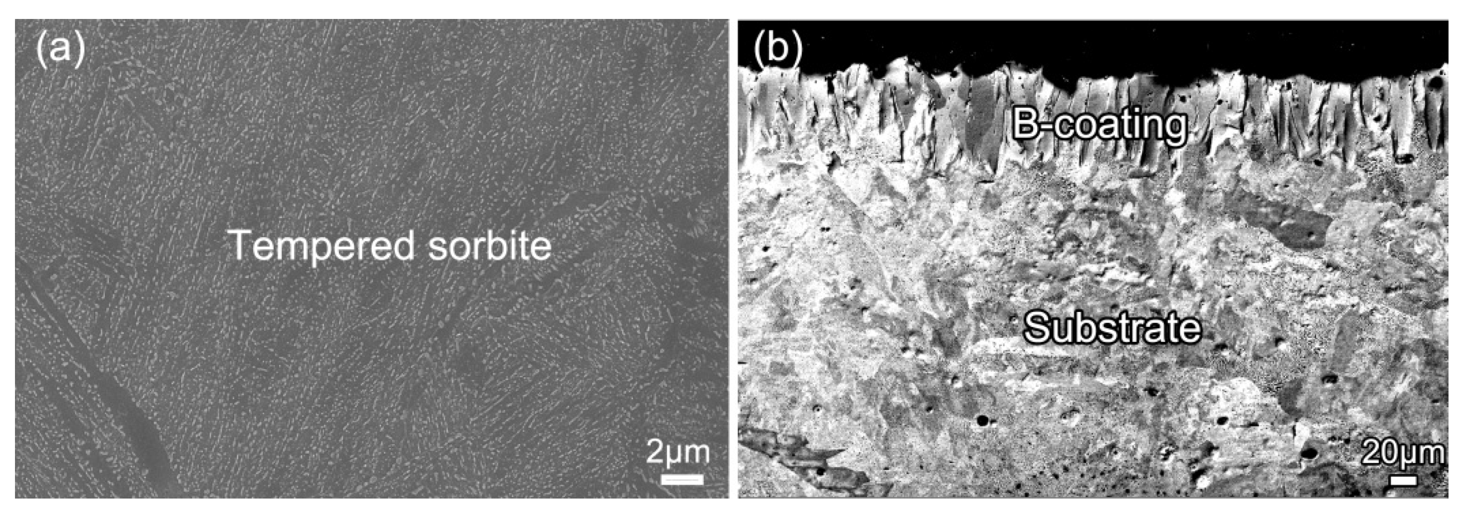
Figure 2a shows the microstructure of the as-tempered material. As can be seen, nano-sized sphere-shaped or rod-shaped carbides are homogeneously distributed in the grained ferrite phase, indicating a typical tempered sorbite morphology [40]. The cementite particles are too fine to be detected by the XRD. After pre-boronizing treatment, a typical saw-toothed B-coating consisting of columnar grains with the length direction perpendicular to the coating surface can be clearly observed, as shown in Figure 2b. According to the XRD analysis, the columnar grains are mainly composed of Fe2B phase. It should be noted that the brittle FeB phase may also be formed during pre-boronizing treatment, which leads the degradation of coating properties [41]. FeB is mainly generated in the outermost layer of the coating [14] and has been ground away before the XRD test in this study. The average thickness of the B-coating is about 70 μm. Additionally, the temperature of boronizing is higher than that of austenitizing, hence the substrate changes from the tempered sorbite into the mixed microstructure of ferrite and pearlite, exhibiting a hypoeutectoid steel morphology [42].
The microstructure and element distribution of the BCr-15 sample are presented in Figure 3. After chromizing, the coating morphology is remarkably different from that of the PB sample. The original B-coating consisting of columnar Fe2B grains changes to a coating composed of a great number of equiaxed grains and second-phase particles (see Figure 3a,b). From Figure 3d, it can be seen that the Cr element has penetrated into the original B-coating, but the content of Cr in the coating is lower than that of Fe. According to previous studies [14], the equiaxed grains are determined as the pearlite with high content of Cr element (HC-pearlite, hereafter). The second-phase particles mainly present three morphologies: net-like, rod-like, and block-like, as shown in Figure 3b, c. It has been reported that with the addition of Cr element in the Fe-B alloy, the continuously distributed net-like eutectic Fe2B structure is scattered, changing into dispersed M2B-type boride structures (mainly containing (Fe,Cr)2B, CrFeB or Cr2B) [43]. The XRD patterns also confirm the presence of Fe2B, CrFeB, and Cr2B phases in the BCr-15 sample (see Figure 1). Thus, it can be confirmed that the net-like phase is Fe2B, the rod-like and block-like structures are composed of CrFeB and Cr2B phases (see Figure 3c). Such hard borides have been widely reported in the literature [24,44,45].
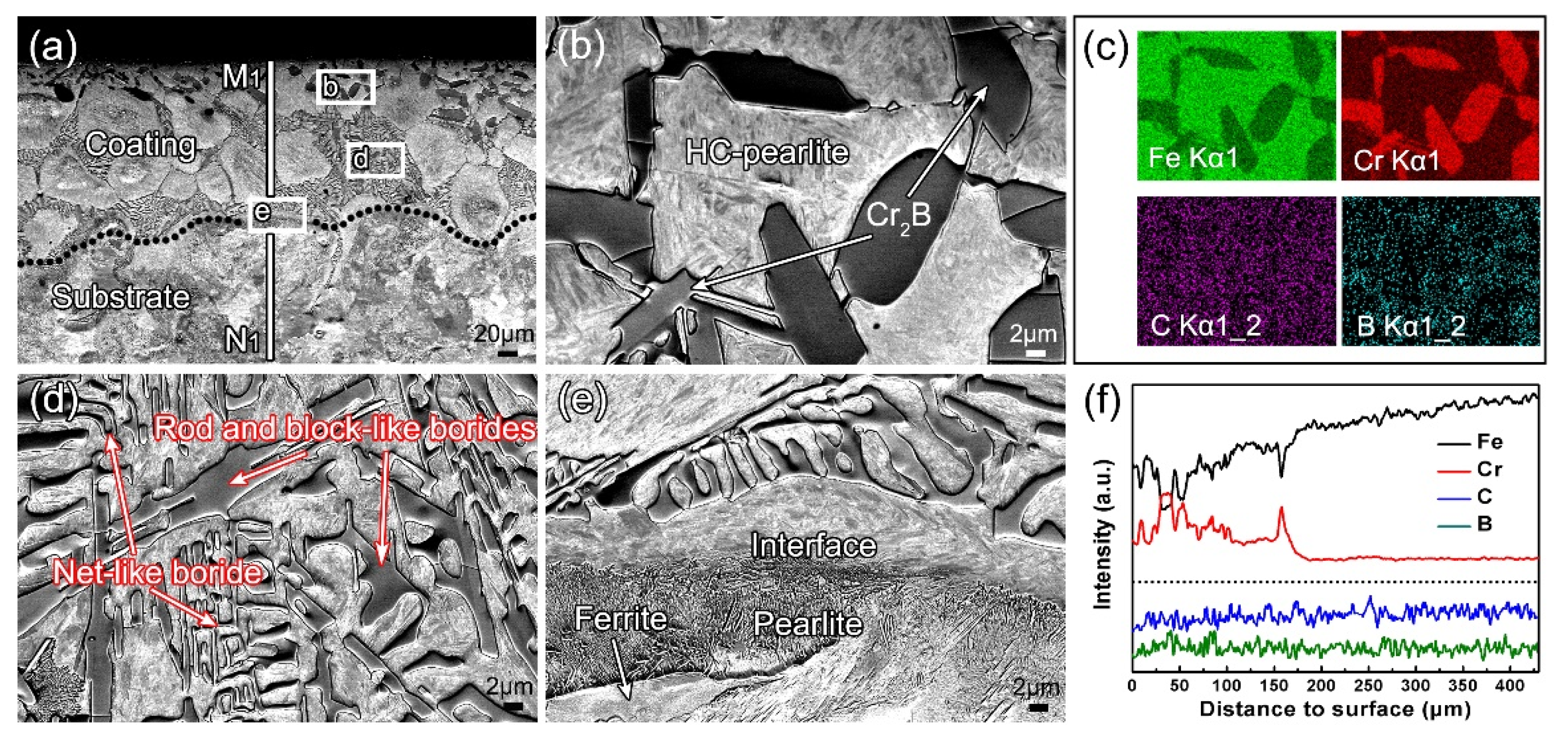
Figure 4 shows the microstructure and EDS results of the BCr-30 sample. Both HC-pearlite and the second-phase particles also can be observed in the coating of the BCr-30 sample. Unlike BCr-15 sample, only dark block-like particles can be clearly distinguished from the HC-pearlite (see Figure 4a) in the upper-layer of the coating (near the surface). From Figure 4b, it can be seen that the size of the block-like particles is much larger than that in the BCr-15 sample, and such large particles are mainly distributed at the grain boundaries. The EDS results (see Figure 4c,f) show that the dark block-like particles are rich in Cr and B, corresponding to the Cr2B phase in the XRD pattern (Figure 1). It has been reported that Cr-rich particles tend to precipitate at the grain boundaries during thermal-chromizing at high-temperature [46]. However, the C element is also enriched in the block-like particles (see Figure 4c), so the Cr2(B,C) (the structure of Cr2(B,C)is similar to that of Cr2B, the XRD doesn’t detect such a phase) may be contained. As shown in Figure 4d, like BCr-15 sample, the net-like, rod-like and block-like borides can be distinguished in the inner-layer of the coating (near the substrate). As the chromizing time increases from 15 to 30 min, the content of Cr2B increases greatly especially in the upper-layer of the coating. At the same time, the substrate morphology does not change significantly and still shows a typical equilibrium structure of the hypoeutectoid steel, as shown in Figure 4e.
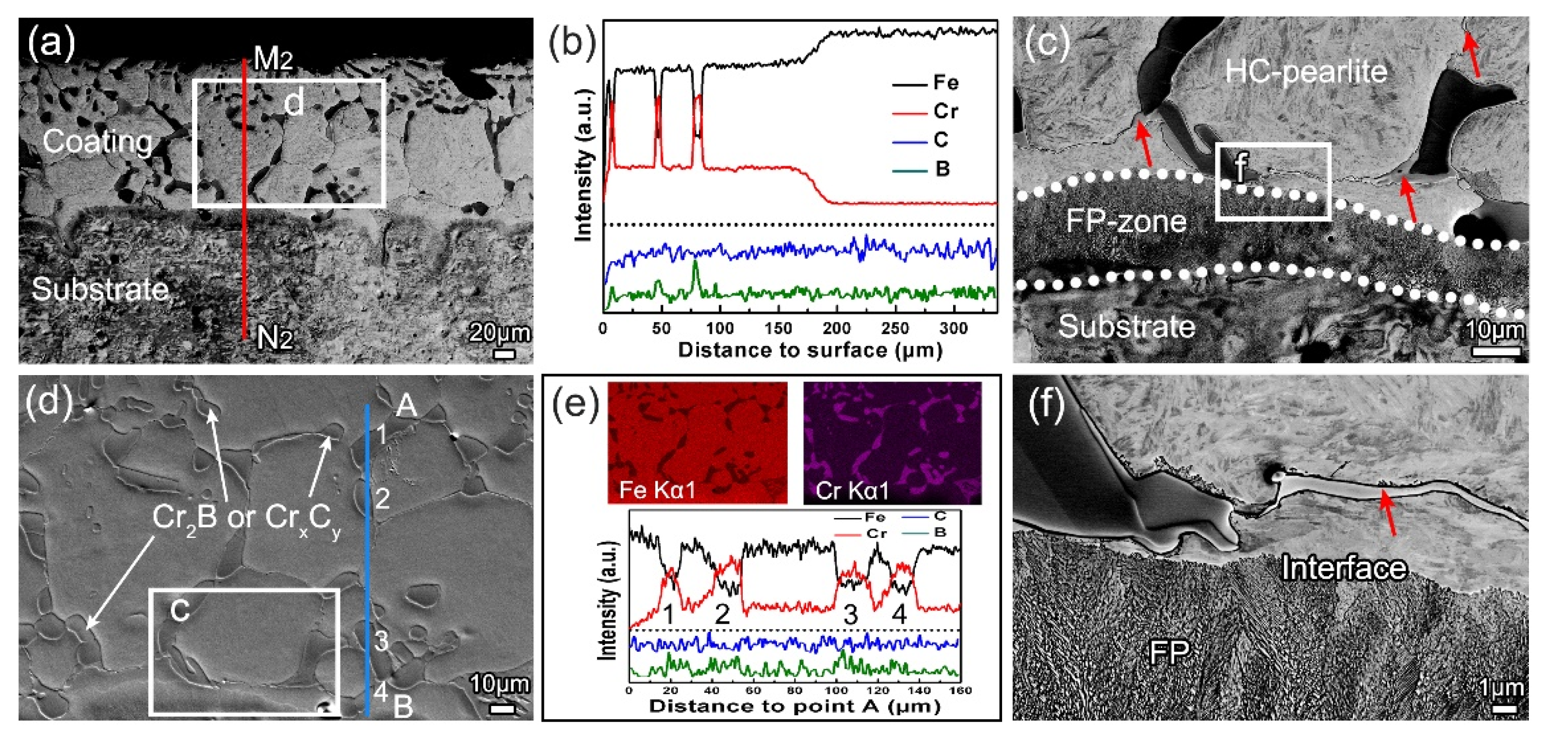
Figure 5 presents the microstructure and EDS results of the BCr-60 sample. From Figure 5a, it can be seen that the coating is also composed of HC-pearlite and second-phase particles. However, only block-like particles are observed in the entire coating. Moreover, such block-like particles are mainly distributed at the grain boundaries (see Figure 5d). According to the EDS results (see Figure 5b,e) and XRD patterns (see Figure 1), it can be inferred that the block-like structure consists of Cr2B and CrxCy (Cr7C3 and Cr23C6). This result is consistent with our previous study [14]. That is, as the chromizing time further increases, the net-like and rod-like borides gradually disappear, and only the block-like phase (Cr2B and CrxCy) is retained. In addition, some band-like particles (marked by red arrows in Figure 5c,f) are distributed at the phase boundaries of Cr2B (or CrxCy) and the grain boundaries of HC-pearlite. Such band-like particles are determined as τ-phase Fe23(C,B)6 according to the XRD analysis and the literature [14,47]. A fine pearlite zone (FP-zone) can also be observed at the interface between the coating and substrate, as shown in Figure 5c,f. It indicates that some Cr atoms have diffused into the substrate. It is because that the formation of FP-zone is resulted from the refinement of the pearlite structure by the Cr element in solid solution of the steel matrix [11]. It can be summarized that as the chromizing time increases, the net-like and rod-like borides distributed on the HC-pearlite grains disappear, and completely change into the block-like structures of Cr2B and CrxCy which mainly distribute at the grains or phase boundaries.

3.3. Growth Kinetics and Evolution Mechanism Analysis

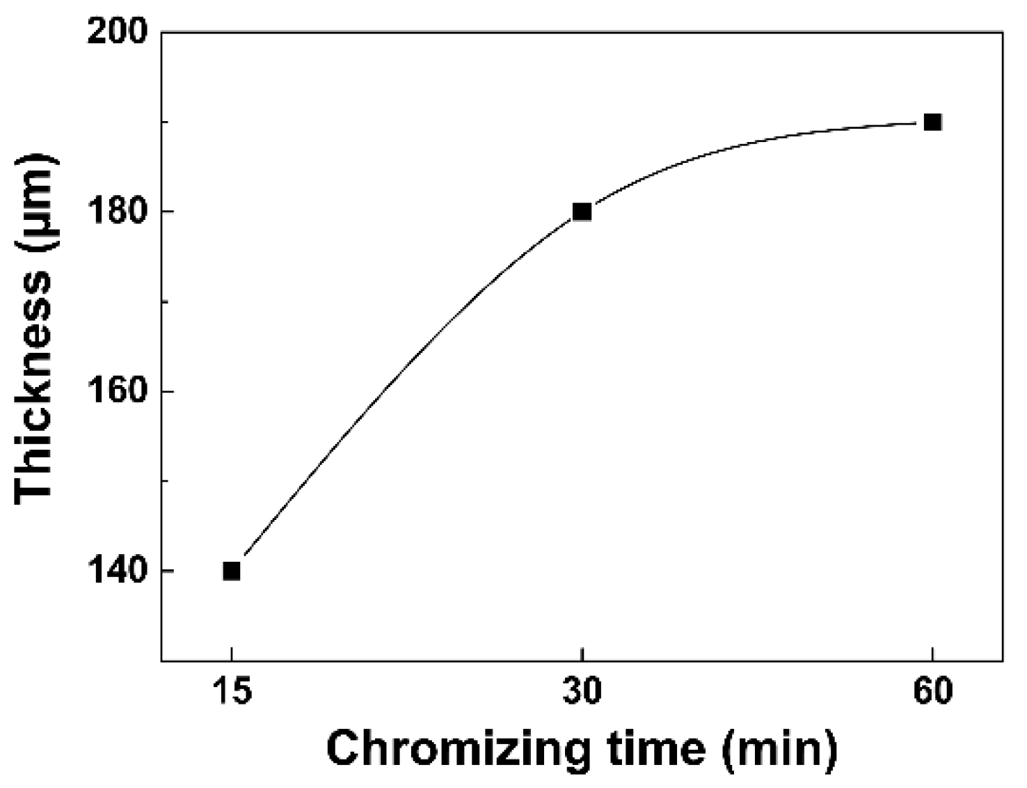
The thickness of the three coatings was measured, as shown in Figure 6. As the chromizing time increases from 15 to 30 min, the coating thickness increases from 140 to 180 μm. When the chromizing time increases from 30 to 60 min, the coating thickness only increases by about 10 μm (180 μm to 190 μm). That is, as the chromizing time increases, the growth and development of the coating become slower. This result is consistent with the literature report, that is, thicker the layer, the lower the interphase velocity [41]. It can be attributed to the increase in the diffusion resistance of Cr atoms as the coating thickness increases.
In the past studies, many researchers have investigated the kinetics of diffusion controlled process during coating treatments [48,49,50], but the interface reaction at early stage of coating treatment was not taken into account. Ghadi et al. [51] have declared that the growth process of coatings consists of interface (or interface reaction) controlled growth and subsequently diffusion controlled growth. Figure 7 displays the two kinds of growth modes: interface controlled growth at early stage, and diffusion controlled growth at late stage. It is well-known that Cr is a strong carbide forming element, which is able to easily react with C element at the high-temperature [11]. Moreover, the enthalpy of boride formation for Fe (Fe2B = –28 kJ mol−1·atom−1) is lower than Cr (Cr2B = –35 kJ mol−1·atom−1), indicating that Cr has a stronger propensity to react with B to form boride than Fe [52]. The rapid growth of the BCr-coating at early stage is mainly attributed to the interface chemical reactions, as show in Figure 7a. At late stage, a large number of chromium carbides and chromium borides are formed at the interface, and the degree of chemical reaction is reduced. Thus, the coating growth mainly depends on the diffusion of various atoms (Figure 7b). At this stage, the growth rate of the coating will inevitably decrease.
Generally, the growth of coatings follows Equation (1):
d n = K t
where d is the thickness of coatings, K is the constant coefficient, t is the treating time, and n reveals the coating growth modes. According to [51], when n is near 2, the growth mode is diffusion controlled growth. When n is near 1, the growth mode is interface controlled growth. In this study, the early stage growth follows Equation (2):
d 1 = K i t
and the late stage growth follows Equation (3):
d 2 2 = K d t
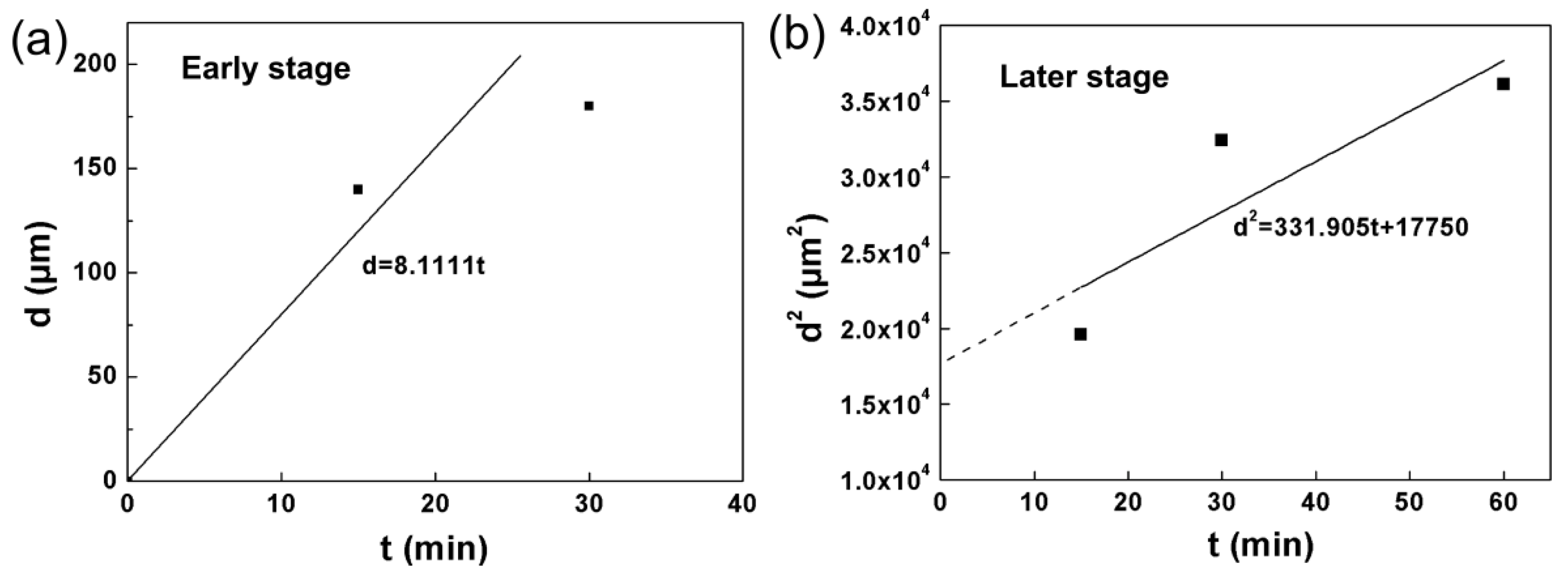
In Equations (2) and (3), d1 and d2 is the coating thickness of different stages, Ki is the interface reaction coefficient, Kd is the diffusion coefficient. According to the two equations, the curves illustrating the relationship between d and t can be fitted, as presented in Figure 8.
Figure 8a indicates that the thickness of Cr-diffusion coating is proportional to chromizing time at early stage (about the first 30 min). It can also be recognized that the square of coating thickness changes linearly with chromizing time at late stage (after about 30 min) (see Figure 8b). That is to say, a parabolic relation between the thickness and treating time is determined at late stage, also as shown in Figure 6. The fitted equations in Figure 8 can be employed to roughly predict the thickness of BCr-coating treated at 1000 °C under different chromizing time.
In addition, it is well-known that the growth of coatings is closely related to the chemical potential of various elements. At the early stage of pack chromizing, according to the elemental concentration gradient, it can be inferred that the lower Cr potential (LCrP) is existed in the pre-boronized sample, and the lower B and C potential (LBCP) is existed in the chromizing powders (see Figure 7a). Hence, the atom diffusion (Cr from the powders to the sample, B and C from the sample subsurface to the surface) is accelerated. However, at late stage, the diffusion rate is vastly limited, due to the increasing Cr potential (ICrP) and the increasing B and C potential (IBCP) in the corresponding area (see Figure 7b) caused by the continuous reaction and diffusion. Thus, it can be concluded that the interface reaction controlled growth and lower chemical potential lead to the rapid growth of the BCr-coating at early stage, but the diffusion controlled growth and increasing chemical potential result in the decrease of growth rate at late stage.
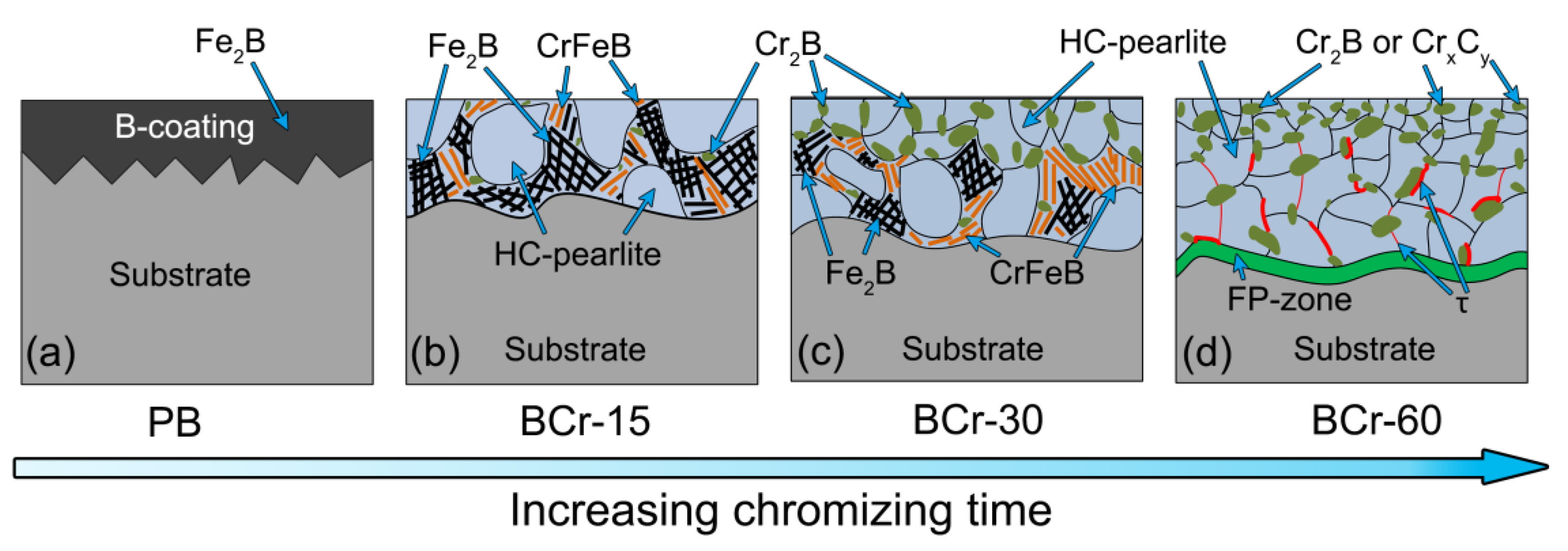
Figure 9 shows sketch maps of the microstructure evolution during pack-chromization. The schematic microstructure of the pre-boronized sample is depicted in Figure 9a. Previous investigations have discovered that the efficiency of induction-heating is much higher than that of traditional resistance furnace heating, and the diffusion rate of each atom is larger as well [10,11,14]. It is known that Fe2B begins to decompose at about 900 ~ 1000 °C during the heating process [47], and then the B atoms start to diffuse into the Cr-layer and substrate. For the BCr-15 sample, the concentration of B atoms will decrease during chromizing due to the diffusion of B atoms. Therefore, the dense Fe2B having a columnar grain structure mainly becomes the continuously distributed net-like structures after cooling to room temperature (see Figure 9b). At the same time, Cr atoms originating from the packed powders also diffuse into the coating. Some Cr atoms are dissolved into the iron lattices, while some react with the B atoms to form the M2B-type borides (Cr2B and CrFeB). When the chromizing time further increases, more and more Cr atoms diffuse into the B-coating. Due to the high concentration of Cr atoms in the outer layer of the coating, a great number of block-like Cr-rich structures (Cr2B) are formed in the upper layer of the coating (see Figure 9c). In addition, the number of rod-like phase also increases. However, the continuously distributed Fe2B structures are obviously scattered, and gradually tend to disappear (see Figure 9c). From Figure 9d, it can be seen that most of the second-phase particles present block-like structure, and the rest present band-like after chromizing for 60 min. This is because that a large fraction of B atoms react with the Cr atoms to form the Cr2B phase as a result of the further increase of Cr concentration. Meanwhile, the C atoms also move from the substrate to the coating, owing to the low carbon potential in the coating caused by the addition of carbide forming element Cr [13]. Consequently, the block-like chromium carbides CrxCy (Cr7C3 and Cr23C6) are formed. It should be noted that the Cr has a larger interstitial lattice site and a lower atomic packing factor, so the solid solubility of B and C atoms in Cr is much higher than that in Fe [11]. This is a dominant reason for the formation of Cr2B and CrxCy. The formation of τ-phase (band-like structure) has been researched in other studies [14,47]. Moreover, the presence of fine pearlite zone (FP-zone) is also attributed to the Cr addition [11,53].

3.4. Performance Comparison

3.4.1. Microhardness

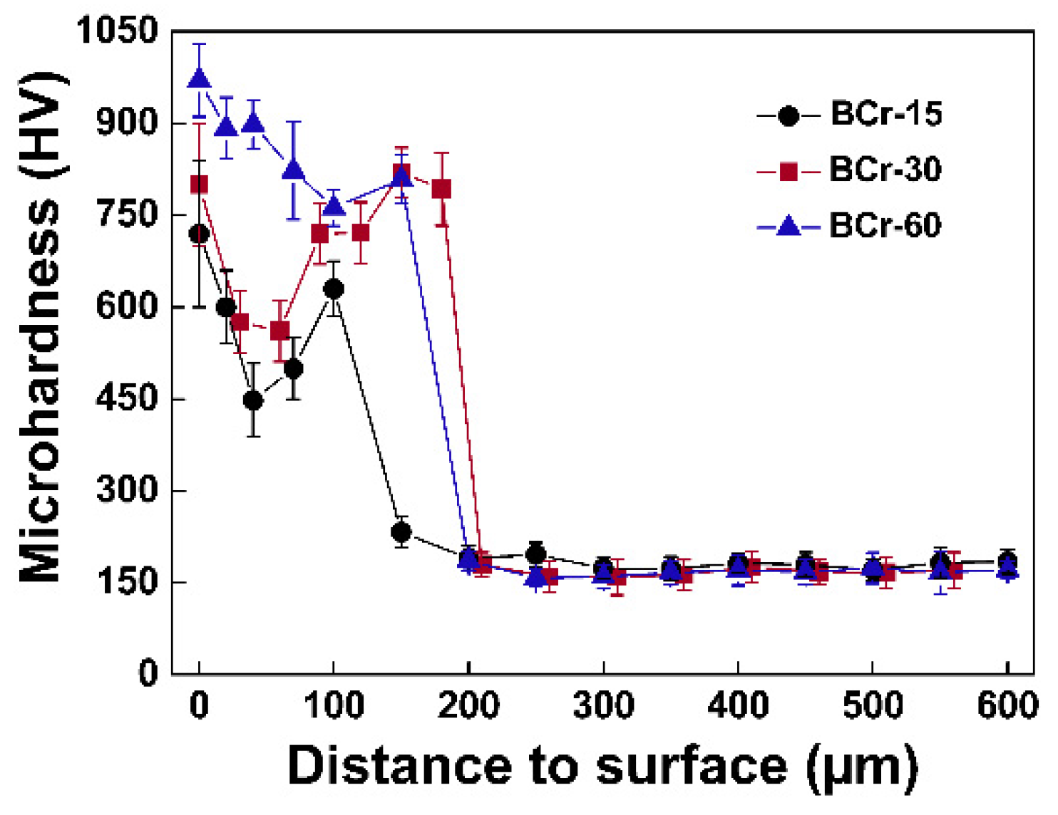
Figure 10 exhibits the sectional microhardness curves of various samples. It can be seen that the hardness of the coatings is far higher than that of the steel substrate. The hardness of pure oriented Fe2B crystals with high brittleness reaches up to 1760~1880 HV [54]. Generally, the microhardness of the boronized coating is about 1600 HV [14,47], which is higher than that of Cr2B, CrxCy, and HC-pearlite. The microhardness of reticular Fe2B is considered to be lower than that of Fe2B with a compact columnar grain structure, resulting in that the microhardness of the duplex-alloyed coatings is lower than that of the single boronized coating. Overall, the average hardness of the coating increases remarkably with increasing chromizing time. This is attributed to the continuous diffusion of Cr atoms from powders to the coating [55]. Aghaie-Khafri et al. [24] also have proved that the microhardness of B-Cr duplex coating increases with increasing heating time. Moreover, all the three samples have the peak hardness on the coating surface, measured as about 720, 800, and 970 HV, respectively. But the difference is that in the coating, as the distance from the surface increases, the hardness of the BCr-60 sample decreases linearly, while the BCr-15 and BCr-30 samples decrease first and then increase. The results show that as the chromizing time increases, the net-like Fe2B and rod-like CrFeB phases gradually disappear, and finally completely transform into the block-like Cr2B and CrxCy (Cr7C3 and Cr23C6) phases in the coating. This is because that with the increase of chromizing time, the net-like Fe2B and rod-shaped CrFeB phases with lower hardness are gradually replaced by the block-like Cr2B and CrxCy with higher hardness. This difference in hardness distribution also proves that the phase and structure of the coating vary as the chromizing time increases.

3.4.2. Friction-Related Wear Behavior

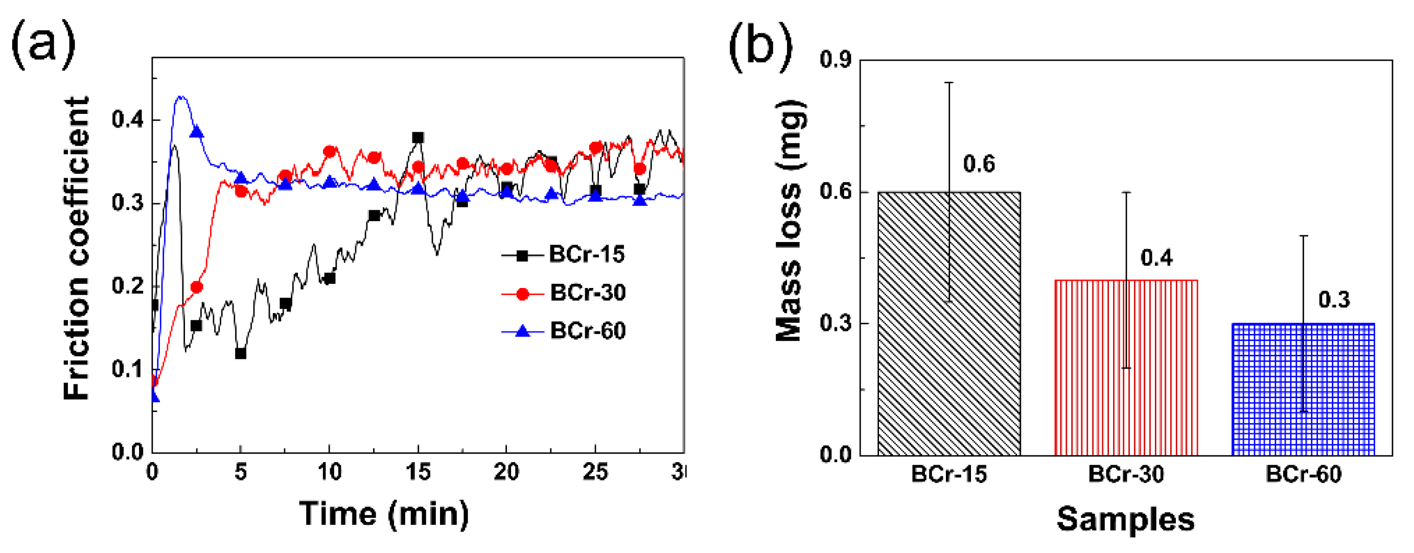
Figure 11 presents the wear morphologies of various samples (wear tests of as-tempered and pre-boronized samples were conducted in [14]). The widths of the wear scars are measured as 621, 642 and 584 μm, respectively. Figure 12a displays the friction coefficient plotted as a function of sliding friction time of the three samples. The friction coefficient is considered to be an important parameter for evaluating friction and wear performance of materials. Studies have shown that in most cases the wear resistance can be improved as the friction coefficient decreases [16,22]. In the first 15 min of the wear test, the friction coefficient of various samples will fluctuate greatly. This is mainly related to the surface roughness of different coatings. As the wear time increases, the friction coefficient tends to stabilize. This is because that the area in contact with the friction pair becomes smoother. Here, the friction coefficient around the 30th minute is stable and measured as about 0.35, 0.35 and 0.30, respectively. That is, as the chromizing time increases, the wear resistance is enhanced.
The mass loss of the three samples is shown in Figure 12b. Obviously, the mass loss of the BCr-15 and BCr-30 samples is larger than that of the BCr-60 sample, due to the lower surface hardness (see Figure 10) and surface exfoliation (white arrows in Figure 11a,b). This further confirms that the BCr-60 coating has a better friction-related wear resistance.
It should be noted that some surface defects (such as micro-cracks, pits and voids, etc.) that are unavoidably introduced during the preparation of the coatings by the pack-cementation technique will negatively affect the surface roughness and application properties of the coatings, such as wear and corrosion resistance. Lower coating roughness, with a Ra value below 2 μm, is beneficial for performance [56]. Therefore, how to reduce or eliminate surface defects will become one of the problems that researchers need to solve. Scientists have paid attention to the effects of surface defects on PVD (physical vapour deposition) and CVD (chemical vapour deposition) coatings and how to eliminate them. For instance, Rodríguez-Barrero et al. have pointed out that drag grinding/ polishing could be regarded as a suitable post-treatment process for optimizing coating final roughness and improving performance of the hard nanostructured coatings prepared by PVD [57]. Hu et al. [16] have suggested that high-temperature annealing can reduce and even eliminate micro-cracks of the coatings fabricated by electro brush-plating. The control of surface defects of the pack-cementation coatings also should be taken more seriously in the future research.

4. Conclusions

In this study, a B-Cr duplex-alloyed coating was prepared on AISI 5140 steel by a two-step pack-cementation process of pre-boronization and subsequent chromization. The effects of chromization time on the structure and properties of the pre-boronization layer were studied. The main conclusions can be drawn as follows:
  • As the chromizing time increases, the phases of the B-Cr duplex-alloyed coating vary significantly. The BCr-15 coating is composed of ferrite and borides (Fe2B, Cr2B, and CrFeB), while the BCr-30 coating contains ferrite, borides (Fe2B, Cr2B, and CrFeB), and a small amount of chromium carbide Cr7C3. Pure Cr, chromium boride Cr2B, τ-phase Fe23(C,B)6, and chromium carbides CrxCy (Cr7C3 and Cr23C6) are detected in the BCr-60 sample.
  • In terms of microstructure, the B-Cr duplex-alloyed coatings mainly contain equiaxed grains of HC-pearlite and different second phases. As the chromizing time increases, the second phases change from the net-like Fe2B to the block-like Cr2B and CrxCy.
  • Kinetics analysis reveals that the interface reaction leads to the rapid growth of the BCr coating at the early stage, and the diffusion controlled growth results in the slow growth at the late stage of chromizing.
  • With the prolonging of chromizing time, the average microhardness of the coatings exhibits an increasing trend, and the wear resistance is significantly improved.

Author Contributions

Conceptualization, J.H.; methodology, J.Z.; software, N.G.; validation, X.Y. and J.H.; formal analysis, H.L., J.H. and N.G.; investigation, J.H. and N.G.; resources, J.H.; data curation, J.H. and N.G.; writing—original draft preparation, J.H., J.Z. and N.G.; writing—review and editing, N.G.; supervision, H.X.; project administration, J.H. and H.X.; funding acquisition, J.H. and N.G. All authors have read and agreed to the published version of the manuscript.

Funding

This work was co-supported by the Natural Science Foundation of China (51575073), Fundamental Research Funds for the Central Universities of China (No. XDJK2019B066), Scientific and Technological Research Program of Chongqing (cstc2017jcyjBX0031), Scientific and Technological Research Program of Banan District of Chongqing (2018TJ06), the Graduate scientific research innovation project of Chongqing (CYS18308) and Program for Innovation Team Building at Institutions of Higher Education in Chongqing (CXTDG20162017).

Conflicts of Interest

The authors declare that they have no conflict of interest.

References

  1. Zong, L.; Guo, N.; Li, R.; Yu, H. Effect of B content on microstructure and wear resistance of Fe-3Ti-4C hardfacing alloys produced by plasma-transferred arc welding. Coatings 2019, 9, 265. [Google Scholar] [CrossRef]
  2. Hu, J.; He, C.; Yang, X.; Li, H.; Xu, H.; Guo, N. Microstructure and tribological properties of self-lubricating FeS coating prepared by chemical bath deposition coating technique. Appl. Sci. 2019, 9, 4422. [Google Scholar] [CrossRef]
  3. Dehghanghadikolaei, A.; Fotovvati, B. Coating techniques for functional enhancement of metal implants for bone replacement: A review. Materials 2019, 12, 1795. [Google Scholar] [CrossRef]
  4. Beck-Broichsitter, M. Polymer-coated aperture plates for tailored atomization processes. Mater. Sci. Eng.: C. 2020, 110, 110666. [Google Scholar] [CrossRef]
  5. Fu, J.; Ma, S.; Zhu, X.; Xu, C.; Yan, Z.; Cheng, D.; Ma, C. Influence of solid lubricant WS2 on the tribological properties of plasma electrolytic oxidation coating of ZL109. Mater. Res. Express 2019, 6, 1265c8. [Google Scholar]
  6. Nicoll, A.R.; Gruner, H.; Prince, R.; Wuest, G. Thermal spray coatings for high temperature protection. Surf. Eng. 1985, 1, 59–71. [Google Scholar] [CrossRef]
  7. Ravi, K.; Deplancke, T.; Lame, O.; Ogawa, K.; Cavaillé, J.-Y.; Dalmas, F. Influence of nanoceramic interlayer on polymer consolidation during cold-spray coating formation. J. Mater. Process Tech. 2019, 273, 116254. [Google Scholar] [CrossRef]
  8. Dai, J.; Guan, H.; Chai, L.; Xiang, K.; Zhu, Y.; Qiu, R.; Guo, N.; Liu, Y. Comparative study of microstructural characteristics and hardness of β-quenched Zr702 and Zr–2.5Nb alloys. Materials 2019, 12, 3752. [Google Scholar] [CrossRef]
  9. Anees, S.M.; Dasari, A. A review on the environmental durability of intumescent coatings for steels. J. Mater. Sci. 2017, 53, 124–145. [Google Scholar] [CrossRef]
  10. Hu, J.; Zhang, Y.; Yang, X.; Li, H.; Xu, H.; Ma, C.; Dong, Q.; Guo, N.; Yao, Z. Effect of pack-chromizing temperature on microstructure and performance of AISI 5140 steel with Cr-coatings. Surf. Coat. Technol. 2018, 344, 656–663. [Google Scholar] [CrossRef]
  11. Hu, J.; Ma, C.; Yang, X.; Xu, H.; Guo, N.; Yu, H. Microstructure evolution during continuous cooling in AISI 5140 steel processed by induction heating chromizing. J. Mater. Eng. Perform. 2017, 26, 5530–5537. [Google Scholar] [CrossRef]
  12. Jiang, J.; Hu, J.; Yang, X.; Guo, N.; Xu, H.; Li, H.; Jin, Y.; Yu, H. Microstructure and annealing behavior of Cr-coatings deposited by double glow plasma on AISI 5140 steel. Results Phys. 2019, 15, 102674. [Google Scholar] [CrossRef]
  13. Hu, J.; Wang, J.; Jiang, J.; Yang, X.; Xu, H.; Li, H.; Guo, N. Effect of heating treatment on the microstructure and properties of Cr–Mo duplex-alloyed coating prepared by double glow plasma surface alloying. Coatings 2019, 9, 336. [Google Scholar] [CrossRef]
  14. Hu, J.; Zeng, J.; Yang, Y.; Yang, X.; Li, H.; Guo, N. Microstructures and wear resistance of boron-chromium duplex-alloyed coatings prepared by a two-step pack cementation process. Coatings 2019, 9, 529. [Google Scholar] [CrossRef]
  15. Lindner, T.; Löbel, M.; Sattler, B.; Lampke, T. Surface hardening of FCC phase high-entropy alloy system by powder-pack boriding. Surf. Coat. Technol. 2019, 371, 389–394. [Google Scholar] [CrossRef]
  16. Hu, J.; Jiang, J.; Li, H.; Yang, X.; Xu, H.; Jin, Y.; Ma, C.; Dong, Q.; Guo, N. Effect of annealing treatment on microstructure and properties of Cr-coatings deposited on AISI 5140 steel by brush-plating. Coatings 2018, 8, 193. [Google Scholar] [CrossRef]
  17. Hosmani, S.S.; Kuppusami, P.; Goyal, R.K. Chromizing, Carburizing, and Duplex Surface Treatment. In An Introduction to Surface Alloying of Metals; Springer: New Delhi, India, 2014; pp. 89–101. [Google Scholar]
  18. Lin, C.-K.; Hsu, C.-H.; Cheng, Y.-H.; Ou, K.-L.; Lee, S.-L. A study on the corrosion and erosion behavior of electroless nickel and TiAlN/ZrN duplex coatings on ductile iron. Appl. Surf. Sci. 2015, 324, 13–19. [Google Scholar] [CrossRef]
  19. Luo, X.; Wang, Y.Q.; Yang, Y.Q.; Zhang, M.X.; Huang, B.; Liu, S.; Jin, N. Effect of C/Mo duplex coating on the interface and tensile strength of SiCf/Ti-21Al-29Nb composites. J. Alloys Compd. 2017, 721, 653–660. [Google Scholar] [CrossRef]
  20. Rahmani, S.; Omrani, A.; Shabanpanah, S. Structure, surface properties and corrosion resistance of St 37 steel coated with PS/Ni-Ba-B duplex coatings. Surf. Coat. Technol. 2019, 373, 1–6. [Google Scholar] [CrossRef]
  21. Hu, J.; Ma, C.; Xu, H.; Guo, N.; Hou, T. Development of a Composite Technique for Preconditioning of 41Cr4 Steel Used as Gear Material: Examination of Its Microstructural Characteristics and Properties. Sci. Technol. Nucl. Install. 2016, 2016, 1–6. [Google Scholar] [CrossRef]
  22. Zhang, F.; Yan, M. Microstructure and wear resistance of in situ formed duplex coating fabricated by plasma nitriding Ti Coated 2024 Al Alloy. J. Mater. Sci. Technol. 2014, 30, 1278–1283. [Google Scholar] [CrossRef]
  23. Yilbas, B.S.; Kumar, A.; Bhushan, B. Single- and two-layer coatings of metal blends onto carbon steel: Mechanical, wear, and friction characterizations. JOM 2013, 66, 37–45. [Google Scholar] [CrossRef]
  24. Aghaie-Khafri, M.; Mohamadpour Nazar Abady, M. A study of chromo-boronizing on DIN 1.2714 steel by duplex surface treatment. JOM 2012, 64, 694–701. [Google Scholar] [CrossRef]
  25. Kheyrodin, M.; Habibolahzadeh, A.; Mousavi, S.Y.B. Wear and corrosion behaviors of duplex surface treated 316L austenitic stainless steel via combination of boriding and chromizing. Prot. Met. Phys. Chem. Surf. 2017, 53, 105–111. [Google Scholar] [CrossRef]
  26. Günen, A.; Kanca, E.; Çakir, H.; Karakaş, M.S.; Gök, M.S.; Küçük, Y.; Demir, M. Effect of borotitanizing on microstructure and wear behavior of Inconel 625. Surf. Coat. Technol. 2017, 311, 374–382. [Google Scholar] [CrossRef]
  27. Pourasad, J.; Ehsani, N.; Valefi, Z. Oxidation resistance of a SiC–ZrB2 coating prepared by a novel pack cementation on SiC-coated graphite. J. Mater. Sci. 2016, 52, 1639–1646. [Google Scholar] [CrossRef]
  28. Balusamy, T.; Sankara Narayanan, T.S.N.; Ravichandran, K. Effect of surface mechanical attrition treatment (SMAT) on boronizing of EN8 steel. Surf. Coat. Technol. 2012, 213, 221–228. [Google Scholar] [CrossRef]
  29. Lin, N.; Guo, J.; Xie, F.; Zou, J.; Tian, W.; Yao, X.; Zhang, H.; Tang, B. Comparison of surface fractal dimensions of chromizing coating and P110 steel for corrosion resistance estimation. Appl. Surf. Sci. 2014, 311, 330–338. [Google Scholar] [CrossRef]
  30. Xie, F.; Zhang, G.; Pan, J. Characterizing AISI 1045 steel surface duplex-treated by alternating current field enhanced pack aluminizing and nitriding. Appl. Surf. Sci. 2018, 431, 44–47. [Google Scholar] [CrossRef]
  31. Campos-Silva, I.; Ortiz-Domínguez, M.; Bravo-Bárcenas, O.; Doñu-Ruiz, M.A.; Bravo-Bárcenas, D.; Tapia-Quintero, C.; Jiménez-Reyes, M.Y. Formation and kinetics of FeB/Fe2B layers and diffusion zone at the surface of AISI 316 borided steels. Surf. Coat. Technol. 2010, 205, 403–412. [Google Scholar] [CrossRef]
  32. Medvedovski, E.; Jiang, J.R.; Robertson, M. Tribological properties of boride based thermal diffusion coatings. Adv. Appl. Ceram. 2014, 113, 427–437. [Google Scholar] [CrossRef]
  33. Streiff, R.; Cerclier, O.; Boone, D.H. Structure and hot corrosion behavior of platinum-modified aluminide coatings. Surf. Coat. Technol. 1987, 32, 111–126. [Google Scholar] [CrossRef]
  34. Kurt, B.; Günen, A.; Kanca, Y.; Koç, V.; Gök, M.S.; Kırar, E.; Askerov, K. Properties and Tribologic Behavior of Titanium Carbide Coatings on AISI D2 Steel Deposited by Thermoreactive Diffusion. JOM 2018, 70, 2650–2659. [Google Scholar] [CrossRef]
  35. Samadi, V.; Habibolahzade, A. Evaluation of microstructures and wear properties of duplex boride coatings. Mater. Sci. Technol. 2013, 26, 41–46. [Google Scholar] [CrossRef]
  36. Biesuz, M.; Sglavo, V.M. Chromium and vanadium carbide and nitride coatings obtained by TRD techniques on UNI 42CrMoS4 (AISI 4140) steel. Surf. Coat. Technol. 2016, 286, 319–326. [Google Scholar] [CrossRef]
  37. Castillejo, F.E.; Marulanda, D.M.; Olaya, J.J.; Alfonso, J.E. Wear and corrosion resistance of niobium–chromium carbide coatings on AISI D2 produced through TRD. Surf. Coat. Technol. 2014, 254, 104–111. [Google Scholar] [CrossRef]
  38. Bai, C.-Y.; Lee, J.-L.; Wen, T.-M.; Hou, K.-H.; Wu, M.-S.; Ger, M.-D. The characteristics of chromized 1020 steel with electrical discharge machining and Ni electroplating pretreatments. Appl. Surf. Sci. 2011, 257, 3529–3537. [Google Scholar] [CrossRef]
  39. Castillejo, F.; Olaya, J.; Alfonso, J. Wear and Corrosion Resistance of Chromium–Vanadium Carbide Coatings Produced via Thermo-Reactive Deposition. Coatings 2019, 9, 215. [Google Scholar] [CrossRef]
  40. Tong, D.; Gu, J.; Yang, F. Numerical simulation on induction heat treatment process of a shaft part: Involving induction hardening and tempering. J. Mater. Process. Technol. 2018, 262, 277–289. [Google Scholar] [CrossRef]
  41. Campos-Silva, I.; Flores-Jiménez, M.; Bravo-Bárcenas, D.; Balmori-Ramírez, H.; Andraca-Adame, J.; Martínez-Trinidad, J.; Meda-Campaña, J.A. Evolution of boride layers during a diffusion annealing process. Surf. Coat. Technol. 2017, 309, 155–163. [Google Scholar] [CrossRef]
  42. Guo, N.; Liu, Q.; Xin, Y.; Luan, B.; Zhou, Z. The application of back-scattered electron imaging for characterization of pearlitic steels. Sci. China: Technol. Sci. 2011, 54, 2368–2372. [Google Scholar] [CrossRef]
  43. Ma, S.; Xing, J.; Yi, D.; Fu, H.; Zhang, J.; Li, Y.; Zhang, Z.; Liu, G.; Zhu, B. Effects of chromium addition on corrosion resistance of Fe–3.5B alloy in liquid zinc. Surf. Coat. Technol. 2011, 205, 4902–4909. [Google Scholar] [CrossRef]
  44. Lentz, J.; Röttger, A.; Theisen, W. Solidification and phase formation of alloys in the hypoeutectic region of the Fe–C–B system. Acta Mater. 2015, 99, 119–129. [Google Scholar] [CrossRef]
  45. Ma, S.; Xing, J.; Fu, H.; Gao, Y.; Zhang, J. Microstructure and crystallography of borides and secondary precipitation in 18 wt.% Cr–4wt.% Ni–1 wt.% Mo–3.5 wt.% B–0.27 wt.% C steel. Acta Mater. 2012, 60, 831–843. [Google Scholar] [CrossRef]
  46. Dong, Z.; Zhou, T.; Liu, J.; Zhang, X.; Shen, B.; Hu, W.; Liu, L. Effects of pack chromizing on the microstructure and anticorrosion properties of 316L stainless steel. Surf. Coat. Technol. 2019, 366, 86–96. [Google Scholar] [CrossRef]
  47. Lentz, J.; Röttger, A.; Theisen, W. Mechanism of the Fe3(B,C) and Fe23(C,B)6 solid-state transformation in the hypoeutectic region of the Fe-C-B system. Acta Mater. 2016, 119, 80–91. [Google Scholar] [CrossRef]
  48. Campos-Silva, I.; Ortiz-Domínguez, M.; Keddam, M.; López-Perrusquia, N.; Carmona-Vargas, A.; Elías-Espinosa, M. Kinetics of the formation of Fe2B layers in gray cast iron: Effects of boron concentration and boride incubation time. Appl. Surf. Sci. 2009, 255, 9290–9295. [Google Scholar] [CrossRef]
  49. Scheuer, C.J.; Cardoso, R.P.; Mafra, M.; Brunatto, S.F. AISI 420 martensitic stainless steel low-temperature plasma assisted carburizing kinetics. Surf. Coat. Technol. 2013, 214, 30–37. [Google Scholar] [CrossRef]
  50. Doñu Ruiz, M.A.; López Perrusquia, N.; Sánchez Huerta, D.; Torres San Miguel, C.R.; Urriolagoitia Calderón, G.M.; Cerillo Moreno, E.A.; Cortes Suarez, J.V. Growth kinetics of boride coatings formed at the surface AISI M2 during dehydrated paste pack boriding. Thin Solid Films 2015, 596, 147–154. [Google Scholar] [CrossRef]
  51. Ghadi, A.; Soltanieh, M.; Saghafian, H.; Yang, Z.G. Growth kinetics and microstructure of composite coatings on H13 by thermal reactive diffusion. Surf. Coat. Technol. 2017, 325, 318–326. [Google Scholar] [CrossRef]
  52. Rai, A.K.; Vijayashanthi, N.; Tripathy, H.; Hajra, R.N.; Raju, S.; Murugesan, S.; Saroja, S. Investigation of diffusional interaction between P91 grade ferritic steel and Fe-15 wt.%B alloy and study of kinetics of boride formation at high temperature. J. Nucl. Mater. 2017, 495, 58–66. [Google Scholar] [CrossRef]
  53. Zhang, G.-H.; Chae, J.-Y.; Kim, K.-H.; Suh, D.W. Effects of Mn, Si and Cr addition on the dissolution and coarsening of pearlitic cementite during intercritical austenitization in Fe-1mass%C alloy. Mater. Charact. 2013, 81, 56–67. [Google Scholar] [CrossRef]
  54. Lentz, J.; Röttger, A.; Theisen, W. Hardness and modulus of Fe2B, Fe3(C,B), and Fe23(C,B)6 borides and carboborides in the Fe-C-B system. Mater. Charact. 2018, 135, 192–202. [Google Scholar] [CrossRef]
  55. Moon, J.; Ha, H.-Y.; Park, S.-J.; Lee, T.-H.; Jang, J.H.; Lee, C.-H.; Han, H.N.; Hong, H.-U. Effect of Mo and Cr additions on the microstructure, mechanical properties and pitting corrosion resistance of austenitic Fe-30Mn-10.5Al-1.1C lightweight steels. J. Alloys Compd. 2019, 775, 1136–1146. [Google Scholar] [CrossRef]
  56. Fernández-Abia, A.I.; Barreiro, J.; Fernández-Larrinoa, J.; de Lacalle, L.N.L.; Fernández-Valdivielso, A.; Pereira, O.M. Behaviour of PVD coatings in the turning of austenitic stainless steels. Procedia Eng. 2013, 63, 133–141. [Google Scholar] [CrossRef]
  57. Rodríguez-Barrero, S.; Fernández-Larrinoa, J.; Azkona, I.; López de Lacalle, L.N.; Polvorosa, R. Enhanced performance of nanostructured coatings for drilling by droplet elimination. Mater. Manuf. Process 2014, 31, 593–602. [Google Scholar] [CrossRef]
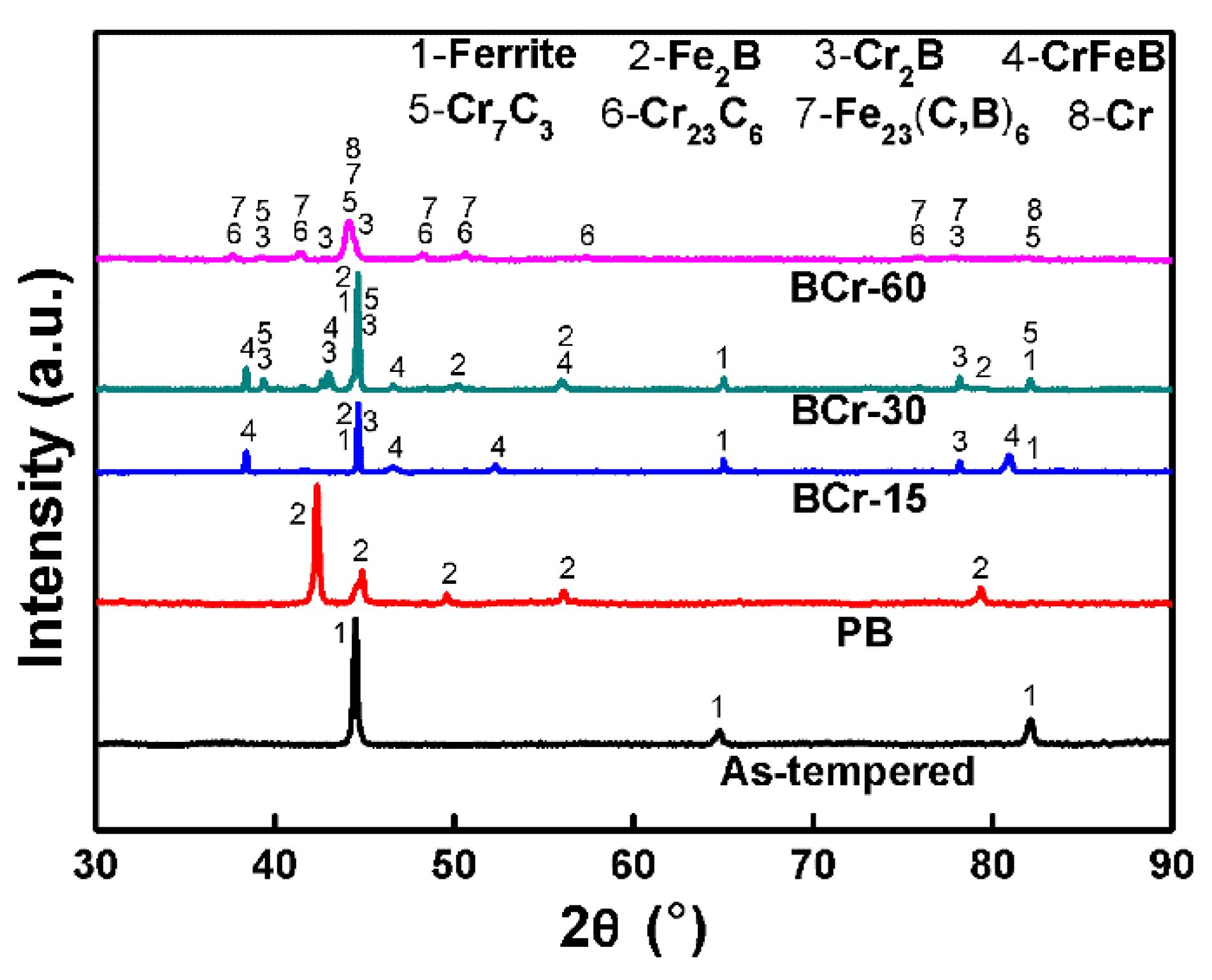
Figure 1. XRD patterns revealing the phases of various samples.
Coatings 10 00159 g001
Figure 2. Secondary electron imaging (SEI) and backscattering electron imaging (BSEI) images showing the microstructure of the starting material (a) and PB sample (b).
Coatings 10 00159 g002
Figure 3. Sectional microstructure of the BCr-15 sample: (a) BSEI image of the coating; (b,c) high magnification SEI and BSEI images corresponding to the white boxes in (a); (d) EDS line scanning in (a) (M to N).
Coatings 10 00159 g003
Figure 4. Microstructure and element distribution of the BCr-30 sample: (a) BSEI image of the coating; (b,d,e) high magnification BSEI images corresponding to the white boxes in (a); (c) EDS area scanning in (b); (f) EDS line scanning in (a) (M1 to N1).
Coatings 10 00159 g004
Figure 5. SEI and BSEI images showing the sectional microstructure and elemental distribution of BCr-60 sample: (a) sectional view of the coating; (b) EDS line scanning in (a) (M2 to N2); (c,d,f) high magnification images corresponding to the white boxes; (e) EDS area scanning and line scanning corresponding to the region in (d).
Coatings 10 00159 g005
Figure 6. Evolution of the coating thickness with the increasing of chromizing time.
Coatings 10 00159 g006
Figure 7. Sketch maps to exhibit the different growth modes during the chromizing process: (a) at early stage; (b) at late stage. Arrows present the main diffusion directions: the orange arrow mainly represents the diffusion direction of chromium, and the red arrow mainly represents the diffusion direction of boron. LCrP, LBCP, ICrP and IBCP represent lower Cr potential, lower B and C potential, increasing Cr potential and increasing B and C potential, respectively.
Coatings 10 00159 g007
Figure 8. The fitness of d n = K t for the changes of Cr-diffusion coating thickness d as a function of chromizing time t: (a) interface reaction controlled growth; (b) atom diffusion controlled growth.
Coatings 10 00159 g008
Figure 9. Sketch maps showing the microstructure evolution via the increasing chromizing time: (a) pre-boronizing; (bd) chromizing for 15, 30, and 60 min, respectively.
Coatings 10 00159 g009
Figure 10. Microhardness plotted as a function of distance to the surface of the three samples.
Coatings 10 00159 g010
Figure 11. SEI images showing the wear morphologies of the three samples: (a) BCr-15 sample; (b) BCr-30 sample; (c) BCr-60 sample.
Coatings 10 00159 g011
Figure 12. Friction coefficient plotted as a function of sliding friction time for different samples (a) and Mass loss (b).
Coatings 10 00159 g012