Article

The Microstructure and Selected Mechanical Properties of Al2O3 + 13 wt % TiO2 Plasma Sprayed Coatings

Faculty of Mechanical Engineering, Wrocław University of Science and Technology, Łukasiewicza 5, 50-371 Wrocław, Poland
*
Author to whom correspondence should be addressed.
Coatings 2020, 10(2), 173; https://doi.org/10.3390/coatings10020173
Submission received: 22 January 2020 / Revised: 7 February 2020 / Accepted: 11 February 2020 / Published: 13 February 2020

Abstract

:
The Al2O3 + TiO2 coatings are of the interest of surface technology and tribology due to their good wear resistance and enhanced toughness comparing to pure Al2O3 coatings. However, the detailed effect of the used feedstock powder, is often neglected. Here, this work focuses on the deposition of Al2O3 + 13 wt % TiO2 coatings by atmospheric plasma spraying (APS) method as well as on their microstructure, phase composition and selected mechanical properties, in the reference to the route of the powder feedstock preparation. The commercial powder Metco 6221 in agglomerated and sintered form was used as a feedstock material during spraying, due to the fact that, so far, sintered or cladded powders are the most studied ones. The 2k + 1 spray experiment allowed to evaluate the influence of two variables, namely spray distance and torch linear velocity, on the coating microstructure. Afterwards, the coating adhesion was measured by the means of pull-off test. The correlations between Vickers microhardness, fracture toughness (Kc) as well as the coating morphology and phase composition were investigated. Finally, the dry sliding wear resistance was studied by using Ball-on-Disc method.

1. Introduction

Plasma spraying is nowadays the primary method used commercially to deposit relatively thick coatings [1,2]. The continuous development of powder materials and spraying equipment, as well as better understanding of the spraying process itself, led to the application of thermal spraying in various fields: aircraft, automotive, power industry, and others [3,4,5,6,7]. One of the most commonly used material combinations for this technique is Al2O3 doped with TiO2 [2,8,9,10,11]. The commercial powders of the Al2O3–TiO2 system are usually available with 3 wt %, 13 wt %, and 40 wt % content of TiO2. In this work, Al2O3 + 13 wt % TiO2 (AT13) coatings deposited by APS were characterized.
It is already well known that AT13 coatings provide high wear resistance and fracture toughness [3,9,12]. Moreover, the use of Al2O3 and TiO2 in one powder particle can provide extended exploitation when compared to pure Al2O3. This is due to the fact that the conventional sandblasting applied to the materials with higher melting temperature (such as Al2O3) is often not a sufficient procedure to provide durable ceramic–metal bonding. The addition of TiO2 lowers the melting temperature of such powder and finally results in increased coating adhesion [13].
The motivation of studies on the abovementioned powder stems from the fact that, despite numerous studies and years of industrial applications of such APS coatings, surprisingly there are still unknown issues [14]. This comes from insufficient attention addressed to the used feedstock powder. Most of the studies present the comparison of coatings made from (i) various nanostructured powders (reconstituted into sprayable micrometric agglomerates) and well-known (ii) Metco 130 powder (in cladded form) [2,11,14,15,16,17,18].
Another important issue, is still a lack of understanding about the influence of formation of aluminum titanate (Al2TiO5) on the microstructure and mechanical properties of Al2O3-13 wt % TiO2 coatings [14]. Therefore, in the presented studies, AT13 coatings, derived from agglomerated and sintered powder, were sprayed according to the 2k + 1 design of experiment and analyzed in the terms of their morphology, microstructure, phase composition and resulting mechanical and wear properties, including: adhesion, microhardness, fracture toughness (Kc) and sliding wear resistance. Coatings sprayed from the agglomerated nanopowders, due to their favorable properties, were claimed to found a wide range of application, for example in printing industry and for tribological usage.

2. Materials and Methods

2.1. Materials

A commercially available powder (Metco 6221, Oerlikon, Switzerland) of Al2O3 + 13 wt % TiO2 (AT13) was used as a feedstock material for spraying process. The SEM micrographs (JEOL JSM-6610A, Jeol, Tokyo, Japan) showed that the particles had spherical morphology, as the powder was produced by agglomeration and sintering (Figure 1). Powders consisted of small evenly distributed particles of Al2O3 and TiO2. The nominal powder particle size range was equal in the range between 15 and 45 μm. The powder particles size was confirmed by laser diffraction granulometry (Horiba Partica LA-950 V2, Horiba Ltd., Kyoto, Japan). The results showed that powder had a volume–surface mean diameter dv50 equal to 33.3 μm and was characterized by narrow and monomodal particle size distribution. According to XRD analysis (Bruker AXS, Billerica, MA, USA), powder consisted of α-Al2O3, rutile-TiO2, and aluminum titanate Al2TiO5.

2.2. Spray Process

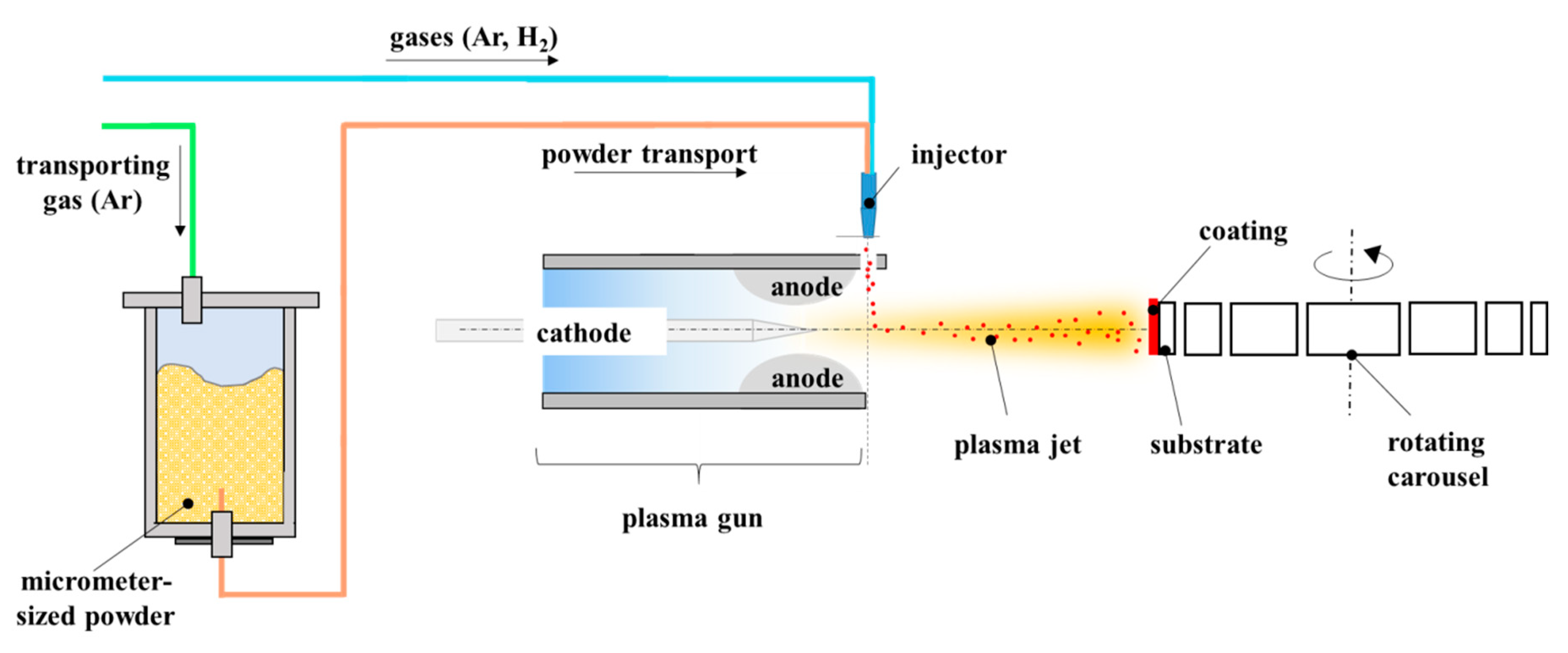
Atmospheric plasma spraying (APS) was used to process Al2O3 + 13 wt % TiO2 powders and deposit the coatings. The spray method is already well-established [19]. During spraying the micrometer-sized powders are heated by high-temperature plasma jet and propelled at high velocity to impact the substrate. Splats are created upon the impact of the liquid particle into the substrate and then the coating is formed, layer by layer [20].
Plasma spraying was carried out by the use of one cathode-one anode SG-100 plasma torch (Praxair, Indianapolis, IN, USA). The torch operated at a constant electric power of 35 kW. The working gases composition was Ar + H2 (45 slpm + 5 slpm) in each case. The plasma torch was fixed to a 6-axis Fanuc 2000 IA robot, whereas the substrates were mounted to the rotating carousel (Figure 2). The 2k+1 design of experiment (DoE) included two spray variables: spray distance and scan speed of the torch (that means the resultant linear velocity between the torch and rotating substrates). All spray process parameters and sample labels are collected in Table 1. The motivation behind selecting the mentioned variables comes from the literature study, and some of spray parameters have been investigated already, for example plasma power [21].
The feedstock material was injected radially into the plasma jet. The feed rate was about 20 g/min. Al2O3 + 13 wt % TiO2 powders were dried at a temperature of 120 °C for 3 h prior to spraying in order to avoid clogging of powder during feeding. The coatings were sprayed onto 25 mm stainless steel coupons with a thickness of 2 mm. Before spraying, the substrates were sand blasted by using corundum grit (F40 according to FEPA standard) and cleaned with ethanol in an ultrasonic bath.

2.3. Microstructural Characterization

The coatings’ free surfaces, as well as their cross-sections, were investigated to observe the microstructural features of deposits. The free surface of coatings was characterized in as-sprayed conditions. The metallographic sampling was performed in order to prepare cross-sections for further analysis. The samples were sectioned, mounted in an epoxy resin, and then grinded, and mirror-like polished. Afterwards, all samples were gold sputtered to reduce charging effect during scanning electron microscopy investigations. SEM observations were done by Phenom G2 Pro (Phenom-World, Eindhoven, The Netherlands). The main aim was to determine the morphology of coatings, including degree of melting of the particles, appearance of microcracks and voids, etc. The substrate/surface interface was analyzed as well.
Based on SEM micrographs the coating porosity and thickness were evaluated. The micrographs taken at magnification of 1000× were used for the porosity analysis. Then, the Image Analysis (IA) method was applied to count the percentage porosity area of coatings as this method allows counting both open and closed pores. The open source ImageJ software (version 1-50) was used for that purpose and analysis was carried out according to the ASTM E2109-01 Standard [23]. For each sample 20 images were processed to obtain reliable results. The thickness of coatings was measured by using SEM micrographs at 550× magnification. For each sample five measurements were taken at different locations along the coating cross-section. The average values and standard deviations were calculated, for both porosity and thickness.
Phase composition of the initial powders and coatings was determined by powder X-ray diffraction technique (XRD) using D8 Discover diffractometer (Bruker AXS, Karlsruhe, Germany) with CuKα radiation. The measurements were performed in the range 2θ = 10°÷80°, with 0.05° step size and 0.8 s/step counting time.
Finally, the roughness of coatings was measured by stylus profilometer (MarSurf PS 10, Mahr, Germany). The mean values of Ra, Rz, and Rt parameters were calculated. Three measurements on each sample were carried out and average and standard deviation were determined.

2.4. Mechanical Properties

The testing of mechanical properties was started by measurements of coating adhesion. The bond strength was determined by well-known pull-off test and was carried out by dedicated Elcometer 510 tester (Elcometer Instruments, Manchester, UK). A counterpart with the diameter of 10 mm was bonded to the coating using epoxy adhesive Distal Classic (Libella, Warsaw, Poland). Then, continuous pressure of 0.4 MPa/s was applied to the test pin, so the tension at the interface between the coating and counterpart was increased. Once the coating was pulled off, the numerical value of adhesion strength was indicated by the software. After the observations of coating surface and dolly surface, the failure mode was determined. The average value and standard deviation were calculated based on five measurements.
Subsequently, the microhardness of coatings was measured with Vickers penetrator under the load of 1.96 N (HV0.2) using the HV-1000 hardness tester (Sinowon Innovation Metrology, Dongguan, China), according to the standard [24]. For each coating 10 imprints at the cross-section were made and the average values, as well as standard deviations, were calculated.
Fracture toughness (Kc) for the coating–substrate system cannot be easily determined in a similar way as for the bulk materials. A popular approach in surface technology is a method based on measurement of cracks length, which occur in coating after Vickers penetration. The length of the cracks can be related to Kc value according to Palmqvist observation [25]. The further methodology depends on cracks identification and a ratio between l and a parameters (Figure 3). When the l/a ratio is in range from 0.1 to 1.5 then a Niihara model is used to calculate the fracture toughness [26]:
K C = 0.018 · H 0.6 · E 0.4 · 2 · a · l 0.5   [ M P a · m 1 / 2 ]
where:
  • H—Vickers hardness (MPa);
  • E—elastic modulus (MPa);
  • 2a—imprint diagonal (m);
  • l—average length of cracks (m).
However, when the ratio between l and a is higher than 1.5 then the equation proposed by Anstis et al. should be used [27]:
K C = 0.016 · ( E H ) 0.5 · P c 1.5 [ M P a · m 1 / 2 ]
where:
  • c = a + l—total length of crack (m);
  • P—maximum load of penetrant (N).
Ball-on-disc (BoD) dry sliding tests were carried out in rotating unidirectional configuration according to the ASTM G99-17 [30] using T-01 tribometer (Rtec Instruments, San Jose, CA, USA). According to the standard [30], average surface roughness (Ra) of 0.8 μm (or lower) is usually recommended. Therefore, coatings were grinded and polished before wear tests and their roughness was controlled after this process.
As a counterpart, 100Cr6 bearing steel balls of 6 mm diameter were used. The tests were performed under ambient conditions, over a distance of 500 m (10,000 cycles). The other parameters used for testing were as follows: relative sliding speed of 0.1 m/s, wear track radius of 6 mm, and normal load of 5 N. Three replicate wear tests were carried out and the average results were reported here.
BoD was conducted with the aim to determine the volume wear rate. The volume wear rate (Vw) was calculated by using as follow equation:
V w = V N · S   [ m m 3 N · m ]  
where:
  • V—volume (mm3);
  • S—sliding distance (m);
  • N—normal load (N).
The morphology of the wear tracks on the specimens was analyzed using scanning electron microscope (SEM) Phenom G2 Pro.

3. Results and Discussion

3.1. Coating Microstructure

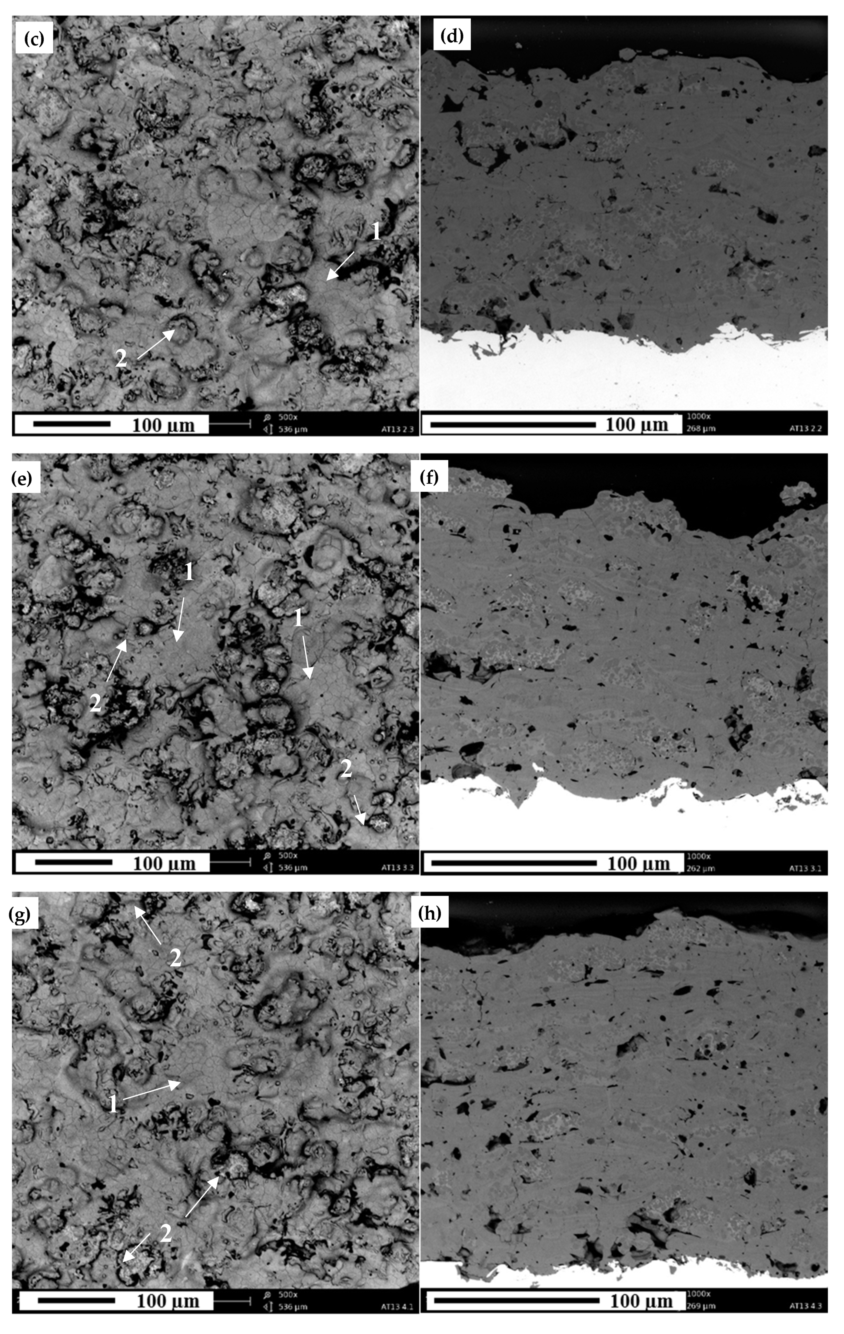
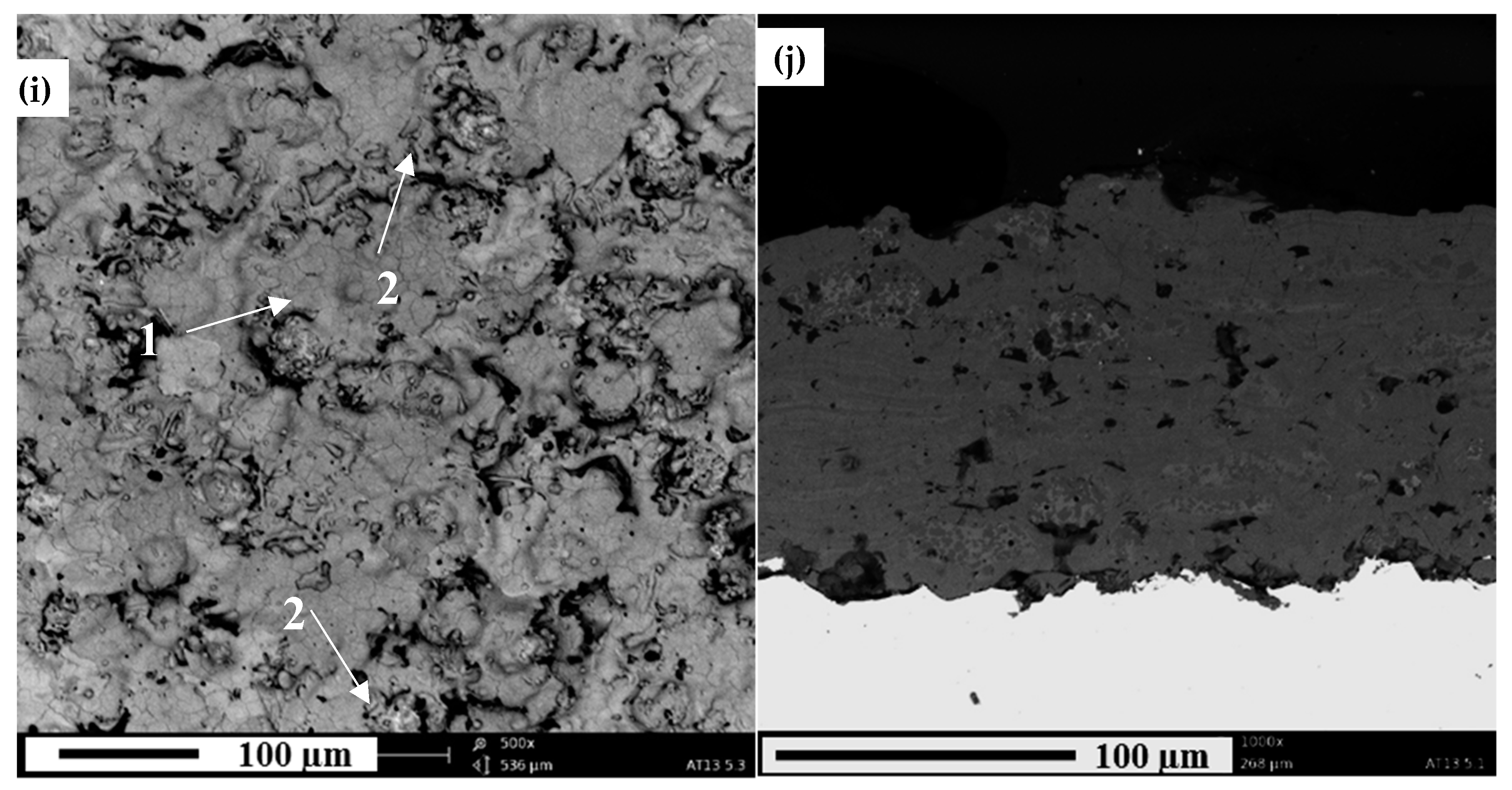
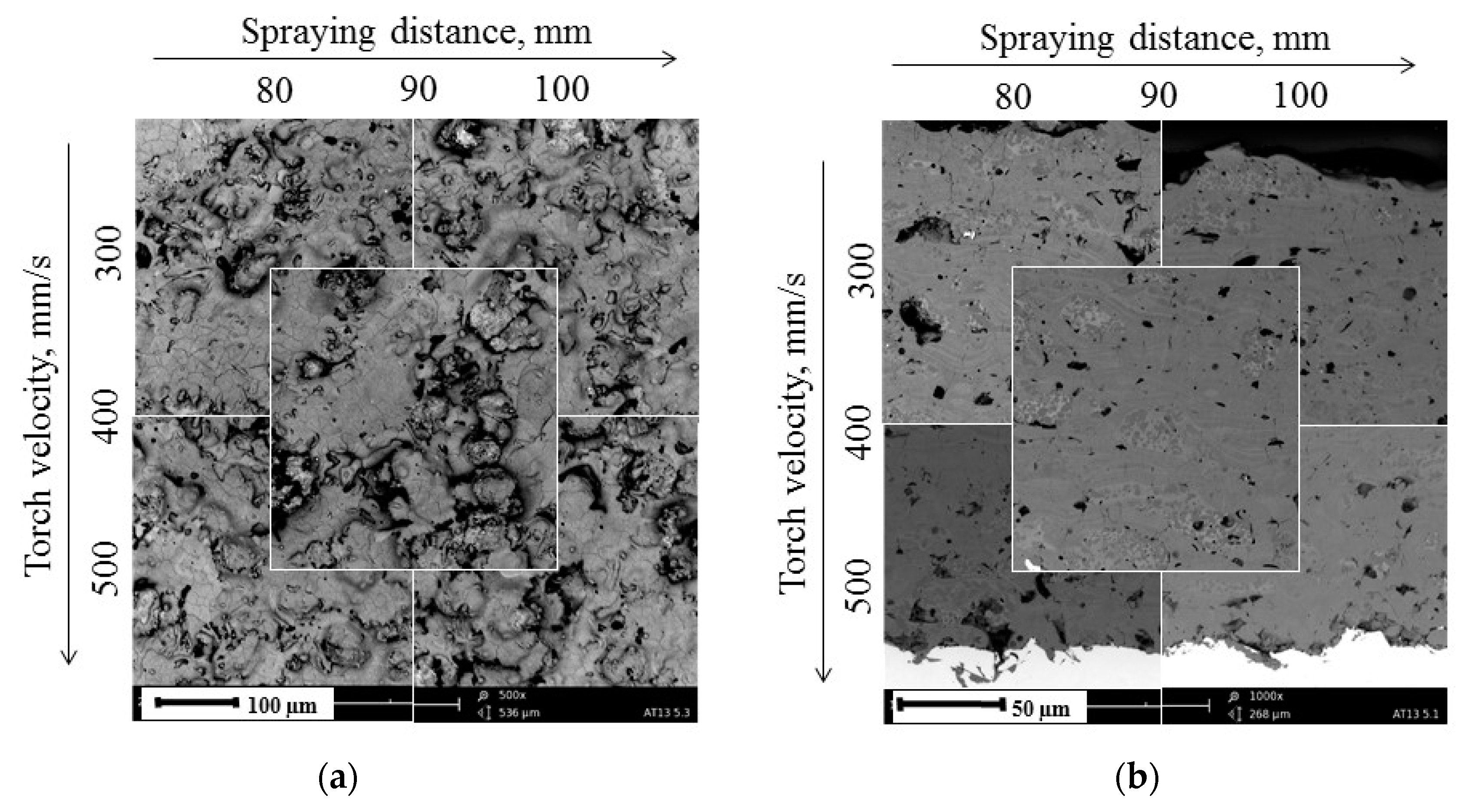
The micrographs of as-produced coatings are collected in Figure 4. It can be seen that the microstructure of coatings was influenced by the spray process parameters (summarized in Figure 5). While the shortest spray distance was used, the coatings were characterized by well-melted lamellas. This can be observed especially on their top surfaces (Figure 4a,c). The increase in the distance between the torch and the substrate caused some of the powder particles to cool down before hitting the substrate. As a result, those coatings (Figure 4e,g,i) were not that homogeneous, with less-flattened deposits, and their microstructure consisted of two regions: fully melted and partially melted areas. Similar results were obtained by Goberman et al. [15]. Furthermore, when comparing coatings sprayed with different torch scan velocities, some differences may be observed as well. Once the lowest torch scan speed was used (300 mm/s), the substrate and coating were highly exposed to heat generated by the plasma torch. As a result, some single inter- and intra-lamellar cracks are visible in those coatings (AT13-1 and AT13-4 presented in Figure 4b,h). On the contrary, once the torch scan speed was increased to 400 or 500 mm/s, the cracking of coatings was almost eliminated.
Dark areas visible in the coatings’ cross-section represent pores, voids, and cracks, which are inherent feature of APS coatings [2,9,11]. In all coatings, Al2O3 and TiO2 were evenly distributed [22,30]. It should be noticed that the substrate/coating interface did not reveal any discontinuities—it is well known that addition of TiO2 to Al2O3 improves adhesion between coating and substrate, due to lower melting temperature than of pure Al2O3 [9]. In each sample, the rough substrate asperities, being a result of abrasive blasting, were well covered by the Al2O3 + 13 wt % TiO2 splats.
The coatings intended for microstructure investigations were all sprayed with a similar number of spray passes. Coatings of thickness 130–230 μm were obtained. The deposition efficiency was the highest for samples AT13-1 and AT13-4 (equal approximately to 29 µm/pass and 28 µm/pass), so the lowest torch scan speed and shortest spray distance both had a positive impact on the process effectiveness.
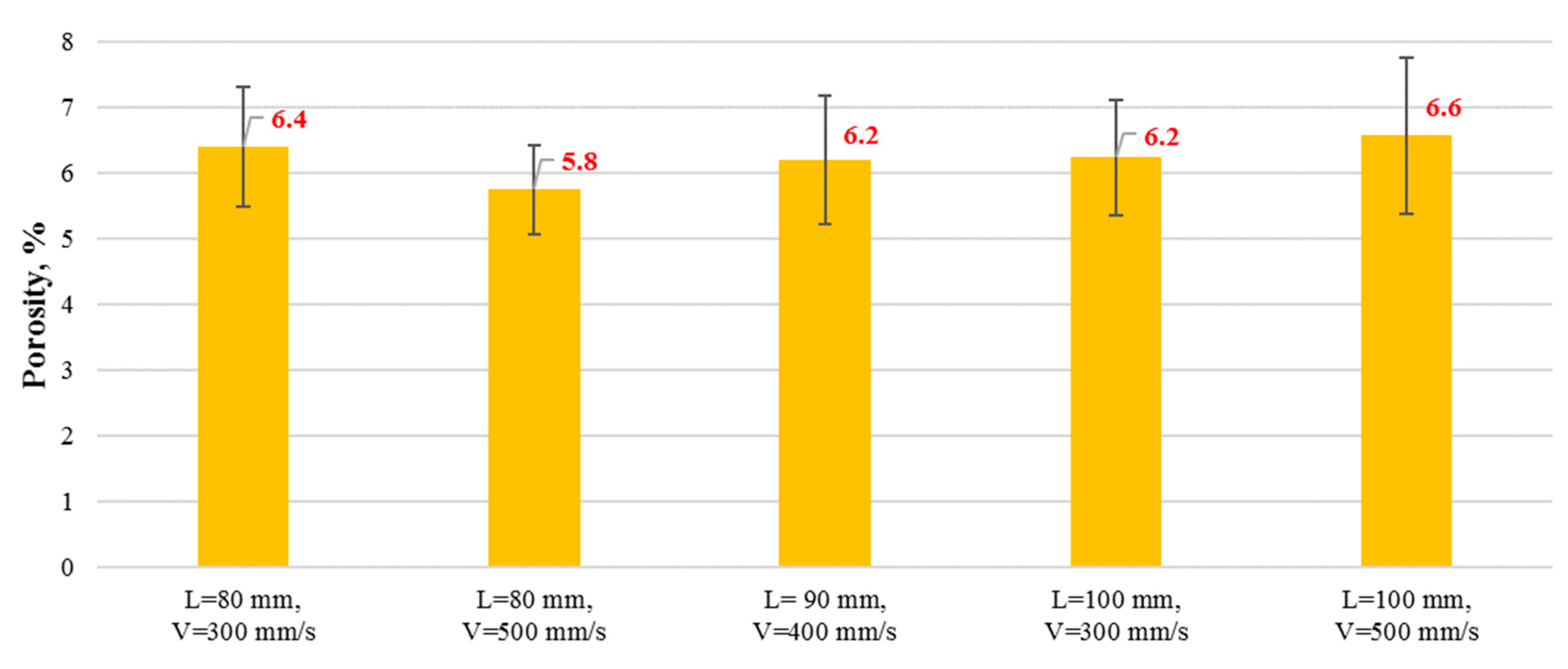
The porosity of the coatings was relatively low, as indicated by the results presented in Figure 6. Similar porosity values were found for all the coatings. They are in the range of results reported in other papers for coatings with similar chemical composition [14,31].
Finally, the roughness of coatings was investigated. The results are presented in Table 2. It can be seen that all surface topography parameters of the coatings are two to three times greater when comparing them to the substrate material just before spraying. Similar findings have been reported previously [32], so the presented roughness values can be considered as standard for these coatings. The greatest roughness was observed for coatings sprayed at the highest spray distance, which is also usually observed in thermal spraying.
Phase composition of deposited coatings is shown in Figure 7. It is clear that during spraying, the thermodynamically stable α-Al2O3 solidified in the metastable γ-Al2O3 [14]. These findings were observed in most of the works related to AT13 feedstock powder [2,9,17,32,33]: it is known that α-Al2O3 transforms irreversibly to γ-Al2O3 at temperature higher than ∼1000 °C, due to its preferential nucleation at high cooling rates [11,34,35,36]. Therefore, the presence of α-Al2O3 peaks indicated that some non-melted powder particles are still present in the deposited coatings. Figure 4 with SEM micrographs confirmed those findings, as discussed above.
When compared the phase composition of all sprayed coatings, it could be observed that the main difference lies in the intensity of aluminum titanate (Al2TiO5) peaks, especially for the shortest spray distance (AT13-1). This equimolar compound can be easily synthesized from alumina and titania, but decomposes below 1280 °C into single oxides of Al2O3 and TiO2 [37,38]. As there are significant differences between physical properties of the single Al2O3, TiO2, and Al2TiO5, an influence on the coating properties by the existence of Al2TiO5 can be expected. However, as shown in recent studies [37,39], the role and effect of Al2TiO5 on final coating properties is still not that clear, mainly due to its instability. The relationships between the presence of Al2TiO5 and resulting coatings properties is discussed in further sections.

3.2. Mechanical Properties

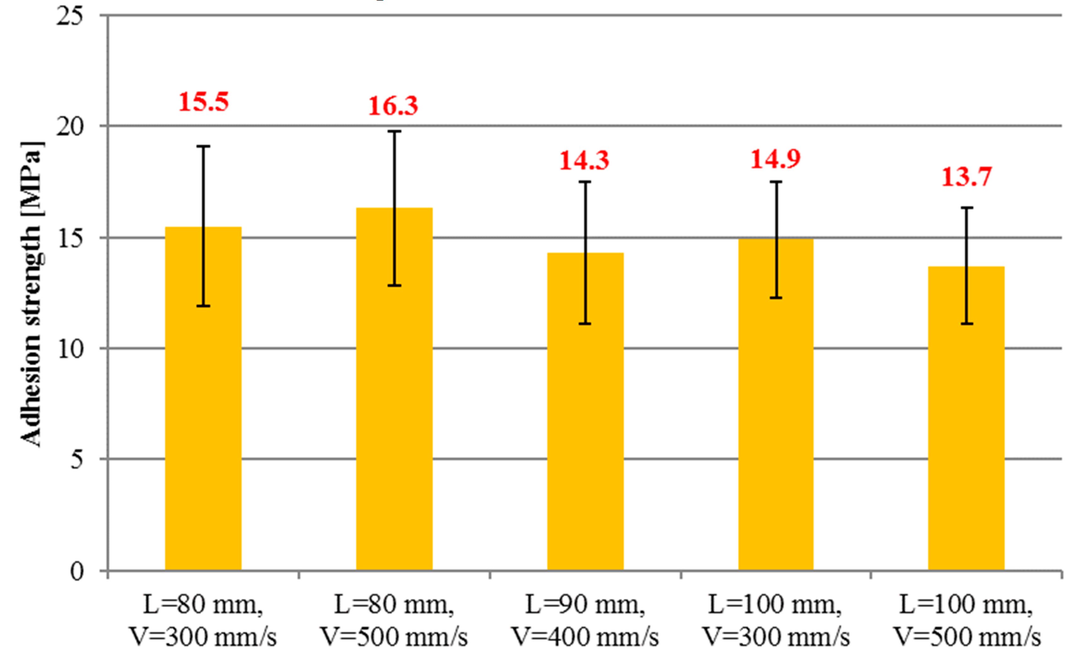
All coatings were investigated in pull-off test in order to determine their adhesion to the substrate. The results of bond strength testing are presented in Figure 8. The mean values of adhesion were ranging from 13.7 ± 2.6 MPa to 16.3 ± 3.5 MPa. In general, the coatings sprayed with shortest spray distance were characterized by higher adherence to the substrate. This can be explained by higher particle velocity influencing the impact momentum. It is believed that the increase in impact momentum improves the flattening of splats and allows better penetration of substrate asperities by deposits. The bond strength of presented coatings was similar to the results reported in literature, and indicated as sufficient for the exploitation [17].
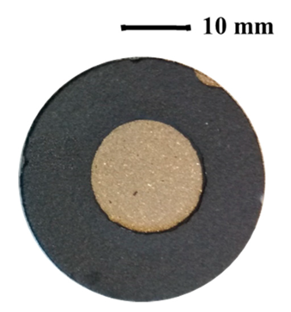
Afterwards, the surface of the dolly and the coating top surface were observed each time to assess the failure mode. The fractures, obtained in pull off tests, were mainly adhesive and had tendency to delaminate from the substrate, as shown in Figure 9. The relatively low adhesion of AT13 coatings sprayed by conventional micrometer-sized powders was also reported by other authors [2]. The adhesion of AT13 coatings may still be improved, mainly by the substrate preparation. The abrasive blasting with greater grits is possible in order to increase the substrate roughness prior spraying. Substrate pre-heating may be also considered. Some authors suggest the use of interlayers [32], e.g., nickel-based, to increase the bond-strength of alumina–titania coatings, and this may also be considered in further work.
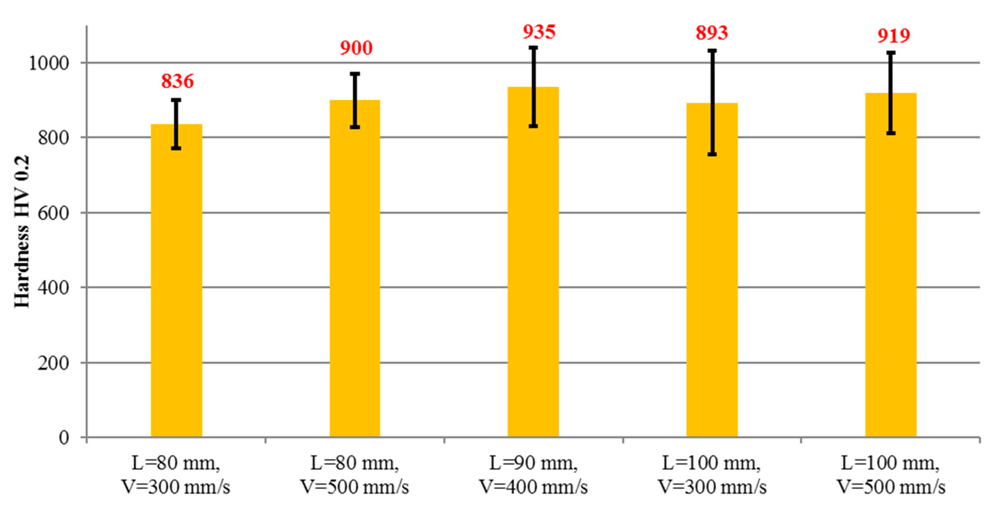
The Vickers microhardness of coatings is presented in Figure 10. The values are influenced by the presence of α-Al2O3, γ-Al2O3, rutile TiO2, and Al2TiO5 phases. In all coatings, α-Al2O3 phase was partially replaced by γ-Al2O3. Vargas et al. [31] reported that those phases in bulk materials are of hardness equal to 1600 and 1400 HV0.1, respectively. The obtained results are lower, due to the presence of Al2TiO5 phase, which is of lower hardness [31], as well as the fact that the presence of the following in the coatings—boundaries between lamellas, non-melted particles, porosity, and cracks—can significantly decrease the hardness in comparison to the bulk material. When considering the influence of spray parameters, it can be assumed that the best hardness is provided by the middle torch scan speed and spray distance (coating AT13-3). However, results are quite close to each other. It should also be noticed that coating sprayed from the shorter distance, characterized by better melting of powder particles and more homogeneous structure, show narrower range of standard deviation.
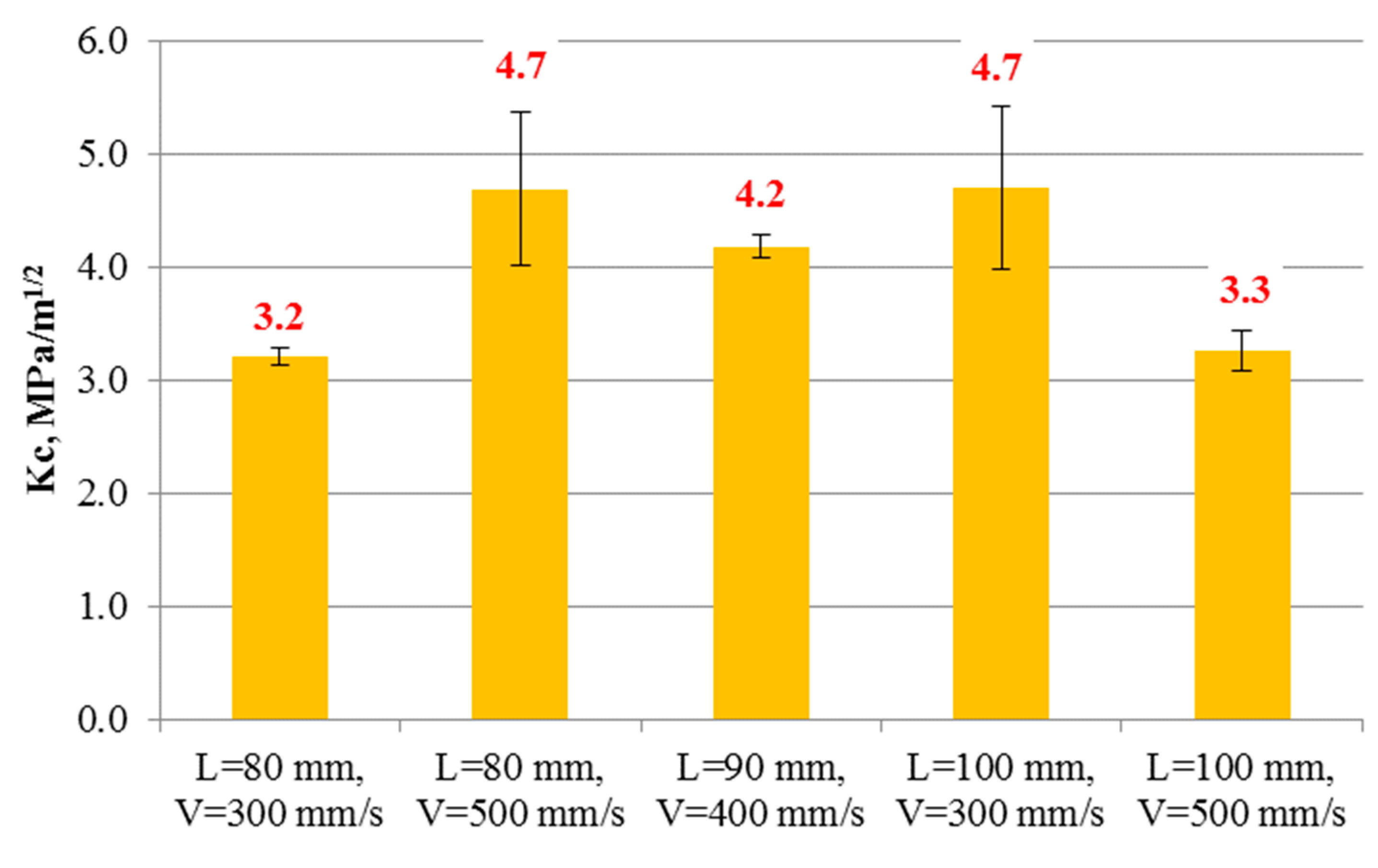
The fracture toughness values were calculated by using Anstis approach (Equation (2)). As confirmed by SEM and XRD investigations, non-melted particles were observed in the microstructure of theAT13-5 sample. Additionally, low cohesion between the particles was measured. As a consequence, as cracks propagated easily, low values of fracture toughness were obtained (see Figure 11) [2,40]. Coatings sprayed with the same parameters, but various spray distance (AT13-2) or torch scan speed (AT13-4), so in warmer conditions, were characterized by higher fracture toughness. As reported by H. Luo et al. [18], the effect of bi-modal microstructure may increase the Kc of Al2O3 + 13 wt % TiO2 coatings. This means that the well melted splats and partially melted particles, mixed together in the coating structure, can suppress the crack formation and propagation. However, the obtained results are representative for AT13 APS sprayed coatings. In the literature the fracture toughness of similar deposits is reported to be equal to 3.9 MPa∙m−1/2 [32,41].
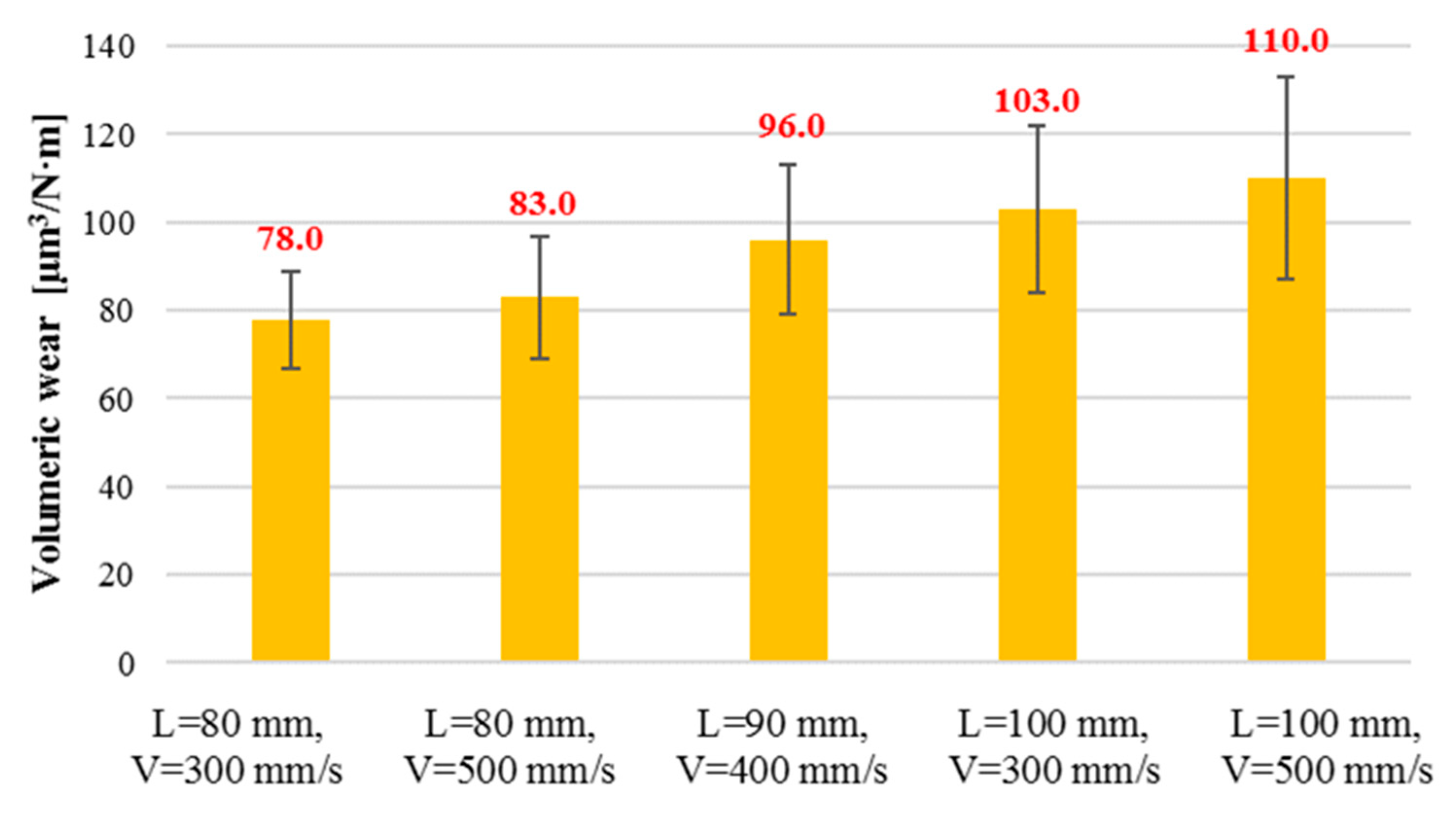
Finally, the Ball-on-Disc test allowed to study dry sliding wear resistance of coatings. Coatings dedicated to this investigation were sprayed once again, in order to obtain the similar thickness of 200 µm, due to the necessity of their grinding and polishing before wear tests. The results are presented in the form of volumetric wear in Figure 12. These results clearly indicate the strong influence of spray process parameters and coating microstructure on the wear resistance. The lowest wear was obtained for AT13-1 and AT13-2 coatings, which were sprayed with the shortest spray distance. The volumetric wear increased with the spray distance and was almost 1.5 times higher for AT13-5 when comparing with AT13-1. It should be pointed out that the high wear resistance was obtained for the coatings with lower content of Al2TiO5.
The findings can be correlated with SEM observations of wear track surfaces obtained after Ball-on-Disc. As presented in Figure 13, the AT13-1, AT13-3, and AT13-5 coatings showed different behavior when subjected to BoD testing. The wear track of AT13-1 did not reveal significant delamination or damage of coating, which corresponds to relatively low volumetric wear value. It predestines this type of coating for tribological application, for example for covering thread spools. Moreover, this coating is smoother than AT13-5, which contain lots of rough debris. Therefore, the mechanisms based on detachment of loosely bonded particles seemed to be much more dominant in coatings AT13-3 and AT13-5, produced at higher spray distance. These coatings were formed by less-melted particles. This caused much faster removal of material—during counterpart-to-coating contact, the non-fully melted or sintered powder particles were pulled out. This is in agreement with results of, e.g., Vargas et al. [30]. In their study, a strong correlation between fracture toughness and wear resistance was also observed. However, in the presented study, the fracture toughness was influenced by the bi-modal nature of coatings (especially AT13-3 to AT13-5). As discussed earlier, the less-melted regions could inhibit cracking of coating and increase the fracture toughness. But at the same time, the loosely bonded splats were not that resistant to the load applied in Ball-on-Disc testing.

4. Conclusions

In this paper the different spray variables were tested in order to produce Al2O3 + 13 wt % TiO2 coatings by atmospheric plasma spraying. The samples were characterized in the terms of their microstructure, phase composition, and various mechanical properties, which are required to provide extended lifetime of the component. The following findings can be summarized:
  • Coating microstructure and properties were clearly influenced by the feedstock characteristics. To obtain good coatings, the initial powder properties have to be considered, together with the spraying parameters: the shortest spray distance of 80 mm caused formation of homogeneous coatings with better-melted splats, as the particles impacted the substrate in fully molten state.
  • Beside the differences in coatings morphology and microstructure, also observed in the literature, some changes in the phase composition were also noticed. It could also be stated that the ratio of splat area (with γ-Al2O3 and anatase-TiO2) to area with non-melted agglomerates (with α-Al2O3 and rutile-TiO2) can be controlled by plasma spray parameters. The quantities of the phases depend also on the feedstock material.
  • The fracture toughness of coatings depends strongly on the spray parameters. Bi-modal microstructure consisting of well-molten and partially melted particles can provide better resistance (more than 20%) against crack formation than well-melted deposits.
  • The homogeneous structure of coating and relatively low porosity (below 7% in each case) allowed obtaining satisfactory results of wear resistance in BoD. The highest volumetric wear was observed for coatings sprayed with the longest spray distance of 100 mm, where microcracking, grooving, and detachment of loosely bonded particles were dominant during wear resistance testing. The shorter spray distance results in around 20% better wear resistance than a longer one. It was established that the spray process parameters have an effect on wear resistance of the coatings.
Further studies will concern mainly the improvement of coating adhesion. The influence of the different TiO2 additions on the Al2O3 + TiO2 coatings produced by APS and SPS is also under investigation.

Author Contributions

Conceptualization L.Ł. and M.M.; methodology, L.Ł. and M.M., investigation L.Ł., M.M. and A.N., resources M.M., writing—original draft preparation M.M., writing—review and editing L.Ł. and P.S., supervision A.A. All authors have read and agreed to the published version of the manuscript.

Funding

This research received no external funding.

Conflicts of Interest

The authors declare no conflict of interest.

References

  1. Sahab, A.R.M.; Saad, N.H.; Kasolang, S.; Saedon, J. Impact of Plasma Spray Variables Parameters on Mechanical and Wear Behaviour of Plasma Sprayed Al2O3 3% wt TiO2 Coating in Abrasion and Erosion Application. Procedia Eng. 2012, 41, 1689–1695. [Google Scholar] [CrossRef] [Green Version]
  2. Vicent, M.; Bannier, E.; Benavente, R.; Salvador, M.D.; Molina, T.; Moreno, R.; Sánchez, E. Influence of the feedstock characteristics on the microstructure and properties of Al2O3–TiO2 plasma-sprayed coatings. Surf. Coat. Technol. 2013, 220, 74–79. [Google Scholar] [CrossRef] [Green Version]
  3. Geaman, V.; Pop, M.A.; Motoc, D.L.; Radomir, I. Tribological properties of thermal spray coatings. Eur. Sci. J. ESJ 2014, 3, 154–159. [Google Scholar]
  4. Singh, V.P.; Sil, A.; Jayaganthan, R. Tribological behavior of plasma sprayed Cr2O3–3%TiO2 coatings—ScienceDirect. Wear 2011, 272, 149–158. [Google Scholar] [CrossRef]
  5. Steeper, T.J.; Varacalle, D.J.; Wilson, G.C.; Riggs, W.L.; Rotolico, A.J.; Nerz, J. A design of experiment study of plasma-sprayed alumina-titania coatings. J. Therm. Spray Technol. 1993, 2, 251–256. [Google Scholar] [CrossRef] [Green Version]
  6. Toma, F.-L.; Berger, L.-M.; Stahr, C.C.; Naumann, T.; Langner, S. Microstructures and Functional Properties of Suspension-Sprayed Al2O3 and TiO2 Coatings: An Overview. J. Therm. Spray Technol. 2010, 19, 262–274. [Google Scholar] [CrossRef]
  7. Szala, M.; Walczak, M.; Pasierbiewicz, K.; Kamiński, M. Cavitation Erosion and Sliding Wear Mechanisms of AlTiN and TiAlN Films Deposited on Stainless Steel Substrate. Coatings 2019, 9, 340. [Google Scholar] [CrossRef] [Green Version]
  8. Matikainen, V.; Niemi, K.; Koivuluoto, H.; Vuoristo, P. Abrasion, Erosion and Cavitation Erosion Wear Properties of Thermally Sprayed Alumina Based Coatings. Coatings 2014, 4, 18–36. [Google Scholar] [CrossRef] [Green Version]
  9. Stengl, V.; Ageorges, H.; Ctibor, P.; Murafa, N. Atmospheric plasma sprayed (APS) coatings of Al2O3–TiO2 system for photocatalytic application. Photochem. Photobiol. Sci. 2009, 8, 733–738. [Google Scholar] [CrossRef]
  10. Tomaszek, R.; Pawlowski, L.; Zdanowski, J.; Grimblot, J.; Laureyns, J. Microstructural transformations of TiO2, Al2O3+13TiO2 and Al2O3+40TiO2 at plasma spraying and laser engraving. Surf. Coat. Technol. 2004, 185, 137–149. [Google Scholar] [CrossRef]
  11. Żórawski, W.; Góral, A.; Bokuvka, O.; Lityńska-Dobrzyńska, L.; Berent, K. Microstructure and tribological properties of nanostructured and conventional plasma sprayed alumina–titania coatings. Surf. Coat. Technol. 2015, 268, 190–197. [Google Scholar] [CrossRef]
  12. Ibrahim, A.; Hamdy, A.S. Microstructure, Corrosion, and Fatigue Properties of Alumina-Titania Nanostructured Coatings. J. Surf. Eng. Mater. Adv. Technol. 2011, 1, 101. [Google Scholar] [CrossRef] [Green Version]
  13. Ghazali, M.J.; Forghani, S.M.; Hassanuddin, N.; Muchtar, A.; Daud, A.R. Comparative wear study of plasma sprayed TiO2 and Al2O3–TiO2 on mild steels—ScienceDirect. Tribol. Int. 2016, 93, 681–686. [Google Scholar] [CrossRef]
  14. Richter, A.; Berger, L.-M.; Conze, S.; Sohn, Y.J.; Vassen, R. Emergence and impact of Al2TiO5 in Al2O3-TiO2 APS coatings. Mater. Sci. Eng. 2019, 480, 012007. [Google Scholar] [CrossRef]
  15. Goberman, D.; Sohn, Y.H.; Shaw, L.; Jordan, E.; Gell, M. Microstructure development of Al2O3–13 wt % TiO2 plasma sprayed coatings derived from nanocrystalline powders. Acta Mater. 2002, 50, 1141–1152. [Google Scholar] [CrossRef]
  16. Góral, A.; Żórawski, W.; Lityńska-Dobrzyńska, L. Study of the microstructure of plasma sprayed coatings obtained from Al2O3–13TiO2 nanostructured and conventional powders. Mater. Charact. 2014, 96, 234–240. [Google Scholar] [CrossRef]
  17. Jordan, E.H.; Gell, M.; Sohn, Y.H.; Goberman, D.; Shaw, L.; Jiang, S.; Wang, M.; Xiao, T.D.; Wang, Y.; Strutt, P. Fabrication and evaluation of plasma sprayed nanostructured alumina–titania coatings with superior properties. Mater. Sci. Eng. A 2001, 301, 80–89. [Google Scholar] [CrossRef]
  18. Luo, H.; Goberman, D.; Shaw, L.; Gell, M. Indentation fracture behavior of plasma-sprayed nanostructured Al2O3–13 wt.%TiO2 coatings. Mater. Sci. Eng. A 2003, 346, 237–245. [Google Scholar] [CrossRef]
  19. Pawłowski, L. The Science and Engineering of Thermal Spray Coatings, 2nd ed.; Wiley: Chichester, UK, 2008; ISBN 978-0-471-49049-4. [Google Scholar]
  20. Fauchais, P.L.; Heberlein, J.V.R.; Boulos, M. Thermal Spray Fundamentals: From Powder to Part; Springer: New York, NY, USA, 2014; ISBN 978-0-387-28319-7. [Google Scholar]
  21. Wahab, J.A.; Ghazali, M.J.; Baharin, A.F.S. Microstructure and mechanical properties of plasma sprayed Al2O3—13%TiO2 Ceramic Coating. MATEC Web Conf. 2017, 87, 02027. [Google Scholar] [CrossRef] [Green Version]
  22. Pawlowski, L. Suspension and solution thermal spray coatings. Surf. Coat. Technol. 2009, 203, 2807–2829. [Google Scholar] [CrossRef]
  23. ASTM E2109-01 01 Standard Test Methods for Determining Area Percentage Porosity in Thermal Sprayed Coatings; ASTM: West Conshohocken, PA, USA, 2014.
  24. EN ISO 4516: 2004 Metallic and other Inorganic Coatings—Vickers and Knoop Microhardness Tests; Swiss Association for Standardization: Winterthur, Switzerland, 2004.
  25. Palmqvist, S. Occurrence of crack formation during Vickers indentation as a measure of the toughness of hard materials. Arch. Eisenhuettenwes 1962, 33, 629–634. [Google Scholar]
  26. Niihara, K. A fracture mechanics analysis of indentation-induced Palmqvist crack in ceramics. J. Mater. Sci. Lett. 1983, 2, 221–223. [Google Scholar] [CrossRef]
  27. Chantikul, P.; Anstis, G.R.; Lawn, B.R.; Marshall, D.B. A Critical Evaluation of Indentation Techniques for Measuring Fracture Toughness: II, Strength Method. J. Am. Ceram. Soc. 1981, 64, 539–543. [Google Scholar] [CrossRef]
  28. Pędzich, Z.; Piekarczyk, J.; Stobierski, L.; Szutkowska, M.; Walat, E. Twadość Vickersa i odporność na pękanie wybranych kompozytów ceramicznych. Kompozyty 2003, 3, 296–300. [Google Scholar]
  29. Michalak, M.; Łatka, L.; Sokołowski, P. Comparison of mechanical properties of the plasma sprayed coatings by powder and suspension. Weld. Technol. Rev. 2017, 89, 56–60. [Google Scholar]
  30. ASTM G99-17 Standard Test Method for Wear Testing with a Pin-on-Disk Apparatus; ASTM: West Conshohocken, PA, USA, 2016.
  31. Vargas, F.; Ageorges, H.; Fournier, P.; Fauchais, P.; Lopez, M.E. Mechanical and tribological performance of Al2O3-TiO2 coatings elaborated by flame and plasma spraying - ScienceDirect. Surf. Coat. Technol. 2010, 205, 1132–1136. [Google Scholar] [CrossRef]
  32. Yılmaz, Ş. An evaluation of plasma-sprayed coatings based on Al2O3 and Al2O3–13wt.% TiO2 with bond coat on pure titanium substrate. Ceram. Int. 2009, 35, 2017–2022. [Google Scholar] [CrossRef]
  33. Yao, S.H.; Su, Y.L.; Shu, H.Y.; Lee, C.I.; You, Z.L. Comparative Study on Nano-Structural and Traditional Al2O3-13TiO2 Air Plasma Sprayed Coatings and their Thermal Shock Performance. Key Eng. Mater. 2017, 739, 103–107. [Google Scholar] [CrossRef]
  34. Czanderna, A.W.; Rao, C.N.R.; Honig, J.M. The anatase-rutile transition. Part 1—Kinetics of the transformation of pure anatase. Trans. Faraday Soc. 1958, 54, 1069–1073. [Google Scholar] [CrossRef]
  35. Dachille, F.; Simons, P.Y.; Roy, R. Pressure-temperature studies of anatase, brookite, rutile and TiO2-II. Am. Mineral. 1968, 53, 1929–1939. [Google Scholar]
  36. Shaw, L.L.; Goberman, D.; Ren, R.; Gell, M.; Jiang, S.; Wang, Y.; Xiao, T.D.; Strutt, P.R. The dependency of microstructure and properties of nanostructured coatings on plasma spray conditions. Surf. Coat. Technol. 2000, 130, 1–8. [Google Scholar] [CrossRef]
  37. Berger, L.-M.; Toma, F.-L.; Scheitz, S.; Trache, R.; Börner, T. Thermisch gespritzte Schichten im System Al2O3–Cr2O3–TiO2—Ein Update. Mater. Werkst. 2014, 45, 465–475. [Google Scholar] [CrossRef]
  38. Freudenberg, F. Etude de la réaction à l’état solide Al2O3 + TiO2 → Al2TiO5: Observation des structures: ThéseVÉ cole polytechnique fe´de´rale de Lausanne EPFL. EPFL Lausanne 1988, 709. [Google Scholar]
  39. Berger, L.-M. Tribology of thermally sprayed coatings in the Al2O3-Cr2O3-TiO2 system. In Thermal Sprayed Coatings and Their Tribological Performances; Engineering Science Reference; IGI Global: Hershey, PA, USA, 2015; pp. 227–267. ISBN 978-1-4666-7489-9. [Google Scholar]
  40. Łatka, L.; Niemiec, A.; Michalak, M.; Sokołowski, P. Tribological properties of Al2O3+ TiO2 coatings manufactured by plasma spraying. Tribology 2019, 1, 19–24. [Google Scholar] [CrossRef]
  41. Dejang, N.; Watcharapasorn, A.; Wirojupatump, S.; Niranatlumpong, P.; Jiansirisomboon, S. Fabrication and properties of plasma-sprayed Al2O3/TiO2 composite coatings: A role of nano-sized TiO2 addition. Surf. Coat. Technol. 2010, 204, 1651–1657. [Google Scholar] [CrossRef]
Figure 1. SEM image of Al2O3 + 13 wt% TiO2 powder in the delivery condition.
Coatings 10 00173 g001
Figure 2. The spray process configuration scheme (inspired by [22] copyright Elsevier 2008).
Coatings 10 00173 g002
Figure 3. Geometry and vertical section of cracks around Vickers print [28]: (a) radial-median mode, (b) Palmqvist mode, and (c) exemplary crack after Vickers indentation [29].
Coatings 10 00173 g003
Figure 4. Free surface (left side) and cross sections (right side) of produced coatings: (a,b)—AT13-1 (L = 80 mm; V = 300 mm/s); (c,d)—AT13-2 (L = 80 mm; V = 500 mm/s); (e,f)—AT13-3 (L = 90 mm; V = 400 mm/s); (g,h)—AT13-4 (L = 100 mm; V = 300 mm/s); (i,j)—AT13-5 (L = 100 mm; V = 500 mm/s); 1—fully melted splats, 2—non-melted powder particles.
Coatings 10 00173 g004aCoatings 10 00173 g004bCoatings 10 00173 g004c
Figure 5. The correlation between spray process parameters and (a) free-surface topography and (b) microstructure of coatings cross sections.
Coatings 10 00173 g005
Figure 6. Mean values of coatings porosity.
Coatings 10 00173 g006
Figure 7. XRD of as-sprayed coatings and as-delivered powder.
Coatings 10 00173 g007
Figure 8. Adhesion strength of AT13 coatings.
Coatings 10 00173 g008
Figure 9. AT13-1 coatings after pull-off tests.
Coatings 10 00173 g009
Figure 10. Mean values of coating’s microhardness.
Coatings 10 00173 g010
Figure 11. The fracture toughness of AT13 coatings.
Coatings 10 00173 g011
Figure 12. The results of Ball-on-Disc test for AT13 coatings.
Coatings 10 00173 g012
Figure 13. The wear track surface of: (a) AT13-1 (L = 80 mm; V = 300 mm/s), (b) AT13-3 (L = 90 mm; V = 400 mm/s), and (c) AT13-5 coating (L = 100 mm; V = 500 mm/s): 1—smooth wear track, 2—rough debris.
Coatings 10 00173 g013
Table 1. The process parameters and sample labelling.
Sample CodeSpray Distance L, mmTorch Velocity V, mm/sElectric Power, kW
AT13-18030035
AT13-280500
AT13-390400
AT13-4100300
AT13-5100500
Table 2. Mean values of coatings roughness.
Ra, µmRz, µmRt, µm
AT13-17.6 ± 0.0650.1 ± 1.2461.9 ± 4.20
AT13-27.8 ± 0.0151.3 ± 2.2162.3 ± 4.49
AT13-37.8 ± 0.0450.5 ± 1.0261.6 ± 3.54
AT13-47.9 ± 0.0450.2 ± 0.9261.9 ± 2.39
AT13-58.0 ± 0.0452.7 ± 0.9562.7 ± 0.29
substrate3.0 ± 0.0122.4 ± 0.1425.8 ± 1.54