Article

Mechanical Behavior and Damage of Zinc Coating for Hot Dip Galvanized Steel Sheet DP600

1
Key Laboratory of Metallurgical Equipment and Control Technology, Ministry of Education, Wuhan University of Science and Technology, Wuhan 430081, China
2
Hubei Key Laboratory of Mechanical Transmission and Manufacturing Engineering, Wuhan University of Science and Technology, Wuhan 430081, China
*
Author to whom correspondence should be addressed.
Coatings 2020, 10(3), 202; https://doi.org/10.3390/coatings10030202
Submission received: 12 January 2020 / Revised: 20 February 2020 / Accepted: 23 February 2020 / Published: 26 February 2020

Abstract

:
Advanced high strength galvanized steel sheet has been one of the dominant materials of modern automotive panels because of its outstanding mechanical properties and corrosion resistance. The zinc coating thickness of hot dip galvanized steel sheet is only about 10–20 μm, which is a discarded object on the macro level. However, it is obvious to damage and impact on stamping performance. Therefore, this paper takes zinc coating as the research object and builds its mechanical constitutive model based on a nano-indentation test and dimensional analysis theory. We separated the zinc coating from the galvanized steel substrate and constructed a sandwich material model by introducing a cohesive layer to connect the zinc coating and the steel substrate. We obtained the interface binding energy between the zinc coating and the steel substrate through the nano-scratch test. The accuracy of the model is verified by the finite element analysis of hemispherical parts. We used the five-layers element model with 0 thickness cohesive layer to simulate the zinc coating damage of galvanized steel sheet. The hemispherical part drawing experiment is used to verify the feasibility of the finite element analysis results. The results demonstrate that it is more accurate to consider the finite element numerical simulation of the zinc coating, introducing the cohesive element to simulate damage between the coating and the substrate. Drawing depth, stamping force, and the strain of the numerical simulation are closer to the experimental results.

1. Introduction

Galvanized advanced high strength steel (AHSS) has become the dominant material of automotive lightweight because of its superior strength, elongation, and outstanding corrosion resistance, which can follow the requirements of collision safety, energy saving, emission reduction, and environmental protection [1]. The coating is an ultra-thin material galvanized on the upper and lower surfaces of the steel substrate. There are two galvanizing methods: hot-dip galvanizing and electro galvanizing [2]. The thickness of the zinc coating is about 8 μm [3], which represents a slight difference between galvanizing methods. It neglects this level of magnitude on macroscopic scales. But zinc coating layer makes the surface characteristics of galvanized steel different from that of non-galvanized steel. These zinc coating layers are easy to damage in severe plastic deformation under external pressure and sliding friction [4,5,6]. It will also affect the formation of welding joints of stamping parts [7]. Typical damages of the coating layers are cracking and powdering flaking. The exfoliated coating adheres to the surfaces of the steel and die, resulting in falling, wearing, and affecting the stamping formability of the steel sheet [8,9]. Therefore, it is of great practical significance to study the mechanical properties of the zinc coating and its influence on the deformation of galvanized AHSS during stamping forming.
Zinc plating is an alloying process, and its element content will influence the performance of the galvanized layer. Vourlias et al. [10] studied the effect of alloying elements on the interfacial reaction of the galvanized coating. They found that the concentration and distribution of alloying elements played an important role in the phase growth. To improve the coating quality of high strength DP steel, a nickel layer was pre-electroplated on the steel substrate before galvanizing, and an enhancement in the coating quality was discovered [11]. Parisot et al. [12] confirmed the damage mechanisms at work in three different microstructures of a zinc coating on an interstitial-free steel substrate under tension, plain strain, and expansion loading. Two main fracture mechanisms, intergranular fracture and transgranular boundary fracture, were created in cold-rolled coatings, tempered cold-rolled coatings, and uncrystallized coatings. Further investigation shows that the damage between the galvanized layer and substrate depends on the different mechanical behavior and thickness of intermetallic compounds [13]. Petit et al. [14] investigated the galvanization ability of a high strength chromium-rich TRIP800 (transformation induced plasticity steel). Under different loads and deformation conditions, zinc coating also shows different mechanics. The damage behavior of different galvanized steel sheets under tension-bending conditions was explored by Yu et al. [15]. They discovered that the exfoliating and scratching of coating are two types of surface damage. To quantify the damage of galvanized coating, Xu et al. [16] suggested a parameter to illustrate the powdering of galvanized coating and its validity by double reverse Olsen test. Song and Sloof [17] introduced a “macroscopic atomic model” to assess the adhesion of the zinc coating for hot-dip galvanized dual phase steel. Adhesion force is an important property of coated steel, which concluded the quality of the coating. The damage of the coating in the stamping process results from the relative sliding friction between the steel sheet and the die surfaces. Wang et al. [9] considered the evolutionary process of galling of galvanized AHSS DP590 (dual-phase steel) under the condition of friction coupling plastic bending deformation. First, the coating is cracked because of tensile deformation. Then, further powdering of the coating resulted in a notable increase in the surface roughness of the contact interface. Die wear and surface galling of stamping parts will be caused because of the adhesion effect of coating. Therefore, the coating layer must be considered as an essential research branch of AHSS stamping.
Numerical simulation is an effective tool and method to study the strain distribution stamping forming [18]. As a non-negligible factor, we must consider the coating in the numerical simulation of stamping forming. The upper and lower surface of the galvanized steel sheet is zinc coating, and the intermediate substrate is a steel sheet. We can understand it as three-layers of composite material, like a sandwich equivalent to the stamping of multiple layers of material. It includes multi-scale modeling of materials [19], stamping formability [20,21,22], spring-back [23,24], and evolution of interface structure [25]. A three-dimensional finite element (FE) simulation of a thin zinc coating on a galvanized steel sheet has been performed by taking the multicrystalline structure of the coating into account [26]. In addition, Ucun and Aslantas [27] simulated the mechanical properties and force status of the cutting tools with different coating types by the method of single layer and multi-layer finite element modeling. Lee et al. [28] simulated the deep drawing of galvanized steel with a multi-layer element model, and the interface between substrate and coating was set to be adherent. Kim et al. [29] studied the fracture of the coating layer of galvanized steel using V-bending test and numerical simulation of the solid element. The results show that the coating and substrate begin to failure when the local plastic equivalent plastic reaches 0.26–0.28. Bettaieb et al. [30] proposed a solid shell element to describe the coating under T-bending based on the enhanced assumed strain (EAS) technique and the assumed natural strain (ANS) technique, that can avoid locking problems caused by the large aspect ratio of ultra-thin coating elements. It is shown that a higher accuracy simulation of coating can be achieved by using such a solid shell element.
Although the coating is taken into consideration in the above studies, the element model of numerical simulation still cannot describe the deformation model of the coating and substrate of galvanized AHSS. Therefore, in this paper, a coupled element model based on solid shell element and shell element is introduced to simulate the deformation of galvanized AHSS sheet, which recognized the scale effect of the coating. The mechanical properties of the coating and substrate were obtained by nano-indentation and uniaxial tensile test as the input condition of numerical simulation. It employs the dynamic friction coefficient considering the positive pressure between the stamping interfaces. The stamping forming experiment is developed and implemented, and we compare the numerical simulation results are compared with the experimental results. It is used to prove the numerical simulation accuracy of the coupled element model.

2. Mechanical Behavior of Zinc Coating

The hot dip galvanized cold rolled steel DP600 with a thickness 1.2 mm was chosen as the research object, which is the most applied steel in the galvanized advanced high strength steel sheet. The composition of the steel substrate is C-0.13%, Si-0.36%, Mn-0.168%, Alt-0.048%, and the composition of the zinc coating is mainly expressed by the thickness of the coating, as shown in the following experimental results. The stress–strain curves of the substrate and the coating layer of the steel sheet will be obtained by the experimental method. The detailed process of the experiment is as follows.

2.1. Constitutive Model of Zinc Coating

By inspecting the cross-section electron microscopic (SEM) results of many specimens, the thickness of the zinc layer is between 14.5–15.3 μm. Therefore, the thickness of DP600 zinc coating is set to 15 μm, that is to say, the upper and lower surfaces of the substrate have a zinc coating with a thickness of 15 μm, which is like a sandwich material. SEM measured the cross-section morphology of the specimens displayed in Figure 1, and the thickness of the zinc coating is 15.1 μm.
The uniaxial tension test is used to get the mechanical properties of the steel substrate. To study the mechanical properties of the steel substrate, it is necessary to remove the zinc coating. We analyzed the surface morphology of a steel sheet before and after acid pickling, the results as shown in Figure 2. The surface material of the coating layer is much looser than that of the substrate. It can be seen that the zinc coating is a thin film covering the surface of the substrate, and its related to the galvanizing process. This is also one of the main reasons that the coating is easily powdered and damaged when it is deformed and then affects the mechanical properties of the steel. Therefore, the mechanical properties of galvanized steel sheets and non-galvanized steel sheets should be different.
Samples are taken respectively on R00 degrees, R45 degrees, and R90 degrees from rolling direction, and then uniaxial tensile tests are executed. The Z050 electronic universal tensile testing machine was used to carry out the uniaxial tensile tests on the samples. The maximum experimental force is 50 kN, and it is set up with vertical and horizontal extensometer to measure the anisotropic parameters. It offers detailed mechanical parameters in Table 1. The results show that zinc coating involves a definite effect on the mechanical properties of steel sheet. Although the results have not been able to make a conclusion of consistency enhancement or reduction. Therefore, the zinc coating should not be neglected in a galvanized steel sheet, and it should establish its independent mechanical model to reveal accurately the mechanical characteristics of galvanized steel sheet.
Nano-indentation experiment can obtain the young’s modulus, hardness and load displacement curve of zinc coating. Based on the dimensional analysis method, the material constitutive model of the zinc coating is constructed by processing these data. The detailed measurement principle of nano-indentation is shown in Figure 3. The hmax is the maximum depth of the indentation, the hf is the residual depth, and the Pmax is the maximum load. Contact depth hc refers to the depth of the contact between the pressure head and the pressed object when pressed into the measured material, as shown in Figure 3b. Depending on the power function law proposed by Oliver and Pharr [31], the loading and unloading curves are analyzed and fitted.
The prototype of the in-situ nano-mechanical tester used in this experiment is TI750, which is produced by Hysitron® company in the Irvine city, California, USA. The maximum load of the instrument is 30mN, and the minimum load is 70 nN. It makes the indenter of Berkovich diamond, whose elastic modulus is Ei = 1141Gpa and Poisson’s ratio is vi = 0.07. The test temperature is 25 °C, the loading mode is load control, and the constant strain rate is 0.05 s−1. The results of loading and unloading curves are shown in Figure 4. It is assumed that the stress–strain curves of zinc coating are power hardening function models, as shown in Equation (1).
σ = { E ε σ σ y R ε n σ σ y ( R = E n σ y 1 n )
where E is the elastic modulus of the zinc coating which has been obtained by the above analysis. Only yield strength σy and hardening index n need to be solved.
σ = { E f ε σ σ y R ε n σ σ y ( R = E f n σ y 1 n )
σ = { 135000 ε σ σ y 1024.45 ε 0.08586 σ σ y
In this paper, the two unidentified parameters are solved by the combination of dimensionless analysis and finite element numerical simulation. The related parameter dimensions are shown in Table 2 as follows. According to the above analysis and test results, the elastic modulus of the zinc coating is 135 GPa. The mathematical model of stress–strain is shown in Equation (2) and the curve is shown in in Figure 5a. The finite element simulation of Nano-indentation is carried out by using the model, and it shows the compared results with the test results in Figure 5b. The deviation of the two curves is within 2%, which shows that the model can reflect the mechanical properties of the coating. The finished constitutive model of the zinc coating is given in Equation (3). The yield stress is 647.72 Mpa and the yield strain is 4.79814 × 10⁻³.

2.2. Interface Binding Energy between Zinc Coating and Substrate

The interface binding force between the coating and the substrate refers to the binding strength between the coating and the substrate. The external force required by the coating per unit area from the substrate which is an important index for testing binding strength between the coating and substrate. The sliding module of the UMT-TriboLab® friction test machine is used in this experiment. The spherical point pressure head with a cone angle of 120° and a radius of 200 μm is used. After the surface is polished, DP600 galvanized steel sheet is preloaded with the force of 0.6 kg for a continuous 10s, the linear loading force of the maximum positive load is 2.0 kg, and the duration is 120 s. It shows its load condition in Figure 6a. The morphology of the scratch is measured, and the results are displayed in Figure 6b. From the analysis of the results, the transverse displacement of the scratch initiation point and the interface failure point are (−11.12501, −12.663326), the length is about 1.538 mm, and the longitudinal depth is 15.1 μm.
Figure 7 is the change of tangential load Fx, friction coefficient μ and acoustic signal AE with time t. The analysis shows that when the interface is broken, the tangential force will decrease sharply or to 0, and then gradually increase, which leads to the clear fluctuation of the friction coefficient and sound signal at the fracture point (the breakpoint in the Figure 7). As the polishing surface of the sample cannot be smooth, there may be impurities in the coating layer, and it does not treat the surface of the substrate which represents the coating and the substrate a staggered state of convex and concave. Therefore, the tangential force, friction coefficient and acoustic signal curve are not linear changes, but small fluctuations. However, there will be large changes in the interface failure. Considering this, we can judge the point of the critical load. Combined with the breakpoints of the curves, interface failure time is 92.22 s, and the corresponding critical load is 15.76 N, and the critical friction coefficient is 0.202.
The failure of the coating results from the joint action of three stress states, which are the static pressure stress formed by the loading load, the friction stress of the contact area when the pressure head slips on the surface of the specimen, and the residual stress in the coating. It is well known that the pressure head is spherical and its radius Ri = 200 μm. The contact radius of the indenter and coating is obtained in Equation (4) [32].
a 3 = 3 4 L R i ( 1 V s 2 E s 1 V i 2 E i )
where a is the contact radius between the indenter and the coating, L is the critical load, and V and E are Poisson’s ratio and elastic modulus (s, i mark substrate and indenter). When the indenter is rigid, the Ei means infinity, and the Equation (4) can be reformulated as Equation (5) [32].
a 3 = 3 4 L R i 1 V s 2 E s
Without considering the plastic deformation of the substrate, it shows the stress distribution in the contact area in Equation (6) [32].
{ σ x x = L 2 π a 2 ( 1 2 V s ) σ y y = L 2 π a 2 ( 1 2 V s ) σ z z = σ x y = σ y z = σ z x = 0
where σxx, σyy, and σzz are three normal stress components, while σxy, σyz, and σzx are three shear stress components.
According to the above stress analysis, because the coating is very thin, it can be assumed that the strain of the coating will not change with its thickness. The strain of the coating and the substrate is the same at the interface. The coating strain in front of the indenter can be described as shown in Equation (7) [32].
{ ε x x = 1 E s [ σ x x V s σ y y ] = 1 E s { L 2 π a 2 ( 1 + V s ) [ ( 1 2 V s ) ( 4 3 V s ) 3 π μ 8 ] } ε y y = 1 E s [ σ y y V s σ x x ] = 1 E s { L 2 π a 2 ( 1 + V s ) [ ( 1 2 V s ) 3 π V s μ 8 ] } ε z z = V s E s [ σ x x + σ y y ]
where εxx, εyy, εzz are three normal strain components and μ is the coefficient of friction.
The strain of Z is expected to be very small and can be ignored. Using the above strain field, the elastic deformation energy stored in each element in the coating can be evaluated and the residual stress in the coating is considered. The detailed equations are described as follows [32]:
U e l a s t i c = E f 2 [ ε x x   2 + ε y y   2 ]
ε x x = ε x x + σ r e s ( 1 V f ) E f
ε y y = ε y y + σ r e s ( 1 V f ) E f
where Uelastic is the elastic deformation energy per unit volume, εxx and εyy are residual strains, σres is the residual stress of the zinc coating, and Vf and Ef are the Poisson’s ratio and elastic modulus of coating.
The thin coating in front of the indenter releases its elastic deformation energy through interfacial delamination and coating cracking, which leads to the failure of the coating. It is assumed that the coating failure area under the critical load is a semi-annular zone separated from the substrate and the radius is c, then the expression of the total energy stored in the coating is shown as Equation (11).
U = E f 2 ( ε x x 2 + ε y y 2 ) π c 2 t 2 W π c 2 2 2 ( π + 2 ) c γ f t
where U is the total energy stored in the coating, t is the thickness of the coating, c is the radius of the failed part of the coating, W is the interface binding strength of the interface, t is the plastic dissipation at the crack tip in the separation process, and γf is the surface energy of the coating.
The failure behavior of the thin coating will continue when the energy released by the failure behaviors such as delamination and spalling of the coating is larger than that of the interface and surface energy. Therefore, the following Equation (12) [33] can be consulted from the Griffith energy balance condition. It will generate the interface binding strength of the interface, as shown in Equation (13) [33]. Depending on the experimental results and the above calculation, and neglecting the residual stress of the coating, the interface binding strength between the coating and the substrate is obtained, as shown in Table 3.
U c = E f 2 ( ε x x 2 + ε y y 2 ) π c t W π c 2 ( π + 2 ) γ f t = 0
W = E f 2 ( ε x x 2 + ε y y 2 ) t 2 ( π + 2 ) π γ f c t
where W is the interface binding energy and γf/c can be obtained by estimating the elastic deformation energy stored in each unit volume of the coating.

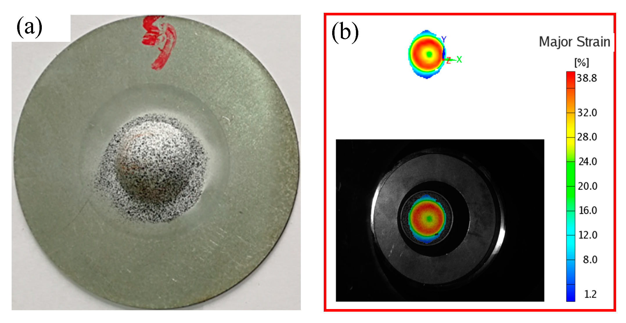
3. Hemispherical Part Drawing Experiment

The hemispherical part drawing model is used for finite element analysis, as shown in Figure 8. The diameter and the thickness of the steel sheet is 100 mm and 1.2 mm, the outer diameter of the die and the blank holder are all 55 mm, the diameter of the punch is 20 mm, the inner diameter of the die and the blank holder are 20 and 27 mm respectively, and the profile radius and outer profile radius are all 0.75 mm.
In this paper, we use the BUT400® machine as the drawing experimental equipment. As shown in Figure 9, the maximum clamping force of the sample is 400 kN, the maximum stroke of the piston is 120 mm, and the working speed is 0.750 mm/min. The test sample is a hot galvanized steel sheet DP600 with a diameter of 100mm and a thickness of 1.2 mm. By monitoring the blank holder force, we observed the influence of drawing depth on the formability of galvanized sheet. Figure 10 shows four samples of the hemispherical part drawing test.
We intend eight groups of hemispherical part drawing experiments to test the drawing depth and forming force of different blank holder forces. Detailed results of the test are shown in Table 4. The experimental results show that the drawing depth and the forming force are distinct at different blank holder force, and the drawing depth increases first and then declines with the increase of the blank holder force.
Figure 11 is a tendency analysis of the results of the hemispherical part drawing experiment. With the increase of the blank holder force, the drawing depth increased slightly. However, when the blank holder force increases to a certain extent, the drawing depth tends to be stable and remains unchanged. At the beginning, the forming force increases with the increase of the blank holder force, then decreases with the increase of the blank holder force and stabilizes. The experimental results are correct and consistent with expectations.
Spray paint for speckle measurement was sprayed on the surface of the sample, and strain was calculated by GOM Argus® optical strain analysis system. Figure 12 indicates the strain measurement result of a specimen numbered #4. When the blank holder force is 115 kN, the maximum major strain at cracking time is 38.8%.

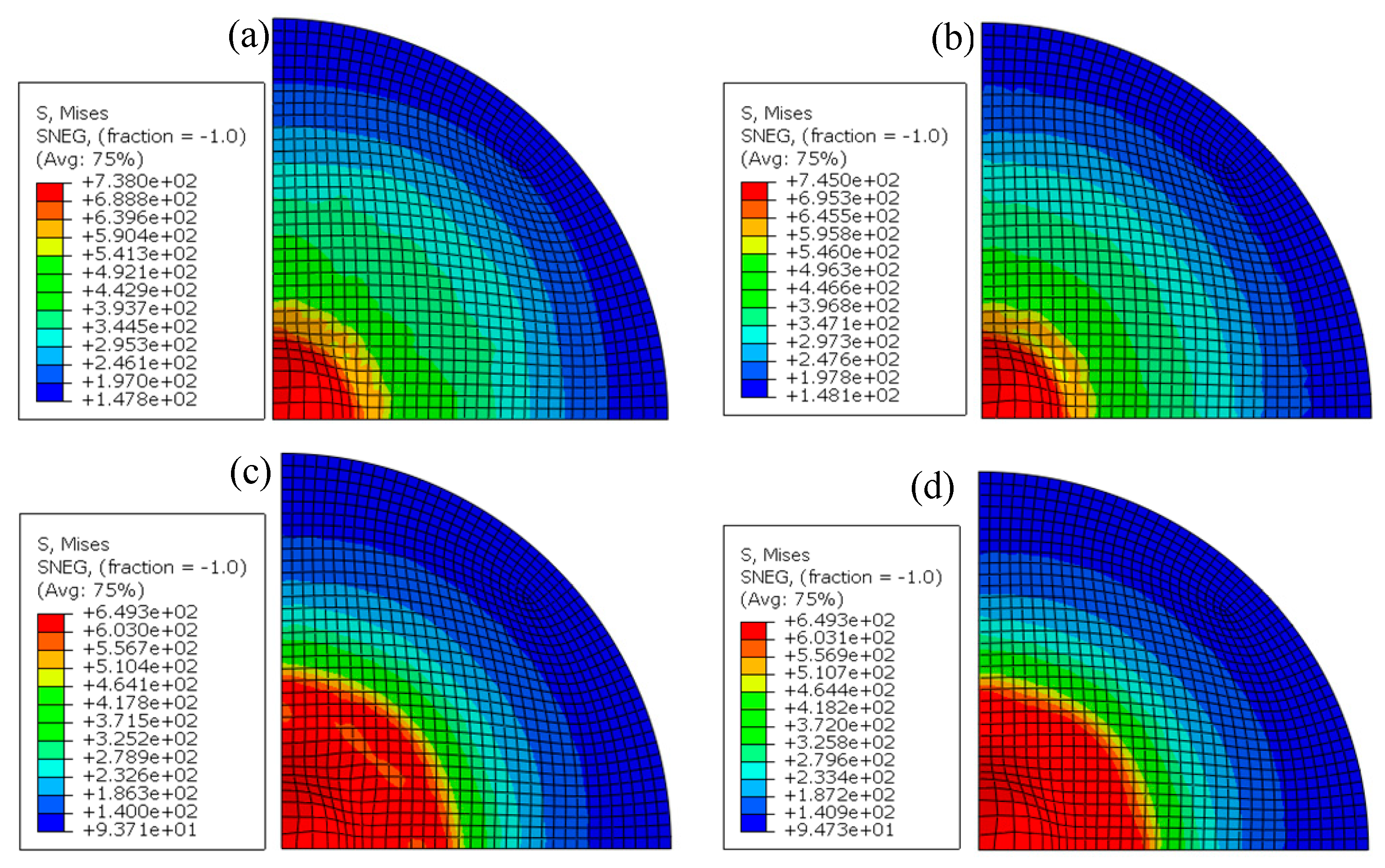
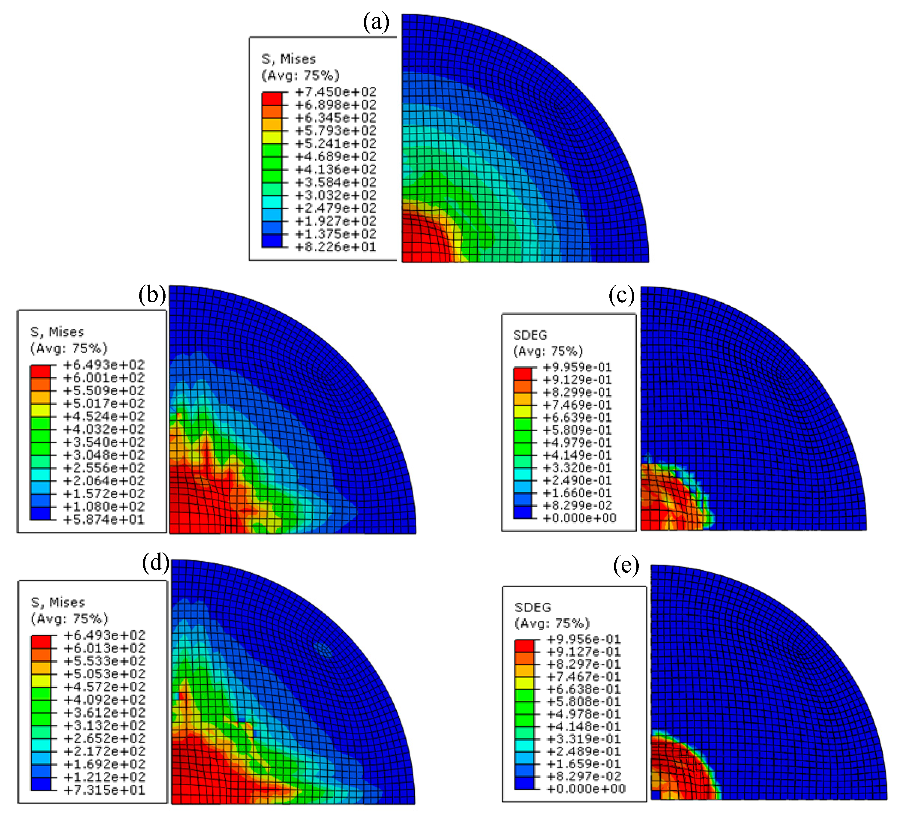
4. Damage Simulations of Zinc Coating

4.1. Damage Model Based on Cohesion Element

To explore and improve the zinc coating damage numerical simulation of galvanized steel sheet stamping, numerical simulation analysis was performed by using the blank holder force condition and the drawing depth as the stamping stroke. The zinc damage simulation of galvanized steel sheet is analyzed by establishing a finite element model considering the zinc coating. The model of finite element analysis is completely consistent with the experimental model.
Abaqus® 6.14 version software is used to carry out the finite element numerical simulation of hemispherical part drawing. To promote the efficiency of computation, the 1/4 model is adopted to analyze, and it adds symmetric constraints to the nodes on the X axis and the Y axis, as shown in Figure 13a. The final finite element analysis model is presented in Figure 13c. Three models are used to describe the material structure of galvanized steel sheet, as illustrated in Figure 13b. The element type of sheet metal is a solid element. The first model (Finite element model I, single-layer model) is to analyze the coating and substrate as a unified material, and the mechanical parameters are the data of uniaxial tension of galvanized steel sheet. The second (Finite element model II, three-layers model) and third (Finite element model III, five-layers model) models consider the substrate and the coating as two materials. Among them, the mechanical parameters of the substrate are the uniaxial tensile data for removing the zinc coating, but the mechanical parameters of the zinc coating are obtained by the Nano-indentation test and calculation. The adhesion between the coatings and the substrate of the second model are constrained by tie binding. Stiffness data transfer is equivalent to the rigid connection of the two binding surfaces and the binding area serves the absence of relative movement and deformation while the stiffness is large. However, in the third model, a further cohesive element is brought in between the coating and the substrate which is a zero-thickness element layer applied to simulate the generation and expansion of the crack in the binding layer. In the cohesive element model, the cracking of the coating is determined based on the maximum principal stress criterion, and the damage evolution process of the crack is conducted based on the interface binding energy.
Equation (12) shows the constitutive equation for the finite analysis of the zinc coating, and it shows the interfacial binding parameters between the coating and the substrate in Table 3. Three kinds of finite element model are used to simulate the hemispherical part drawing process of nine groups of different blank holder force and drawing depth. The detailed setting parameters are shown in Table 4. Stroke in numerical simulation is controlled by punch stroke, that is, the drawing depth. The total number of numerical simulations for the hemispherical part drawing is 27 times.

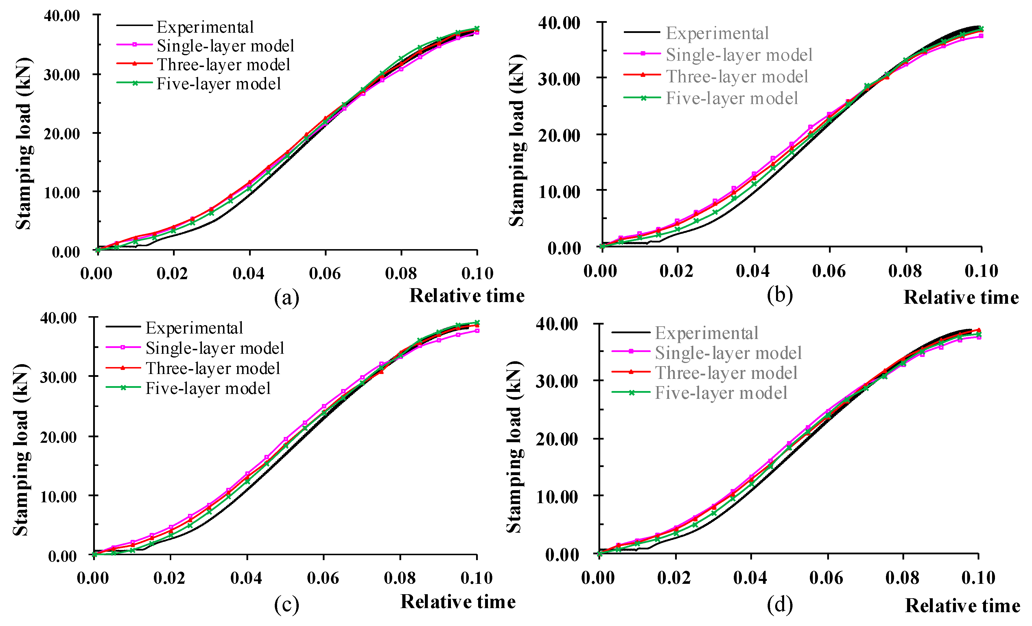
4.2. Simulation Results and Discussions

The numerical simulation results are analyzed and compared with the experimental results. Figure 14 is the numerical simulation result of hemispherical part drawing of the single-layer model and the three-layers model (binding) when blank holder force is 50 kN and punch stroke is 9.76 mm. The results show that the maximum Mises stress of the substrate is 7 MPa larger than that of the single-layer model. Mises stress distribution in the upper and lower surfaces is basically the same, with only a slight difference. However, their maximum Mises stress is nearly 100 MPa smaller than that of the substrate in the three-layers model.
Figure 15 shows results from the numerical simulation of the five-layers model under blank holder force 50 kN and punch stroke 9.76 mm, which has two 0-thickness cohesive elements to describe the linkage between the coating and the substrate. Figure 15a is the stress distribution simulation result of substrate, which is similar to the simulation result of the three-layers model. Comparing Figure 14c and Figure 15b with Figure 14d and Figure 15d, it is shown that although the maximum stress of the coating layers on the upper and lower surfaces is the same as that of the three-layers model, the stress distribution is quite different. Figure 15c,e are the simulated results of the degradation of upper and lower 0-thickness cohesive layers. The damage coefficient scalar stiffness degradation (SDEG) in almost all deformation zones is 1.0, indicating that the cohesive element has completely degenerated under the action of biaxial tensile stress. It can be concluded that the galvanized coating layers and the substrate have been disconnected. Figure 16a shows the simulation effect of the separation of the zinc coating from the steel substrate. Under the action of tension, the interface cracks gradually, the damage coefficient “SDEG” is different, and interface cracks are different, especially galvanized layer cracks most seriously at the corner of the die and the top of the punch. As shown in Figure 16b, when the simulation time is between (0.05, 0.06), the cohesion element begins to damage, and gradually cracks with the increase of stress. When the simulation time is about 0.08, the cohesion element layer is almost completely damaged, and obvious cracking occurs between the zinc coating and the steel substrate. Therefore, the substrate and the coating layers are not completely binding in the drawing process. Once the galvanized layer is detached from the substrate, owing to its tiny thickness scale, it will be powdered under the dual action of friction and stress. The results of pulverization will further affect the formability and surface quality of sheet metal by friction. Therefore, the influence of the galvanizing layer on forming performance is a dynamic process. If it is necessary to simulate the formability more accurately, it is necessary to change the friction coefficient dynamically according to the degeneration of the cohesive element.
According to the above analysis results, the stress and strain between different models cannot be further compared because of different layers of the finite element models. Therefore, this paper focuses on comparing the accuracy of numerical simulation of different models by forming force. Figure 17 shows the comparison between the forming force of different numerical simulation models and experimental under four groups of different blank holder force and stroke. In the first half of the drawing, the numerical simulation results are larger than the experimental results, and the deviation is larger. However, with the drawing process of the latter half stroke, the numerical simulation value is smaller than that of experimental value, and the deviation between the two is decreasing. Moreover, 4 sets of results in Figure 16 show the same trend. However, on the whole, the deviation between the numerical simulation of a five-layer model and the experimental results is the smallest. Therefore, the results show that the forming force of the five-layer model is closer to the experimental results, and the numerical simulation accuracy is the highest. Comparatively, the accuracy of the single-layer model is the worst, while that of the three-layers model is in the middle.
It can be observed on the above evaluation that although the forming force of the five-layers model is the closest to the experimental results, there is still some deviation from the experimental value. Especially in the beginning of the 2/3 stamping stroke, the difference is more significant. Therefore, the accuracy of numerical simulation needs to be further improved. Depending on the above analysis, friction may be a meaningful factor affecting the forming force. Especially under the condition of high strength and pressure, the powdering effect of the coating will be more obvious. However, the effect of the powdering of the zinc coating on friction has not been systematically studied. The next step of the paper is commensurate to study the dynamic friction in the stamping process of advanced high strength galvanized steel sheet.
In order to further analyze the accuracy of numerical simulation of different finite element models, the maximum forming force was extracted and compared with the experimental results, as shown in Figure 18. Table 5 is the accuracy analysis of the numerical simulation results of the maximum forming force. The average deviation of the maximum forming force of single-layer model, three-layers model and five-layer model is 2.979%, 1.173%, and 0.645%, respectively. The results of the maximum forming force are consistent with the previous analysis, and the five-layers model is the closest to the experimental results and the highest accuracy. Moreover, the variation of the maximum forming force under the different blank holder force of the three models is consistent with the experimental results. This demonstrates that the three finite element models established in this paper can simulate the stamping process of hemispherical part drawing successfully. The material parameters obtained in the experiment and the constitutive model constructed in this paper can accurately describe the mechanical deformation behavior of galvanized steel sheet, which proves the feasibility and accuracy of the above research.
In conclusion, interfacial binding energy is one of the important micro-mechanical properties of the zinc coating, which determines the forming quality, damage and service life of the coating steel sheet. In this paper, interfacial binding energy between zinc coating and substrate was achieved by the scratch test and related models, and applied to the numerical simulation of a hemispherical part drawing experiment to predict the damage evolution process of the coating. However, the experimental samples are directly from factories, and the surface morphology of the sample substrate changes greatly. The interface between the coating and the substrate is a state of staggering convexity and concavity, and the thickness distribution of the coating is nonuniform, which leads to the inaccuracy of the scratch test results. Therefore, the interface binding energy of galvanized sheet still needs to be further studied in the later stage of work.
In addition, because the fracture energy of the galvanized coating is difficult to obtain, and the sample size is large, the preset crack location is difficult to set, so the XFEM method is not used to investigate the powdering of the galvanized coating. Therefore, in order to further improve the accuracy of the finite element numerical model, it is necessary to conduct in-depth research based on the cohesion element model.

5. Conclusions

In this paper, the hot dip galvanized high strength steel DP600 is chosen as the research object. We studied mechanical behavior and its damage with the steel substrate. The experimental and numerical results show that the constitutive model can accurately describe the plastic deformation behavior of the coating, and the finite element model of the hemispherical part drawing has a high accuracy of damage numerical simulation. The main conclusions of this study are as follows:
  • The effect of the zinc coating on the formability of galvanized steel cannot be ignored. In this paper, we studied the zinc coating and its mechanical properties. The constitutive model of zinc coating based on Nano-indentation experiment and numerical model was proposed, and the constitutive model can accurately describe the plastic mechanical behavior of zinc coating.
  • The interface binding energy is an important index to reflect the zinc coating quality, and also a critical criterion to evaluate the coating damage. Based on the nano-scratch test and Griffith’s energy theory, the interface binding strength between the coating and the substrate was obtained, which can be invoked as a criterion for the detachment between the galvanized layer and steel substrate. This provides a theoretical basis for the damage of the zinc coating in the stamping process.
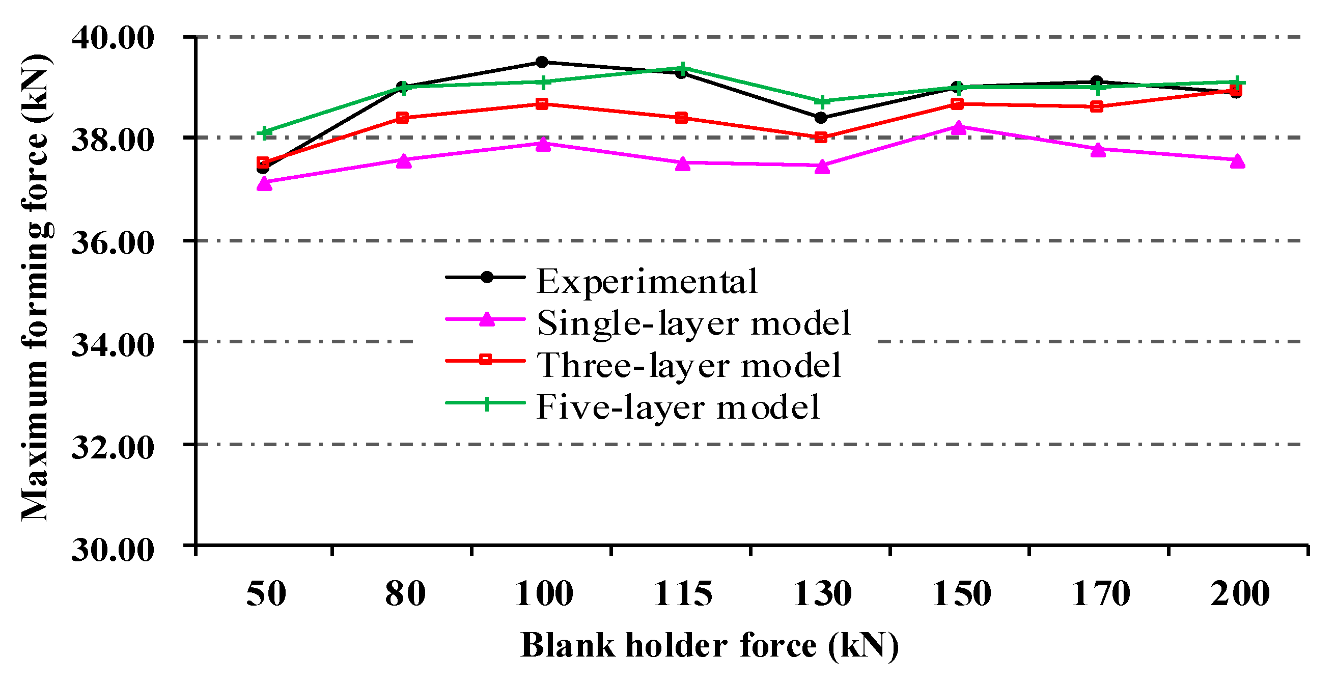
  • The damage evolution of the binding between the zinc coating and the substrate was simulated by introducing a cohesive element with 0 thickness. It can simulate the detached and damage evolution of zinc coating from the substrate accurately. Compared with other multi-layer finite element models, it has improved the accuracy of the numerical simulation of stamping through the comparative analysis of the forming force history and the maximum forming force with the experimental results.
The constitutive model, interface binding energy and damage finite element model achieved in this paper can improve the numerical simulation accuracy of galvanized steel sheet stamping to a certain extent. But there is still some deviation from the experimental results. According to the analysis, this may be caused by the great change of interfacial friction after the zinc coating is damaged and detached from the steel substrate. Therefore, further studies will consider the dynamic friction model after coating damaging, and further improve the numerical simulation accuracy of advanced high strength galvanized steel sheet.

Author Contributions

Conceptualization, G.L.; methodology, G.L. and X.L.; validation, X.L.; investigation, G.L.; resources, G.L. and X.L.; data curation, G.L.; writing—original draft preparation, G.L.; writing—review and editing, G.L.; project administration, G.L.; funding acquisition, G.L. All authors have read and agreed to the published version of the manuscript.

Funding

This research was funded by National Natural Science Foundation of China (grant No. 51505348) and open Research Fund of the State Key Laboratory of Material Processing and Die & Mould Technology (Huazhong University of Science and Technology) (grant No. P2020-019).

Acknowledgments

We express our thanks to the Wuhan branch of Baosteel Central Research Institute (R&D Center of Wuhan Iron & Steel Co., Ltd.) for their great supports for the experiment.

Conflicts of Interest

The authors declare that they have no conflict of interest.

References

  1. Anderson, D.; Winkler, S.; Bardelcik, A.; Worswick, M.J. Influence of stress triaxiality and strain rate on the failure behavior of a dual-phase DP780 steel. Mater. Des. 2014, 60, 198–207. [Google Scholar] [CrossRef]
  2. Shibli, S.M.A.; Meena, B.N.; Remya, R. A review on recent approaches in the field of hot dip zinc galvanizing process. Surf. Coat. Technol. 2015, 262, 210–215. [Google Scholar] [CrossRef]
  3. Parisot, R.; Forest, S.; Pineau, A.; Grillon, F.; Demonet, X.; Mataigne, J.M. Deformation and damage mechanisms of zinc coatings on hot-dip galvanized steel sheets: Part I. Deformation modes. Metall. Mater. Trans. A 2004, 35, 797–811. [Google Scholar] [CrossRef]
  4. Shen, Z.; Ding, Y.; Chen, J.; Amirkhiz, B.S.; Wen, J.Z.; Fu, L.; Gerlich, A.P. Interfacial bonding mechanism in Al/coated steel dissimilar refill friction stir spot welds. J. Mater. Sci. Technol. 2019, 35, 1027–1038. [Google Scholar] [CrossRef]
  5. Tokunaga, T.; Ohno, M.; Matsuura, K. Coatings on Mg alloys and their mechanical properties: A review. J. Mater. Sci. Technol. 2018, 34, 1119–1126. [Google Scholar] [CrossRef]
  6. Wang, X.; Wei, L.; Zhao, J.; Cheng, H.; Wang, X.; Liu, Y.; Hao, Y. Research on dynamic mechanical behavior and damage of steel structure galvanized coating. In Proceedings of the International Conference on Smart City & Systems Engineering, Changsha, China, 11–12 November 2017; pp. 244–247. [Google Scholar] [CrossRef]
  7. Pinger, T.; Rückriem, E.-M. Investigation on the corrosion and mechanical behavior of thin film batch galvanized thick plate components in clinch joints. Int. J. Adv. Manuf. Technol. 2015, 86, 29–36. [Google Scholar] [CrossRef]
  8. Cora, Ö.N.; Ağcayazı, A.; Namiki, K.; Sofuoğlu, H.; Koç, M. Die wear in stamping of advanced high strength steels-Investigations on the effects of substrate material and hard-coatings. Tribol. Int. 2012, 52, 50–60. [Google Scholar] [CrossRef]
  9. Wang, W.; Wang, K.; Zhao, Y.; Hua, M.; Wei, X. A study on galling initiation in friction coupling stretch bending with advanced high strength hot-dip galvanized sheet. Wear 2015, 328–329, 286–294. [Google Scholar] [CrossRef]
  10. Vourlias, G.; Pistofidis, N.; Stergioudis, G.; Tsipas, D. The effect of alloying elements on the crystallization behaviour and on the properties of galvanized coatings. Cryst. Res. Technol. 2004, 39, 23–29. [Google Scholar] [CrossRef]
  11. Zhong, N.; Zhang, K.; Li, J.; Hu, W.B. Improvement of the galvanized coating quality of high strength dual phase steels by pre-electroplating nickel layer. Steel Res. Int. 2011, 82, 180–186. [Google Scholar] [CrossRef]
  12. Parisot, R.; Forest, S.; Pineau, A.; Grillon, F.; Demonet, X.; Mataigne, J.M. Deformation and damage mechanisms of zinc coatings on hot-dip galvanized steel sheets: Part II. Damage modes. Metall. Mater. Trans. A 2004, 35, 813–823. [Google Scholar] [CrossRef]
  13. Di Cocco, V.; Iacoviello, F.; D’Agostino, L.; Natali, S. Damage micromechanisms in a hot dip galvanized steel. Procedia Struct. Integr. 2017, 3, 231–236. [Google Scholar] [CrossRef]
  14. Petit, E.J.; Grosbety, Y.; Aden-Ali, S.; Gilgert, J.; Azari, Z. Microstructure of the coating and mechanical properties of galvanized chromium-rich martensitic steel. Surf. Coat. Technol. 2010, 205, 2404–2411. [Google Scholar] [CrossRef]
  15. Yu, Z.Q.; Hou, Y.K.; Li, S.H.; Lin, Z.Q.; Zhang, W.G. Surface damage behavior of galvanized steel sheets in forming process under tension-bending. Int. J. Mod. Phys. B 2010, 24, 5877–5884. [Google Scholar] [CrossRef]
  16. Xu, C.; Lin, Z.Q.; Li, S.H.; Zhang, W.G. Research on shear strength of galvannealed coatings. Mater. Des. 2007, 28, 1668–1671. [Google Scholar] [CrossRef]
  17. Song, G.-M.; Sloof, W.G. Characterization of the failure behavior of zinc coating on dual phase steel under tensile deformation. Mat. Sci. Eng. A Struct. 2011, 528, 6432–6437. [Google Scholar] [CrossRef]
  18. Chang, S.-H.; Heo, Y.-M. Study on characteristics of the warm deep drawability and simulation for the galvannealed steel sheet. Adv. Sci. Lett. 2013, 19, 3697–3702. [Google Scholar] [CrossRef]
  19. He, Q.Z.; Hu, H.; Belouettar, S.; Guinta, G.; Yu, K.; Liu, Y.; Biscani, F.; Carrera, E.; Potier-Ferry, M. Multi-scale modelling of sandwich structures using hierarchical kinematics. Compos. Struct. 2011, 93, 2375–2383. [Google Scholar] [CrossRef]
  20. Behrens, B.A.; Vucetic, M.; Neumann, A.; Osiecki, T.; Grbic, N. Experimental test and FEA of a sheet metal forming process of composite material and steel foil in sandwich design using LS-DYNA. In Proceedings of the 18th International ESAFORM Conference on Material Forming, ESAFORM 2015, Graz, Austria, 15–17 April 2015; Trans Tech Publications Ltd.: Graz, Austria, 2015; pp. 439–445. [Google Scholar] [CrossRef]
  21. Rajabi, A.; Kadkhodayan, M.; Manoochehri, M.; Farjadfar, R. Deep-drawing of thermoplastic metal-composite structures: Experimental investigations, statistical analyses and finite element modeling. J. Mater. Process. Technol. 2015, 215, 159–170. [Google Scholar] [CrossRef]
  22. Shiri, S.; Naceur, H.; Roelandt, J.M. Numerical modelling of sheet metal forming and crashworthiness of laminated steel structures using multi-layered solid-shell elements. Eur. J. Comput. Mech. 2012, 21, 351–364. [Google Scholar] [CrossRef]
  23. Parsa, M.H.; Mohammadi, S.V.; Aghchai, A.J. Al3105/polypropylene/Al3105 laminates springback in V-die bending. Int. J. Adv. Manuf. Technol. 2014, 75, 849–860. [Google Scholar] [CrossRef]
  24. Parsa, M.H.; ahkami SNa Ettehad, M. Experimental and finite element study on the spring back of double curved aluminum/polypropylene/aluminum sandwich sheet. Mater. Des. 2010, 31, 4174–4183. [Google Scholar] [CrossRef]
  25. Li, C.; Chi, C.; Lin, P.; Zhang, H.; Liang, W. Deformation behavior and interface microstructure evolution of Al/Mg/Al multilayer composite sheets during deep drawing. Mater. Des. 2015, 77, 15–24. [Google Scholar] [CrossRef]
  26. Parisotab, R.; Foresta, S.; Gourguesa, A.-F.; Pineaua, A.; Mareuseb, D. Modeling the mechanical behavior of a multicrystalline zinc coating on a hot-dip galvanized steel sheet. Comp. Mater. Sci. 2000, 19, 189–204. [Google Scholar] [CrossRef]
  27. Ucun, İ.; Aslantas, K. Numerical simulation of orthogonal machining process using multilayer and single-layer coated tools. Int. J. Adv. Manuf. Technol. 2011, 54, 899–910. [Google Scholar] [CrossRef]
  28. Lee, S.; Joun, M.; Kim, D.; Lee, J. Effect of elastic-plastic behavior of coating layer on drawability and frictional characteristic of galvannealed steel sheets. J. Mech. Sci. Technol. 2016, 30, 3313–3319. [Google Scholar] [CrossRef]
  29. Kim, S.I.; Her, J.U.; Jang, Y.C.; Lee, Y. Experimental and finite element analysis for fracture of coating layer of galvannealed steel sheet. Trans. Nonferr. Metal. Soc. 2011, 21, s111–s116. [Google Scholar] [CrossRef]
  30. Bettaieb, A.B.; Tuninetti, V.; Duchene, L. Numerical simulation of T-bend of multilayer coated metal sheet using solid-shell element. In Proceedings of the 14th International Conference on Metal Forming, Metal Forming 2012, Krakow, Poland, 16–19 September 2012; Wiley-VCH Verlag: Krakow, Poland, 2012; pp. 1311–1314. [Google Scholar]
  31. Oliver, W.C.; Pharr, G.M. An improved technique for determining hardness and elastic modulus using load and displacement sensing indentation experiments. J. Mater. Res. 1992, 7, 1564–1583. [Google Scholar] [CrossRef]
  32. Park, H.S.; Kwon, D. An energy approach to quantification of adhesion strength from critical loads in scratch tests. Thin Solid Film. 1997, 307, 156–162. [Google Scholar] [CrossRef]
  33. Griffith, A.A. The phenomena of rupture and flow in solids. Philos. Trans. R. Soc. Lond. 1921, 221, 163–198. [Google Scholar] [CrossRef] [Green Version]
Figure 1. Cross-section microstructure of galvanized steel sheet DP600.
Coatings 10 00202 g001
Figure 2. Measurement results of surface morphology: (a) Original steel sheet with zinc coating, (b) Steel sheet after acid pickling without zinc coating.
Coatings 10 00202 g002
Figure 3. Nano-indentation model: (a) Load-displacement curve, (b) Cross section of Nano-indentation.
Coatings 10 00202 g003
Figure 4. Test results of loading and unloading curves of Nano-indentation.
Coatings 10 00202 g004
Figure 5. Mechanical behavior of zinc coating: (a) Stress-strain curve, (b) Comparison of the results of the indentation curve between numerical simulation and test.
Coatings 10 00202 g005
Figure 6. Process and result of scratch test: (a) Loading process of scratch test, (b) Scratch morphology.
Coatings 10 00202 g006
Figure 7. The change of tangential load Fx, friction coefficient μ and acoustic signal AE with time t.
Coatings 10 00202 g007
Figure 8. Hemispherical part drawing model (mm): 1. Sheet thickness, 2. Sheet diameter, 3. Die diameter, 4. Blank holder diameter, 5. Die outer diameter, 6. Outer diameter of the blank holder, 7. Profile radius of the Die, 8. Outer profile radius of the die, 9. Outer profile radius of the blank holder, 10. Profile radius of the blank holder, 11. Die thickness, 12. Blank holder thickness, 13. Punch diameter, 14. Drawing depth.
Coatings 10 00202 g008
Figure 9. Hemispherical part drawing test device: (a) BUT400 drawing machine, (b) hemispherical part drawing die, (c) Lower die of hemispherical part drawing die.
Coatings 10 00202 g009
Figure 10. Part samples of hemispherical part drawing test under different blank holder force: (a) Sample of 50 kN test, (b) Sample of 80 kN test, (c) Sample of 130 kN test, (d) Sample of 200 kN test.
Coatings 10 00202 g010
Figure 11. Data analysis on the tests of hemispherical part drawing.
Coatings 10 00202 g011
Figure 12. Strain measurement after white light scanning (blank holder force is 115 kN): (a) White light scanning sample, (b) Measurement results of major strain.
Coatings 10 00202 g012
Figure 13. Preprocessing model of finite element analysis: (a) 1/4 symmetry constraints of sheet material, (b) Assumption of finite element model for layered structure of galvanized steel sheet, (c) Finite element assembly models.
Coatings 10 00202 g013aCoatings 10 00202 g013b
Figure 14. Numerical simulation results of the hemispherical part drawing under the blank holder force of 50 kN and the punch stroke of 9.76 mm: (a) Single-layer model, (b) Substrate of the three-layers model (Binding), (c) Upper coating layer (Contact with the die) of the three-layers model (Binding), (d) Lower coating layer (Contact with the blank holder and punch) of the three-layers model (Binding).
Coatings 10 00202 g014
Figure 15. Numerical simulation results of the drawing of the five-layers model under blank holder force 50 kN and punch stroke 9.76 mm: (a) Substrate, (b) Upper coating layer (contact with the die), (c) Upper cohesive layer, (d) Lower coating layer (contact with the blank holder and punch), (e) Lower cohesive layer.
Coatings 10 00202 g015
Figure 16. Failure of cohesion element under blank holder force 50 kN: (a) Damage of zinc coating layers, (b) Damage of zinc coating layers with drawing time.
Coatings 10 00202 g016
Figure 17. Stamping force history comparative between numerical simulation results of different element models and experimental results: (a) Blank holder force 50 kN, punch stroke 9.76 mm, (b) Blank holder force 115 kN, punch stroke 10.25 mm, (c) Blank holder force 170 kN, punch stroke 10.75 mm, (d) Blank holder force 200 kN, punch stroke 10.45 mm.
Coatings 10 00202 g017
Figure 18. Comparison between numerical simulation results of maximum forming force and experimental results.
Coatings 10 00202 g018
Table 1. Detailed results of uniaxial tensile tests.
Steel SheetDirection of the SampleYield Strength σs (MPa)Tensile Strength σb (MPa)Elongation δNormal Anisotropy rHardening Index n
Steel sheet with zinc coatingR0039460927.1%1.1710.168
R4538860924.8%0.940.176
R9037760825.5%0.8530.181
Steel sheet without zinc coatingR0039662124.4%1.1240.173
R4539660825.1%1.0230.17
R9038760125.3%0.9020.175
Table 2. Related parameters of Nano-indentation test.
ParameterSymbolDimension
Indentation load[F]LMT−2
Yield strength[σy]L−1MT−2
Hardening index[n]1
Elastic modulus[Ef]L−1MT−2
Indentation depth[h], [hf]L
Table 3. Interface binding energy of the interface between zinc coating and substrate.
Critical Load
(N)
Critical Friction
Coefficient
Contact Radius
(μm)
Elastic Modulus (GPa)
Substrate/Coating
Poisson Ratio
Substrate/Coating
Binding Energy
(× 103 J/m2)
15.760.20221.72210/1350.3/0.30.2022
Table 4. Detailed test results of the hemispherical part drawing process.
Test Group#1#2#3#4#5#6#7#8
Blank holder force/kN5080100115130150170200
Drawing depth/mm9.7610.0910.1710.2510.2510.5410.7510.45
Max. forming force/kN37.3838.9739.4839.2538.3938.9939.1338.89
Table 5. Accuracy analysis of the finite element simulation of the maximum forming force.
Blank Holder Force
(kN)
Experimental
(kN)
Single-LayerThree-LayersFive-Layers
Simulation
(kN)
Relative DeviationSimulation
(kN)
Relative DeviationSimulation
(kN)
Relative Deviation
5037.3837.140.637%37.510.344%38.101.926%
8038.9737.593.541%38.381.505%39.010.103%
10039.4837.884.054%38.652.107%39.100.963%
11539.2537.504.455%38.402.168%39.380.331%
13038.3937.482.370%38.001.006%38.710.834%
15038.9938.241.918%38.670.810%39.020.077%
17039.1337.803.404%38.611.333%39.010.307%
20038.8937.553.452%38.930.114%39.130.617%
Average deviation 2.979% 1.173% 0.645%

