Article

The Structure, Morphology, and Mechanical Properties of Ta-Hf-C Coatings Deposited by Pulsed Direct Current Reactive Magnetron Sputtering

1
ICD LASMIS: Université de Technologie de Troyes, Antenne de Nogent, Pôle Technologique de Haute-Champagne, 52800 Nogent, France
2
Nogent International Center for CVD Innovation, LRC CEA-ICD LASMIS, UT.T, Antenne de Nogent-52, Pôle Technologique de Haute-Champagne, 52800 Nogent, France
3
Institut FEMTO-ST: CNRS, UTBM, Univ. Bourgogne Franche-Comté, Site de Montbéliard, F-90010 Belfort Cedex, France
4
Université Paris Est: ICMPE (UMR 7182), CNRS, UPEC, 2-8 rue Henri Dunant, 94320 Thiais, France
5
Institut Jean Lamour (UMR CNRS 7198), Université de Lorraine, 54000 Nancy, France
*
Author to whom correspondence should be addressed.
Coatings 2020, 10(3), 212; https://doi.org/10.3390/coatings10030212
Submission received: 31 January 2020 / Revised: 25 February 2020 / Accepted: 27 February 2020 / Published: 28 February 2020
(This article belongs to the Special Issue Magnetron Sputtering Deposited Thin Films and Its Applications)

Abstract

:
Ta, Hf, TaCx, HfCx, and TaxHf1-xCy coatings were deposited by reactive pulsed Direct Current (DC) magnetron sputtering of Ta or Hf pure metallic targets in Ar plus CH4 gas mixtures. The properties have been investigated as a function of the carbon content, which is tuned via the CH4 flow rate. The discharge was characterized by means of Optical Emission Spectroscopy and, in our conditions, both Ta-C and Hf-C systems seem to be weakly reactive. The structure of the as-deposited pure tantalum film is metastable tetragonal β-Ta. The fcc-MeCx carbide phases (Me = Ta or Hf) are {111} textured at low carbon concentrations and then lose their preferred orientation for higher carbon concentrations. Transmission Electron Microscopy (TEM) analysis has highlighted the presence of an amorphous phase at higher carbon concentrations. When the carbon content increases, the coating’s morphology is first compact-columnar and becomes glassy because of the nano-sized grains and then returns to an open columnar morphology for the higher carbon concentrations. The hardness and Young’s modulus of TaCx coatings reach 36 and 405 GPa, respectively. For HfCx coatings, these values are 29 and 318 GPa. The MeCx coating residual stresses increase with the addition of carbon (from one-hundredth of 1 MPa to 1.5 GPa approximately). Nevertheless, the columnar morphology at a high carbon content allows the residual stresses to decrease. Concerning TaxHf1-xCy coatings, the structure and the microstructure analyses have revealed the creation of a nanostructured coating, with the formation of an fcc superlattice. The hardness is relatively constant independently of the chemical composition (22 GPa). The residual stress was strongly reduced compared to that of binary carbides coatings, due to the rotation of substrates.

1. Introduction

Nowadays, surface treatments are widely used at industrial scale to improve the lifetime of many components or tools in many applications fields [1]. Surface functionalities can be addressed by a wide variety of methods. Mechanical treatment, such as SMAT (Surface Mechanical Attrition Treatment), can significantly enhance mechanical properties by severe plastic deformation for producing superficial ultrafine-grained alloys and metals [2]. Deposition technologies at atmospheric pressure (sol-gel, spraying based technologies, etc.) can provide the surface protection of biomedical materials to improve corrosion resistance and enhance biocompatibility [3]. Plasma spray techniques are also used for coatings in extreme environments such as thermal barrier coatings (TBCs), which are advanced ceramic coatings that are applied to metallic surfaces such as gas turbine blades and aerospace engines [4,5]. Since the 1980s, low-pressure physical or chemical vapor deposition techniques are also widely used for thin film deposition in many application fields, including antibacteria [6], anticorrosion [7,8], and hard coatings [9,10].
Ultra High Temperature Ceramics (UHTCs) offer an exceptional combination of properties as high mechanical and thermal resistances (a melting point over 3000 K) [11]. These materials can be used in various applications working in extreme conditions, such as hypersonic vehicles or solar cells [12,13,14,15]. TaC and HfC are known as the two binary carbides with the highest melting temperatures (Tm) [16]. This has recently been confirmed by Cedillos-Barraza et al., who measured melting temperatures with a laser system on bulk materials sintered by Spark Plasma Sintering (SPS); Tm(TaC) = 4041 K and Tm(HfC) = 4232 K [17,18]. Some authors have studied the synthesis of TaCx and HfCx coatings by reactive or non-reactive magnetron sputtering. However, within the Ta-Hf-C system, some ternary alloys can offer melting points beyond the HfC and TaC binary carbides.
Lasfargues et al. have deposited HfC and TaC coatings from compound targets [19]. They obtained chemical composition ranging from HfC0.66 to HfC0.76 and from TaC0.61 to TaC0.81 by tuning the substrate’s bias voltage and temperature. The authors attribute the composition variation to the enhancement of the adatom’s mobility by increasing those two parameters. All the HfC coatings exhibit a faced-centered cubic (fcc) structure with a {111} texture (which becomes random when the bias substrate increases), whereas TaC coatings (also fcc) show a small fraction of Ta2C (hcp-structured) [19]. They obtained a compact, smooth, and V-shaped columnar growth morphology for all coatings. Evans et al. have synthesized TaC/a-C:H coatings by the reactive magnetron sputtering of a pure metallic target in Ar-C2H2 gas mixtures [20,21,22]. They show that a coating’s hardness drops from 18 to 12 GPa when the fraction of the amorphous phase (a-C:H) increases [20]. A bias voltage (between −50 and −150 V) applied during the deposition favors TaC crystallization, which allows the hardness to increase from 12 to 20 GPa [21]. Vargas et al. have used CH4 as a reactive gas to synthesize TaC thin films [23]. A nanocrystallized TaC film was deposited, and the composition range was between TaC0.29 and TaC1.17.
HfC coatings can be synthesized in a reactive mode with C2H2 or CH4 [24,25]. The same effect was observed in TaC coatings; that is, the hardness decreases due to the appearance of an amorphous phase.
The aforementioned references, concerning the synthesis of TaCx and HfCx coatings by magnetron sputtering, are all that are found in the literature. Thus, there is a lack of data on the influence of both deposition parameters and carbon content on the structure, morphology, and mechanical properties of TaCx and HfCx coatings synthesized by reactive magnetron sputtering. Indeed, Jansson et al. have published an extensive review about the sputter deposition of transition metal carbide, and they strongly insist on the role of carbon content in tuning certain coating properties (such as the structure or the microstrucuture) [26]. Moreover, the correlation between the characterization of plasma species from the Ta-Ar-CH4 and Hf-Ar-CH4 discharges and the resulting coatings properties is lacking in the literature. The aim of this work is to synthesize TaCx and HfCx thin films by pulsed DC reactive magnetron sputtering, with CH4 as the reactive gas. The use of CH4 helps to provide better control of both the coating microstructure and the composition compared to C2H2, due to the lower amount of carbon brought. Indeed, if those coatings are used in applications implying a high temperature, the amorphous a-C:H phase easily formed by C2H2 limits the thermal stability. Furthermore, the relationship between the discharge characterization, the deposition parameters, and the coating’s properties was established. Only one reference was found in the literature on TaxHf1-xCy ternary alloy coatings obtained by magnetron sputtering [27]. Due to the lack of literature on TaxHf1-xCy coatings, it is necessary to control the process with binary carbides, in order to determine the experimental conditions necessary to synthesize ternary alloys. In this work, we, for the first time, synthesized TaxHf1-xCy coatings by reactive magnetron sputtering with a characterization of the structure, the microstructure, the morphology, and the mechanical properties (hardness, Young’s modulus, and residual stress).

2. Experimental Details

2.1. Deposition

Ta, TaCx, Hf, HfCx, and TaxHf1-xCy thin films were deposited by pulsed DC reactive magnetron sputtering of disc targets (200 mm in diameter) in a 100 L Alcatel vacuum chamber in pure Ar or in Ar-CH4 reactive discharges. The deposition chamber was pumped down to 10−4 Pa before each run. Substrates (Si wafers, glass slides, and M2 steel) were degreased in acetone by an ultrasonic bath and then successively rinsed by ethanol and dried with warm air. The target-to-substrate distance was 13 cm. A substrate etching was performed in pure argon before each deposition stage with biasing at -600 V for 30 min. Ta (99.9% purity) and Hf (99.9% purity) targets were also etched in pure argon at 2 A. Solvix (50 kHz) and Advanced Energy MDX pulsed DC (50 kHz) power supplies powered the substrate holder and targets, respectively. The argon flow rate (DAr) was kept constant at 30 sccm for all experiments, and the CH4 flow rate (DCH4) increased from 1 to 6 sccm for the coating’s synthesis in reactive conditions. The working pressure was 1 Pa, and the substrate holder was kept at floating potential for all experiments.
Optical Emission Spectroscopy (OES) measurements were carried out with a triple optical fiber placed at mid-distance between the target and the substrate. The Ar0, Ta0, Hf0, and H wavelengths used to calculate the I T a 0 I A r 0 , I H f 0 I A r 0 , and I H α I A r 0 ratios ((I) being the peak intensity) were 750.4, 696.9, 706.4, and 656.3 nm respectively. Experimental conditions of the Ta, TaCx, Hf, and HfCx coatings synthesized by pulsed DC reactive and non-reactive magnetron sputtering are summarized in Table 1.
Concerning TaxHf1-xCy coatings, the discharge current on each (Ta and Hf) target was tuned between 1 and 3 A by maintaining the total current dissipated on both targets at 4 A. The CH4 flow rate was 8 sccm (indeed, the pure TaC and HfC phases were obtained with 4 sccm of CH4, as shown in Section 3.2). The substrate holder rotation was set to 10 rpm. Table 2 summarizes the experimental conditions of the ternary alloy synthesis.

2.2. Characterizations

The coatings’ thickness was measured by an Altisurf 500 profilometer, and it remained between 2 and 3 µm. The coatings’ cross-sectional morphology was observed with an FEG (Field Emission Gun), Hitachi SU 8030 SEM.
X-Ray Diffraction (XRD) was performed with a Brüker D8 Advance diffractometer using Cu K radiation (= 1.54060 Å; accelerating voltage = 40 kV; current = 40 mA) in θ–2θ mode from 20° to 120° with a 0.02° step.
Young’s modulus and hardness were obtained by means of a Nano Indenter XP, MTS Systems Corporation, with a Continuous Stiffness Measurement (CSM) option. The indenter is a three-side pyramidal diamond tip (Berkovitch). The values of hardness and Young’s modulus were measured from an average of 10 indents. The depth of penetration was 200 nm.
The coating’s composition was estimated via XPS measurement by calculating T a 4 f ( T a 4 f + C 1 s ) and H f 4 f ( H f 4 f + C 1 s ) area peak ratios. Ar+ etching was performed to eliminate the surface’s contamination layer (60 s for TaCx coatings and 2 min for HfCx coatings). A resolution of 0.1 eV was used with K (Thermo) fitted with a monochromatic Al Kα X-ray source (spot size: 400 µm) and a flood gun for static charge compensation.
The transmission electron microscope (TEM) was a JEM - ARM 200F Cold FEG TEM/STEM operating at 200 kV and equipped with a spherical aberration (Cs) probe and image correctors (a point resolution of 0.12 nm in TEM mode and 0.078 nm in STEM mode).
The residual stresses are measured from an iron-substrate curvature before and after deposition, using an Altisurf profilometer. The stress was then calculated using Stoney’s equation [28], as in [29].

3. Results and Discussion

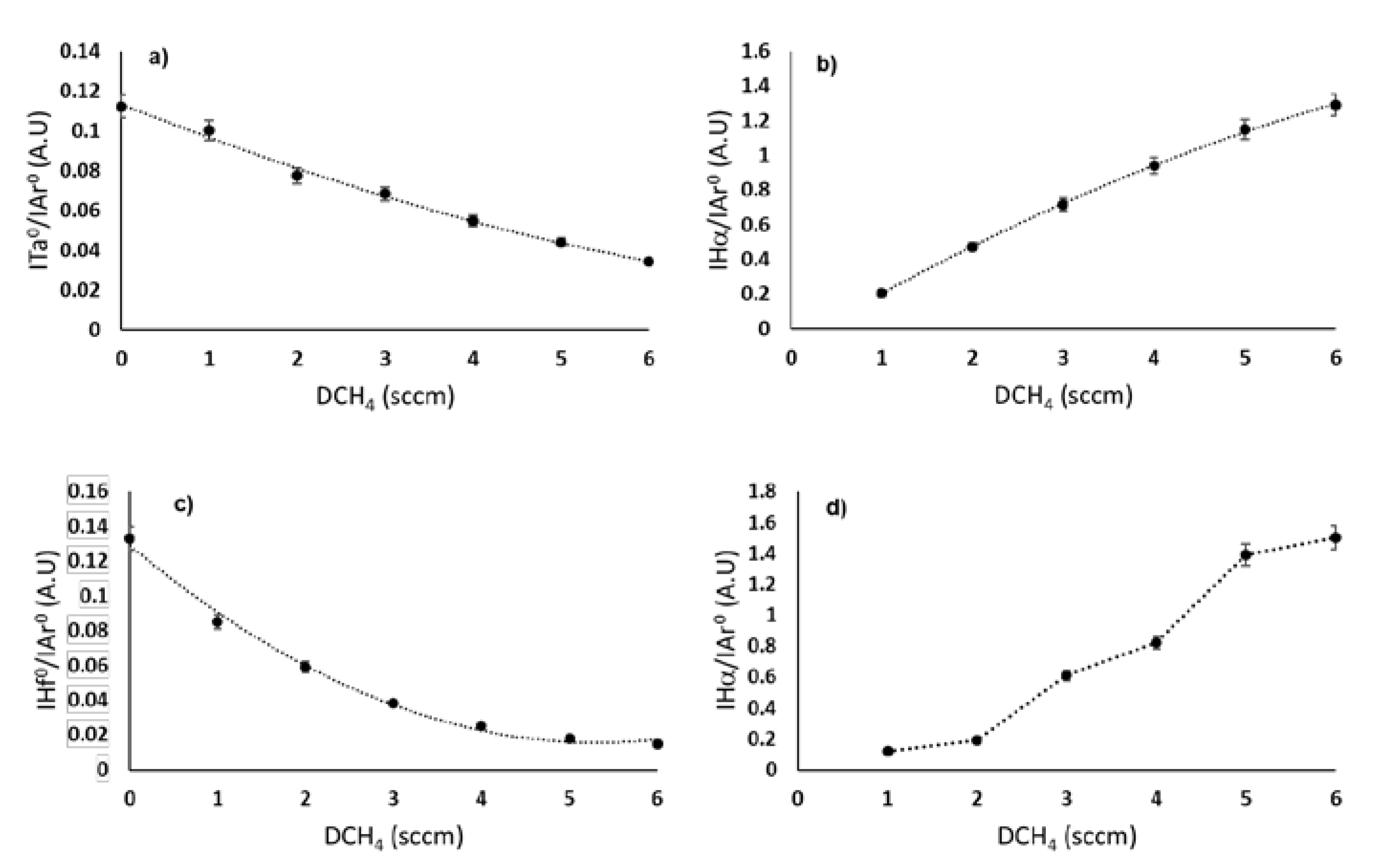
3.1. Reactive Discharge Characterization

The Ta-Ar and Hf-Ar discharges seem to have a similar behavior when the CH4 flow rate increases. A continuous decrease of I T a 0 I A r 0 (Figure 1a) and I H f 0 I A r 0 (Figure 1c) ratios was observed with an increasing C2H2 flow rate. These evolutions are due to the decrease in the metallic species density, which can first be explained by the target’s poisoning associated with the compound’s sputtering yield, which is lower than that of the metal. The decrease in the argon partial pressure when CH4 is introduced at a constant total pressure also leads to a decrease in the sputtering rate. The electronic energy was also shared between the Ar excitation/ionization and the CH4 dissociation, leading to an Ar+ rarefaction.
The I H α I A r 0   (Figure 1b,d corresponding to Ta-Ar-CH4 and Hf-Ar-CH4 discharges) ratio increases when CH4 is introduced into the chamber. This behavior is due to the increase of the H radicals concentration following the different dissociation reactions of CH4 molecules.
Figure 2 shows the evolution of the TaCx (Figure 2a) and HfCx (Figure 2b) coatings’ growth rate when the inlet CH4 flow rate increases. The growth rate drops as DCH4 increases for both TaCx and HfCx coatings (from 4 to 1.5 µm/h for TaCx and from 5 to 2 µm/h for HfCx). This is a common phenomenon due to the sputtering yield of the compound lower than that of the metal. This also confirms the target’s poisoning as seen in Figure 1. Moreover, the Ar partial pressure declines when CH4 is introduced because the total pressure is kept constant at 1 Pa. Hence, the sputtering rate decreases, which is consistent with the previous observations (Figure 1).

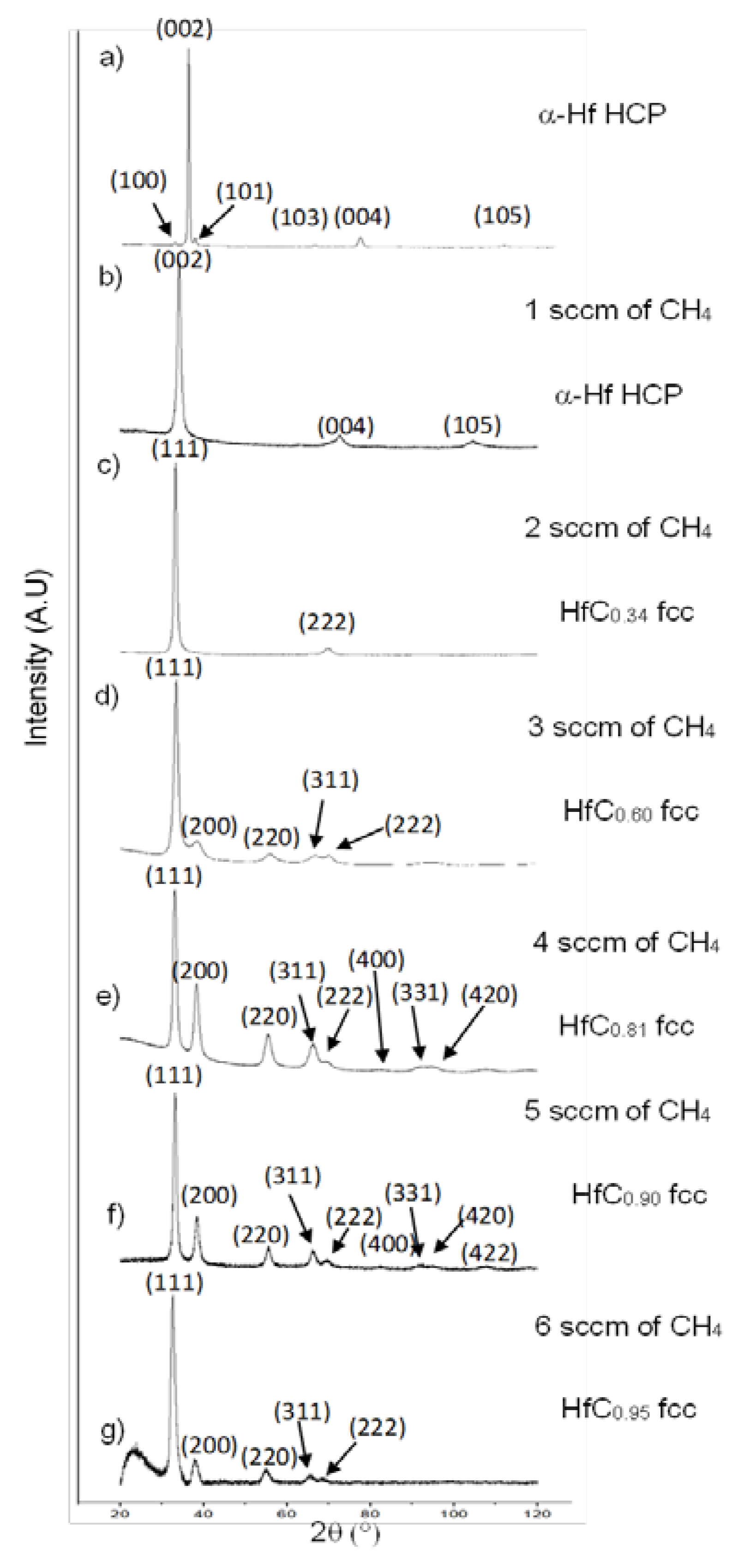
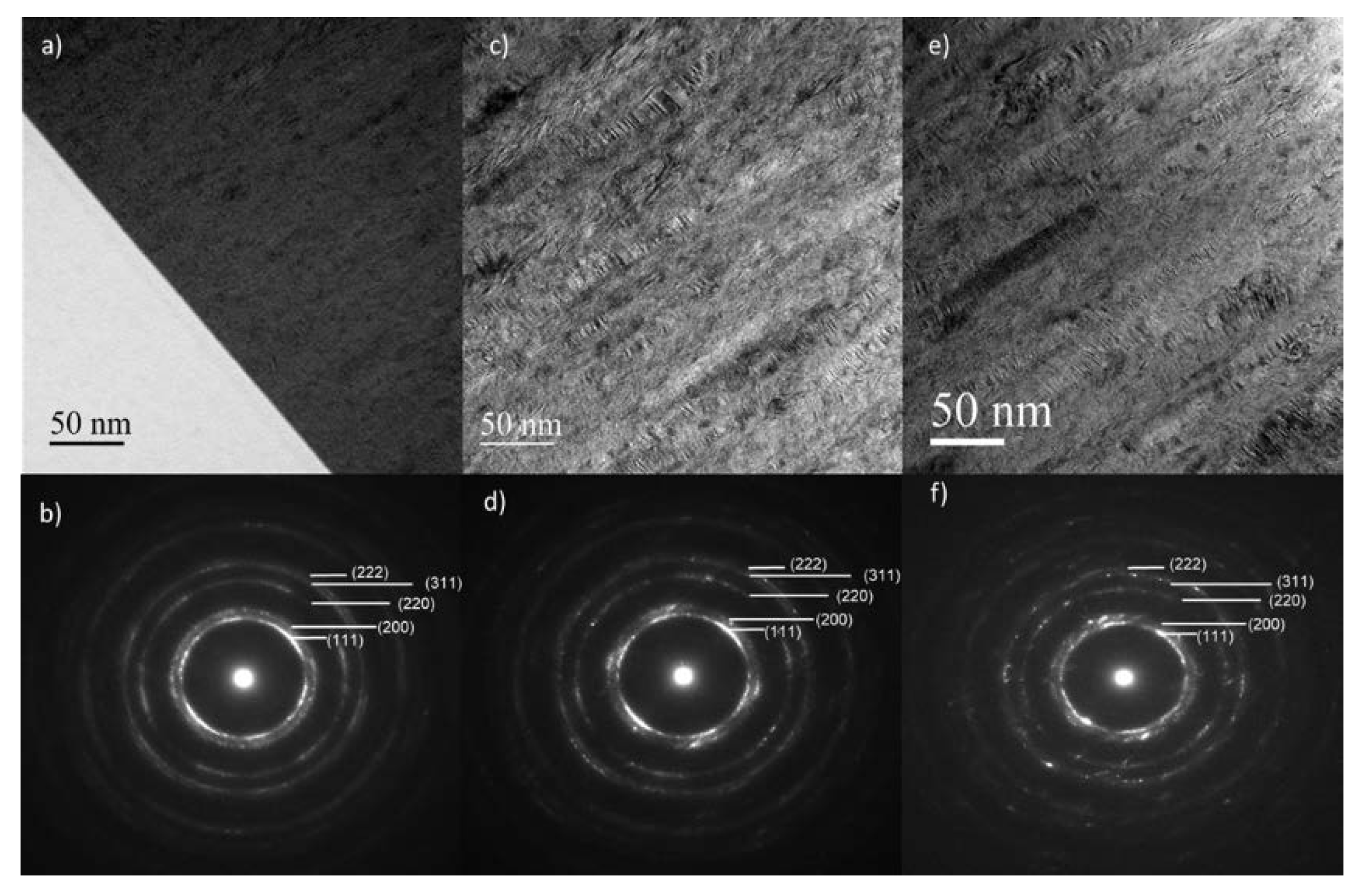
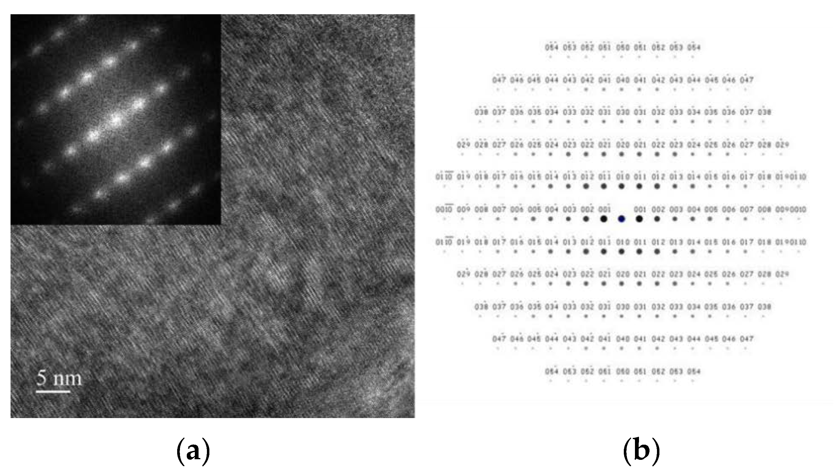
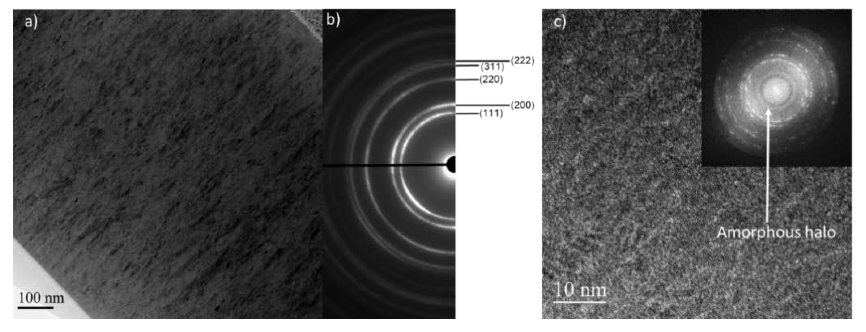
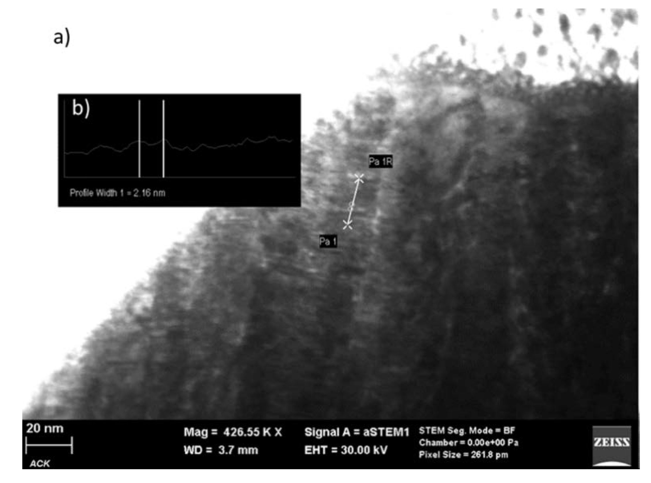
3.2. Composition, Structure, and Microstructure
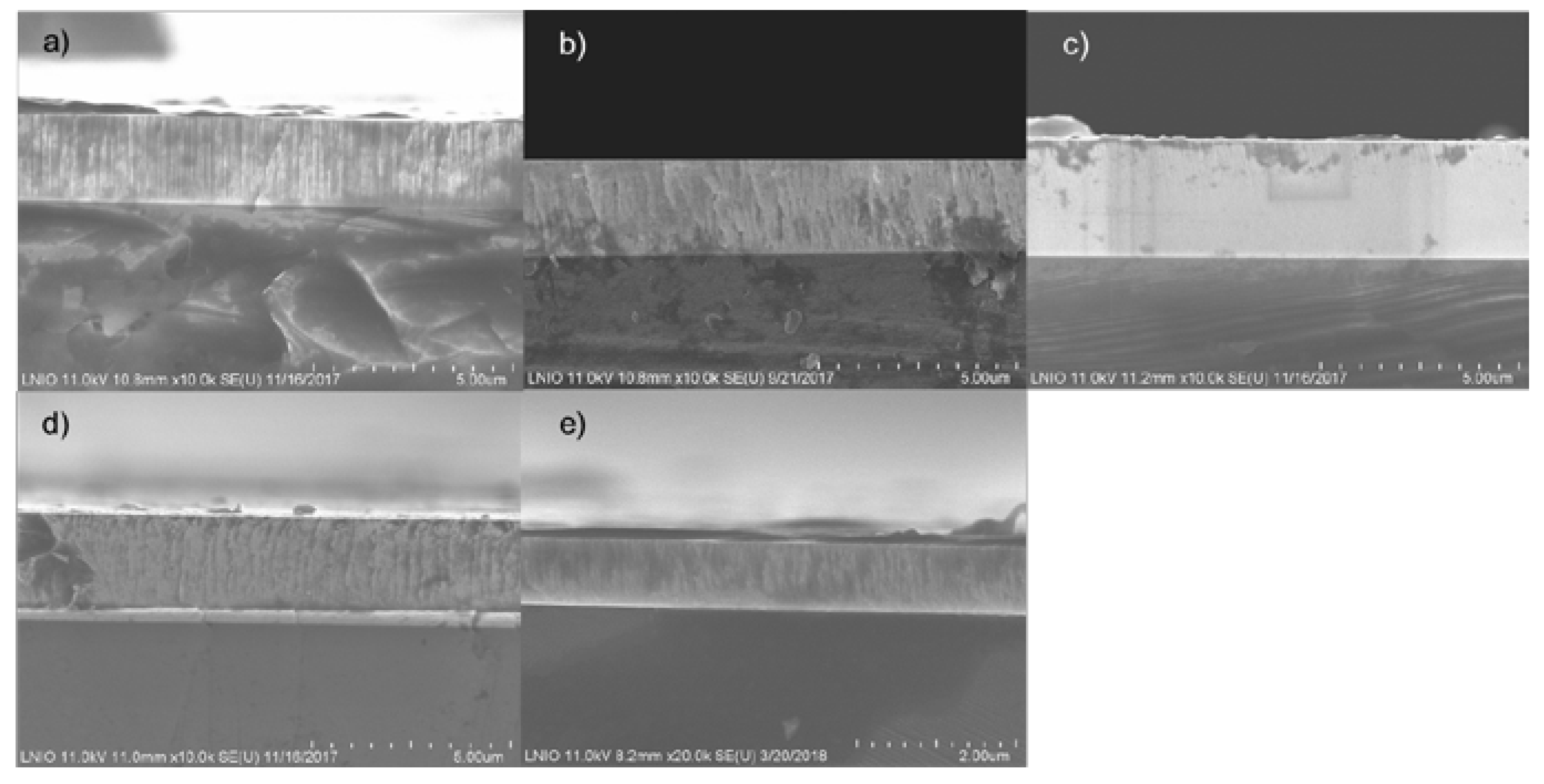
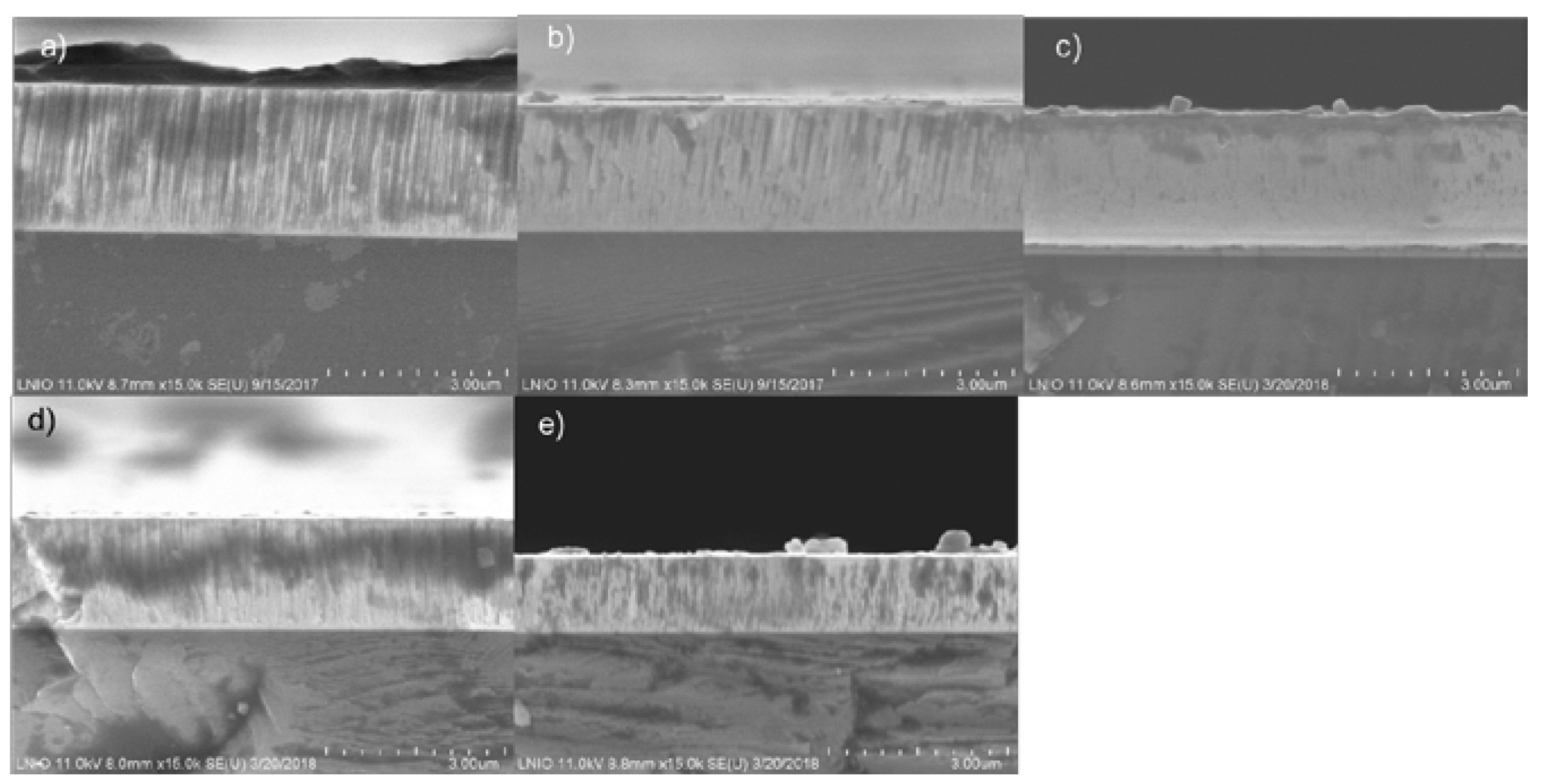
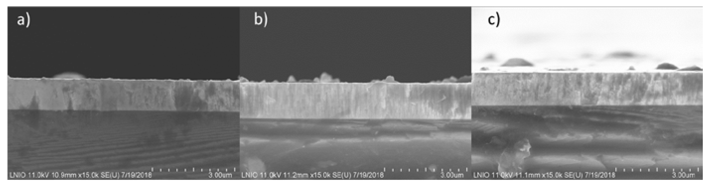
The measured atomic composition of TaCx and HfCx coatings according to the CH4 flow rates are summarized in Table 3. The carbon content increases as the CH4 flow rate increases for both TaCx and HfCx coatings. Nevertheless, the composition of TaCx coatings seems to remain constant from 4 to 6 sccm of CH4 while keeping a stoichiometric compound without forming an over-stoichiometric coating.
The evolution of TaCx and HfCx coatings structure as a function of the CH4 flow rate is shown in Figure 3 and Figure 4, respectively. When pure Ta is sputtered (Figure 3a), a β-Ta tetragonal structure textured {002}, which is not referenced in the pressure-temperature diagram of Ta [30,31], is obtained. The stable phase α-Ta has a body-centered cubic (bcc) structure. The β-Ta metastable structure is commonly obtained in sputtering processes [32,33,34,35,36]. Collin et al. have proposed a theory explaining the precipitation of this phase [36] by thermodynamic calculations. TEM imagery has revealed the presence of an amorphous tantalum phase (a-TaSi) at the substrate/β-Ta interface. Thermodynamic calculations have shown that growth on the amorphous a-TaSi phase of the β-Ta phase is more favorable than that of the α-Ta phase. A growth with planes (002) parallel to the substrate’s surface, characterized by a strong {002} texture in the XRD pattern (Figure 3a), is an expected result because the film grows according to the planes with the lowest surface energy. However, Bernoulli et al. have proposed another hypothesis based on the observed results in the literature [37]. They assume that the chemical composition of the substrate’s surface (the presence of a native oxide, for example) has a strong influence on the Ta germination and growth.
When 1 sccm of CH4 is introduced (Figure 3b), the α-Ta bcc phase with a {110} texture is stabilized. This could be due to the insertion of carbon in the lattice, which creates a local compressive stress, allowing a tetragonal to bcc transition via lattice contraction. Furthermore, the shortest Ta-Ta distance in the β-Ta tetragonal cell is smaller than that of the α-Ta bcc cell (i.e. 0.265 nm against 0.286 nm, respectively) [38]. It should be easier for carbon to be inserted in the bcc structure, and this could be a reason why tetragonal β Ta is transformed into bcc α-Ta. A fcc nanocristalined TaC structure with a {111} texture is obtained for 2 sccm of CH4. The texture is lost when DCH4 increases until 6 sccm. The loss of preferential orientation can be explained by a reduced adatom mobility associated with alower bombardment of the growing film.
The evolution of TaC0.76 microstructure across the film by TEM is shown in Figure 5. The Selected Area Electron Diffraction (SAED) patterns confirm the presence of a TaC fcc crystalline phase. However, both the microstructure and crystalline orientation evolve following the selected zone within the film. Near the substrate/film’s interface (Figure 5a,b), a polycrystalline film growth with equiaxed grain oriented following the <111> direction is observed. When the coating becomes thicker (Figure 5c–f), a columnar microstructure appears. The <111> preferential orientation is also reinforced. This is a common phenomenon of thin film growth [39], and this is consistent with the XRD pattern in Figure 3d. Twin grains can also be observed (Figure 5c).
The evolution of the HfCx coatings structure is similar to that of the TaCx coatings. Nevertheless, the stable hcp α-Hf metallic structure with a {002} texture is first obtained when the Hf target is sputtered in pure argon (Figure 4a). When 1 sccm of CH4 is introduced (Figure 4b), the α-Hf phase remains hcp, but the insertion of carbon leads to the peak shift toward smaller angles because of the lattice’s distortion associated with the carbon atom’s insertion. Figure 6a confirms the coating’s hcp structure. Indeed, the FFT carried out with an HRTEM image, coupled to the theoretical pattern with the [100] zone axis, calculated using jems software (Figure 6b), helps to highlight this structure.
From 2 to 6 sccm of CH4, a NaCl fcc structure of the carbide phase (HfC) is obtained where the {111} texture is also progressively lost. TEM microscopy (Figure 7) also shows an fcc structure. Nevertheless, a halo on the FFT, Figure 7c, reveals the presence of an amorphous phase. This is probably an a-C:H phase commonly encountered in transition metal carbide coatings [26].
Concerning TaxHf1-xCy coatings, Figure 8 shows the microstructure of a coating where 3A and 1A were applied to the Ta and Hf targets, respectively. It reveals a nanostructured coating where the period is 2.2 nm. If the period is predicted with Equation (1), the experimental period is consistent with the calculated period:
= e n n . t
where (nm) is the period, en (nm) is the coating’s thickness, n (rpm) is the rotation speed, and t (min) is the deposition time. The calculated period is about 2 nm in our conditions.
The XRD patterns (Figure 9) show a crystalline monophasic fcc material, which is a result coming from the superlattice TaC/HfC coating. The chemical composition does not influence the coatings’ crystallographic structure.

3.3. Morphology

The evolution of TaCx and HfCx coatings’ morphology is shown in Figure 10 and Figure 11, respectively. They exhibit a very similar evolution when DCH4 increases. Pure metals (Ta and Hf) have a columnar morphology, probably due to the high working pressure (1 Pa), which limits the adatom’s mobility to create a compact morphology. When CH4 is introduced, the morphology loses its columnar character to become glassy. This effect can be observed in Figure 10c and Figure 11c when 2 sccm of CH4 are used. This effect must be related to the size of the grain, which might be very fine. This is consistent with XRD patterns (Figure 3c and Figure 4c) where the peaks are wide, traducing a nanocrystalline structure. The columnar growth is observed when DCH4 continues to increase due to the carbide phase crystallization and the growth of grains.
The evolution of the morphology of TaxHf1-xCy coatings as a function of the applied current target is shown in Figure 12. The obtained morphologies are relatively compact; nevertheless, when 2A is applied on both targets, the appearance of columns can be highlighted.

3.4. Mechanical Properties

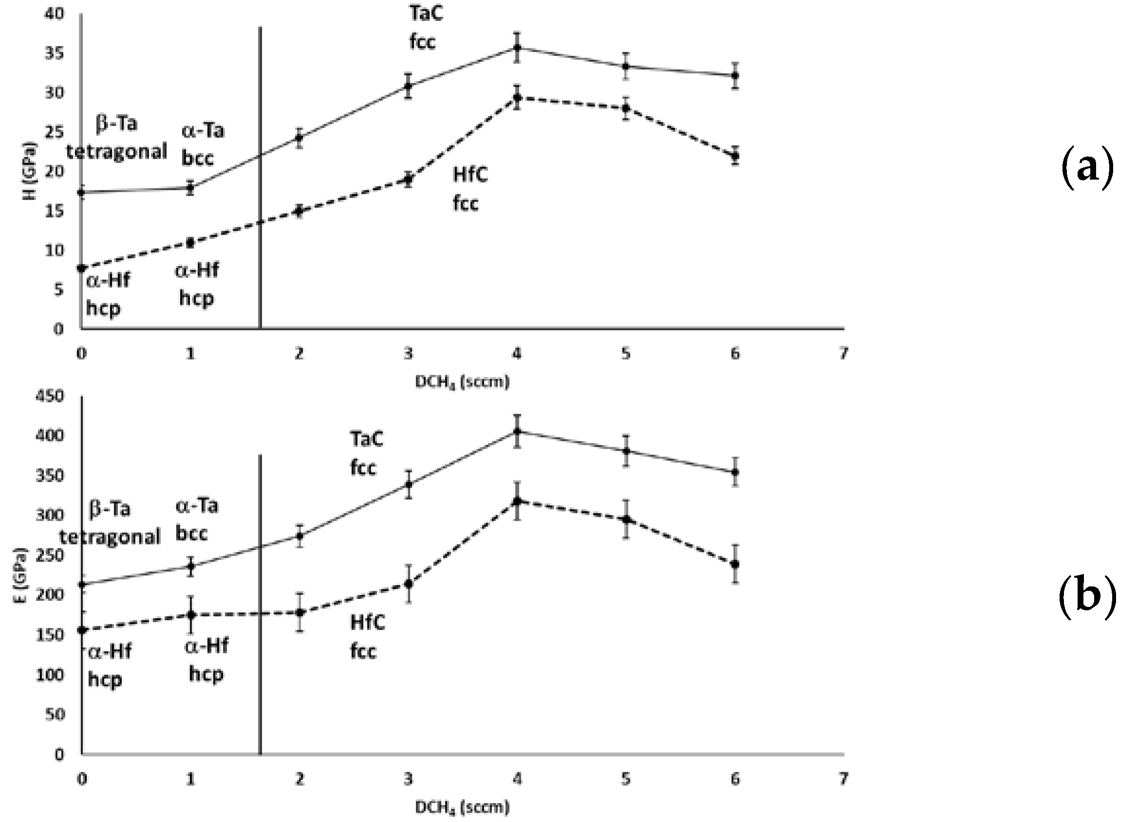
3.4.1. Nanoindentation

The evolution of the coating’s hardness and Young’s modulus is shown in Figure 13.
For both TaCx and HfCx coatings, mechanical properties are enhanced when DCH4 increases from 1 to 4 sccm. This should be due to carbide precipitation (TaC and HfC fcc-structured) with a higher covalent bond degree (between Ta or Hf and C) and to the film’s morphology (corresponding to the observed morphologies in Section 3.4). Nevertheless, when DCH4 = 5 and 6 sccm, both the coating’s hardness and Young’s modulus drop. This is a well known effect due to the presence of a carbon-based amorphous phase (a-C:H) (as can be seen in Figure 7), which is harmful to the hardness and Young’s modulus, as shown in [20]. Moreover, the morphology is open-columnar for the higher CH4 flow rates. Pure Ta and Hf reach a hardness and Young’s modulus of about 17 and 213 GPa for Ta, respectively, and 8 and 156 GPa for Hf, respectively. The hardness and Young’s modulus of TaCx are between 18 and 36 GPa and between 236 and 405 GPa, respectively. The hardness and Young’s modulus of HfCx are between 11 and 29 GPa and between 175 and 318 GPa, respectively. This is consistent with values found in the literature and reported in Table 4.
The measured hardness and Young’s modulus of TaxHf1-xCy coatings are reported in Table 5. The measured values are consistent with other values found in the literature on bulk materials [40,41,42,43]—i.e., 23 GPa for hardness and 240 GPa for Young’s modulus. Nevertheless, the composition does not influence strongly either the hardness or Young’s modulus.

3.4.2. Residual Stresses

Figure 14 shows the evolution of the residual stresses of TaCx (Figure 14a) and HfCx (Figure 14b) coatings according to the CH4 flow rate. The compressive stresses in both coatings rise significantly with the increase in carbon content; i.e., it increases from −350 MPa to −1750 MPa for TaCx and from −200 MPa to −1600 MPa for HfCx. This is linked to the lattice deformation due to the carbon incorporation. This is consistent with Windishmann’s model, based on volumetric distortions caused by the atom’s displacement [44]. Moreover, the coating compaction due to the insertion of carbon (Figure 10b and Figure 11b) participates in this phenomenon. Indeed, the interatomic repulsive forces lead to a compressive macro-state stress in the film [45]. At a high carbon content, the compressive stresses become weaker. This is consistent with the coatings’ columnar morphology (Figure 10e and Figure 11e). According to Hoffman’s model, the interaction of the columns between them generates tensile stresses [46,47]. Hence, the diminution of residual stresses within TaCx and HfCx coatings at high carbon content results from a competition between the tensile and compressive stresses. A similar effect is shown in Figure 15 for TaxHf1-xCy coatings, where the residual stresses are reduced when 2A is applied on both targets, where a columnar morphology is found. The residual stresses of ternary coatings are strongly reduced compared to the binary coatings, due to the rotation of substrates, which limits their bombardment.

4. Conclusions

The properties (structure, morphology, and mechanical properties) of TaxHf1-xCy thin films synthesized by reactive magnetron sputtering (with CH4 as the reactive gas) have been evaluated.
Concerning binary coatings, the deposition rate progressively decreases as the CH4 flow rate increases due to the target’s poisoning. The HfCx or TaCx coating structure can be controlled by tuning the CH4 flow rate. A β-Ta (with a tetragonal structure {002} textured) phase is firstly obtained, and the α-Ta phase (bcc structure) is stabilized when DCH4 = 1 sccm. The TaC phase crystalizes from 2 sccm of CH4 with a {111} texture, which is lost when DCH4 increases until 6 sccm. Concerning the Hf-C system, the α-Hf (the hcp structure with a {002} texture) is primarily sputtered and keeps this structure when 1 sccm of CH4 is used. The HfC phase fcc {111} textured is synthesized at 2 sccm of CH4. The texture is also progressively lost as DCH4 increases. Both Ta and Hf coatings exhibit a compact-columnar morphology. When CH4 is introduced in the gas mixture, the coating’s morphology becomes glassy due to the nano-grain sizes. However, when more reactive gas is used, an open-columnar growth is observed. TEM microscopy has allowed one to highlight the amorphous a-C:H phase when 6 sccm of CH4 is added to the Ar-Hf discharge. The hardness and Young’s modulus of TaCx coatings reach 36 and 405 GPa, respectively. Concerning HfCx coatings, the hardness and Young’s modulus reach 29 and 318 GPa. Nevertheless, the mechanical properties, with a high carbon content, drop. This is assumed to be related to the presence of an amorphous a-C:H phase.
Concerning ternary coatings, nanostructured TaxHf1-xCy coatings were synthesized by co-sputtering in reactive conditions. The period between TaC/HfC nanolayers was measured at 2 nm, while forming an fcc superlattice. The hardness and Young’s modulus are not influenced by the coating’s composition and were found to be 23 and 240 GPa, respectively. The compressive stresses around 10 MPa are relatively weak, due to the rotation of substrates.

Author Contributions

Conceptualization, M.F., A.B. and F.S.; Methodology, M.C., J.G., S.A. and F.S.; Validation, A.B. and F.S.; Formal analysis, A.d.M., H.L., M.C., A.B. and F.S.; Investigation, A.d.M., H.L. and J.G.; Resources, F.S.; Data curation, A.M., H.L. and J.G.; Writing—original draft preparation, A.d.M.; Writing—review and editing, A.B. and F.S.; Supervision, F.S.; Project administration, A.d.M., and F.S.; Funding acquisition, F.S. All authors have read and agreed to the published version of the manuscript.

Acknowledgments

The authors would like to thank GIP 52 for their financial support.

Conflicts of Interest

The authors declare no conflict of interest.

References

  1. Fotovvati, B.; Namdari, N.; Dehghanghadikolaei, A. On Coating Techniques for Surface Protection: A Review. J. Manuf. Mater. Process. 2019, 3, 28. [Google Scholar] [CrossRef] [Green Version]
  2. Aoudia, K.; Lamri, S.; Achache, S.; Retraint, D.; Verdy, C.; Langlade, C.; Azem, S.; Sanchette, F. Structural and Mechanical Properties of Arc-Sprayed Ni–Cr Coating Post-Treated by Surface Mechanical Attrition Treatment (SMAT). Coatings 2018, 8, 424. [Google Scholar] [CrossRef] [Green Version]
  3. Dehghanghadikolaei, A.; Fotovvat, B. Coating Techniques for Functional Enhancement of Metal Implants for Bone Replacement: A Review. Materials 2019, 12, 1795. [Google Scholar] [CrossRef] [Green Version]
  4. Sahith, M.S.; Giridhara, G.; Suresh Kumar, R. Development and analysis of thermal barrier coatings on gas turbine blades–A Review. Mater. Today Proc. 2018, 5, 2746–2751. [Google Scholar] [CrossRef]
  5. Mehboob, G.; Liua, M.; Xu, T.; Hussain, S.; Mehboob, G.; Tahir, A. A review on failure mechanism of thermal barrier coatings and strategies to extend their lifetime. Ceram. Int. in press. [CrossRef]
  6. Alhussein, A.; Achache, S.; Deturche, R.; Sanchette, F.; Pulgarin, C.; Kiwi, J.; Rtimi, S. Beneficial effect of Cu on Ti-Nb-Ta-Zr sputtered uniform/adhesive gum films accelerating bacterial inactivation under indoor visible light. Colloids Surf. B Biointerfaces 2017, 152, 152–158. [Google Scholar] [CrossRef]
  7. Creus, J.; Idrissi, H.; Mazille, H.; Sanchette, F.; Jacquot, P. Corrosion behaviour of AllTi coating elaborated by cathodic arc PVD process onto mild steel substrate. Thin Solid Film. 1999, 346, 150–154. [Google Scholar] [CrossRef]
  8. Creus, J.; Berziou, C.; Cohendoz, S.; Perez, A.; Rebere, C.; Reffass, M.; Touzain, S.; Allely, C.; Gachon, Y.; Heau, C.; et al. Reactivity classification in saline solution of magnetron sputtered or EBPVD pure metallic, nitride and Al-based alloy coatings. Corros. Sci. 2012, 57, 162–173. [Google Scholar] [CrossRef]
  9. Lomello, F.; Sanchette, F.; Schuster, F.; Tabarant, M.; Billard, A. Influence of bias voltage on properties of AlCrN coatings prepared by cathodic arc deposition. Surf. Coat. Technol. 2013, 224, 77–81. [Google Scholar] [CrossRef]
  10. Arab Pour Yazdi, M.; Lomello, F.; Wang, J.; Sanchette, F.; Dong, Z.; White, T.; Wouters, Y.; Schuster, F.; Billard, A. Properties of TiSiN coatings deposited by hybrid HiPIMS and pulsed-DC magnetron co-sputtering. Vacuum 2014, 109, 43–51. [Google Scholar] [CrossRef]
  11. Cotton, J. Ultra-High-Temperature Ceramics. Adv. Mater. Process. 2010, 168, 26–28. [Google Scholar]
  12. Paul, A.; Binner, J.; Vaidhyanathan, B. UHTC Composites for Hypersonic Applications. In Ultra-High Temperature Ceramics; Fahrenholtz, W.G., Wuchina, E.J., Lee, W.E., Zhou, Y., Eds.; John Wiley & Sons, Inc.: Hoboken, NJ, USA, 2014; pp. 144–166. [Google Scholar] [CrossRef] [Green Version]
  13. Qualification of New UHTC Materials for Solar Receiver at High Temperature –PROMES. Available online: https://www.promes.cnrs.fr/index.php?page=qualification-of-new-uhtc-materials-for-solar-receiver-at-high-temperature (accessed on 19 March 2018).
  14. Sani, E.; Mercatelli, L.; Fontani, D.; Sans, J.-L.; Sciti, D. Hafnium and tantalum carbides for high temperature solar receivers. J. Renew. Sustain. Energy 2011, 3, 063107. [Google Scholar] [CrossRef] [Green Version]
  15. Fahrenholtz, W.G.; Wuchina, E.J.; Lee, W.E.; Zhou, Y. (Eds.) Ultra-High Temperature Ceramics: Materials for Extreme Environment Application; John Wiley & Sons, Inc.: Hoboken, NJ, USA, 2014. [Google Scholar] [CrossRef] [Green Version]
  16. Martin, D.S. Advances in Inorganic Chemistry and Radiochemistry; Emeléus, H.J., Sharpe, A.G., Eds.; Elsevier: Amsterdam, The Netherlands, 2002; Volume 4. [Google Scholar] [CrossRef]
  17. Cedillos, O.; Jayaseelan, D.; Lee, B. Fabrication of TaC-HfC Ceramics for Ultra-High Temperature Applications, Ultra-High Temperature Ceramics: Materials for Extreme Environmental Applications II. 2012. Available online: http://dc.engconfintl.org/uhtc/25 (accessed on 2018).
  18. Cedillos-Barraza, O.; Manara, D.; Boboridis, K.; Watkins, T.; Grasso, S.; Jayaseelan, D.D.; Konings, R.J.M.; Reece, M.J.; Lee, W.E. Investigating the highest melting temperature materials: A laser melting study of the TaC-HfC system. Sci. Rep. 2016, 6, 37962. [Google Scholar] [CrossRef] [PubMed] [Green Version]
  19. Lasfargues, H.; Glechner, T.; Koller, C.M.; Paneta, V.; Primetzhofer, D.; Kolozsvári, S.; Holec, D.; Riedl, H.; Mayrhofer, P.H. Non-reactively sputtered ultra-high temperature Hf-C and Ta-C coatings. Surf. Coat. Technol. 2017, 309, 436–444. [Google Scholar] [CrossRef]
  20. Evans, R.D.; Doll, G.L.; Glass, J.T. Mechanical property development in reactively sputtered tantalum carbide/amorphous hydrocarbon thin films. J. Mater. Res. 2006, 21, 1500–1511. [Google Scholar] [CrossRef]
  21. Evans, R.D.; Doll, G.L.; Meng, W.J.; Mei, F.; Glass, J.T. Effects of applied substrate bias during reactive sputter deposition of nanocomposite tantalum carbide/amorphous hydrocarbon thin films. Thin Solid Film. 2007, 515, 5403–5410. [Google Scholar] [CrossRef]
  22. Evans, R.D.; Howe, J.Y.; Bentley, J.; Doll, G.L.; Glass, J.T. Influence of Deposition Parameters on the Composition and Structure of Reactively Sputtered Nanocomposite TaC/a-C:H Thin Films. J. Mater. Res. 2005, 20, 2583–2596. [Google Scholar] [CrossRef]
  23. Vargas, M.; Castillo, H.A.; Restrepo-Parra, E.; De La Cruz, W. Stoichiometry behavior of TaN, TaCN and TaC thin films produced by magnetron sputtering. Appl. Surf. Sci. 2013, 279, 7–12. [Google Scholar] [CrossRef]
  24. Shuo, W.; Kan, Z.; Tao, A.; Chaoquan, H.; Qingnan, M.; Yuanzhi, M.; Mao, W.; Weitao, Z. Structure, mechanical and tribological properties of HfCx films deposited by reactive magnetron sputtering. Appl. Surf. Sci. 2015, 327, 68–76. [Google Scholar] [CrossRef]
  25. Li, G. Microstructure and mechanical properties of hafnium carbide coatings synthesized by reactive magnetron sputtering. J. Coat. Technol. Res. 2010, 7, 403–407. [Google Scholar] [CrossRef]
  26. Jansson, U.; Lewin, E. Sputter deposition of transition-metal carbide films—A critical review from a chemical perspective. Thin Solid Film. 2013, 536, 1–24. [Google Scholar] [CrossRef]
  27. Yate, L.; Coy, L.E.; Aperador, W. Robust tribo-mechanical and hot corrosion resistance of ultra-refractory Ta-Hf-C ternary alloy films. Sci. Rep. 2017, 7, 3080. [Google Scholar] [CrossRef] [PubMed]
  28. Stoney, G.G. The tension of metallic films deposited by electrolysis. Proc. R. Soc. Lond. A 1909, 82, 172–175. [Google Scholar] [CrossRef] [Green Version]
  29. Achache, S.; Lamri, S.; Alhussein, A.; Billard, A.; François, M.; Sanchette, F. Gum Metal thin films obtained by magnetron sputtering of a Ti-Nb-Zr-Ta target. Mater. Sci. Eng. A 2016, 673, 492–502. [Google Scholar] [CrossRef]
  30. Young, D.A. Phase Diagrams of the Elements; University of California Press: Berkeley, CA, USA, 1991. [Google Scholar]
  31. Read, M.H.; Altman, C. A new structure in tantalum thin films. Appl. Phys. Lett. 1965, 7, 51–52. [Google Scholar] [CrossRef]
  32. Baker, P.N. Preparation and properties of tantalum thin films. Thin Solid Film. 1972, 14, 3–25. [Google Scholar] [CrossRef]
  33. Westwood, W.D.; Boynton, R.J.; Wilcox, P.S. The effects of argon pressure on the properties of sputtered tantalum films. Thin Solid Film. 1973, 16, 1–25. [Google Scholar] [CrossRef]
  34. Gerstenberg, D.; Calbick, C.J. Effects of nitrogen, methane, and oxygen on structure and electrical properties of thin tantalum films. J. Appl. Phys. 1964, 35, 402–407. [Google Scholar] [CrossRef]
  35. Kwon, K.-W.; Lee, H.-J.; Sinclair, R. Solid-state amorphization at tetragonal-Ta/Cu interfaces. Appl. Phys. Lett. 1999, 75, 935–937. [Google Scholar] [CrossRef]
  36. Colin, J.J.; Abadias, G.; Michel, A.; Jaouen, C. On the origin of the metastable β-Ta phase stabilization in tantalum sputtered thin films. Acta Mater. 2017, 126, 481–493. [Google Scholar] [CrossRef]
  37. Bernoulli, D.; Müller, U.; Schwarzenberger, M.; Hauert, R.; Spolenak, R. Magnetron sputter deposited tantalum and tantalum nitride thin films: An analysis of phase, hardness and composition. Thin Solid Film. 2013, 548, 157–161. [Google Scholar] [CrossRef]
  38. Jiang, A.; Yohannan, A.; Nnolim, N.O.; Tyson, T.A.; Axe, L.; Lee, S.L.; Cote, P. Investigation of the structure of β-tantalum. Thin Solid Film. 2003, 437, 116–122. [Google Scholar] [CrossRef] [Green Version]
  39. Petrov, I.; Barna, P.B.; Hultman, L.; Greene, J.E. Microstructural evolution during film growth. J. Vac. Sci. Technol. A 2003, 21, S117–S128. [Google Scholar] [CrossRef]
  40. Smith, C.J.; Yu, X.-X.; Guo, Q.; Weinberger, C.R.; Thompson, G.B. Phase, hardness, and deformation slip behavior in mixed HfxTa1-Xc. Acta Mater. 2018, 145, 142–153. [Google Scholar] [CrossRef]
  41. Ghaffari, S.A.; Faghihi-Sani, M.A.; Golestani-Fard, F.; Mandal, H. Spark plasma sintering of TaC–HfC UHTC via disilicides sintering aids. J. Eur. Ceram. Soc. 2013, 33, 1479–1484. [Google Scholar] [CrossRef]
  42. Gaballa, O. Processing development of 4TaC-HfC and related carbides and borides for extreme environments. Grad. Theses Diss. 2012. [Google Scholar] [CrossRef]
  43. Kurbatkina, V.V.; Patsera, E.I.; Levashov, E.A.; Timofeev, A.N. Self-propagating high-temperature synthesis of single-phase binary tantalum-hafnium carbide (Ta,Hf) C and its consolidation by hot pressing and spark plasma sintering. Ceram. Int. 2018, 44, 4320–4329. [Google Scholar] [CrossRef]
  44. Windischmann, H. Intrinsic stress in sputter-deposited thin films. Crit. Rev. Solid State Mater. Sci. 1992, 17, 547–596. [Google Scholar] [CrossRef]
  45. Hoffman, D.W.; Thornton, J.A. The compressive stress transition in Al, V, Zr, Nb and W metal films sputtered at low working pressures. Thin Solid Film. 1977, 45, 387–396. [Google Scholar] [CrossRef]
  46. Barth, M.; Ensinger, W.; Hoffmann, V.; Wolf, G.K. Stress and adhesion of chromium and boron films deposited under ion bombardment. Nucl. Instrum. Methods Phys. Res. Sect. B Beam Interact. Mater. At. 1991, 59, 254–258. [Google Scholar] [CrossRef]
  47. Doljack, F.A.; Hoffman, R.W. The origins of stress in thin nickel films. Thin Solid Film. 1972, 12, 71–74. [Google Scholar] [CrossRef]
Figure 1. Evolution of (a) the I T a 0 I A r 0 ratio and (b) the I H α I A r 0 ratio according to the CH4 flow rate (from 1 to 6 sccm) within Ta-Ar discharges and the evolution of (c) the I H f 0 I A r 0 ratio and (d) the I H α I A r 0 ratio according to the CH4 flow rate (from 1 to 6 sccm) within Hf-Ar discharges. For both Ta-Ar and Hf-Ar discharges, the total pressure and discharge current are kept constant at 1 Pa and 2 A, respectively
Coatings 10 00212 g001
Figure 2. Deposition rate as a function of CH4 flow rate at constant current and pressure (2 A and 1 Pa) for (a) TaCx coatings and (b) HfCx coatings.
Coatings 10 00212 g002
Figure 3. XRD patterns for different flow rates. (a) Pure Ta, (b) 1 sccm of CH4, (c) 2 sccm of CH4, (d) 3 sccm of CH4, (e) 4 sccm of CH4, (f) 5 sccm of CH4, and (g) 6 sccm of CH4.
Coatings 10 00212 g003
Figure 4. XRD patterns for different flow rates. (a) Pure Hf, (b) 1 sccm of CH4, (c) 2 sccm of CH4, (d) 3 sccm of CH4, (e) 4 sccm of CH4, (f) 5 sccm of CH4, and (g) 6 sccm of CH4.
Coatings 10 00212 g004
Figure 5. TEM cross section images of TaC0.76 coating. (a) The substrate-film interface, (b) the corresponding SAED, (c) at the middle of the film, (d) the corresponding SAED, (e) at the top of the film, and (f) the corresponding SAED.
Coatings 10 00212 g005
Figure 6. (a) HRTEM image of an HfC0.20 coating. (b) Simulated indexed electron diffraction pattern with a [100] zone axis.
Coatings 10 00212 g006
Figure 7. (a) TEM image of HfC0.95 coating. (b) The corresponding SAED. (c) The HRTEM image of the HfC0.95 coating.
Coatings 10 00212 g007
Figure 8. (a) STEM image of a TaxHf1-xCy coating with 3A and 1A applied on Ta and Hf targets; (b) the measured period.
Coatings 10 00212 g008
Figure 9. XRD patterns of TaxHf1-xCy coatings. (a) 1A on Ta and 3A on Hf, (b) 2A on Ta and 2A on Hf, and (c) 3A on Ta and 1A on Hf.
Coatings 10 00212 g009
Figure 10. Evolution of TaCx coatings morphology. (a) Pure Ta, (b) TaC0.35 with 1 sccm of CH4, (c) TaC0.66 with 2 sccm of CH4, (d) TaC0.76 with 3 sccm of CH4, and (e) TaC1.00 with 6 sccm of CH4.
Coatings 10 00212 g010
Figure 11. Evolution of HfCx coatings morphology. (a) Pure Hf, (b) HfC0.20 with 1 sccm of CH4, (c) HfC0.34 with 2 sccm of CH4, (d) HfC0.60 with 3 sccm of CH4, and (e) HfC0.95 with 6 sccm of CH4.
Coatings 10 00212 g011
Figure 12. Evolution of TaxHf1-xCy coatings morphology. (a) 3A on Ta and 1A on Hf, (b) 2A on Ta and 2A on Hf, and (c) 1A on Ta and 3A on Hf.
Coatings 10 00212 g012
Figure 13. Evolution of (a) hardness and (b) Young’s modulus of TaCx (full lines) and HfCx coatings (dotted lines) according to the CH4 flow rate. The corresponding coating’s structures are reported on the figure. Beyond the horizontal line, the coating’s structure remains fcc.
Coatings 10 00212 g013
Figure 14. Residual stress evolution of (a) TaCx and (b) HfCx coatings as a function of CH4 flow rate. The corresponding coating’s structure is shown in the figure. Beyond the horizontal line, the coating’s structure remains fcc.
Coatings 10 00212 g014
Figure 15. Residual stresses of TaxHf1-xCy coatings as a function of Hf target’s discharge current.
Coatings 10 00212 g015
Table 1. Deposition conditions of Ta, TaCx, Hf, and HfCx.
Deposited MaterialDCH4 (sccm)DAr (sccm) D C H 4 D C H 4 + D A r ( % ) Discharge Current (A)Total Pressure (Pa)
Ta030021
TaCx1–6303.2–16.721
Hf030021
HfCx1–6303.2–16.721
Table 2. Deposition conditions of TaxHf1-xCy coatings.
Ta TargetHf Target
Discharge current (A)1–31–3
Frequency (kHz)5050
Target–substrate distance (cm)1313
Pressure (Pa)11
DCH4 (sccm)88
DAr (sccm)3030
Table 3. Chemical composition of TaCx and HfCx coatings measured by XPS.
CH4 Flow Rate (sccm) T a 4 f ( T a 4 f + C 1 s ) ( atom % ) TaCx Coatings Formula H f 4 f ( H f 4 f + C 1 s ) ( atom % ) HfCx Coatings Formula
117.6TaC0.3510.1HfC0.20
232.9TaC0.6616.8HfC0.34
337.9TaC0.7630.2HfC0.60
451.7TaC1.0340.5HfC0.81
551.8TaC1.0445.1HfC0.90
650.0TaC1.0047.4HfC0.95
Table 4. Reported mechanical properties of TaCx and HfCx coatings included in this work.
AuthorsRef.Deposited
Material
Elaboration
Method
Hardness (GPa)Young’s Modulus (GPa)
D. Bernoulli et al.[38]TaDC magnetron sputtering14not measured
Lasfargues et al.[19]TaCxUnbalanced magnetron sputtering system40400–500
HfCx34–36400–500
Evans et al.[20]TaCxReactive unbalanced magnetron sputtering9–20109–220
Shuo et al.[24]HfCxDC reactive magnetron sputtering10–34not measured
TaReactive pulsed DC magnetron sputtering17213
This work TaCx18–36236–405
Hf8156
HfCx11–29175–318
Table 5. Hardness and Young’s modulus of TaxHf1-xCy coatings.
Coatings3 A on Ta
1 A on Hf
2 A on Ta
2 A on Hf
1 A on Ta
3 A on Hf
DCH4 (sccm)888
H (GPa)22.623.822.8
E (GPa)235249238

