Article

Study on Microstructure and Tribological Performance of Diamond/Cu Composite Coating via Supersonic Laser Deposition

1
Institute of Laser Advanced Manufacturing, Zhejiang University of Technology, Hangzhou 310023, China
2
Collaborative Innovation Center of High-end Laser Manufacturing Equipment, Hangzhou 310023, China
*
Author to whom correspondence should be addressed.
Coatings 2020, 10(3), 276; https://doi.org/10.3390/coatings10030276
Submission received: 15 February 2020 / Revised: 7 March 2020 / Accepted: 8 March 2020 / Published: 17 March 2020

Abstract

:
The supersonic laser deposition (SLD) of diamond/Cu composite powder is studied over a range of laser power. The deposition efficiency, coating microstructure, cohesive/adhesive bonding, phase composition, micro-hardness, and tribological property of the diamond/Cu composite coating are investigated. The results indicate that, as laser power is increased, deposition efficiency initially increases and then declines. The diamond particles distribute uniformly in the composite coating. Due to the increase of velocity ratio and total energy by laser irradiation, the cohesive/adhesive bonding of the composite coating is improved. The composite coating can preserve the phase composition of the origin powders due to the relatively low heat input during the SLD process. Slight oxidation of the Cu powder can be detected in the coatings prepared with high laser power, which has adverse effects on material deposition. The SLD-diamond/Cu composite coating has superior wear-resistance because of low friction coefficient, high micro-hardness, and uniformly distributed diamond particles.

1. Introduction

Owing to extremely high hardness, diamonds are often used as reinforcement particulates in ceramic-metal composite coatings to enhance the surface properties of cutting tools for manufacturing processes [1,2]. It has exceptional characteristics such as superior wear-resistance, excellent thermal conductivity, chemical inertness and low friction coefficient, in addition to extremely high hardness [3,4]. Currently, the common methods to fabricate diamond particulate-reinforced composite coatings include thermal spray [5,6,7] and laser cladding [8,9]. These technologies mostly involve high working temperatures to totally or substantially melt the binder phase in the composite coatings and the surface of underneath substrate. Although melting of deposition materials and substrates is beneficial for interfacial metallurgical bonding, it, however, greatly increases the risk of oxidation, metal phase transition, diamond graphitization, and excessive thermal residual stress, thereby potentially deteriorating the performances of the coatings [10].
Recently, cold spray (CS) has attracted considerable attention to prepare diamond composite coatings owing to its low process temperature and limited thermal effect on both spray materials and substrates [11,12,13,14]. In the CS process, micro-sized powder particles are accelerated to exceed critical deposition velocity in a converging-diverging Laval nozzle by a supersonic inert gas stream and then impact on a substrate or a previously deposited coating at a temperature well below the melting point of the sprayed powder [15]. The effective bonding of powder particles with substrate is achieved as a result of high-velocity impinging and the associated severe plastic deformation. The solid state deposition characteristics of CS enable a viable method to produce temperature/oxidation-sensitive coatings on different substrates without the necessity of special protection conditions. In regard to CS diamond composite coatings, a large volume fraction of soft metal binder is usually required because CS cannot process hard or ceramic materials. Typically, the feedstock materials are either ball-milled or pre-mixed. However, the ball-milling procedure would lead to a serious fracture of the diamond phase, while the employment of pre-mixed powders often results in a decrease of the diamond phase content in the coating compared to the original feedstock due to its low deposition efficiency [16,17]. In order to obtain high diamond content in the composite coating, Lupoi et al. used a novel Cu-coated diamond powder instead of Cu and diamond powder mixture as the feedstock to fabricate composite coatings via CS [18,19]. The results suggested that the original diamond phase was almost completely retained in the coatings, and diamond graphitization was also prevented. However, frequent cracking of the diamond phase was still observed because the Cu coating was too thin to act as a buffer, which therefore led to the direct impacting of diamond particles with each other. In addition, since the formation of CS coating relying on plastic deformation of both particles and substrates, it often suffers from weak bonding strength and low coating density, which causes the reinforcement particles to easily peel off from the coatings [20]. It is common to replace N2 gas with expensive helium to increase particle impact velocity so as to increase effective deposition, and thereby achieve strong bonding strength and high coating density, but this could inevitably elevate the operating costs. Therefore, it is of both scientific and practical significance to develop a novel fabrication method for diamond composite coatings that would enhance the bonding strength and coating density while simultaneously avoiding the graphitization and fracture of diamond particles.
Supersonic laser deposition (SLD), as an emerging material deposition technique which combines the benefits of both laser and CS, is a relatively new method in coating fabrication [21,22,23,24]. It employs heat from a laser beam to soften both spraying particles and substrates during the CS process, which allows the formation of coating at a much reduced impact velocity of particles using cheap N2 as carrier gas. SLD has been employed to deposit a wide range of materials including pure metals, high strength alloys, metal-ceramic composites, etc. [25,26,27,28,29,30,31,32,33,34,35]. Bray et al. used SLD to fabricate Ti coating with low porosity of only 0.5% [21]; Li et al. demonstrated that laser irradiation significantly improved the coating/substrate bonding strength of SLD-Cu coating [25]; Yang et al. successfully obtained diamond/Ni60 composite coating by SLD without diamond graphitization [33]; Li et al. prepared WC/Stellite-6 composite coating by SLD with high WC content [35]. Based on these results, it can be concluded that SLD has the potential to fulfill the above-mentioned requirements of a novel fabrication method for diamond-reinforced composite coatings.
In this study, diamond/Cu composite coatings were prepared by SLD under different laser powers. The influence of laser irradiation on deposition efficiency, coating microstructure, cohesive/adhesive bonding, and phase composition is systematically investigated. The micro-hardness and tribological property of the SLD diamond/Cu coatings were also studied to elucidate the effect of diamond particulate introduction on the properties of the SLD coating. The results of this study will provide guidance in employing SLD to fabricate diamond particulate-reinforced composite coatings, especially those with oxidation/heat-sensitive metals as binder phase.

2. Materials and Methods

2.1. Feedstock Materials

Commercially available pure Cu powder and artificial diamond particles were used as the feedstock materials. Figure 1 shows the morphology and size distribution of the feedstock materials which were obtained respectively with scanning electron microscope (Carl Zeiss ULTRA, Oberkochen, Germany) and laser diffraction particle size analyzer (Horiba LA-950, Kyoto, Japan). As shown in Figure 1, the particle shape of the Cu powder and the diamond particles is spherical and irregular, respectively. The average size of the Cu powder and the diamond particles are 11.36 and 17.76 μm, respectively, which lie in the range of particle size commonly used in CS. For smaller diamond particles such as nano-particles, because of their light weight and thus small momentum, it is difficult for them to overcome the de-acceleration effect by shock wave on the surface of substrate and reach the substrate to achieve effective deposition. Therefore, the micro-sized diamond particles with irregular shape were used in this study. The composite powder consisting of 20 wt.% diamond and 80 wt.% Cu was mechanically ball-milled in a cylinder rotating at a speed of 200 rpm for 1 hr. The morphology and size distribution of the post-milled composite powder are shown in Figure 2. No fracture of the starting materials is found, which is attributed to the relatively low rotating speed during the ball milling process. The average size of the ball-milled powders was measured to be 17.63 μm. The substrate material is pure Cu with a purity of 99.9%. The substrate specimen has a dimension of 100 × 50 × 5 mm3. In order to enhance interfacial bonding between coating and substrate, the substrate surface was grit-blasted using 24 mesh alumina before deposition so as to increase the surface roughness, and then the grit-blasted substrate was ultrasonic cleaned in alcohol.

2.2. Coating Fabrication

The schematic diagram of the SLD system used in this study is shown in Figure 3, which consists of laser unit, CS unit, high pressure gas supply unit and temperature/power monitoring, and controlling unit. High pressure N2 gas or compressed air was divided into two parts: one passed through the heater, and the other was via a powder feeder where feedstock powders were held. The feedstock stream and high-pressure carrier gas mixed and passed through the Laval nozzle where they were accelerated to supersonic speeds. The high-velocity flying particles impacted a small area of the substrate that was synchronously irradiated by a continuous wave diode laser (LDF-4.000, Laserline, Koblenz, Germany) with a maximum power of 4 kW. The laser spot was 5 mm in diameter with a near top hat intensity distribution. A high-speed infra pyrometer was coupled with laser head to monitor and control the temperature, and thus real-time altered the laser output power. The CS nozzle, laser head, and pyrometer were assembled on a robot (STAÜBLI TX 90, Pfaeffikon, Switzerland). During the SLD process, the substrate kept stationary and the nozzle, laser head, and pyrometer were movable. The spraying nozzle was perpendicular to the substrate surface, and the laser beam was at an angle of 30° to the surface normal. The deposition zone and laser spot matched well with each other. Because of the softened substrate and powder particles by means of laser heating, the diamond/Cu composite coating could be formed at a relatively low impacting velocity. Therefore, N2 gas was used in this study to replace helium as working gas to accelerate the composite powder. The CS parameters including working gas type, gas temperature, spraying distance, powder feeding rate, and scanning speed were kept constant on the basis of a series of process optimization experiments with only laser power varied. All SLD diamond/Cu composite coatings were deposited using a spray distance of 30 mm, scan velocity of 10 mm/s, powder feed rate of 40 g/min, and N2 gas pressure, and temperature of 3 MPa and 500 °C, respectively. The coatings a, b, c, d, e, and f were deposited using laser power of 0, 0.5, 1.0, 1.5, 2.0, and 2.5 kW, respectively.

2.3. Coating Characterization

The coating specimens were cross-sectioned perpendicular to the coating surface with electrical discharge wire cutting, followed by conventional metallography preparation procedures. The specimens were ground with SiC papers and polished with colloidal alumina suspension and were then etched by corrosive solution consisting of 1 mL FeCl3, 4 mL HNO3, and 12 mL HCl. The cross-sectional microstructures of coating were examined with optical microscopy (OM, Axio Scope. A1, Zeiss) and scanning electron microscope (SEM, EVO 18, Carl Zeiss). The energy dispersive spectrometer (EDS, Nano Xflash Detector 5010, Bruker, Billerica, MA, USA) was used to analyze element distribution of the coatings. The phase structure of the diamond/Cu composite feedstock powder and the composite coatings were analyzed with X-ray diffraction (XRD, D8 Advance, Brucker) using Cu-Kα radiation, 45 kV, 40 mA, and a scan rate of 0.02°/s. The micro-hardness of the coatings was measured on micro level from the coating surface to the substrate at a constant interval of 0.1 mm using a Vickers Indenter (HMV-G-FA, SHIMADZ, Kyoto, Japan). The weight and duration used for each hardness measurement were 1.96 N and 10 s. Pin-on-disc wear test was conducted on the coatings at room temperature under dry sliding conditions. The pin was a Si3N4 ceramic ball. The disk was the coating specimen which was polished, cleaned in an ultrasonic bath, and finally dried. The test was conducted under three loads of 6, 9, and 12 N at a rotational speed of 500 rpm. The diameter of wear ball is 5 mm. The evolutions of friction coefficient of the test specimens were recorded during the wear processes.

3. Results and Discussion

3.1. Deposition Efficiency

The typical cross-sectional microstructures of the diamond/Cu composite coatings prepared under various laser powers from 0 to 2.5 kW are shown in Figure 4. The interfaces between coatings and substrates are highlighted by a dotted line so as to clearly distinguish the coatings from substrates in the cross section. The variation in the coating with laser power is observed. It can be found that all coatings are macroscopically continuous and dense without cracks and pores. Further observation from SEM images with high magnifications (Figure 5) indicates that the CS coating has cracks and pores while SLD coating does not, which is due to the change of material’s plastic deformation ability by laser irradiation. In the coating process, coating thickness is usually taken as an index to qualitatively evaluate the deposition efficiency of feedstock powder. Because the SLD coatings show pyramidal morphologies, the peak coating thickness as indicated in Figure 4 was thus obtained by image analysis software to characterize deposition efficiency. As can be seen from Figure 4a, the peak coating thickness of the diamond/Cu composite coating deposited under 0 kW (CS coating) is about 1393.01 μm. With the assistance of 0.5 kW laser irradiation (SLD-0.5 kW coating), the peak coating thickness is slightly increased to 1459.28 μm (Figure 4b). Further increasing the laser power to 1.0 kW, the peak coating thickness shows a substantial increase to 2238.52 μm as seen in Figure 4c. However, as the laser power was further increased, the peak coating thickness is 2105.22, 2028.24, and 1969.82 μm corresponding to the laser power of 1.5, 2.0, and 2.5 kW, respectively, as indicated in Figure 4d to Figure 4f. In other words, the peak coating thickness exhibits a decrease trend as the laser power exceeds 1.0 kW. However, it should be stressed that all the SLD coatings have higher peak coating thickness than the CS coating in this study, which implies that introduction of laser irradiation into the CS process did enhance the deposition efficiency of the composite powder.
In order to determine quantitatively the variation of deposition efficiency with laser power, the weight change (∆m in g) of the substrate was measured after a deposition time (t in min), and then deposition rate (Rd in g/min) was calculated by the definitional equation as follows:
R d = Δ m t
The powder feeding rate (Rf in g/min) was 40 g/min in this study, which remained constant for all the coatings during the deposition process. Therefore, the deposition efficiency (DE) can be obtained via dividing the deposition rate (Rd) by the powder feeding rate (Rf) as described below:
D E = R d R f × 100 %
Table 1 summarizes the weight changes, deposition time, and powder feeding rate along with the calculated deposition rates and deposition efficiencies for all the coatings. The results are obtained by calculating the average value of three time tests for each sample, and thus the standard deviations are also provided in Table 1. It can be seen apparently from Table 1 that the deposition efficiency of the coatings increases firstly and then decreases with increasing laser power, which is in good agreement with the results of peak coating thickness demonstrated in Figure 4. The deposition efficiency reaches its maximum value of 53.8% when 1.0 kW laser power was employed. Although the deposition efficiencies of the coatings gradually decrease as the laser power increases from 1.0 kW to 2.5 kW, all the SLD coatings (especially those produced with laser power ≥1.0 kW) have higher deposition efficiencies than the counterpart produced by CS.
In the CS process, the effective deposition of feedstock powder is to be facilitated only if the particles impinge onto the substrate at or beyond a material-dependent critical velocity. The following formula has been used to theoretically predict the critical velocity (vcr in m/s) for given coating/substrate combination [36]:
v c r = 667 14 ρ + 0.08 T m + 0.1 σ u 0.4 T i
where   ρ   is the material density in g/cm3, Tm is the melting temperature in °C, σu is the material strength in MPa, and Ti is the initial particle temperature in °C. Based on Formula (2), it is straightforward that particle preheating (elevating Ti) would lead to reduction of critical velocity. The main characteristic of CS feedstock powders is that they usually comprise a mixture of particles with various particle sizes as shown in Figure 2. The particle size has opposing effects on the particle impact velocity and the critical velocity. The critical velocity generally decreases with increasing particle size while larger particles are more difficult to accelerate and thus have lower impact velocities. Therefore, only those particles meeting the following condition can successfully bond to the substrate:
η = v p v c r 1
The particle impact velocity (vp) is influenced by various factors including spraying conditions, nozzle specification, and feedstock characteristics. In this study, the CS parameters along with the used spraying nozzle and feedstock materials were kept unchanged for all the coatings, which indicate that all the coatings have identical particle impact velocities. However, the introduction of synchronous laser irradiation into CS can effectively increase the particle temperature and thus lead to thermal softening of the spraying particles. As a consequence, the critical velocity would be decreased to different extents depending on the used laser power and then the proportion of particles meeting the condition (4) would increase. This would result in more particles effectively deposited, thus raising deposition efficiency. In our previous studies, the beneficial effects of laser heating on deposition efficiency have been confirmed for some alloy powders and composite powders such as Stellite 6, WC/SS316L, WC/Stellite 6, diamond/Ni60 [20,28,33,35], in which the deposition efficiencies were monotonously increased with elevating laser inputting energy. However, in the present study, the deposition efficiency of diamond/Cu composite powder increased when laser power was low, but it decreased with further increasing laser power to a high level as demonstrated in Table 1. This phenomenon should be ascribed to the oxidation-sensitivity of micro-sized Cu particles which has been observed in our previous work concerning the deposition of Cu coating by SLD [25]. The formation of ceramic oxide phase on the particle surface will weaken the plastic deformation ability of the deposition particles and thereby increase the critical deposition velocity, which has adverse effects on the deposition efficiency.

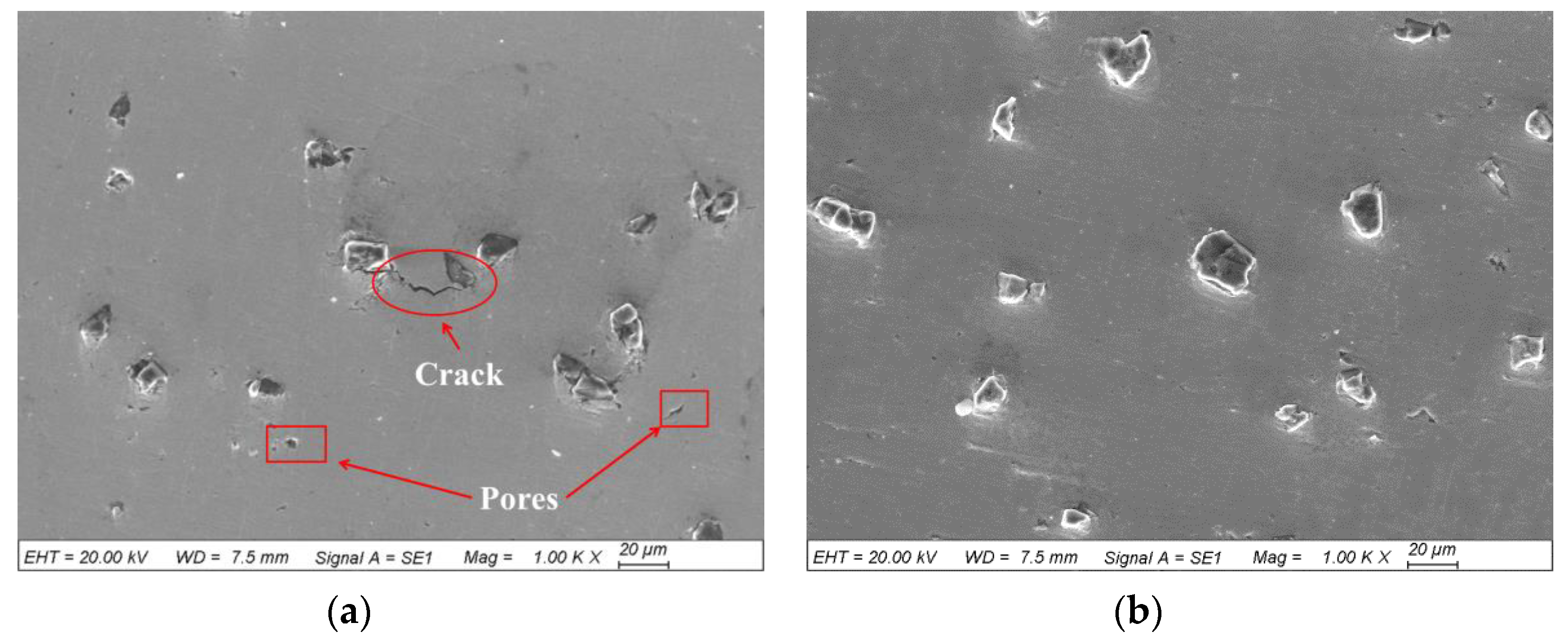
3.2. Coating Microstructure

Figure 6 shows the distribution and retention of diamond particles in the composite coatings produced under different laser powers. It can be found that diamond particles are uniformly distributed in all the coatings. Moreover, one can see that there is no agglomeration of diamond particles in the coatings. It is a common notion that uniform dispersion of the reinforcing particles in a metal matrix composite coating is of great importance for the final properties such as wear/corrosion/oxidation-resistance of the coating. The retention of diamond particles in the coatings is almost the same level for all the coating specimens as indicated in Figure 6. This implies that laser irradiation did not benefit the diamond retention in the composite coatings, which is different from the results reported previously for SLD diamond/Ni60 composite coatings [33]. In that study, the diamond contents in the composite coatings increased with increasing laser irradiation temperature. This discrepancy is due to different metal binder phases selected. The Ni60 alloy is a self-fluxing Ni-based alloy, which has an excellent ability to hold the embedded diamond particles when it is heated; the Cu matrix, however, has poor interfacial wettability with diamond particles, which would result in the rebound effect of incident diamond particles and thus low diamond retention. Recently, Aldwell et al. [18] used Cu/Ni-coated diamond particles as feedstock materials to prepare metal-diamond composite coatings with CS. The thin soft Cu/Ni layer experiencing high plastic deformation acted as the binder phase while the incident diamond particles suffered from extremely high impact stress, thus shattering into many small pieces that penetrated into the soft Cu/Ni metal matrix, forming the composite coating. Although this method can significantly improve the weight fraction of diamond in the coating, the diamond fracture cannot be avoided. The pre-coated diamond particles mixed with Cu powder are to be used as feedstock materials in our ongoing SLD experimental to further optimize the diamond content in the as-prepared composite coatings.
The SEM images of the CS and SLD coatings with high magnification are given in Figure 7, which show the bonding characteristics between Cu matrix and diamond reinforcing particles. Based on the above analysis, the SLD coating prepared with 1.0 kW laser power is the best. Therefore, the following comparisons were conducted between the CS and SLD coating prepared with this power to elucidate the effects of laser irradiation on the coating formation. It can be found from Figure 7 that the diamond particles remained complete (not fractured) for both CS and SLD coatings. This is due to full dissipation of kinetic energy into the plastic deformed Cu particles. However, for the CS coating, there are obvious gaps between Cu matrix and diamond particles, as seen in Figure 7a. On the contrary, diamond particles are tightly enclosed with Cu matrix in the SLD coating, as shown in Figure 7b. Moreover, the Cu matrix surrounding diamond particles underwent severe plastic deformation, causing material extrusion characteristics, as indicated by arrows in Figure 7b. For CS composite powders, there is usually a soft metal phase acting as a matrix to allow hard reinforcement particulates to embed into them to form composite coatings. The plastic deformation ability of the metal matrix therefore plays a vital role in the CS process. Due to the softening effect by laser irradiation in the SLD process, the Cu powder particles became easier to deform, which favored lodging incident diamond particles to form intimate bonding, thus improving matrix/reinforcement interfacial bonding, compared with a CS counterpart. This suggestion has been confirmed for the SLD WC/SS316L composite coating in our previous work [20], in which the interfacial bonding between WC particulates and SS316L matrix was gradually improved with increasing the laser heating temperature.

3.3. Cohesive/Adhesive Bonding

In the CS deposition process, there are two types of bonding that should be given attention. One is particle-to-substrate bonding, which is essential to the formation of the first layer of particles; hence, the key for the adhesive strength of the coating to the substrate, and the other is particle-to-particle bonding, which concerns the build-up of the CS coating, thereby accounting for the cohesive strength and relating to physical properties of the deposited material [11]. Figure 8 displays the comparison of coating density between the CS and SLD coatings. The CS coating contains many gaps and pores, as seen in Figure 7a, while the SLD coating has a much denser microstructure, with minimum gaps and pores, as shown in Figure 7b. Porosity measurements using the image analysis software revealed that the porosity of the CS coating was about 3.9% in area, while it was only 0.63% for the SLD specimen. This confirms the beneficial effect of laser irradiation on the cohesive bonding (coating density) of the CS coating. It was reported by Assadi et al. [37] that there was a unique correlation between the cohesive strength and the velocity ratio, viz., the cohesive strength increased with increasing the velocity ratio. As mentioned above, the particle impact velocities (vp) are the same for the CS and SLD coating because of the same CS parameters. However, introduction of laser irradiation to pre-heat spraying particles in the SLD process can reduce the critical velocity (vcr) according to Formula (3). As a result, the SLD coating has higher velocity ratio than the CS one, which in turn results in better cohesive bonding. Furthermore, the critical condition for bonding can be formulated in terms of the total energy (E) of the particle upon impact, which is the sum of kinetic energy (Ek) and thermal energy (Eth)as described below [11]:
E = E k + E t h
E k = 1 2 v p 2
E t h = c p ( T p T r e f )
where cp is the heat capacity, Tp is the initial temperature of particle upon impact, and Tref is a reference temperature (normally taken as room temperature). The larger the total energy, the better the interfacial bonding is. Since the CS parameters were kept constant for all the coatings in this study, the particle impact velocity of SLD was therefore the same as that in the CS, which means that the same kinetic energy (Ek) can be obtained under using CS and SLD methods according to Formula (6). However, in the SLD process, since introducing a laser to pre-heat the deposited particles, the initial temperature (Tp) of the particles was elevated, which led to the increase of the particle thermal energy (Eth) according to Formula (7). Therefore, it can be concluded that the total energy (E) of the SLD coating is greater than that of the CS, thus achieving better interfacial bonding.
As shown in Figure 9 for the coating/substrate interfacial bonding (adhesive bonding) of the CS and SLD coating, there are gaps between the coating and substrate in the CS coating, while it is hard to distinguish the interface between the coating and substrate in the SLD coating. The result suggests that laser irradiation also plays an important role in adhesive bonding in addition to cohesive bonding of SLD coatings. In the CS process, the hardness of substrate is an important factor that influences the adhesion strength. A hard substrate constrains the deformation of the first layer of deposited particles, thus resulting in relatively poor adhesive bonding strength. A soft substrate allows the impacting particles to penetrate deeper into it, facilitating adiabatic shear instability (ASI) on both particle and substrate sides to form strong adhesion bonding. In the SLD process, the applied laser not only pre-heats the spraying particles, but also softens the substrate. The softened substrate would benefit adhesive bonding in the SLD coating, which was also demonstrated from numerical study by other researchers [38,39,40,41].

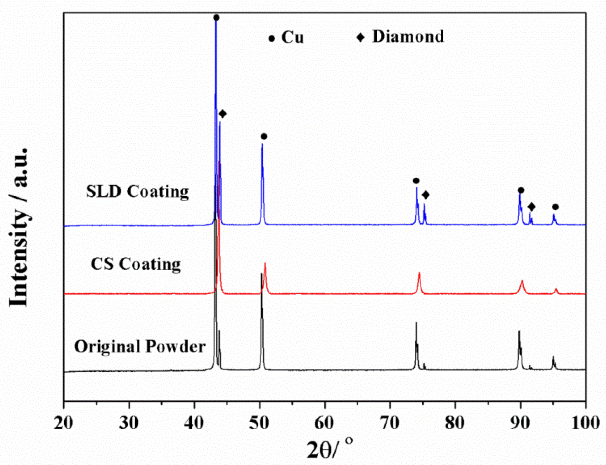
3.4. Phase Composition

In the SLD process, an additional heat source of laser irradiation is introduced. It is therefore necessary to examine the effect of laser introduction on the phase composition of the composite coatings. The XRD patterns of the feedstock powder, CS coating, and SLD coating are given in Figure 10. It can be found that both the CS and SLD coating have almost the same phases as the feedstock powder, confirming that the phase composition of the feedstock powder can be preserved from the SLD process as it retains the solid-state deposition characteristics of CS. Due to the lattice distortion caused by severe plastic deformation of Cu powder, the XRD diffraction peaks of Cu become wider in CS coating, which may cover and thus lead to the disappearance of the weaker diffraction peaks of diamonds. For SLD coating, because the laser is reported to have an annealing effect on the deposited coating [25], diffraction peak broadening of Cu powder will be partly eliminated and then the diffraction peak of diamond can be observed in this coating. For metal deposition methods based on laser melting, high laser power and low scanning velocity are usually used to obtain high heat input, which is required to melt the deposited powder and the substrate. This process has a detrimental effect of phase change, especially for heat-sensitivity materials such as diamond particles. In the SLD process, however, the laser is only to pre-heat the deposited particles and soften the substrate, not to melt them. In this case, low laser power is combined with high scanning velocity. Relatively low heat input would ensure the retaining of original microstructure/phase composition of the feedstock materials, preventing diamond graphitization.
Further EDS analysis was conducted on the CS and SLD coatings, and the results are presented in Figure 11. An oxygen element was detected in all the coatings, but its content increases from 1.02 at.% in the CS coating with laser power in the SLD coating. The O element in the CS coating may be from the feedstock material. The increase of O element in the SLD coatings should be attributed to the reaction of Cu particles with surrounding air when laser irradiation was introduced. The introduction of a laser, on one hand, can effectively soften the deposited particles to improve their ability of plastic deformation, which facilitates material deposition. On the other hand, increasing laser power would elevate the risk of Cu oxidation, which has been reported by other researchers [42,43]. Therefore, in the SLD process, the softening effect and the oxidation reaction induced by laser irradiation compete with each other. When the soften effect overwhelms the oxidation reaction, the deposition efficiency would be improved with increasing laser power, but, when the laser power exceeds a critical value, oxidation reaction would prevail and then the deposition efficiency would decrease with increasing laser power. This explains why the deposition efficiency of the SLD diamond/Cu composite powder increased firstly and then decreased with increasing laser power, as indicated in Table 1.

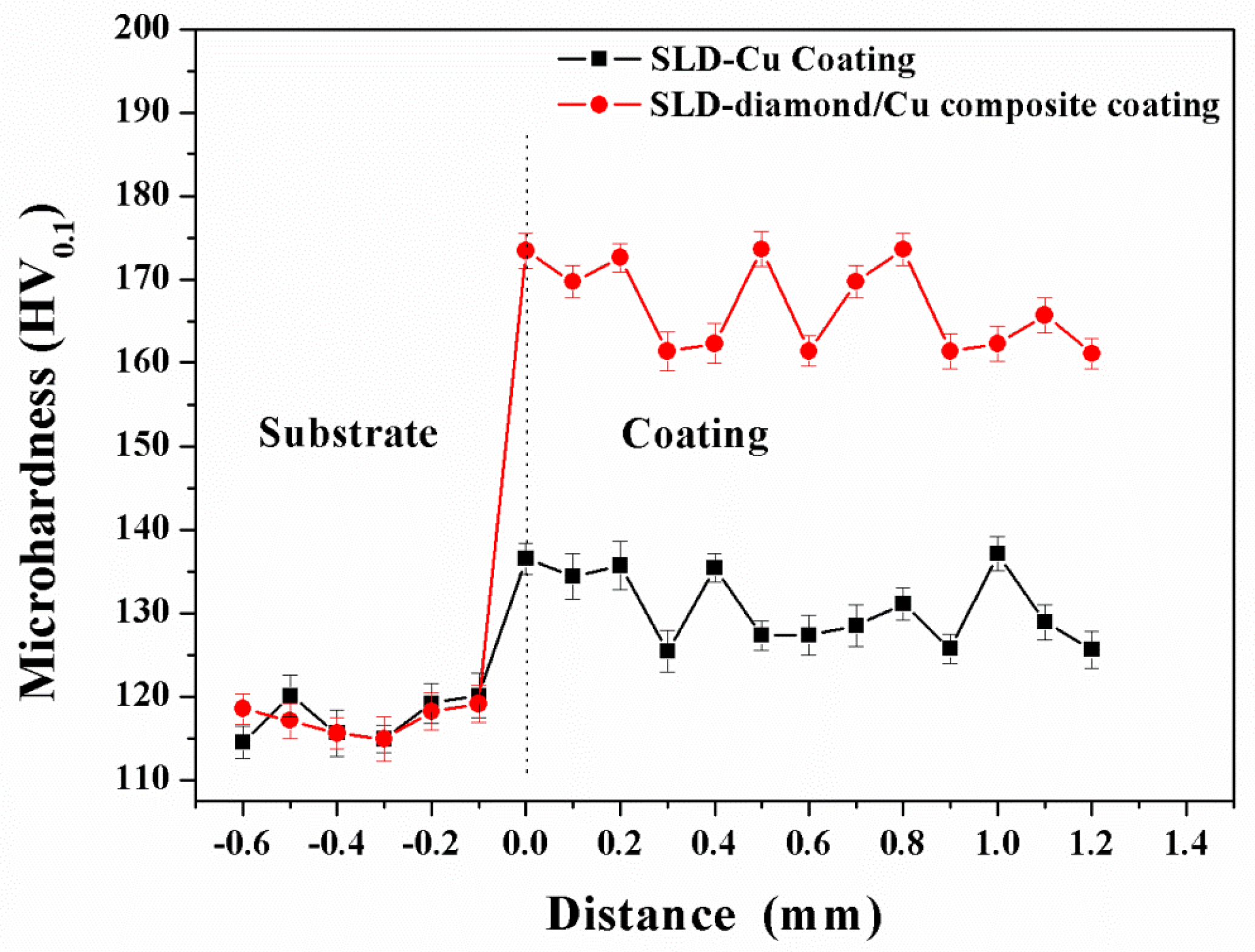
3.5. Micro-Hardness and Tribological Property

The micro-hardness variations of the SLD Cu and SLD diamond/Cu coatings through the coating layer are presented in Figure 12. Both the SLD Cu and SLD diamond/Cu coatings were prepared with the same laser power of 2 kW. The results show that the average hardness is 130 HV0.3 for the Cu coating and 165 HV0.3 for the diamond/Cu composite coating. However, it should be noted that the hardness of both coatings is not very consistent. This is because the hardness of the coatings was measured on a micro level from the coating surface to the substrate at a constant interval of 0.1 mm. Under such a condition, the indentation area may cover more or less diamond particles for the composite, which definitely influences the hardness value. Additionally, due to high hardness, diamond particles have a work hardening effect on deposited Cu particles during high velocity impact. As a result, the region away from diamond particles experienced less work hardening than those close to the diamond particles, which caused the hardness fluctuation of diamond/Cu coating.
Furthermore, it can be also found from Figure 12 that both coatings have higher hardness than the Cu substrate, which should result from the work hardening of Cu by high velocity impact of particles. The addition of diamond particles further increases the coating’s hardness which can be ascribed to their tamping effect during deposition because the extra kinetic energy of the hard diamond particles could promote the deformation of the metal particles. Moreover, the hardness of the Cu substrate (typically 70–80 HV) was increased up to around 115 HV (Cu coating) which can be attributed to the work hardening effect by high velocity impacting particles. During the SLD process, the surface of Cu substrate underwent plastic deformation to form effective bonding with the coating when high velocity particles impacted onto it. This plastic deformation would lead to work hardening of the thin surface.
The variations of friction coefficient with sliding time for SLD Cu and SLD diamond/Cu composite coating tested under the load of 6 N are illustrated in Figure 13. As demonstrated, the friction coefficient of the diamond/Cu coating is smaller and more stable than that of the Cu coating. The average friction coefficient of the diamond/Cu composite coating is about 0.55 after 60 min sliding, while that of the Cu coating is about 0.65 after the same sliding time. The wear rates were measured via dividing wear track volume by wear time and applied load. The wear rates of Cu and diamond/Cu coating were calculated to be 0.074 × 10⁻³ and 0.051 × 10⁻³ mm3/N·m, respectively, from the wear track volumes. The results of both friction coefficient and wear rate indicate that the introduction of diamond particulates did improve the tribological properties of the Cu coating. Yin et al. also found that diamond reinforcement significantly improved the trobological behavior of the CS Cu coating [19].
The differences in wear behavior between the coatings can be further understood by observation of the worn surface morphologies. As shown in Figure 14, under 6 N wear load, the wear track width of the diamond/Cu coating is about 624.2 μm, which is narrower than that of the Cu specimen (781.9 μm), further confirming the beneficial effect of diamond particles on the tribological performance of the Cu coating. Additionally, there are dark and light areas in the worn surface of the diamond/Cu coating, as illustrated in Figure 14c. EDS analysis was performed on these areas and the results of element concentrations are presented as inset in Figure 14c. It is shown that the dark area (area 1) contains a high content of O element; in contrast, a lower content of O element is detected in the light area (area 2). This suggests that oxidation had occurred in the worn track due to friction heat when the coating specimen was under the sliding wear, characterized by adhesive wear. In the meantime, it is also noted from Figure 14d that some diamond particles spalled off from the coating during sliding process and acted as abrasive media (abrasion wear), which caused grooves in the worn surface.
The worn surfaces of the Cu substrate and coating specimens from the tests under higher loads are shown in Figure 15. It can be seen that the wear track widths of all specimens increase with high loads. The Cu coating has the worst wear resistance under each load. Compared with the bulk Cu substrate, the Cu coating is less dense, which would lead to lower resistant ability for external invasion. The diamond/Cu composite shows superior load bearing capacity among all specimens for each wear test. 3D profilogram is a very useful method and has been extensively used to analyze wear surface and related mechanism [44]. The detailed elucidations of wear mechanism about SLD diamond/Cu composite coatings by this technology are currently carried out by us, and the results will be reported in subsequent papers.
According to Archard’s law of wear [45], there is a relationship between wear volume W, applied load L, sliding distance S and material hardness H (k is the wear coefficient) as described below:
W = k L × S H
In this study, the wear conditions including applied load and sliding distance were kept the same for both coatings. As the diamond/Cu coating has lower friction coefficient (Figure 13) and higher hardness (Figure 12) than the Cu coating, it should have a lower wear rate according to Archard’s law of wear.

4. Conclusions

The diamond/Cu composite coatings on Cu substrate were fabricated via the SLD process in a range of laser powers. The effects of laser irradiation on deposition efficiency, microstructure, interfacial bonding, phase composition, hardness, and wear-resistant property were investigated. The experimental results reveal that deposition efficiency of the SLD diamond/Cu composite coatings can be improved with increasing laser power initially, but higher laser power than 1.0 kW will not help. Diamond particles are uniformly dispersed into the composite coating, but the concentration of diamond particles shows no increase as laser power is varied. Due to the increase of velocity ratio and total energy by laser irradiation, the SLD composite coatings exhibit improved cohesive bonding compared to the CS counterpart. The adhesive bonding of the SLD composite coating is also enhanced because of substrate softening from laser heating. The SLD composite coating can retain the phase composition of the feedstock materials due to relatively low heat input. However, slight oxidation can also be detected for the coatings prepared under high laser power, which exerts adverse effects on particle deposition. For wear tests under different applied loads, the SLD diamond/Cu composite coating shows better tribological behavior benefiting from low friction coefficient, high hardness and uniform distribution of diamond particles.

Author Contributions

Q.Z. designed the research; L.W., G.Z., and B.L. conducted the experiments; L.W., G.Z., B.L., W.W., X.H., Z.C., G.D., Q.Z., and J.Y. discussed and analyzed the experimental results; L.W. wrote the manuscript; Q.Z., L.W., and B.L. revised the paper. All authors have read and agreed to the published version of the manuscript.

Funding

This research was funded by the National Natural Science Foundation of China (No. 51701182), the National Key R&D Program of China (No.2017YFB1103601), the Postdoctoral Research Program of China (2019M662103), and the 111 Project (No. 110000213920168001).

Acknowledgments

The authors would like to specially appreciate Rong Liu from Carlton University for her kind help with article revision.

Conflicts of Interest

The authors declare no conflict of interest.

References

  1. Wu, L.; Wang, W.; Li, B.; Chen, Z.; Jin, Y.; Yao, J. Influence of diamond particle size and content on the microstructure and properties of diamond/Cu composite coating prepared by supersonic laser deposition. Surf. Technol. 2019, 48, 40–46. (In Chinese) [Google Scholar]
  2. Zhang, X.; Lin, W.; Xu, M.; Cao, S.; Feng, Y.; Zhou, H. Addition of rare earth neodymium to improve interface of diamond/copper composites. Surf. Technol. 2018, 47, 27–32. (In Chinese) [Google Scholar]
  3. Das, P.; Paul, S.; Bandyopadhyay, P. HVOF sprayed diamond reinforced nano-structured bronze coatings. J. Alloy. Compd. 2018, 746, 361–369. [Google Scholar] [CrossRef]
  4. Venkateswarlu, K.; Ray, A.; Gunjan, M.; Mondal, D.; Pathak, L. Tribological wear behavior of diamond reinforced composite coating. Mater. Sci. Eng. A 2006, 418, 357–363. [Google Scholar] [CrossRef]
  5. Venkateswarlu, K.; Rajinikanth, V.; Naveen, T.; Sinba, D.; Ray, A. Abrasive wear behavior of thermally sprayed diamond reinforced composite coating deposited with both oxy-acetylene and HVOF techniques. Wear 2009, 266, 995–1002. [Google Scholar] [CrossRef]
  6. Das, P.; Paul, S.; Bandyopadhyay, P. Plasma sprayed diamond reinforced molybdenum coating. J. Alloy. Compd. 2018, 767, 448–455. [Google Scholar] [CrossRef]
  7. Das, P.; Paul, S.; Bandyopadhyay, P. Preparation of diamond reinforced metal powders as thermal spray feedstock using ball milling. Surf. Coat. Technol. 2016, 286, 165–171. [Google Scholar] [CrossRef]
  8. Sun, H.; Guo, M.; Meng, F.; Liu, A. Studies on hardfaced overlay of diamond grits reinforced Ni-Based alloy fabricated by laser cladding. Trans. Indian Inst. Met. 2016, 69, 1369–1376. [Google Scholar] [CrossRef]
  9. Iravani, M.; Khajepour, A.; Corbin, S.; Esmaeili, S. Pre-placed laser cladding of metal matrix diamond composite on mild steel. Surf. Coat. Technol. 2012, 206, 2089–2097. [Google Scholar] [CrossRef]
  10. Shao, W.; Ivanov, V.; Zhen, L.; Cui, Y.; Wang, Y. A study on graphitization of diamond in Cu–diamond composite materials. Mater. Lett. 2003, 58, 146–149. [Google Scholar] [CrossRef]
  11. Assadi, H.; Kreye, H.; Gärtner, F.; Klassen, T. Cold spraying—A materials perspective. Acta Mater. 2016, 116, 382–407. [Google Scholar] [CrossRef] [Green Version]
  12. Kwon, H.; Cho, S.; Kawasaki, A. Diamond-Reinforced Metal Matrix Bulk Materials Fabricated by a Low-Pressure Cold-Spray Process. Mater. Trans. 2015, 56, 108–112. [Google Scholar] [CrossRef] [Green Version]
  13. Li, W.; Zhang, D.; Huang, C.; Yin, S.; Yu, M.; Wang, F.; Liao, H. Modelling of impact behaviour of cold spray particles: Review. Surf. Eng. 2014, 30, 299–308. [Google Scholar] [CrossRef]
  14. Luo, X.; Li, C.; Shang, F.; Yang, G.; Wang, Y.; Li, C. High velocity impact induced microstructure evolution during deposition of cold spray coatings: A review. Surf. Coat. Technol. 2014, 254, 11–20. [Google Scholar] [CrossRef]
  15. Yin, S.; Wang, X.; Suo, X.; Liao, H.; Guo, Z.; Li, W.; Coddet, C. Deposition behavior of thermally softened Cu particles in cold spraying. Acta Mater. 2013, 61, 5105–5118. [Google Scholar] [CrossRef]
  16. Woo, D.; Heer, F.; Brewer, L.; Hooper, J.; Osswald, S. Synthesis of nanodiamond-reinforced aluminum metal matrix composites using cold-spray deposition. Carbon 2015, 86, 15–25. [Google Scholar] [CrossRef]
  17. Woo, D.; Sneed, B.; Peerally, F.; Heer, F.; Brewer, L.; Hooper, J.; Osswald, S. Synthesis of nanodiamond-reinforced aluminum metal composite powders and coatings using high-energy ball milling and cold spray. Carbon 2013, 63, 404–415. [Google Scholar] [CrossRef]
  18. Aldwell, B.; Yin, S.; Mcdonnell, K.; Trimble, D.; Hussain, T.; Lupoi, R. A novel method for metal–diamond composite coating deposition with cold spray and formation mechanism. Scr. Mater. 2016, 115, 10–13. [Google Scholar] [CrossRef]
  19. Yin, S.; Xie, Y.; Cizek, J.; Ekoi, E.; Hussain, T.; Dowling, D.; Lupoi, R. Advanced diamond-reinforced metal matrix composites via cold spray: Properties and deposition mechanism. Compos. Part B 2017, 113, 44–54. [Google Scholar] [CrossRef] [Green Version]
  20. Li, B.; Yao, J.; Zhang, Q.; Li, Z.; Yang, L. Microstructure and tribological performance of tungsten carbide reinforced stainless steel composite coatings by supersonic laser deposition. Surf. Coat. Technol. 2015, 275, 58–68. [Google Scholar] [CrossRef]
  21. Bray, M.; Cockburn, A.; O’Neill, W. The Laser-assisted Cold Spray process and deposit characterization. Surf. Coat. Technol. 2009, 203, 2851–2857. [Google Scholar] [CrossRef]
  22. Lupoi, R.; Sparkes, M.; Cockburn, A.; O’Neill, W. High speed titanium coatings by supersonic laser deposition. Mater. Lett. 2011, 65, 3205–3207. [Google Scholar] [CrossRef] [Green Version]
  23. Olakanmi, E. Optimization of the quality characteristics of laser-assisted cold-sprayed (LACS) aluminum coatings with Taguchi design of experiments (DOE). Mater. Manuf. Process. 2014, 31, 1490–1499. [Google Scholar] [CrossRef]
  24. Olakanmi, E.; Doyoyo, M. Laser-assisted cold-sprayed corrosion- and wear-resistant coatings: A review. J. Therm. Spray Technol. 2014, 23, 765–785. [Google Scholar] [CrossRef] [Green Version]
  25. Li, B.; Yang, L.; Li, Z.; Yao, J.; Zhang, Q.; Chen, Z.; Dong, G.; Wang, L. Beneficial Effects of Synchronous Laser Irradiation on the Characteristics of Cold-Sprayed Cu Coatings. J. Therm. Spray Technol. 2015, 24, 836–847. [Google Scholar] [CrossRef]
  26. Jones, M.; Cockburn, A.; Lupoi, R.; Sparkes, M.; O’Neill, W. Solid-state manufacturing of tungsten deposits onto molybdenum substrates with supersonic laser deposition. Mater. Lett. 2014, 134, 295–297. [Google Scholar] [CrossRef]
  27. Luo, F.; Cockburn, A.; Lupoi, R.; Sparkes, M.; O’Neill, W. Performance comparisonof Stellite 6 deposited on steel using supersonic laser deposition and lasercladding. Surf. Coat. Technol. 2012, 212, 119–127. [Google Scholar] [CrossRef]
  28. Li, B.; Jin, Y.; Yao, J.; Li, Z.; Zhang, Q.; Zhang, X. Influence of laser irradiation on deposition characteristics of cold sprayed Stellite-6 coatings. Opt. Laser Technol. 2018, 100, 27–39. [Google Scholar] [CrossRef]
  29. Yao, J.; Yang, L.; Li, B.; Li, Z. Characteristics and performance of hard Ni60 alloy coating produced with supersonic laser deposition technique. Mater. Des. 2015, 83, 26–35. [Google Scholar] [CrossRef]
  30. Yao, J.; Li, Z.; Li, B.; Yang, L. Characteristics and bonding behavior of Stellite 6 alloy coating processed with supersonic laser deposition. J. Alloy. Compd. 2016, 661, 526–534. [Google Scholar] [CrossRef]
  31. Lupoi, R.; Cockburn, A.; Bryan, C.; Sparkes, M.; Luo, F.; O’Neill, W. Hardfacing steel with nanostructured coatings of Stellite-6 by supersonic laser deposition. Light-Sci. Appl. 2012, 1, e10. [Google Scholar] [CrossRef] [Green Version]
  32. Birt, A.; Champagne, V.; Sisson, R.; Apelian, D. Statistically Guided Development of Laser-Assisted Cold Spray for Microstructural Control of Ti-6Al-4V. Metall. Mater. Trans. A 2017, 48, 1931–1943. [Google Scholar] [CrossRef]
  33. Yao, J.; Yang, L.; Li, B.; Li, Z. Beneficial effects of laser irradiation on the deposition process of diamond/Ni60 composite coating with cold spray. Appl. Surf. Sci. 2015, 330, 300–308. [Google Scholar] [CrossRef]
  34. Yang, L.; Li, B.; Yao, J.; Li, Z. Effects of diamond size on the deposition characteristic and tribological behavior of diamond/Ni60 composite coating prepared by supersonic laser deposition. Diam. Relat. Mater. 2015, 58, 139–148. [Google Scholar] [CrossRef]
  35. Li, B.; Jin, Y.; Yao, J.; Li, Z.; Zhang, Q. Solid-state fabrication of WCp-reinforced Stellite-6 composite coatings with supersonic laser deposition. Surf. Coat. Technol. 2017, 321, 386–396. [Google Scholar] [CrossRef]
  36. Assadi, H.; Gartner, F.; Stoltenhoff, T.; Kreye, H. Bonding mechanism in cold gas spraying. Acta Mater. 2003, 51, 4379–4394. [Google Scholar] [CrossRef]
  37. Assadi, H.; Schmidt, T.; Richter, H.; Kliemann, J.; Binder, K.; Gärtner, F.; Klassen, T.; Kreye, H. On parameter selection in cold spraying. J. Therm. Spray Technol. 2011, 20, 1161–1176. [Google Scholar] [CrossRef]
  38. Fukumoto, M.; Wada, H.; Tanade, K.; Yamada, M.; Yamaguchi, E.; Niwa, A.; Sugimoto, M.; Izawa, M. Effect of substrate temperature on deposition behavior of Cu particles on substrate surfaces in the cold spray process. J. Therm. Spray Technol. 2007, 16, 643–650. [Google Scholar] [CrossRef]
  39. Legoux, J.; Irissou, E.; Moreau, C. Effect of substrate temperature on the formation mechanism of cold-sprayed aluminum, zinc and tin coatings. J. Therm. Spray Technol. 2007, 16, 619–626. [Google Scholar] [CrossRef]
  40. Yin, S.; Wang, X.; Li, W.; Guo, X. Examination on substrate preheating process in cold gas dynamic spraying. J. Therm. Spray Technol. 2011, 20, 852–859. [Google Scholar] [CrossRef]
  41. Yu, M.; Li, W.; Wang, F.; Suo, X.; Liao, H. Effect of particle and substrate preheating on particle deformation behavior in cold spraying. Surf. Coat. Technol. 2013, 220, 174–178. [Google Scholar] [CrossRef]
  42. Ko, K.; Choi, J.; Lee, H.; Lee, B. Influence of oxide chemistry of feedstock on cold sprayed Cu coatings. Powder Technol. 2012, 218, 119–123. [Google Scholar] [CrossRef]
  43. Li, W.; Li, C.; Liao, H. Significant influence of particle surface oxidation on deposition efficiency, interface microstructure and adhesive strength of cold-sprayed Cu coatings. Appl. Surf. Sci. 2010, 256, 4953–4958. [Google Scholar] [CrossRef]
  44. Maruschak, P.; Panin, S.; Zakiev, I.; Poltaranin, M.; Sotnikov, A. Scale levels of damage to the raceway of a spherical roller bearing. Eng. Fail. Anal. 2016, 59, 69–78. [Google Scholar] [CrossRef]
  45. Archard, J. Properties of composite materials. J. Appl. Phys. 1953, 24, 981–988. [Google Scholar] [CrossRef]
Figure 1. Morphology and size distribution of the feedstock materials: (a,c) Cu powder; (b,d) diamond particles.
Coatings 10 00276 g001
Figure 2. SEM (a) and size distribution (b) of the ball-milled diamond/Cu composite powder.
Coatings 10 00276 g002
Figure 3. Schematic diagram of the SLD system.
Coatings 10 00276 g003
Figure 4. The variation of SLD diamond/Cu coating thickness with laser power: (a) 0 kW; (b) 0.5 kW; (c) 1.0 kW; (d) 1.5 kW; (e) 2.0 kW; (f) 2.5 kW.
Coatings 10 00276 g004aCoatings 10 00276 g004b
Figure 5. Cross-sectional microstructure of CS coating (a) and SLD coating prepared under 1.5 kW (b).
Coatings 10 00276 g005
Figure 6. The distribution and concentration of diamond particles in the composite coatings prepared under different laser powers: (a) 0.0 kW; (b) 0.5 kW; (c) 1.0 kW; (d) 1.5 kW; (e) 2.0 kW; (f) 2.5 kW.
Coatings 10 00276 g006aCoatings 10 00276 g006b
Figure 7. SEM images of CS (a) and SLD (b) coating showing bonding behavior between Cu matrix and diamond particles.
Coatings 10 00276 g007
Figure 8. Coating density comparison between (a) CS and (b) SLD coating.
Coatings 10 00276 g008
Figure 9. Coating/substrate interfacial bonding of (a) CS and (b) SLD coating.
Coatings 10 00276 g009
Figure 10. XRD patterns of feedstock powder, CS coating and SLD coating.
Coatings 10 00276 g010
Figure 11. EDS spectrum of the CS and SLD coatings.
Coatings 10 00276 g011
Figure 12. Hardness profiles of an SLD Cu and SLD diamond/Cu composite coating.
Coatings 10 00276 g012
Figure 13. Friction coefficient profiles of SLD Cu and SLD diamond/Cu coating.
Coatings 10 00276 g013
Figure 14. SEM image of worn surfaces from wear test under 6 N load: (a) SLD Cu coating and (bd) SLD diamond/Cu coating.
Coatings 10 00276 g014
Figure 15. SEM image of worn surface: (a) Cu substrate under 9 N wear load; (b) Cu substrate under 12 N wear load; (c) SLD Cu under 9 N wear load; (d) SLD Cu under 12 N wear load; (e) SLD diamond/Cu under 9 N wear load; (f) SLD diamond/Cu under 12 N wear load.
Coatings 10 00276 g015
Table 1. The experimental data for calculation of deposition efficiency.
Coatingm (g)t (s)Rf (g/min)Rd (g/min)DE (%)
CS1.164 ± 0.02364011.64 ± 0.2329.1 ± 0.58
SLD-0.5kW1.220 ± 0.01964012.20 ± 0.1930.5 ± 0.48
SLD-1.0 kW2.152 ± 0.03264021.52 ± 0.3253.8 ± 0.80
SLD-1.5 kW2.024 ± 0.02164020.24 ± 0.2150.6 ± 0.52
SLD-2.0 kW1.948 ± 0.01864019.48 ± 0.1848.7 ± 0.45
SLD-2.5 kW1.892 ± 0.01664018.92 ± 0.1647.3 ± 0.40

