Article

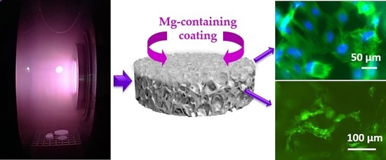
Plasma-Assisted Deposition of Magnesium-Containing Coatings on Porous Scaffolds for Bone Tissue Engineering

1
Department of Chemistry, University of Bari “Aldo Moro”, via Orabona 4, 70126 Bari, Italy
2
Institute of Nanotechnology (NANOTEC), National Research Council (CNR), c/o Department of Chemistry, University of Bari “Aldo Moro”, via Orabona 4, 70126 Bari, Italy
*
Author to whom correspondence should be addressed.
Coatings 2020, 10(4), 356; https://doi.org/10.3390/coatings10040356
Submission received: 19 March 2020 / Revised: 1 April 2020 / Accepted: 2 April 2020 / Published: 5 April 2020
(This article belongs to the Special Issue Plasma Polymerized Films for Biological Applications)

Abstract

:
Magnesium plays a pivotal role in the formation, growth, and repair of bone tissue; therefore, magnesium-based materials can be considered promising candidates for bone tissue engineering. This study aims to functionalize the surfaces of three-dimensional (3D) porous poly-ε caprolactone (PCL) scaffolds with magnesium-containing coatings using cold plasma-assisted deposition processes. For this purpose, the radiofrequency (RF) sputtering of a magnesium oxide target was carried out in a low-pressure plasma reactor using argon, water vapor, hydrogen, or mixtures of argon with one of the latter two options as the feed. Plasma processes produced significant differences in the chemical composition and wettability of the treated PCL samples, which are tightly related to the gas feed composition, as shown by X-ray photoelectron spectroscopy (XPS) and water contact angle (WCA) analyses. Cytocompatibility assays performed with Saos-2 osteoblast cells showed that deposited magnesium-containing thin films favor cell proliferation and adhesion on 3D scaffold surfaces, as well as cell colonization inside them. These films appear to be very promising for bone tissue regeneration.

Graphical Abstract

1. Introduction

Magnesium has vital functional roles in physiological systems. It is the fourth most abundant cation in the human body, with approximately half of its total content stored in bone tissue [1,2,3]. In particular, it is abundant in cartilage and bone tissue during the primary mineral phase formation and drastically decreases when the bone is mature. During this process, it inhibits the growth of calcium phosphate clusters and stabilizes the amorphous state of bone mineral apatite [4]. Several studies have demonstrated the stimulatory effects of magnesium on the formation, growth, and repair of bone tissue, making it interesting for bone tissue engineering [2,5,6].
Magnesium and its alloys were introduced as biocompatible, load-bearing, fracture-resistant, lightweight, and degradable material in orthopedic implants in the first half of the 20th century [2,3,7,8]. Indeed, in 1907, a plate of pure magnesium with gold-plated steel nails was used for the first time to repair a leg bone fracture [9]. The unfortunate complication of these materials is that they corrode too rapidly when introduced into the human physiological system, resulting in the loss of the implants’ mechanical integrity before the regeneration of bone tissue and production of hydrogen gas, at a rate that is too fast to be dealt with by the host tissue [2,3,8,10]. To overcome this problem, several strategies were investigated, such as the use of suitable alloying elements and protective coatings [3,11], even though it is very difficult to produce non-toxic and biocompatible materials [2,3,11].
In recent years, to obtain suitable orthopedic biomaterials to allow the full healing of bone defects before their complete degradation, studies have been carried out to combine magnesium-based materials with diverse biodegradable and biocompatible three dimensional (3D) porous scaffolds [1,4,5,6,12,13,14,15,16,17,18,19,20,21,22]. Scaffolds are supporting structural devices that can influence the behavior of cells in bone tissue regeneration processes [17,23,24,25]. In this way, cells adhere and grow properly when supported by their 3D network of interconnected pores and channels, allowing reconstruction of the anatomical shape of the tissue [26]. Ideally, scaffolds should be characterized by a surface chemistry suitable for cell attachment, proliferation, and differentiation, as well as the presence of mechanical properties matching those of the tissues at the site of implantation [23,24,25,27]. Thus, different typologies of magnesium-containing scaffolds were studied for bone tissue engineering: β-tricalcium phosphate (β-TCP) scaffolds decorated with gelatine containing magnesium [12]; scaffolds produced by freeze-drying [4], viscous mass foaming [5], cryogenic 3D printing, or sintering in the presence of magnesium-containing powders [13]; poly(lactic-co-glycolic acid) (PLGA)/TCP/magnesium scaffolds made by low-temperature rapid prototyping [1]; alginate scaffolds that incorporate bioactive glass particles containing Zn and Mg [14]; bioactive glass-based scaffolds coated with hydroxyapatite (HA) loaded with Mg and Zn [6]; and gelatine-, chitosan-, and magnesium-enriched montmorillonite scaffolds [15]. The use of a polymeric matrix is generally proposed as a solution to improve the mechanical properties of scaffolds. Among polymeric materials that can be utilized to realize these 3D porous temporary supports, poly-ε caprolactone (PCL) has recently drawn much attention [26,28]. It is a biodegradable polyester that attains a semi-crystalline rubbery state at physiological temperatures, resulting in high strength, elasticity, and elevated toughness. It is biocompatible, non-toxic, readily available, cost-effective, and is characterized by a degradation time lower than other polyesters in physiological conditions and its suitability for modification [28]. Its adjustable physicochemical state, biological properties, and mechanical strength allow it to withstand physical, chemical, and mechanical insults without significant loss of its properties. A PCL bone scaffold should be used as the 3D matrix framework that stimulates the attachment and proliferation of osteoinductive cells on its surfaces [25,26,28,29]. However, despite its valuable properties, PCL is not bioactive, eliciting possible inflammatory responses inside the host. It is also hydrophobic, adversely influencing cell adhesion and proliferation events [25,26,28,29]. For these reasons, specific investigations combining properties of PCL scaffolds with those of magnesium-based materials may represent a new avenue for bone tissue engineering [16,17,18,19,20]. In recent years, surface modification techniques have gained great importance for their ability to improve interactions of PCL with osteoconductive cells for the purpose of bone tissue regeneration [20,25,26].
Herein, cold plasma-assisted deposition processes were employed to functionalize the surface of 3D porous PCL scaffolds with magnesium-containing coatings. For decades, cold plasma processing has been proven as a unique, solvent-free, versatile technique to improve the surface properties of a variety of materials of any shape and thickness, without significantly change their bulk structures or features, particularly in life science applications [23,30]. Different types of cold plasma have been applied to tailor the surfaces of different biomaterials, helping in the first steps of the material–tissue integration processes, as well as helping to properly modify the surface composition of 3D scaffolds [25,26,29,31]. In the present study, the RF sputtering of a magnesium oxide target was carried out in a low-pressure plasma reactor fed by argon (Ar), water vapor (H2O), hydrogen (H2), or Ar/H2O as Ar/H2 mixtures. Two-dimensional (2D) flat substrates were also utilized to carefully investigate the effects of sputtering processes on the surface properties of PCL. Chemical and physical characterization of plasma-processed and native PCL samples as a function of the gas feed composition were performed through X-ray photoelectron spectroscopy (XPS) and water contact angle (WCA) analyses. The evaluation of the cytocompatibility improvement of scaffolds due to plasma deposition processes was assessed using viability and morphological assays of Saos-2 cells, which are frequently employed in experiments aiming to investigate osteocompatibility features of biomaterials.

2. Materials and Methods

2.1. PCL Sample Preparation

3D PCL porous scaffolds were prepared using the solvent casting/particulate leaching technique [23,31]. Briefly, a solution of PCL (Mn 70,000–90,000, Sigma-Aldrich, St. Louis, MI, USA) and chloroform (99.9% CHCl3, Sigma-Aldrich) at 20:80 wt/wt was combined with NaCl (Sigma-Aldrich) and PCL/NaCl 5:95 wt/wt, which was sieved beforehand to obtain crystals ranging between 150 and 300 µm. The obtained dough was cast in Teflon molds (10 mm diameter, 3 mm thickness), which were immersed in ethanol (Sigma-Aldrich) for 3 h to allow the solvent’s phase inversion process, and subsequently dipped in distilled water for 5 days to leach out the NaCl. The scaffolds produced in this way were finally dried at room temperature (RT). A mean porosity of 97% ± 3% was measured with an apparent density method, whereby the weight and volume of six different PCL scaffolds were measured; the apparent density, ρ* = m/V (g/cm3), was calculated; and the theoretical mean porosity (ϵ) was acquired using the following formula: ϵ = (1 − ρ*/ρ) × 100, in which ρ = 1.145 g/cm3 [23,26,32].
PCL 2D flat samples were produced using the spin-coating method. The polymer solution was prepared by mixing 1 g of PCL with 6 mL of CHCl3, and afterward this was deposited on polyethylene terephthalate (PET) substrates (10 mm diameter, 0.5 mm thickness, Goodfellow) using a Browser Science 200 spin-coater (2000 and 3200 rpm, 120 s). The resulting samples were immersed in ethanol for 3 h (phase inversion process) and dried at RT.

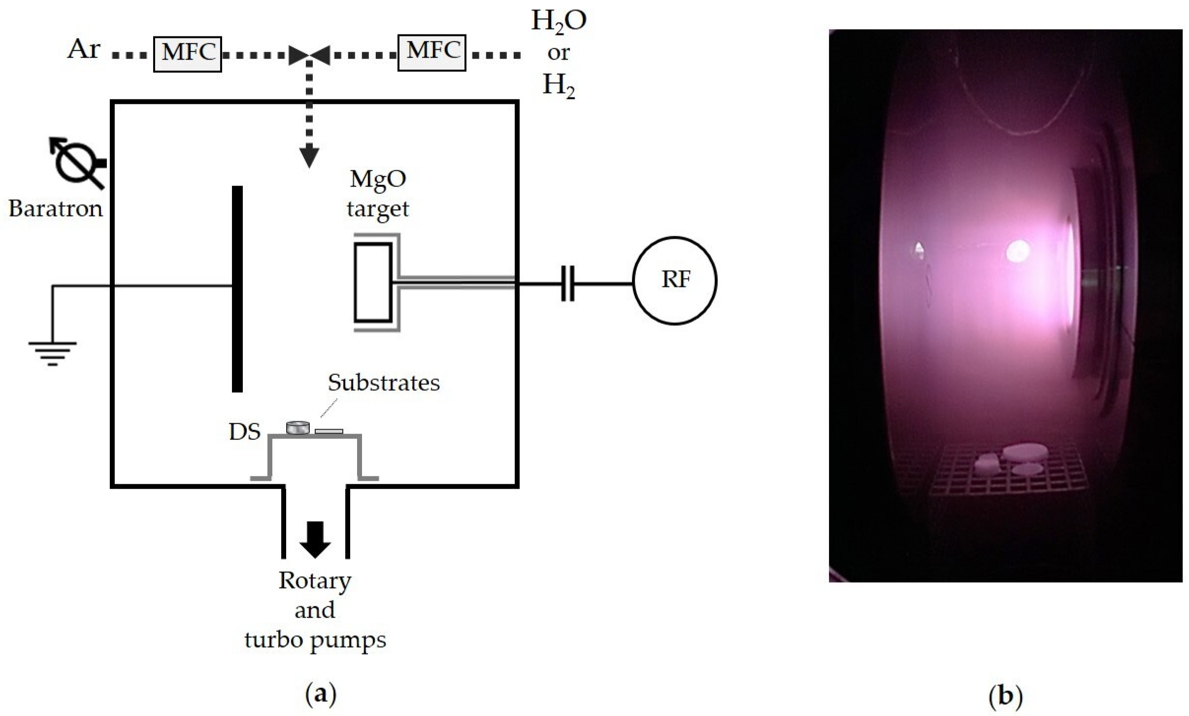
2.2. Plasma-Assisted Deposition of Magnesium-Containing Coatings

The plasma-assisted deposition processes were performed by radiofrequency (RF, 13.56 MHz) sputtering of a magnesium oxide target (MgO 99.9%, 68 mm diameter, 3 mm thickness, Goodfellow) in a stainless steel (SS) reactor with asymmetric vertical parallel plate electrodes (Figure 1) [26]. The largest and smallest electrodes (180 and 80 mm in diameter, respectively, with an interelectrode gap of 60 mm) were connected to ground (GND) and RF power supplies, respectively, through a matching network unit. The MgO sputtering target was located on the RF electrode [33].
Argon (Air Liquide, 99.95%), water vapor (double distilled water), hydrogen (RC-100 generator, CINEL Srl, Vigonza, Italy), or their mixture was used as the gas feed, with a total flow rate of 20 sccm. Specifically, the gas feed composition was varied as reported in Table 1, in which Φ H2O (%) and Φ H2 (%) are used to indicate the H2O and H2 percentage in the feed. Therefore, plasma processes performed using Ar as the feed correspond to Φ H2O 0% or Φ H2 0%; those carried out with H2O and H2 as the feeds correspond to Φ H2O 100% and Φ H2 100%, respectively; and those run with Ar/H2O and Ar/H2 mixtures correspond to Φ H2O and Φ H2 from 25% to 75%, respectively. A turbo-rotary pump system (Pfeiffer) was used to maintain the pressure at 50 mTorr, as monitored with a baratron (MKS Instruments, Andover, MA, USA). The input power value and the deposition time were kept constant at 50 W and 60 min, respectively.
PCL flat samples and scaffolds were located on a stainless steel grid placed downstream (DS) from the plasma zone (Figure 1), to avoid damage due to vacuum UV radiation, heating, and harsh sputtering conditions [26].

2.3. XPS Analyses

XPS analyses of PCL flat samples and scaffolds were carried out with a Theta Probe Thermo VG spectrometer equipped with a monochromatic Al Kα X-ray source (1486.6 eV, 300 µm X-ray spot, 300 W). Photoelectrons were collected at a take-off angle of 45° (sampling depth about 7 nm). An Ar flood gun (400 µA, 40 V) was applied during analyses for charge neutralization. Survey (range 0–1000 eV) and high-resolution (C 1s, O 1s, and Mg 2p) spectra were recorded at pass energy levels of 50 and 100 eV, respectively. The spectra charge correction was performed with the hydrocarbon C–C/C–H (binding energy, BE = 284.8 eV) component of the C 1s spectrum set as the reference. The surface atomic percentages of PCL samples, as well as the curve-fitting of C 1s and Mg 2p spectra of flat samples, were obtained with Avantage software. Four peaks were utilized for the C 1s curve-fitting of native substrates, centered at 284.8 ± 0.2 eV (C–C/C–H), 285.6 ± 0.2 eV (C–COOR/H, α carbon), 286.5 ± 0.2 eV (COR/H, ether/alcohol), and 289.0 ± 0.2 eV (COOR/H). A peak centered at 287.8 ± 0.2 eV (C=O/O–C–O) was added for plasma-modified substrates [23,26,34]. In order to assess if an increase of oxygen-containing (O-containing) functionalities occurs after plasma processing, the sum of the O-containing group (all the C 1s components, except that of C–C/C–H) percentages was calculated and then divided for the percentage of hydrocarbon peaks (νCO/CC). Two peaks were used for the Mg 2p curve-fitting, centered at 49.5 ± 0.2 eV (Mg and/or Mg(OH)2) and 50.8 ± 0.2 eV (MgO), respectively [35,36]. To chemically characterize the inner surfaces of 3D scaffolds, they were frozen in liquid N2 for 2 min and sliced perpendicularly to their top surface with a scalpel blade. Three different zones of the cross-sections per sample were then analyzed at various depths from the top (500 µm), center (1500), and bottom (3000) [26].

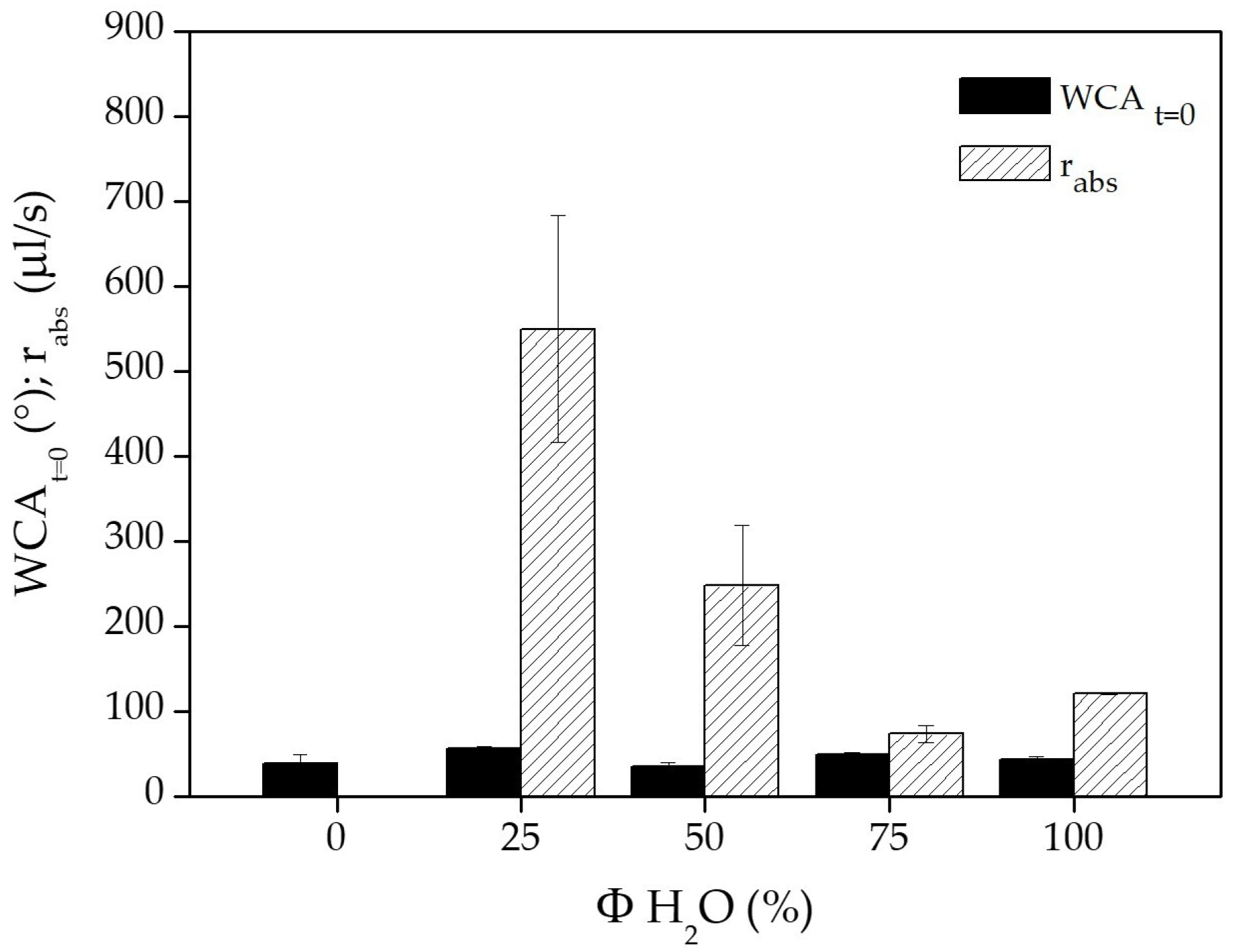
2.4. WCA Measurements

The wettability of PCL samples was determined by dynamic WCA measurements with a KSV CAM 200 instrument. A 1 μL drop of distilled water was placed on flat samples, its volume was increased, and then it was shrunk at a speed of 1 µL/s; 400 frames were recorded every 10 s. Advancing (θA) and receding (θR) angles were measured in this way, with θA representing the maximum angle observed during the increase of the drop and θR representing the angle just before the reduction of the sample–water contact surface [26]. The same procedure was utilized for scaffolds with a 3 µL drop. For certain scaffolds, the water absorption rate (rabs) and the WCA values at absorption time zero (WCAt = 0) were determined. An ultrafast camera was employed (800 frames, 2 ms interval frame, 420 frames per second); rabs values and WCAt = 0 were calculated by fitting the volume and WCA data, respectively, versus acquisition time with third-order polynomial curves [23,26]. Each reported data point is the average of five measurements performed on three different samples ± the standard deviation value.

2.5. Cytocompatibility Assays

The human osteoblastoma-derived Saos-2 cell line (ICLC, Genoa, Italy) was used for cell culture experiments on PCL scaffolds. Due to its reproducible and well-known behavior, the SAOS-2 osteoblast cell line was utilized in the present research. It is a model that is widely used in research related to the osteo-compatibility of materials. Cells were grown in Dulbecco’s modified Eagle’s medium (DMEM, Sigma-Aldrich) supplemented with 10% fetal bovine serum, 50 IU/mL streptomycin, 50 IU/mL penicillin, and 200 mmol/L glutamine (Sigma-Aldrich) at 37 °C in a saturated humid atmosphere of 5% CO2 and 95% air. Cells were detached with a Trypsin/EDTA solution (Sigma-Aldrich) and resuspended in the culture medium. To remove air from scaffolds pores, which causes floating of the light scaffolds in the medium within the wells, scaffolds were pre-wetted in the cell culture medium under vacuum. Subsequently, they were placed in 48-well plates and seeded with 5 × 10⁴ cells per scaffold in 0.5 mL of complete medium. Cells were observed after 17, 40, and 88 h of culture times.
The mitochondrial activity of Saos-2 cells was evaluated with the 3-(4,5-dimethyl thiazolyl-2)-2,5-diphenyltetrazolium bromide (MTT) colorimetric assay based on the conversion of 3-(4,5-dimethyl thiazolyl-2)-2,5-diphenyltetrazolium bromide (MTT, Sigma-Aldrich) to formazan [26]. After each culture period, for each sample, 100 µL of MTT solution (5 mg/mL) was added to the medium and left at 37 °C for 2 h to create formazan crystals, then dissolved in 1 mL of 10% Triton X-100 in isopropanol acid solution (Sigma-Aldrich). The optical densities (O.D.) of obtained solutions were acquired with a Jenway 6505 spectrophotometer at the wavelength of 570 nm (reference at 690 nm). This test was performed on three different samples of each type and at each considered time. Data were reported as histograms showing the means of the O.D. values ± the standard deviation value. Statistical analysis was carried out using two-way analysis of variance (ANOVA) followed by Bonferroni’s post-hoc test. Differences were considered statistically significant for p ˂ 0.05.
To observe cell morphology and scaffold colonization, the cell actin cytoskeleton was analyzed. At different cell culture times, cells were fixed with a solution of 4% formaldehyde in phosphate-buffered saline (PBS, Sigma-Aldrich) for 30 min, rinsed three times with PBS, permeabilized with PBS containing 0.1% Triton X-100 for 30 min, and after further washes with PBS, incubated with Atto488 phalloidin (Sigma-Aldrich) for at least 30 min. The ability of Atto488 phalloidin solution to perfuse through the scaffold structure allowed investigation of the cell colonization within these supports after sectioning them horizontally (i.e., 1500 µm from the top) with a scalpel blade. To observe cell nuclei, a drop of Fluoroshield containing 4,6-diamidine-2-phenylindole dihydrochloride (DAPI; Sigma-Aldrich, St. Louis, Missouri, U.S. ) was added to each scaffold. Stained cells, on the surface and within the scaffold, were examined with a Zeiss Axiomat microscope (Zeiss, Oberkochen, Germany). Axio Vision software was utilized to acquire images.

3. Results and Discussion

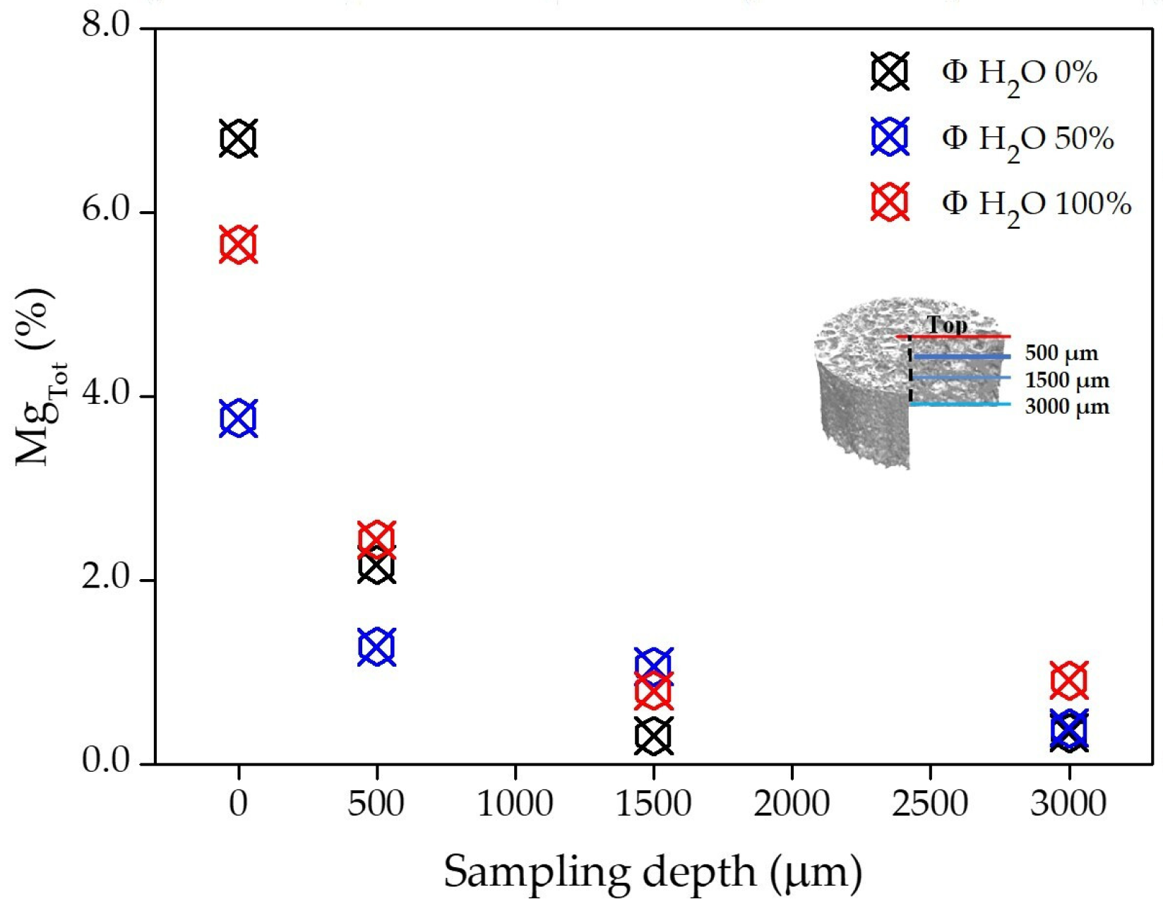
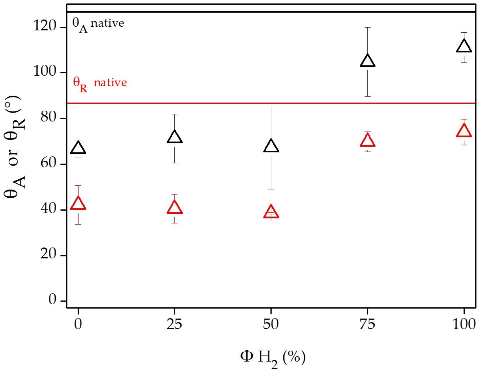
3.1. Chemical and Physical Characterization of PCL Flat Samples and Scaffolds

The surface chemical composition of PCL flat samples and scaffolds was analyzed by XPS. In Table 2, the surface atomic concentrations of both types of native and plasma-modified samples is reported as a function of the feed composition. The 2D flat samples were used to disentangle the effect of the chemical composition of deposited coatings from that of the underlying scaffold topography. In fact, the surface heterogeneity of porous materials can significantly influence XPS analyses due to the alternation of peaks and valleys (i.e., different sampling depth), increasing the difficult distinction between the deposited coatings and the underlying substrate, especially when the thickness of thin films is low, as in this case (~60 nm) [26].
As expected, the elemental composition of native PCL substrates was different from that of plasma-treated ones, characterized by the presence of magnesium in addition to carbon and oxygen. As better illustrated in Figure 2, the surface magnesium percentage, indicated as MgTot %, of flat samples is influenced by the feed composition. It decreases in relation to the H2O content in the feed, and increases with the H2 content; thus, samples modified using H2O (Φ H2O 100%) and H2 (Φ H2 100%) as feed show the lowest and highest MgTot %, respectively. The presence of carbon on plasma-processed substrates is ascribable to the underlying polymeric PCL, probably due to a non-uniform coverage of its surface or to coatings that are thinner than the sampling depth of the XPS. However, organic contaminations originating during or after the plasma functionalization cannot be excluded. The carbon percentage is lowest for samples with the highest magnesium atomic concentration. Results in agreement with those just mentioned can also be observed for 3D porous scaffolds (Table 2); a lower magnesium content in comparison with the corresponding flat samples can be noted, which is closely related to the analytical problems that the morphology and structure of these porous samples can cause. The different outcomes obtained by varying the feed composition are attributable to the impact of the latter on the RF sputter process from the MgO target, which is known to affect the sputtering yield [37,38,39,40,41]. It is possible to conclude that under the experimental conditions used in this work, H2O feed shows a lower capacity than Ar and Ar/H2O to sputter Mg from the target, while the H2 feed exhibits a higher ability to sputter the same material compared with Ar and Ar/H2 mixtures. These findings are confirmed by both the increase of the magnesium content and the decrease of the carbon content, which attest to the better coating of H2 samples with a magnesium-containing layer. Thus, H2O and H2 feeds achieved the lowest and highest ablation, respectively, from the MgO target during cold plasma RF sputtering processes. In order to explain these findings, possible involvement of these two gases has been supposed. It is well-known that the sputtering of a target by a non-reactive gas such as Ar proceeds through a multistep sequence, as follows: (1) an energetic particle (e.g., ion) is impinged on a target; (2) momentum and energy are transferred to the atoms on the target’s surface; (3) a collision cascade is initiated in the bulk of the target if the energy gained by the surface atoms exceeds their displacement energy; (4) the target atom is ejected if the energy gained by the latter exceeds its binding energy with its surface counterparts. When a reactive gas (i.e., H2O or H2) is added to the non-reactive one, the former not only reacts with the substrate, but also with the target. At typical sputtering working pressures, a reaction of the reactive gas directly on the target is expected. When the reactive gas flow is high (in our case >25% of the total flow), a critical flow is reached. At this critical flow, the metallic particles cannot consume all the reactive gas, so they stay in the gas phase, promoting other reactions at gas–material interfaces. When the reactive gas is H2O, it can react with the MgO target by promoting enrichment of the target with oxygen. As a result, a decrease in the sputter rate can occur because the binding energy of the compounds is much higher than that of pure metals. On the contrary, when H2 is used as a reactive gas, it can promote the etching of the oxygen present on the target and the formation of metallic Mg, which can be easily sputtered due to its higher sputter rate compared to MgO [37,38,39,40,41]. In fact, after the sputtering process performed with H2, the color of the target’s surface turns grayish, which is indicative of the formation of metallic Mg.
In Figure 3, the ratio between the contributions of the peak centered at 49.5 ± 0.2 eV (Mg or Mg(OH)2), indicated as XMg, and of the one centered at 50.8 ± 0.2 eV (MgO), resulting from the Mg 2p curve-fitting, are reported as a function of the gas feed composition. Regardless of the type of gas feed used, the XMg/MgO ratio is around one, except for samples prepared with Φ H2O 100% and Φ H2 100%. Some examples of the best fitting of the Mg 2p spectra acquired for these last two samples are shown in Figure S1. This experimental evidence proves the formation of Mg or Mg(OH)2 components during plasma processes, which is arguably due to the generation of active species in the plasma [36]. The XMg and MgO values for samples treated using H2 and H2O as feeds are the highest and lowest, respectively. Due to the high reactivity of elemental magnesium in air, it is expected that it contributes very little to XMg, which is mainly attributable to the Mg(OH)2 compound. The presence of the latter is desirable for applications of materials in bone tissue engineering. Since it induces anti-inflammatory abilities, enhances bone growth in vivo, and increases the osteoblast activity via the decrease of the osteoclast’s peri-implant bone remodelling [17,22,42].
As reported in Table 3 and Figure S2, the different gas feeds used during the plasma processes affect the chemical composition of the organic part of the treated materials. After plasma treatment, an increase in the ratio between O-containing groups and hydrocarbon ones (νCO/CC) can be observed. The presence of H2O in the gas feed dramatically increases the νCO/CC value, while a slight decrease of this ratio with the increase of the H2 content in the feed can be noticed. Based on the obtained results, it can be assessed that the different components of the gas feed, in addition to affect the sputtering process, promote other chemical or physical reactions at the gas–material interfaces, as follows: H2O vapor mainly produces a grafting of O-containing groups; through physical sputtering, Ar mainly promotes the breakage of chemical bonds that are subsequently saturated by post-treatment exposure of the material to air; H2 mainly acts as an agent that terminates the radical reaction initiated by the sputtering of the substrate or induces chemical sputtering (plasma etching) of hydrocarbon functionalities and O–containing functionalities (i.e., the formation of CH4 or H2O), reducing the content of O–containing polar groups.
To verify whether plasma deposition processes can create chemical functionalization gradients from the top to the inside surfaces of 3D porous scaffolds, preliminary XPS analyses were performed on their cross-sections at different distances from the top, as described in the Materials and Methods section. As represented in Figure 4, the magnesium concentration decreases from the top to the bottom (3000 µm deep) of the scaffolds, with higher density on the internal surfaces at 500 µm depth. Moreover, by looking at the C 1s spectra in Figure S3, it is possible to observe that for PCL scaffolds treated with Φ H2 100% (Figure S3a), going from the top to the inner part, the broadening of the spectrum after 500 µm is reduced and the C 1s peaks are similar to those of native samples; for scaffolds treated with Φ H2O 100% (Figure S3b), the C 1s spectra are broader than those of native ones, supporting the modification of the whole scaffold with O–containing moieties. Thus, it can be partially concluded that active species generated in the RF sputtering experiments can penetrate inside the 3D samples to a depth of about 500 µm. A possible improvement of cell colonization is, therefore, expected not only on their external surfaces but also across them, because of the O–containing functionalities presence [25,26].
WCA measurements demonstrate that plasma processes affect the wettability of PCL substrates. Indeed, as shown in Figure S4, treated flat samples are characterized by lower θA and θR WCAs than the native hydrophobic ones. These effects are less relevant for samples treated using Ar, Ar/H2, or H2 as the feed, which are characterized by higher and lower magnesium content and fraction of O–containing groups (νCO/CC, Table 3), respectively, than in samples processed with Ar/H2O or H2O as the feed. The latter ones show a noticeable decrease of θA and θR WCAs. This experimental evidence suggests that the presence of magnesium-containing coatings reduces the hydrophobicity of PCL surfaces, as well as suggesting that the use of H2O vapor during sputtering processes facilitates the development of highly hydrophilic PCL flat surfaces, through the formation of polar O–containing moieties which increases the νCO/CC value of Table 3 [23,26]. These findings were also confirmed with PCL scaffolds. These were treated with Ar, Ar/H2, or H2 feeds, showing a decrease of θA and θR WCA values compared to native substrates (Figure 5), although this was less evident for 3D samples modified with 75% H2 in the feed or with H2 only. This is attributable to the ability of H2 to promote the etching of O-containing groups or to the high magnesium content found in such samples. Scaffolds treated using Ar/H2O or H2O as the feed absorb water due to their highly hydrophilic character, which is in good agreement with their functionalization with O–containing groups. For this reason, better cell adhesion and colonization properties are expected for these samples compared to those treated using H2 [26,29,31,43,44].
As displayed in Figure 6, for all scaffolds treated with Ar/H2O mixtures or H2O feed, the WCA values at absorption time zero are comparable, while the water absorption rate decreases as the H2O concentration increases in the Ar/H2O mixtures. A clear connection between this trend and the surface chemical composition of the scaffold is not apparent, suggesting that it could be ascribable to the very complex topography of the porous supports, which may affect their surface plasma functionalization, thereby affecting their capacity to absorb water.

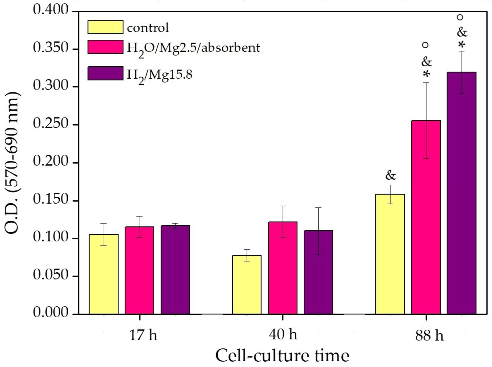
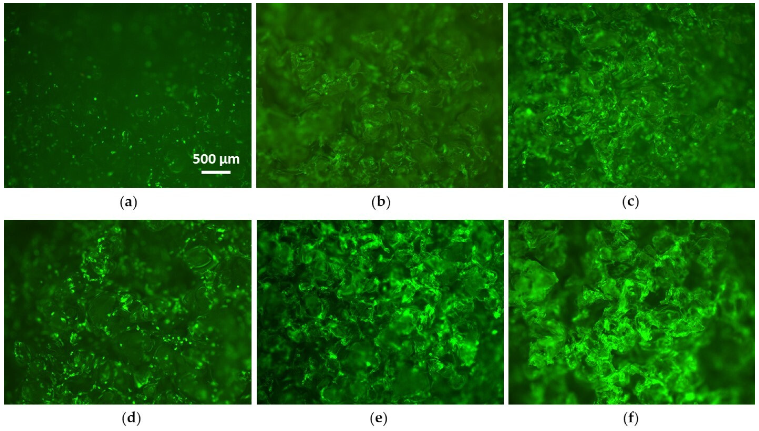
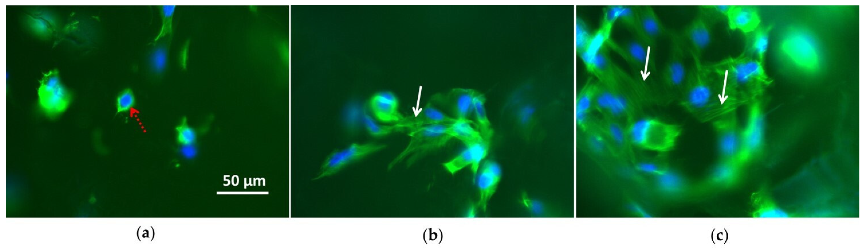
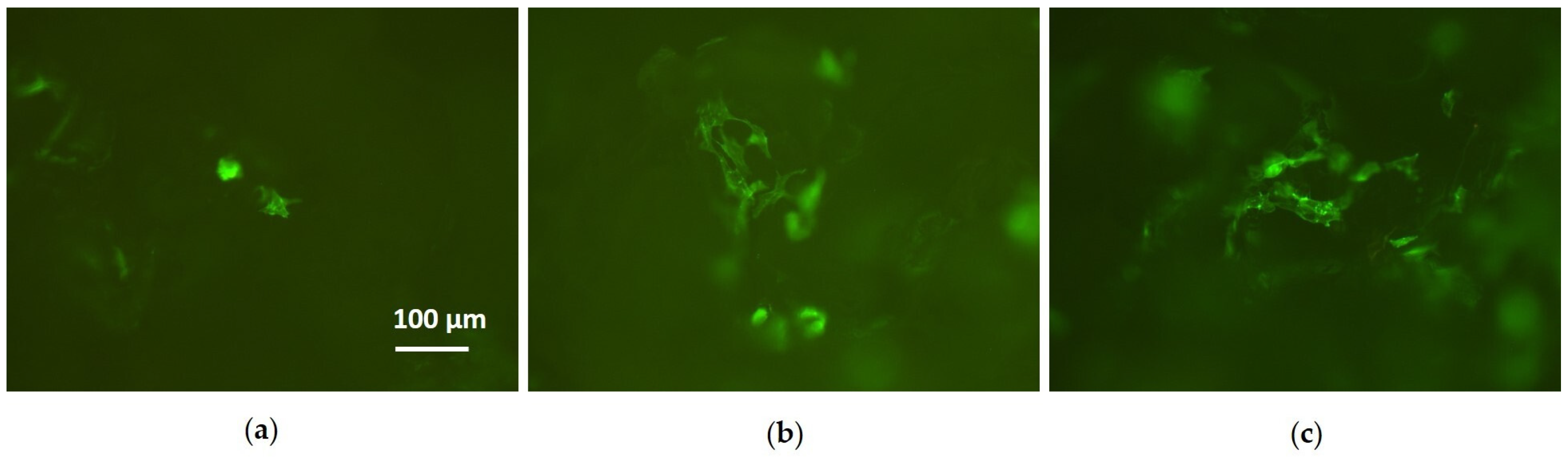
3.2. Cell Culture Tests

PCL scaffolds plasma-processed with Φ H2O 100% and Φ H2 100%, as well as native ones, were chosen to perform the cytocompatibility assays with Saos-2 osteoblast cells. Indeed, according to the chemical and physical characterization results, these scaffolds present the most marked differences. Particularly, native 3D porous substrates are composed entirely of PCL and are hydrophobic (θA = 129 ± 3°, θR = 88 ± 1°); while plasma-treated using H2O as the feed are characterized by a low surface magnesium content (2.5 ± 0.1%), are extremely hydrophilic, and absorb water. Those modified using H2 as the feed present a very high surface magnesium content (15.8 ± 0.7%) and are less hydrophobic (θA = 111 ± 7°, θR = 74 ± 6°) than native scaffolds, but cannot absorb water.
To indicate the different samples in a simplified way, in the next part of this report they will be named as follows:
1)
Control—native 3D PCL porous scaffolds;
2)
H2O/Mg2.5/absorbent—3D PCL porous scaffolds processed with Φ H2O 100%;
3)
H2/Mg15.8—3D PCL porous scaffolds processed with Φ H2 100%.
In Figure 7, the viability data obtained for Saos-2 cells grown on the three types of scaffolds with different culture times (17, 40, and 88 h) are reported. This can be attributed to the fact that the MTT values are too low to be able to perceive a difference in cell viability on different scaffolds. As it is reported from the morphological analysis shown further on in the paper, the same differences in cell behavior can be observed—from a morphological point of view—among the adhesion results on 3D scaffolds. Moreover, no growth can be observed in any sample for Saos-2 cells after 17 and 40 h. The absence of statistically significant growth, which was also true for control samples, means that no difference in Saos2 viability can be attributed to differences in the chemical compositions of the scaffolds in this time-span. In contrast, after 88 h, cell proliferation occurs in all samples. Moreover, cells grown for 88 h on H2O/Mg2.5/absorbent and H2/Mg15.8 scaffolds exhibit greater metabolic activity than those seeded on controls (p ˂ 0.05). This phenomenon is ascribable to the very high hydrophilic character of samples treated with H2O as the feed [23,26,29,31,44]. It also suggests that the presence of magnesium-containing coatings on the scaffolds favors their cytocompatibility: these samples are hydrophobic but have the highest magnesium content.
Since cell viability assay cannot show morphological changes in cell behavior (which is achievable only with microscopic observation of cells), the Saos-2 actin cytoskeleton was observed with fluorescence microscopy. The cells’ morphological features were examined, as well as the colonization of the scaffolds at different culture times. The images in Figure 8, which are representative of cells on control, H2O/Mg2.5/absorbent, and H2/Mg15.8 PCL scaffolds, show how cells behave on the external surface of the scaffolds after 17 and 88 h of growth. When comparing the presence of bright green surface spots after 17 h and 88 h, cell proliferation clearly occurs, which is proven by the increase of brightness. This effect is more emphasized for H2/Mg15.8 scaffolds and less emphasized for control. Images acquired at higher magnification, as shown in Figure 9, clearly reveal the cell morphology. Isolated and non-spread cells—characterized by round morphology without actin stress fibers, which are indicative of weak cell adhesion [23,25,29,45]—are displayed on control samples. On plasma-modified substrates, on the contrary, clusters of cells are evident, as well as the presence of actin stress fibers, highlighting a spreading morphology. This is indicative of good interaction of cells with surfaces and the good health of the Saos-2 cells in an active state of adhesion [23,25,29,46].
To investigate details of the cell colonization within the 3D porous scaffolds, these were sectioned horizontally after 88 h of growth, as described in the Materials and Methods section, and analyzed with fluorescence microscopy. As illustrated in Figure 10, the morphology of Saos-2 cells within the three typologies of scaffolds reflects the findings from their surfaces. Indeed, very few round single cells can be observed on the control sections, while favorable clustered and spread cells can be noted on sections of H2O/Mg2.5/absorbent and H2/Mg15.8 samples.
These results confirm that plasma-deposited magnesium-containing thin films improve the compatibility of the entire PCL scaffold surface with Saos-2 cells; cell in-growth is dramatically promoted, which is very promising for bone tissue engineering [26]. In addition to the presence of the magnesium-containing coating, the enhanced surface cell adhesion and colonization within the 3D porous networks for H2O/Mg2.5/absorbent samples is ascribable to the marked increase of wettability. For the H2/Mg15.8 samples that are (in principle) not hydrophilic enough to promote interaction with cells [25,29,44], the enhanced cell adhesion and colonization could be attributed to the high magnesium content on the top surface, which could also cause cells to colonize the scaffold’s core.

4. Conclusions

Magnesium-containing coatings were deposited on PCL substrates using low-pressure RF sputtering of a MgO target in a properly configured plasma reactor fed with Ar, H2O, H2, or Ar/H2O as Ar/H2 mixtures. XPS analyses and WCA measurements allowed assessment of the efficacy of the plasma processes, as well as investigation of their effects on the surface chemical composition and wettability of PCL samples as functions of the feed composition. The higher capacity of H2 than H2O to sputter the MgO target to deposit magnesium-containing coatings and the creation of highly hydrophilic surfaces due to the use of H2O during plasma processes were demonstrated. The most marked differences were observed between substrates modified using H2O and H2 as the feeds. Scaffolds treated with H2O were had the lowest magnesium content and were able to absorb water; on the contrary, those treated with H2 had the highest magnesium percentage and were less hydrophobic than native ones, but were not absorbent.
Cell compatibility assays proved that the surface functionalization of the PCL scaffolds with magnesium-containing thin films enhances Saos-2 cell proliferation and adhesion. It also promotes colonization within their 3D porous networks, which is favorable for bone tissue engineering.

Supplementary Materials

The following are available online at https://www.mdpi.com/2079-6412/10/4/356/s1, Figure S1: Curve-fitting of XPS high-resolution Mg 2p spectra of flat PCL samples treated with Φ H2O 100% and Φ H2 100% fed plasma, Figure S2: Curve-fitting of XPS high-resolution C 1s spectra of native and plasma-processed PCL flat samples with Φ H2O 100% and Φ H2 100%, Figure S3: Overlap of XPS C 1s high-resolution spectra acquired at different sampling depths from the top of PCL scaffolds treated with Φ H2 100% and Φ H2O 100%, Figure S4: Advancing and receding WCAs of PCL flat samples as functions of the feed composition.

Author Contributions

Conceptualization, E.S. and R.G.; methodology, V.A.; software, S.C.; validation, E.S., V.A., and R.G.; investigation, V.A., E.S., and R.G.; resources, P.F. and F.F.; data curation, E.S., R.G., V.A., and S.C.; writing—original draft preparation, V.A.; writing—review and editing, E.S., R.G., and P.F.; supervision, E.S.; project administration, E.S. and P.F.; funding acquisition, P.F. and F.F. All authors have read and agreed to the published version of the manuscript.

Funding

This research was funded by Italian Ministry for Education (MIUR), under grant PONa3_00369 SISTEMA, Laboratorio Pubblico di Ricerca Industriale Pugliese dei Plasmi (LIPP), Rete di Laboratorio 51), and RINOVATIS, grant number: 02 00563 3448479.

Acknowledgments

Danilo Benedetti is gratefully acknowledged for his technical support and Emiliano Altamura is gratefully acknowledged for the constructive scientific discussion around characterization by means of fluorescence microscopy.

Conflicts of Interest

The authors declare no conflict of interest. The funders had no role in the design of the study; in the collection, analyses, or interpretation of data; in the writing of the manuscript, or in the decision to publish the results.

References

  1. Lai, Y.; Li, Y.; Cao, H.; Long, J.; Wang, X.; Li, L.; Li, C.; Jia, Q.; Teng, B.; Tang, T.; et al. Osteogenic magnesium incorporated into PLGA/TCP porous scaffold by 3D printing for repairing challenging bone defect. Biomaterials 2019, 197, 207–219. [Google Scholar] [CrossRef] [PubMed]
  2. Staiger, M.P.; Pietak, A.M.; Huadmai, J.; Dias, G. Magnesium and its alloys as orthopedic biomaterials: A review. Biomaterials 2006, 27, 1728–1734. [Google Scholar] [CrossRef] [PubMed]
  3. Li, N.; Zheng, Y. Novel Magnesium Alloys Developed for Biomedical Application: A Review. J. Mater. Sci. Technol. 2013, 29, 489–502. [Google Scholar] [CrossRef]
  4. Craciunescu, O.; Tardei, C.; Moldovan, L.; Zarnescu, O. Magnesium substitution effect on porous scaffolds for bone repair. Cent. Eur. J. Biol. 2011, 6, 301–311. [Google Scholar] [CrossRef]
  5. Salma-Ancane, K.; Stipniece, L.; Putnins, A.; Berzina-Cimdina, L. Development of Mg-containing porous β-tricalcium phosphate scaffolds for bone repair. Ceram. Int. 2015, 41, 4996–5004. [Google Scholar] [CrossRef]
  6. Dittler, M.L.; Unalan, I.; Grünewald, A.; Beltrán, A.M.; Grillo, C.A.; Destch, R.; Gonzalez, M.C.; Boccaccini, A.R. Bioactive glass (45S5)-based 3D scaffolds coated with magnesium and zinc loadedhydroxyapatite nanoparticles for tissue engineering applications. Colloids Surf. B Biointerfaces 2019, 182, 110346–110355. [Google Scholar] [CrossRef]
  7. Witte, F. The history of biodegradable magnesium implants: A review. Acta Biomater. 2010, 6, 1680–1692. [Google Scholar] [CrossRef]
  8. Poinern, G.E.J.; Brundavanam, S.; Fawcett, D. Biomedical Magnesium Alloys: A Review of Material Properties, Surface Modifications and Potential as a Biodegradable Orthopaedic Implant. Am. J. Biomed. Eng. 2012, 2, 218–240. [Google Scholar] [CrossRef] [Green Version]
  9. Lambotte, A. L’utilisation du magnesium comme material perdu dans l’osteosynthese. Bull. Mem. Soc. Nat. Chir. 1932, 28, 1325–1334. [Google Scholar]
  10. Kirkland, N.T.; Birbilis, N.; Staiger, M.P. Assessing the corrosion of biodegradable magnesium implants: A critical review of current methodologies and their limitations. Acta Biomater. 2012, 8, 925–936. [Google Scholar] [CrossRef]
  11. Yang, J.; Cui, F.; Lee, I.S. Surface Modifications of Magnesium Alloys for Biomedical Applications. Ann. Biomed. Eng. 2011, 39, 1857–1871. [Google Scholar] [CrossRef] [PubMed]
  12. Golzar, H.; Mohammadrezaei, D.; Yadegari, A.; Rasoulianboroujeni, M.; Hashemi, M.; Omidi, M.; Yazdian, F.; Shalbaf, M.; Tayebi, L. Incorporation of functionalized reduced graphene oxide/magnesium nanohybrid to enhance the osteoinductivity capability of 3D printed calcium phosphate-based scaffolds. Compos. Part B 2020, 185, 107749–107759. [Google Scholar] [CrossRef]
  13. Gu, Y.; Zhang, J.; Zhang, X.; Liang, G.; Xu, T.; Niu, W. Three-dimensional Printed Mg-Doped b-TCP Bone Tissue Engineering Scaffolds: Effects of Magnesium Ion Concentration on Osteogenesis and Angiogenesis In Vitro. Tissue Eng. Regen. Med. 2019, 16, 415–429. [Google Scholar] [CrossRef]
  14. Zamani, D.; Moztarzadeh, F.; Bizari, D. Alginate-bioactive glass containing Zn and Mg composite scaffolds for bone tissue engineering. Ann. Biomed. Eng. 2019, 137, 1256–1267. [Google Scholar] [CrossRef] [PubMed]
  15. Demir, A.K. Development and characterization of gelatin/chitosan/montmorillonite composite scaffold enriched with magnesium. Rev. Roum. Chim. 2019, 64, 327–334. [Google Scholar] [CrossRef]
  16. Baradaran, T.; Shafiei, S.S.; Mohammadi, S.; Moztarzadeh, F. Poly (ε-caprolactone)/layered double hydroxide microspheres-aggregated nanocomposite scaffold for osteogenic differentiation of mesenchymal stem cell. Mater. Today Commun. 2020, 23, 100913–100924. [Google Scholar] [CrossRef]
  17. Kim, K.J.; Choi, S.; Cho, Y.S.; Yang, S.J.; Cho, Y.S.; Kim, K.K. Magnesium ions enhance infiltration of osteoblasts in scaffolds via increasing cell motility. Mater. Sci: Mater. Med. 2017, 28, 96. [Google Scholar] [CrossRef]
  18. Perumal, G.; Sivakumar, P.M.; Nandkumar, A.M.; Doble, M. Synthesis of magnesium phosphate nanoflakes and its PCL composite electrospun nanofiber scaffolds for bone tissue regeneration. Mater. Sci. Eng. C 2020, 109, 110527–110537. [Google Scholar] [CrossRef]
  19. Roh, H.S.; Lee, C.M.; Hwang, Y.H.; Kook, M.S.; Yang, S.W.; Lee, D.; Kim, B.H. Addition of MgO nanoparticles and plasma surface treatment of three-dimensional printed polycaprolactone/hydroxyapatite scaffolds for improving bone regeneration. Mater. Sci. Eng. C 2017, 74, 525–535. [Google Scholar] [CrossRef]
  20. Vandrovcova, M.; Douglas, T.E.L.; Mróz, W.; Musial, O.; Schaubroeck, D.; Budner, B.; Syroka, R.; Dubruel, P.; Bacakova, L. Pulsed laser deposition of magnesium-doped calcium phosphate coatings on porous polycaprolactone scaffolds produced by rapid prototyping. Mater. Lett. 2015, 148, 178–183. [Google Scholar] [CrossRef]
  21. Shen, J.; Wang, W.; Zhai, X.; Chen, B.; Qiao, W.; Li, W.; Li, P.; Zhao, Y.; Meng, Y.; Qian, S.; et al. 3D-printed nanocomposite scaffolds with tunable magnesium ionic microenvironment induce in situ bone tissue regeneration. Appl. Mater. Today 2019, 16, 493–507. [Google Scholar] [CrossRef]
  22. Go, E.Z.; Kang, E.Y.; Lee, S.K.; Park, S.; Kim, J.H.; Park, W.; Kim, I.W.; Choi, B.; Han, D.K. An osteoconductive PLGA scaffold with bioactive β-TCP and anti-inflammatory Mg(OH)2 to improve in vivo bone regeneration. Biomater. Sci. 2020. [Google Scholar] [CrossRef] [PubMed]
  23. Sardella, E.; Fisher, E.R.; Shearer, J.C.; Garzia Trulli, M.; Gristina, R.; Favia, P. N2/H2O Plasma Assisted Functionalization of Poly(ε-caprolactone) Porous Scaffolds: Acidic/Basic Character versus Cell Behavior. Plasma Process. Polym. 2015, 12, 786–798. [Google Scholar] [CrossRef]
  24. Dhandayuthapani, B.; Yoshida, Y.; Maekawa, T.; Kumar, D.S. Polymeric Scaffolds in Tissue Engineering Application: A Review. Int. J. Polym. Sci. 2011, 2011, 1–19. [Google Scholar] [CrossRef]
  25. Intranuovo, F.; Gristina, R.; Fracassi, L.; Lacitignola, L.; Crovace, A.; Favia, P. Plasma Processing of Scaffolds for Tissue Engineering and Regenerative Medicine. Plasma Chem. Plasma Process. 2016, 36, 269–280. [Google Scholar] [CrossRef]
  26. Sardella, E.; Salama, R.A.; Waly, G.H.; Habib, A.N.; Favia, P.; Gristina, R. Improving Internal Cell Colonization of Porous Scaffolds with Chemical Gradients Produced by Plasma Assisted Approaches. ACS Appl. Mater. Interfaces 2017, 9, 4966–4975. [Google Scholar] [CrossRef]
  27. Hutmacher, D.W. Scaffolds in tissue engineering bone and cartilage. Biomaterials 2000, 21, 2529–2543. [Google Scholar] [CrossRef]
  28. Dwivedi, R.; Kumar, S.; Pandey, R.; Mahajan, A.; Nandana, D.; Katti, D.S.; Mehrotra, D. Polycaprolactone as biomaterial for bone scaffolds: Review of literature. J. Oral Biol. Craniofacial Res. 2020, 10, 381–388. [Google Scholar] [CrossRef]
  29. Domingos, M.; Intranuovo, F.; Gloria, A.; Gristina, R.; Ambrosio, L.; Bártolo, P.J.; Favia, P. Improved osteoblast cell affinity on plasma-modified 3-D extruded PCL scaffolds. Acta Biomater. 2013, 9, 5997–6005. [Google Scholar] [CrossRef]
  30. Trizio, I.; Garzia Trulli, M.; Lo Porto, C.; Pignatelli, D.; Camporeale, G.; Palumbo, F.; Sardella, E.; Gristina, R.; Favia, P. Plasma Processes for Life Sciences. In Elsevier Reference Module in Chemistry, Molecular Sciences and Chemical Engineering; Reedijk, J., Ed.; Elsevier: Waltham, MA, USA, 2018. [Google Scholar]
  31. Intranuovo, F.; Sardella, E.; Gristina, R.; Nardulli, M.; White, L.; Howard, D.; Shakesheff, K.M.; Alexander, M.R.; Favia, P. PE-CVD processes improve cell affinity of polymer scaffolds for tissue engineering. Surf. Coat Technol. 2011, 205, S548–S551. [Google Scholar] [CrossRef]
  32. Hutmacher, D.W.; Schantz, T.; Zein, I.; Ng, K.W.; Teoh, S.H.; Tan, K.C. Mechanical properties and cell cultural response of polycaprolactone scaffolds designed and fabricated via fused deposition modeling. J. Biomed. Mater. Res. 2001, 55, 203–216. [Google Scholar] [CrossRef]
  33. Chapman, B. Glow Discharge Processes: Sputtering and Plasma Etching; John Wiley and Sons: New York, NY, USA, 1980. [Google Scholar]
  34. Beamson, G.; Briggs, D. High Resolution XPS of Organic Polymers: The Scienta ESCA300 Database; Wiley: Chichester, UK, 1992. [Google Scholar]
  35. Moulder, J.F.; Stickle, W.F.; Sobol, P.E.; Bomben, K.D. Handbook of X-ray Photoelectron Spectroscopy; Physical Electronics, Inc.: Eden Prairie, MN, USA, 1992. [Google Scholar]
  36. Cui, N.; Wang, F. Ti-doped MgO thin film by magnetron sputtering for cesium frequency standard. Int. J. Mod. Phys. B 2019, 33, 1950202–1950211. [Google Scholar] [CrossRef]
  37. Sirghi, L.; Hatanaka, Y.; Sakaguchi, K. Photocatalytic property of titanium dioxide thin films deposited by radio frequency magnetron sputtering in argon and water vapour plasma. Appl. Surf. Sci. 2015, 352, 38–41. [Google Scholar] [CrossRef]
  38. Platzer-Björkman, C.; Mongstad, T.; Mæhlen, J.P.; Baldi, A.; Karazhanov, S.; Holt, A. Deposition of magnesium hydride thin films using radio frequency reactive sputtering. Thin Solid Film 2011, 519, 5949–5954. [Google Scholar] [CrossRef]
  39. Laidani, N.; Bartali, R.; Tosi, P.; Anderle, M. Argon–hydrogen rf plasma study for carbon film deposition. J. Phys. D Appl. Phys. 2004, 37, 2593–2606. [Google Scholar] [CrossRef]
  40. Terauchi, M.; Hashimoto, J.; Nishitani, H.; Fukui, Y.; Okafuji, M.; Yamashita, H.; Hayata, H.; Okuma, T.; Yamanishi, H.; Nishitani, M.; et al. High-performance MgO thin films for PDPs with a high-rate sputtering-deposition Process. J. Soc. Inf. Disp. 2008, 16, 1195–1201. [Google Scholar] [CrossRef]
  41. Hine, K.; Yoshimura, S.; Ikuse, K.; Kiuchi, M.; Hashimoto, J.; Terauchi, M.; Nishitani, M.; Hamaguchi, S. Experimental evaluation of MgO sputtering yields by monochromatic Ne, Kr, or Xe ion beams. Thin Solid Film 2008, 517, 835–840. [Google Scholar] [CrossRef]
  42. Janning, C.; Willbold, E.; Vogt, C.; Nellesen, J.; Meyer-Lindenberg, A.; Windhagen, H.; Thorey, F.; Witte, F. Magnesium hydroxide temporarily enhancing osteoblast activity and decreasing the osteoclast number in peri-implant bone remodelling. Acta Biomater. 2010, 6, 1861–1868. [Google Scholar] [CrossRef]
  43. Fisher, E.R. Challenges in the Characterization of Plasma-Processed Three-Dimensional Polymeric Scaffolds for Biomedical Applications. ACS Appl. Mater. Interfaces 2013, 5, 9312–9321. [Google Scholar] [CrossRef]
  44. Wang, C.; Qiao, C.; Song, W.; Sun, H. Ultrafast Spreading Effect Induced Rapid Cell Trapping into Porous Scaffold with Superhydrophilic Surface. ACS Appl. Mater. Interfaces 2015, 7, 17545–17551. [Google Scholar] [CrossRef]
  45. Siow, K.S.; Britcher, L.; Kumar, S.; Griesser, H.J. Plasma Methods for the Generation of Chemically Reactive Surfaces for Biomolecule Immobilization and Cell Colonization—A Review. Plasma Process. Polym. 2006, 3, 392–418. [Google Scholar] [CrossRef]
  46. Khorasani, M.T.; Mirzadeh, H.; Irani, S. Plasma surface modification of poly (L-lactic acid) and poly(lactic-co-glycolic acid) films for improvement of nerve cells adhesion. Radiat. Phys. Chem. 2008, 77, 280–287. [Google Scholar] [CrossRef]
Figure 1. (a) Schematic representation of the asymmetric plasma reactor; (b) Photograph of discharge during a deposition process.
Coatings 10 00356 g001
Figure 2. XPS surface magnesium percentage (MgTot %) of PCL flat samples as a function of the feed composition. Note: • = H2O; o = H2.
Coatings 10 00356 g002
Figure 3. Variation of the XMg/MgO ratio resulting from the curve-fitting of the XPS high-resolution Mg 2p spectra as a function of the gas feed composition for plasma-processed PCL flat samples. Note: • = H2O; o = H2.
Coatings 10 00356 g003
Figure 4. XPS surface magnesium percentage (MgTot %) in the core of PCL scaffolds as a function of the sampling depth from the top.
Coatings 10 00356 g004
Figure 5. Variation of advancing and receding WCAs of PCL scaffolds treated with Ar, Ar/H2, or H2 as a function of the feed composition: black triangles represent θA; red triangles represent θR; black continuous line represents θA for native scaffold (129 ± 3°); red continuous line represents θR for native scaffold (88 ± 1°).
Coatings 10 00356 g005
Figure 6. Water absorption rate and WCA values at absorption time zero for PCL scaffolds treated with Ar, Ar/H2O, or H2O feed as a function of the feed composition.
Coatings 10 00356 g006
Figure 7. Metabolic activity MTT test of Saos-2 cells grown on native 3D PCL porous scaffolds (control), 3D PCL porous scaffolds processed with Φ H2O 100% (H2O/Mg2.5/absorbent), and 3D PCL porous scaffolds processed with Φ H2 100% (H2/Mg15.8) at different culture times (17, 40, and 88 h). Significant differences resulted from the two-way analysis of variance (ANOVA) and Bonferroni’s test. Note: ° = p < 0.05 vs. control; * = p < 0.05 vs. 17 h; & = p < 0.05 vs. 40 h.
Coatings 10 00356 g007
Figure 8. Fluorescence microscopy images of actin cytoskeleton of Saos-2 cells grown (a) for 17 and (d) 88 h on control; (b) for 17 and (e) 88 h on H2O/Mg2.5/absorbent; and (c) for 17 and (f) 88 h on H2/Mg15.8 scaffolds. Atto488 phalloidin was used to observe the actin (green) structure of the cytoskeleton.
Coatings 10 00356 g008
Figure 9. Fluorescence microscopy images of Saos-2 cells cultured for 17 h on (a) control; (b) H2O/Mg2.5/absorbent; and (c) H2/Mg15.8 scaffolds. Atto488 phalloidin was used to observe the actin cytoskeleton (green), while DAPI dye was used to stain cell nuclei. White arrows show actin stress fibres. The dotted red arrow shows the perinuclear actin on Saos-2 cells grown on native scaffolds.
Coatings 10 00356 g009
Figure 10. Fluorescence microscopy images of Saos-2 cells (88 h) on sections of (a) control, (b) H2O/Mg2.5/absorbent, and (c) H2/Mg15.8 scaffolds. Atto488 phalloidin was used to observe the actin cytoskeleton (green).
Coatings 10 00356 g010
Table 1. Gas feed composition employed during deposition processes.
Φ H2O or Φ H2 (%)Φ Ar (sccm)Φ H2O or Φ H2 (sccm)
0200
25155
501010
75515
100020
Table 2. Surface atomic composition of native and plasma-processed PCL flat surfaces and scaffolds.
Sample/Conditions of DepositionPCL FlatPCL Scaffold
C (%)O (%)Mg (%)C (%)O (%)Mg (%)
Native73.6 ± 3.726.4 ± 1.375.2 ± 3.824.8 ± 1.2
Φ H2O (%)051.3 ± 2.532.5 ± 1.616.2 ± 1.264.9 ± 4.128.3 ± 4.66.8 ± 3.5
2554.5 ± 2.728.6 ± 1.416.9 ± 2.270.1 ± 2.926.1 ± 3.13.8 ± 0.6
5057.1 ± 2.930.8 ± 1.512.1 ± 0.666.6 ± 3.728.1 ± 3.45.3 ± 0.8
7556.9 ± 2.829.0 ± 1.514.1 ± 1.865.3 ± 4.629.0 ± 3.55.7 ± 0.8
10064.6 ± 1.527.3 ± 0.18.1 ± 1.468.3 ± 0.429.2 ± 0.42.5 ± 0.1
Φ H2 (%)051.3 ± 2.532.6 ± 1.616.2 ± 1.264.9 ± 4.128.4 ± 4.66.8 ± 3.5
2550.5 ± 2.533.2 ± 3.316.3 ± 2.348.6 ± 3.637.4 ± 4.514.0 ± 2.0
5049.4 ± 2.533.1 ± 3.317.5 ± 2.548.0 ± 3.337.7 ± 4.514.3 ± 0.5
7550.7 ± 0.229.5 ± 1.919.8 ± 1.051.7 ± 2.634.0 ± 1.514.3 ± 0.6
10046.2 ± 0.431.5 ± 2.622.3 ± 1.252.6 ± 4.331.6 ± 3.815.8 ± 0.7
Table 3. Curve-fitting results of the high-resolution XPS C 1s spectra of native and plasma-modified PCL flat samples. The fraction of the O-containing groups (νCO) is reported as the sum of the C1, C2, C3, and C4 percentages.
Sample/Conditions of
Deposition
C0 (%)C1 (%)C2 (%)C3 (%)C4 (%)νCO/CC
C–C/C–HC–COOR/HCOR/HC=O/O–C–OCOOR/H
Native50.5 ± 2.58.7 ± 0.44.8 ± 0.29.6 ± 0.50.46 ± 0.20
Φ H2O (%)030.2 ± 1.99.5 ± 1.22.9 ± 0.42.1 ± 0.56.6 ± 1.00.70 ± 0.10
2531.1 ± 1.59.2 ± 0.53.9 ± 0.24.4 ± 0.25.9 ± 0.30.75 ± 0.02
5034.4 ± 1.78.5 ± 0.43.9 ± 0.23.4 ± 0.26.9 ± 0.30.66 ± 0.02
7537.7 ± 1.96.2 ± 0.32.9 ± 0.53.6 ± 0.26.5 ± 0.30.51 ± 0.04
10040.7 ± 2.08.5 ± 0.44.0 ± 0.23.8 ± 0.27.6 ± 0.40.60 ± 0.02
Φ H2 (%)030.2 ± 1.99.5 ± 1.22.9 ± 0.42.1 ± 0.56.6 ± 1.00.70 ± 0.10
2531.2 ± 2.58.4 ± 0.73.0 ± 0.22.2 ± 0.25.7 ± 0.50.62 ± 0.03
5031.5 ± 2.58.1 ± 0.61.6 ± 0.12.6 ± 0.25.6 ± 0.40.57 ± 0.02
7536.4 ± 2.96.4 ± 0.51.9 ± 0.11.5 ± 0.14.5 ± 0.40.39 ± 0.01
10031.5 ± 2.56.7 ± 0.52.1 ± 0.21.2 ± 0.14.7 ± 0.40.47 ± 0.02

