Article

Numerical Studies on the Thermal Performances of Electroosmotic Flow in Y-Shaped Microchannel Heat Sink

School of Mechanical Engineering, University of Shanghai for Science and Technology, Shanghai 200093, China
*
Author to whom correspondence should be addressed.
Coatings 2020, 10(4), 380; https://doi.org/10.3390/coatings10040380
Submission received: 15 February 2020 / Revised: 6 April 2020 / Accepted: 7 April 2020 / Published: 13 April 2020

Abstract

:
This paper numerically studies the thermal performances of electroosmotic flow (EOF) in a symmetric Y-shaped microchannel heat sink (MCHS) having a constant total channel surface area, that is, constant convective heat transfer area. It is found that the average convective heat transfer coefficient of EOF increases with the increasing driven voltage, which is attributed to the increase of EOF flowrate with the increasing driven voltage. However, the maximum MCHS temperature shows an increasing after decreasing trend with the driven voltage owing to the dramatically increasing Joule heating when the voltage is large enough. Further, both the maximum MCHS temperature and average convective heat transfer coefficient are sensitive to the cross-sectional dimensions of the Y-shaped microchannels. The thermal performances of EOF in the Y-shaped MCHS show a strengthening to weakening trend with the increasing daughter-to-parent channel diameter ratio of the Y-shaped microchannel with circular cross-sectional shape, and show a similar strengthening to weakening trend with the increasing daughter-to-parent channel width ratio and the increasing microchannel height of the Y-shaped microchannel with rectangular cross-sectional shape. These cross-sectional dimension dependences of thermal performances are related to the increasing to decreasing trend of EOF flowrate changing with the microchannel cross-sectional dimensions.

1. Introduction

The development of miniaturization and integration means microelectronic devices are faced with the challenge of high heat flux, thus, excellent heat dissipation techniques are highly desirable for the cooling of these devices. Among many heat dissipation techniques, microchannel heat sink (MCHS) with advantages like compactness, miniaturization, and low cost is proved to be a technique with excellent heat dissipation capability, which is suitable for the cooling of microelectronic devices [1,2,3,4,5,6,7,8,9,10,11,12,13,14,15]. However, owing to the extremely small characteristic dimension of the microchannel, the fluidic resistance in the microchannel is large, which can be easily found from the Hagen–Poiseuille’s law for laminar flow within a microtube that the fluidic resistance is inversely proportional to the fourth power of its hydraulic diameter [16]. Thus, a larger pump power is needed to drive the fluid flowing in a microchannel compared with what is used to drive the same amount of fluid in a macrochannel. Furthermore, the conventional MCHS with parallel channel layout displays problems like large temperature gradient and bad temperature uniformity. Thus, how to reduce the fluidic resistance of fluid flow in the MCHS and improve its thermal performances inspires considerable scientific interests.
To improve the fluidic and thermal performances of MCHS, alternative fluid driving schemes can be used to replace the typical pressure-driving scheme. It has been widely accepted that when a solid comes into contact with an ionic liquid, the solid–liquid interface can be spontaneously charged, and then an electric double layer (EDL) with nonzero local net charge density near the charged solid–liquid interface [17,18,19] can be generated owing to the electrostatic interaction. This will incur a different driving scheme named electroosmotic flow (EOF) [19,20,21,22,23,24,25], that is, the liquid can be driven to move in a microchannel through a voltage difference between the inlet and outlet of the microchannel. This is because the local charge density within the EDL is nonzero, and the applied voltage difference will exert an electric body force on the liquid to drive the fluid. The transport process of EOF has been widely studied and used in various microfluidic devices [24,25,26,27,28,29]. For example, Herr et al. [24] analytically and experimentally investigated EOF in cylindrical capillaries with nonuniform surface charge distributions. Xuan and Li [25] studied EOF in microchannels with arbitrary cross-sectional geometry and charge distribution. Horiuchi and Dutta [26] theoretically studied the Joule heating effect of EOF in two-dimensional straight microchannels and analyzed its thermal performances including temperature distribution, heat transfer coefficient, and Nusselt number. The thermal performances of EOF-based MCHS have also inspired considerable research. For example, Shamloo et al. [27] numerically studied the heat transfer of mixed EOF and pressure-driven flow (PDF) in straight microchannels with asymmetrical and symmetrical surface charge distributions. Husain and Kim [28] investigated the thermal performances of MCHS for EOF, PDF, and mixed EOF and PDF, and they found that application of an external electric field could enhance the flow rate, and consequently reduce the thermal resistance. Maynes and Webb [29] analytically studied the convective heat transfer of the thermally fully-developed EOF in a parallel plate microchannel and microtube under imposed constant wall heat flux and constant wall temperature boundary conditions.
It should be noted that, though some studies have been performed to analyze the fluidic and thermal performances of EOF within an MCHS, most of the previous studies focused on the MCHS with parallel channel layout [24,25,26,27,28,29], which has the problem of large fluidic resistance and large temperature gradient. Thus, the channel layout of MCHS needs further optimization to improve its fluidic and thermal performances. MCHS with treelike branching channel layout inspired by natural structures like leaf veins and tree roots was found to display advantages, including smaller fluidic resistance and better temperature uniformity, compared with the MCHS with conventional parallel channel layout [7,8,9,10,30,31,32,33,34,35]. However, most previous studies regarding treelike MCHS focused on the pressure-driven flow, and there is less research on the thermal performances of EOF within a treelike MCHS. Considering the Y-shaped microchannel is the elemental component unit of complex treelike networks with large branching numbers and large branching levels, this paper will study the thermal performances of EOF in a Y-shaped MCHS. Further, the effects of channel cross-sectional dimensions of the Y-shaped microchannel on the maximum MCHS temperature and average convective heat transfer coefficient of EOF will also be studied, and the possible underlying mechanisms will be investigated. Both circular and rectangular channel cross-sectional shapes are considered. The present study on the thermal performances of EOF in the Y-shaped MCHS will be helpful to design the EOF-based MCHS with optimal fluidic and thermal performances.

2. Numerical Model

2.1. Geometry Configuration of the MCHS

To simplify the analysis, the symmetric Y-shaped microchannel consisting of a parent microchannel and two daughter microchannels, as shown in Figure 1, are used in this paper. The two daughter channels have the same cross-sectional dimensions and channel length to keep the symmetry of the Y-shaped microchannels. A circle and rectangle with uniform height are chosen as the channel cross-sectional shapes. The microchannel lengths are set to be constant as l0 = 4000 μm for the parent channel and l1 = 2828.44 μm for the two daughter channels. The diameters of the Y-shaped circular microchannels and widths and heights of the Y-shaped rectangular microchannels are set to be adjustable to study the effects of microchannel cross-sectional dimensions on the thermal performances of EOF in the MCHS. During the adjustment of cross-sectional dimensions, the total channel surface area for convective heat transfer is set to be a constant of S = 2,112,620 μm2. The detailed cross-sectional dimensions of the Y-shaped microchannels with circular and rectangular cross-sectional shapes are listed in Table 1, Table 2 and Table 3. The MCHS dimensions are fixed at Ls × Ws × Hs = 6434 × 3000 × 200 μm3 and the branching angle of the Y-shaped microchannels is set to be 60°.

2.2. Governing Equations

In this paper, EOF is assumed to be three-dimensional, incompressible, Newtonian, and steady-state laminar flow. In order to study the thermal performances of the EOF in the Y-shaped MHCS, a uniform heat flux is applied to the bottom surface of the MCHS and the heat is removed by EOF driven by an applied voltage difference between the inlet and outlets of the Y-shaped microchannel. Both the fluid flow and heat transfer of EOF can be governed by the following equations.
The modified Navier–Stokes equation containing the electrical body force [36].
{ · v = 0 ρ ( v · v ) = p + · ( μ v ) + ρ e E  
where v is the velocity; ρ is the liquid density; ∇p is the external pressure gradient, which is set to be zero in this paper to keep pure EOF; μ is the liquid dynamic viscosity; ρe is the charge density within the EDL; and E is the electric field strength, which is related to the electric potential as follows [36]:
E = Φ
where Φ is the electrical potential, which can be simplified as the linear superposition of the applied electric potential φ, and the EDL electric potential ψ is as follows [36]:
Φ = φ + ψ
The applied electric potential is governed by the following [36]:
2 φ = 0
The EDL electric potential is given by the following [36]:
2 ψ = ρ e ε = 2 n 0 z e ε sin h ( z e ψ k b T )
where ε is the liquid permittivity, n0 is the liquid bulk ionic concentration, z is liquid chemical valence, e is the elementary charge, kb is the Boltzmann constant, and T is the absolute temperature.
The heat transfer is governed by the following energy equations [37].
{ ρ c p f ( v · T f ) = k f 2 T f + λ E 2 + Ψ   for   fluid   flow k s 2 T s = 0             for   solid   heat   sink
where cpf is the liquid specific heat, Tf is the temperature field within the liquid, kf is the liquid thermal conductivity, λ is the liquid electrical conductivity, λE2 is the Joule heating, Ψ is the viscous dissipation, ks is the solid thermal conductivity, and Ts is the temperature field within the solid heat sink.
MCHS is made of silicon and deionized water with good heat transfer performances including high heat capacity and thermal conductivity is chosen as the working liquid. The thermophysical properties of silicon and deionized water are assumed to be temperature independent, as listed in Table 4.

2.3. Initial and Boundary Conditions

In the numerical simulation, the initial and boundary condition are set up as follows. All of the channel walls satisfy the no-slip velocity boundary condition, temperature continuity, and have a uniform zeta potential of −100 mV. The inlet voltage is set to be a given value from 500 V to 500 kV and the outlet voltage is zero to drive the deionized water with an inlet temperature of 293.15 K. Further, the inlet pressure and outlet pressure are set to be zero to keep the pure EOF. A uniform heat flux of 10 kW/m2 is applied to the bottom surface of MCHS, and the other MCHS surfaces are adiabatic. With these initial and boundary conditions, the thermal performances of EOF-based MCHS are numerical studied using commercial software COMSOL. To analyze the convective heat transfer performances of EOF in the MCHS, the average heat transfer coefficient h is calculated as follows [38,39].
h = c p f q m ( T o u t T i n ) S ( T w T f a v e )
where qm is the mass flowrate, Tout is the outlet average temperature of the liquid, Tin is the inlet average temperature of the liquid, S is the total microchannel wall area, Tw is the average temperature of the channel walls, and Tfave is the average liquid calculated by (Tin + Tout)/2.

2.4. Model Validation

To maintain the accuracy and computational efficiency of the numerical simulation, the grid independence test was firstly carried out based on the method in the literature [40]. Table 5 gives an example of the grid independence test for the Y-shaped rectangular MCHS with the uniform channel height of 40 μm and channel width ratio of one under the applied voltage of 30 kV. Four groups of tetrahedral mesh with different numbers of 2.05 × 10⁴, 4.37 × 10⁴, 1.07 × 10⁵, and 3.02 × 10⁵ were used for the grid independence test. The average inlet velocity, the average outlet velocity, the maximum MCHS temperature, and their relative errors were calculated. It can be found that the numerical results with sufficient accuracy can be obtained for the simulation with a mesh number of 1.07 × 10⁵, and this meshing was chosen. The similar grid independence test was performed for each simulation to maintain the accuracy of the numerical results and make sure the numerical results are independent of the grid size.
To further verify the feasibility of the aforementioned numerical model, theoretical models to solve the velocities and flowrate in the Y-shaped microchannels with circular and rectangular cross-sectional shapes are further established to compare the theoretical and numerical data of velocity and flowrate, respectively.
In this paper, the cross-sectional geometries of each microchannel are set to be much larger than the EDL thickness of the deionized water; thus, the steady EOF velocity in the parent and daughter microchannels can be given by the Helmholtz–Smoluchowski equation as follows [20].
v i = ε 0 ε ζ E i μ = ε 0 ε ζ V p , i μ l i
where Vp,i is the voltage difference along each microchannel; li is the microcahnnel length; and i is the index of the microchannels, where i = 0 for the parent channel and 1 for the daughter channel in this paper.
The corresponding total EOF flowrate Qv within the parent and daughter microchannels can be expressed as follows:
Q v , i = v i A i N i = { N i ε 0 ε ζ V p , i π d i 2 4 μ l i   for   circular N i ε 0 ε ζ V p , i W i H μ l i    for   rectangle
where Ai is the cross-sectional area of each channel, N is the branching number and is equal to 2 for Y-shaped microchannel in this paper, di is the diameter of each circular microchannel, Wi is the width of each rectangular microchannel, and H is the uniform rectangular channel height.
Owing to the symmetry of the Y-shaped microchannels, the following dimensionless parameters are introduced to give the cross-sectional dimension relationships of the Y-shaped microchannels.
{ γ = l 1 l 0 β = d 1 d 0 κ = W 1 / W 0
where γ is the daughter-to-parent channel length ratio of the Y-shaped microchannels, β is the daughter-to-parent channel diameter ratio of the Y-shaped circular microchannels, and κ is the daughter-to-parent channel width ratio of the Y-shaped rectangular microchannels.
Under the assumption of incompressible, Newtonian, and steady-state laminar flow, the EOF should obey the mass conservation law, thus,
Q v , 0 = Q v , 1
Correspondingly, there is
Q v , 1 Q v , 0 = N V p , 1 A 1 l 0 V p , 0 A 0 l 1 = 1
Thus,
V p , 1 V p , 0 = { γ β 2 N   for   circular γ κ N   for   rectangle
and
V p , 1 = { V p , 0 γ β 2 N   for   circular V p , 0 γ κ N   for   rectangle
If the total voltage difference Vp along the inlet and outlets of the Y-shaped microchannel is a given parameter, it can be expressed as follows:
V p = V p , 0 + V p , 1 = { V p , 0 1 ( γ β 2 N ) 2 1 γ β 2 N   for   circular V p , 0 1 ( γ κ N ) 2 1 γ κ N   for   rectangle  
Then,
V p , i = { V p 1 γ β 2 N 1 ( γ β 2 N ) 2 ( γ β 2 N ) i   for   circular V p 1 γ κ N 1 ( γ κ N ) 2 ( γ κ N ) i   for   rectangle
Further, the Helmholtz–Smoluchowski velocity in each microchannel of the symmetric Y-shaped microchannel can be expressed as follows:
v i = ε 0 ε ζ V p , i μ l i = { ε 0 ε ζ V p ( 1 γ β 2 N ) ( γ β 2 N ) i μ l i [ 1 ( γ β 2 N ) 2 ]   for   circular ε 0 ε ζ V p ( 1 γ β 2 N ) ( γ β 2 N ) i μ l i [ 1 ( γ β 2 N ) 2 ]   for   rectangle
Correspondingly, the total flowrate in the Y-shaped microchannels can be further expressed as follows:
Q v = Q v , 0 = Q v , 1 = v 0 A 0 = { ε 0 ε ζ V p ( 1 γ β 2 N ) π d 0 2 4 μ l 0 [ 1 ( γ β 2 N ) 2 ]   for   circular ε 0 ε ζ V p ( 1 γ κ N ) W 0 H μ l 0 [ 1 ( γ κ N ) 2 ]   for   rectangle
In this paper, the total channel surface area is set to be constant, thus, there is,
S = { π d 0 l 0 1 ( N β γ ) 2 1 N β γ        for    circular 2 H l 0 1 ( N γ ) 2 1 N γ + 2 W 0 l 0 1 ( N κ γ ) 2 1 N κ γ   for   rectangle
If l0 and γ are given parameters, the cross-sectional dimension of the parent microchannel can be given as follows:
{ d 0 = S π l 0 1 N β γ 1 ( N β γ ) 2   for   circular W 0 = S 2 H l 0 1 ( N γ ) 2 1 N γ 2 l 0 1 ( N κ γ ) 2 1 N κ γ   for   rectangle
Introducing Equation (20) into Equation (18), the EOF flowrate within the Y-shaped MCHS under the constant total channel surface area can be further expressed as follows:
Q v = { ε 0 ε ζ V p S 2 ( 1 γ β 2 N ) 4 π μ l 0 3 [ 1 ( γ β 2 N ) 2 ] [ 1 N β γ 1 ( N β γ ) 2 ] 2   for   circular ε 0 ε ζ V p H [ S 2 H l 0 1 ( N γ ) 2 1 N γ ] ( 1 γ κ N ) 2 μ l 0 2 [ 1 ( γ κ N ) 2 ] 1 ( N κ γ ) 2 1 N κ γ      for   rectangle
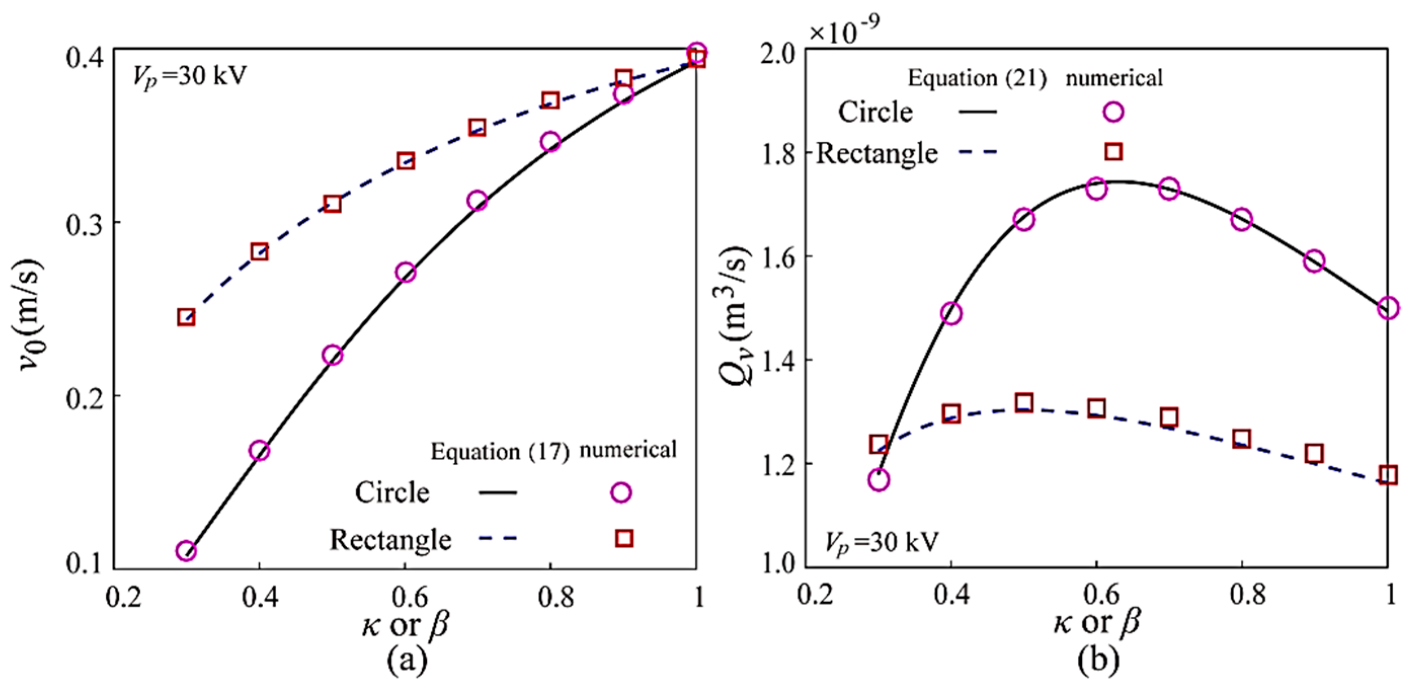
On the basis of the numerical simulations and the theoretical models, Equations (17) and (21), Figure 2 gives the comparisons between the theoretical and numerical results of EOF velocity in the parent microchannel and EOF flowrate both for the Y-shaped circular microchannels and Y-shaped rectangular microchannels with H = 60 μm. It can be found that the numerical and theoretical data are in good agreement with each other, which means the present numerical models and methods are feasible.

3. Results and Discussion

3.1. Effects of Applied Voltage on the Thermal Performances

On the basis of the numerical simulation, Figure 3 gives the effect of different applied voltage on the average convective heat transfer coefficient of EOF in the Y-shaped MCHS with different geometries and configurations. It can be found from Figure 3 that, for each Y-shaped MCHS, the average convective heat transfer coefficient of EOF shows an increasing trend with the increasing applied voltage, which is related to the linearly increasing EOF flowrate with the increasing applied voltage, as shown by both the theoretical and numerical results in Figure 4. This is because the increasing applied voltage generates increasing electric field strength within the microchannel, which enlarges the Helmholtz–Smoluchowski velocity of EOF and the corresponding flowrate, and then leads to the increasing convective heat transfer capability characterized by the average convective heat transfer coefficient, as shown in Figure 3. These results are similar to the previous studies regarding the effects of applied voltage on the flowrate and thermal resistance of the electroosmotically enhanced microchannel heat sinks with parallel channel layout [28].
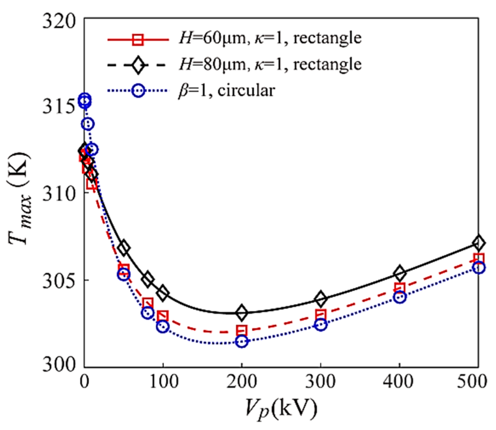
Although both the flowrate and the convective heat transfer coefficient show increasing trends with the increasing applied voltage, the maximum temperature of the MCHS shows a non-monotonous trend with the increasing applied voltage, as shown in Figure 5. When the applied voltage is large enough, the maximum MCHS temperature increases with the increasing applied voltage. This is directly related to the Joule heat effect [26]. On the basis of the definition of Joule heat as λE2, Joule heat increases quadratically with the increasing applied voltage. When the voltage is large enough, the increasing Joule heat will exceed the heat dissipation capability of EOF, resulting in the increase of the maximum MCHS temperature.

3.2. Effects of Channel Cross-Sectional Dimensions on the Thermal Performances

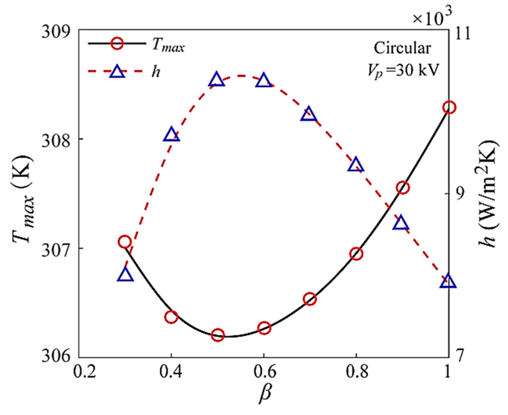
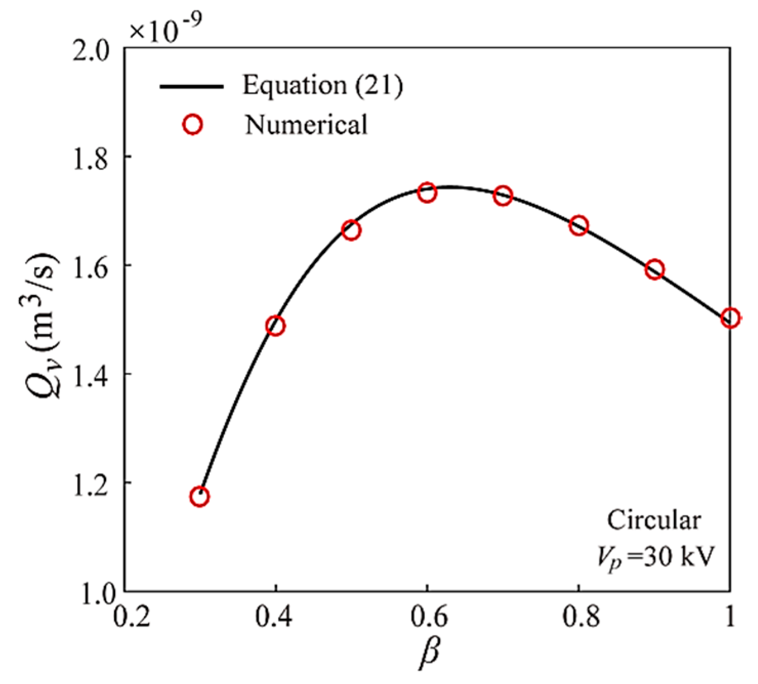
The channel cross-sectional dimension is an important factor to influence the thermal performances of the MCHS; therefore, this present work investigates these effects for the EOF within the Y-shaped MCHS. Figure 6 gives the results of the effects of the daughter-to-parent channel diameter ratio on the maximum MCHS temperature and average convective heat transfer coefficient of the Y-shaped circular MCHS. It can be found that both the maximum MCHS temperature and the average convective heat transfer show non-monotonous trends with the increasing daughter-to-parent channel diameter ratio of the Y-shaped circular microchannels. Specifically, the maximum MCHS temperature shows a decreasing after increasing trend, however, the average convective heat transfer coefficient shows an opposite trend from decrease to increase. This means that the thermal performance displays a manner of first strengthening and then weakening. To further analyze the reasons for these results, Figure 7 gives the effect of the daughter-to-parent channel diameter ratio on the flowrate of EOF. It can be found that the EOF flowrate within the Y-shaped circular microchannels shows a transition from increasing to decreasing with the daughter-to-parent channel diameter ratio, which can be used to explain the trends of maximum MCHS temperature and average convective heat transfer. For the non-monotonous trend of flowrate with the daughter-to-parent diameter ratio, it has actually been well-recognized in both the living and nonliving treelike transport systems to obtain the maximum transport efficiency, which is known as Murray’s law. The results of EOF flowrate shown in Figure 7 show the EOF within the treelike branching microchannel displaying similarity to Murray’s law, which has been reported in our recent studies [10,41].
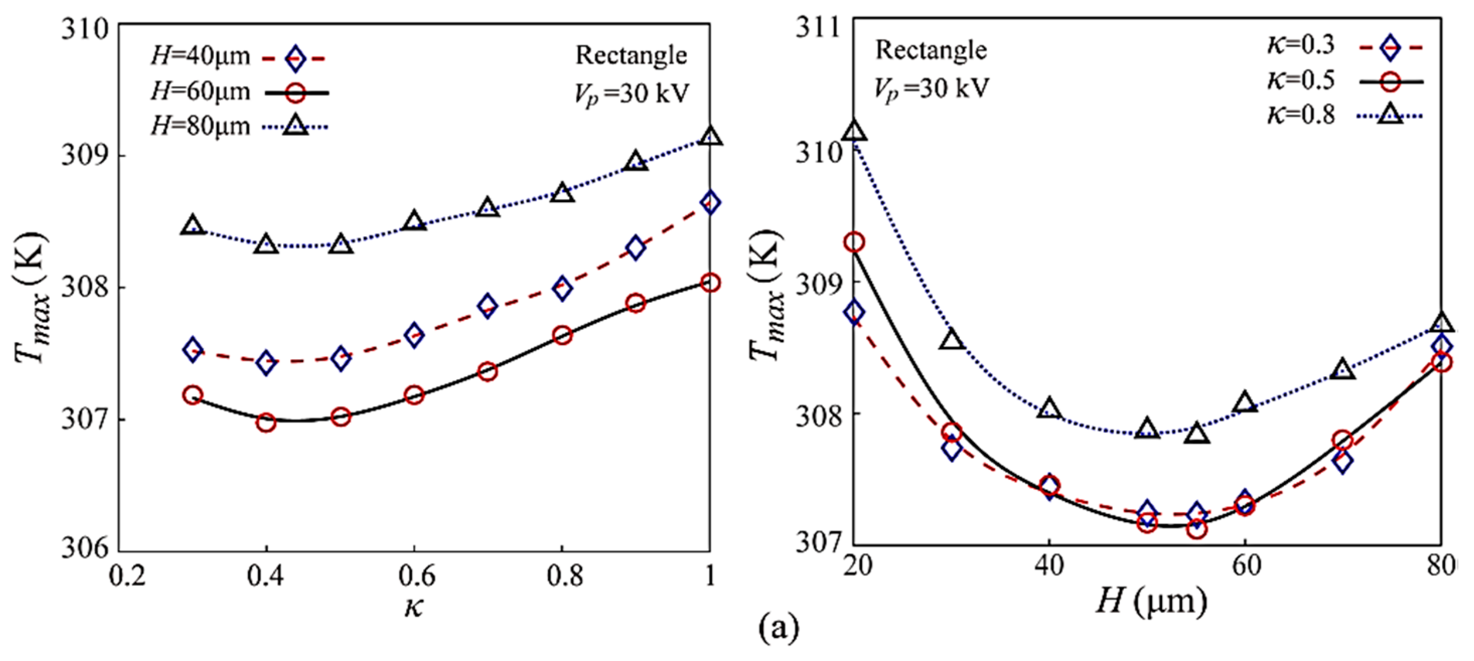
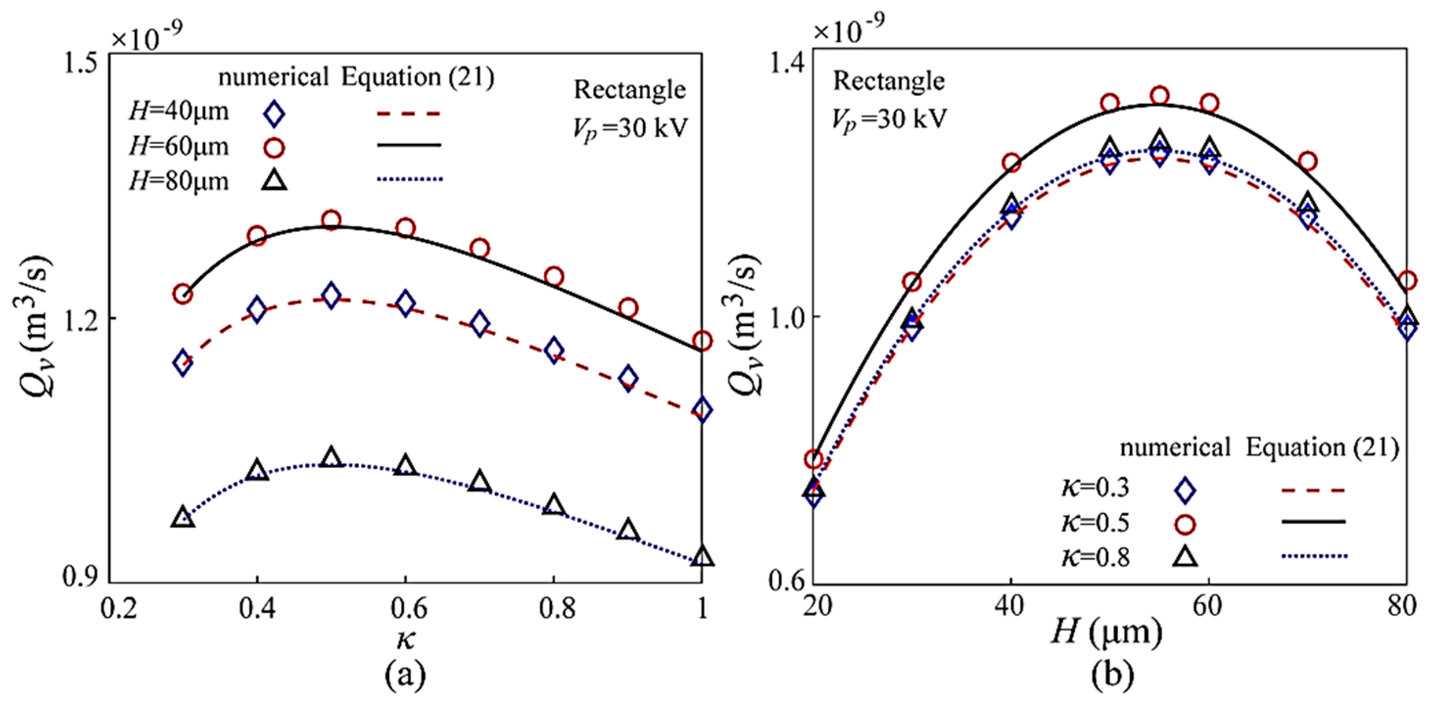
Similarly, Figure 8 gives the effects of the daughter-to-parent channel width ratio and channel height on the maximum MCHS temperature and the average convective heat transfer coefficient of the Y-shaped rectangular MCHS with different geometries and configurations. Similar results with the Y-shaped circular MCHS are obtained for the Y-shaped rectangular MCHS. Both the maximum MCHS temperature and average convective heat transfer coefficient are sensitive to the cross-sectional dimensions of the Y-shaped rectangular microchannel. The maximum MCHS temperature shows a decreasing to increasing trend with the increasing daughter-to-parent channel width ratio of the Y-shaped rectangular microchannel having a given uniform channel height, and with the increasing channel height of the Y-shaped rectangular microchannels having a given daughter-to-parent channel width ratio. However, the average convective heat transfer coefficient shows an opposite trend with the maximum MCHS temperature. Further, Figure 9 gives the effects of the daughter-to-parent channel width ratio and channel height on the EOF flowrate in the Y-shaped rectangular microchannel, which is found to display increasing to decreasing trends. This can be used to explain the effects of the daughter-to-parent channel width ratio and channel height on the maximum MCHS temperature and average convective heat transfer coefficient.
In addition, it should be noted that the trend of flowrate and the trends of thermal performances are not exactly consistent, thus it can be found that the optimal cross-sectional dimensions, where the flowrate and thermal performances are largest, are not exactly the same. Further, although simplified theoretical models have been established to predict the optimal channel cross-sectional dimensions to achieve the maximum EOF flowrate within a Y-shaped microchannel under a given applied voltage [10,41], a simplified method to predict the optimal channel cross-sectional dimensions to achieve the maximum convective heat transfer efficiency is not established because of the complexity of the convective heat transfer, which is not only related to the flowrate, but also depends on other factors like Joule heat, aspect ratio of the rectangular channel, thermal boundary condition, and Reynolds number, which can inevitably affect the thermal performances [27,42,43]. Nevertheless, the present work found that flowrate influences the thermal performances in a positive manner, and both the flowrate and thermal performances of EOF in a Y-shaped MCHS show strengthening to weakening trends with the cross-sectional dimensions both for the circular MCHS and the rectangular MCHS. This provides the inspiration that the flow and thermal performances of the Y-shaped MCHS can be enhanced by optimization of the design of the cross-sectional dimensions.

4. Conclusions

This paper numerically studied the thermal performances including maximum MCHS temperature and average convective heat transfer coefficient of EOF in a Y-shaped MCHS with two channel cross-sectional shapes of circle and rectangle, and investigated the effects of microchannel cross-sectional dimensions of the Y-shaped microchannel on the maximum MCHS temperature and average convective heat transfer coefficient under the constraint of constant total microchannel surface area. The findings in this paper showed that the EOF flowrate displayed an increasing to decreasing trend with the increasing daughter-to-parent channel diameter ratio of the Y-shaped circular microchannel and the increasing daughter-to-parent channel width ratio and increasing channel height of the Y-shaped rectangular microchannel. This further resulted in the average convective heat transfer coefficient first increasing and then decreasing with the increasing daughter-to-parent channel diameter ratio of the Y-shaped circular microchannel and the increasing daughter-to-parent channel width ratio and increasing microchannel height of the Y-shaped rectangular microchannel; however, the maximum MCHS temperature shows an opposite trend to that of the convective heat transfer coefficient. This means the cross-sectional dimensions of a Y-shaped MCHS could be optimized to obtain the maximum EOF heat and mass transport efficiencies, which still need further study.

Author Contributions

Conceptualization, D.J.; data curation, J.S.; formal analysis, D.J.; funding acquisition, D.J.; investigation, J.S.; methodology, D.J.; supervision, D.J.; visualization, J.S.; writing—review and editing, D.J. and J.S. All authors have read and agreed to the published version of the manuscript.

Funding

This research was funded by National Natural Science Foundation of China (Grant No. 51505292).

Conflicts of Interest

The authors declare that they have no conflict of interests for this paper.

References

  1. Tuckerman, D.B.; Pease, R.F.W. High-performance heat sinking for VLSI. IEEE Electron Device Lett. 1981, 2, 126–129. [Google Scholar] [CrossRef]
  2. Gunnasegaran, P.; Mohammed, H.A.; Shuaib, N.H.; Saidur, R. The effect of geometrical parameters on heat transfer characteristics of microchannels heat sink with different shapes. Int. Commun. Heat Mass Transf. 2010, 37, 1078–1086. [Google Scholar] [CrossRef]
  3. Mohammed, H.A.; Gunnasegaran, P.; Shuaib, N.H. Influence of channel shape on the thermal and hydraulic performance of microchannel heat sink. Int. Commun. Heat Mass Transf. 2011, 38, 474–480. [Google Scholar] [CrossRef]
  4. Alfaryjat, A.A.; Mohammed, H.A.; Adam, N.M.; Ariffin, M.K.A.; Najafabadi, M.I. Influence of geometrical parameters of hexagonal, circular, and rhombus microchannel heat sinks on the thermohydraulic characteristics. Int. Commun. Heat Mass Transf. 2014, 52, 121–131. [Google Scholar] [CrossRef]
  5. Liu, Z.G.; Guan, N.; Zhang, C.W.; Jiang, G.L. The flow resistance and heat transfer characteristics of micro pin-fins with different cross-sectional shapes. Nanoscale Microscale Thermophys. 2015, 19, 221–243. [Google Scholar] [CrossRef]
  6. Mohammadi, A.; Koşar, A. Review on heat and fluid flow in micro pin fin heat sinks under single-phase and two-phase flow conditions. Nanoscale Microscale Thermophys. 2018, 22, 153–197. [Google Scholar] [CrossRef]
  7. Chen, Y.P.; Cheng, P. Heat transfer and pressure drop in fractal treelike microchannel nets. Int. J. Heat Mass Transf. 2002, 45, 2643–2648. [Google Scholar] [CrossRef]
  8. Jing, D.; Song, S.; Pan, Y.; Wang, X. Optimal fractal tree-like microchannel networks with slip for laminar-flow-modified Murray’s law. Beilstein J. Nanotechnol. 2018, 9, 482–489. [Google Scholar] [CrossRef]
  9. Jing, D.; Song, J.; Sui, Y. Hydraulic and thermal performances of laminar flow in fractal treelike branching microchannel network with wall velocity slip. Fractals 2020. [Google Scholar] [CrossRef]
  10. Jing, D.; Yi, S. Electroosmotic flow in treelike branching microchannel network. Fractals 2019, 27, 1950095. [Google Scholar] [CrossRef]
  11. Wu, H.Y.; Cheng, P. An experimental study of convective heat transfer in silicon microchannels with different surface conditions. Int. J. Heat Mass Transf. 2003, 46, 2547–2556. [Google Scholar] [CrossRef]
  12. Jing, D.; Song, S.; Pan, Y.; Wang, X. Size dependences of hydraulic resistance and heat transfer of fluid flow in elliptical microchannel heat sinks with boundary slip. Int. J. Heat Mass Transf. 2018, 119, 647–653. [Google Scholar] [CrossRef]
  13. Jing, D.; Pan, Y.; Wang, X.; Heating, J. Viscous dissipation and convective heat transfer of pressure-driven flow in a microchannel with surface charge-dependent slip. Int. J. Heat Mass Transf. 2017, 108, 1305–1313. [Google Scholar] [CrossRef]
  14. Wang, H.; Chen, Z.; Gao, J. Influence of geometric parameters on flow and heat transfer performance of micro-channel heat sinks. Appl. Therm. Sci. 2016, 107, 870–879. [Google Scholar] [CrossRef]
  15. Chen, Y.; Zhang, C.; Shi, M.; Wu, J. Three-dimensional numerical simulation of heat and fluid flow in noncircular microchannel heat sinks. Int. Commun. Heat Mass Transf. 2009, 36, 917–920. [Google Scholar] [CrossRef]
  16. Oh, K.W.; Lee, K.; Ahn, B.; Furlani, E.P. Design of pressure-driven microfluidic networks using electric circuit analogy. Lab Chip 2011, 12, 515–545. [Google Scholar] [CrossRef]
  17. Israelachvili, J. Intermolecular and Surface Forces, 2nd ed.; Academic Press: London, UK, 1991. [Google Scholar]
  18. Hunter, R.J. Foundations of Colloid Science, 2nd ed.; Oxford University Press: New York, NY, USA, 2001. [Google Scholar]
  19. Li, D. Electrokinetics in Microfluidics; Academic Press: Oxford, UK, 2004. [Google Scholar]
  20. Karniadakis, G.E.; Beskok, A. Micro Flows: Fundamentals and Simulation; Springer: Berlin, Germany, 2002. [Google Scholar]
  21. Burgreen, D.; Nakache, F.R. Eletrokinetic flow in ultrafine capillary silts. J. Phys. Chem. 1964, 68, 1084–1091. [Google Scholar] [CrossRef]
  22. Rice, C.L.; Whitehead, R. Electro kinetic flow in a narrow cylindrical capillary. J. Phys. Chem. 1965, 69, 4017–4023. [Google Scholar] [CrossRef]
  23. Keh, H.J.; Liu, Y.C. Electroosmotic flow in a circular capillary with a surface charge layer. J. Colloid Interface Surf. 1995, 172, 222–229. [Google Scholar] [CrossRef]
  24. Herr, A.; Molho, J.; Santiago, J.; Mungal, M.; Kenny, T.; Garguilo, M. Electroosmotic capillary flow with nonuniform zeta potential. Anal. Chem. 2000, 72, 1053–1057. [Google Scholar] [CrossRef]
  25. Xuan, X.; Li, D. Electroosmotic flow in microchannels with arbitrary geometry and arbitrary distribution of wall charge. J. Colloid Interface Surf. 2005, 289, 291–303. [Google Scholar] [CrossRef] [PubMed]
  26. Horiuchi, K.; Dutta, P. Joule heating effects in electroosmotically driven microchannel flows. Int. J. Heat Mass Transf. 2004, 47, 3085–3095. [Google Scholar] [CrossRef]
  27. Shamloo, A.; Merdasi, A.; Vatankhah, P. Numerical simulation of heat transfer in mixed electroosmotic pressure-driven flow in straight microchannels. J. Therm. Sci. Eng. Appl. 2016, 8, 021011. [Google Scholar] [CrossRef]
  28. Husain, A.; Kim, K.-Y. Electroosmotically enhanced microchannel heat sinks. J. Mech. Sci. Technol. 2009, 23, 814–822. [Google Scholar] [CrossRef]
  29. Maynes, D.; Webb, B.W. Fully developed electro-osmotic heat transfer in microchannels. Int. J. Heat Mass Transf. 2003, 46, 1359–1369. [Google Scholar] [CrossRef]
  30. Mandelbrot, B.B. The Fractal Geometry of Nature; Freeman: New York, NY, USA, 1982. [Google Scholar]
  31. Murray, C.D. The physiological principle of minimum work—I: The vascular system and the cost of blood volume. Proc. Natl. Acad. Sci. USA 1926, 12, 207–214. [Google Scholar] [CrossRef] [Green Version]
  32. Xu, P.; Yu, B. The scaling laws of transport properties for fractal-like tree networks. J. Appl. Phys. 2006, 100, 104906. [Google Scholar] [CrossRef] [Green Version]
  33. Xu, P.; Sasmito, A.P.; Yu, B.; Mujumdar, A.S. Transport phenomena and properties in treelike networks. Appl. Mech. Rev. 2016, 68, 040802. [Google Scholar] [CrossRef]
  34. Jing, D.; Song, S.; He, L. Reexamination of Murray’s law for tree-like rectangular microchannel network with constant channel height. Int. J. Heat Mass Transf. 2019, 128, 1344–1350. [Google Scholar] [CrossRef]
  35. Jing, D.; Song, J. Comparison on the hydraulic and thermal performances of two tree-like channel networks with different size constraints. Int. J. Heat Mass Transf. 2019, 130, 1070–1074. [Google Scholar] [CrossRef]
  36. Patankar, N.A.; Hu, H.H. Numerical simulation of electroosmotic flow. Anal. Chem. 1998, 70, 1870–1881. [Google Scholar] [CrossRef] [PubMed]
  37. Ebrahimi, S.; Hasanzadeh-Barforoushi, A.; Nejat, A.; Kowsary, F. Numerical study of mixing and heat transfer in mixed electroosmotic/pressure driven flow through T-shaped microchannels. Int. J. Heat Mass Transf. 2014, 75, 565–580. [Google Scholar] [CrossRef]
  38. Wang, G.; Qian, N.; Ding, G. Heat transfer enhancement in microchannel heat sink with bidirectional rib. Int. J. Heat Mass Transf. 2019, 136, 597–609. [Google Scholar] [CrossRef]
  39. Liu, H.; Qi, D.; Shao, X.; Wang, W. An experimental and numerical investigation of heat transfer enhancement in annular microchannel heat sinks. Int. J. Therm. Sci. 2019, 142, 106–120. [Google Scholar] [CrossRef]
  40. Jing, D.; He, L. Numerical studies on the hydraulic and thermal performances of microchannels with different cross-sectional shapes. Int. J. Heat Mass Transf. 2019, 143, 118604. [Google Scholar] [CrossRef]
  41. Jing, D.; Zhan, X. Cross-sectional dimension dependence of electroosmotic flow in fractal treelike rectangular microchannel network. Micromachines 2020, 11, 266. [Google Scholar] [CrossRef] [PubMed] [Green Version]
  42. Morini, G.L.; Lorenzini, M.; Salvigni, S.; Spiga, M. Thermal performance of silicon micro heat-sinks with electrokinetically-driven flows. Int. J. Therm. Sci. 2006, 45, 955–961. [Google Scholar] [CrossRef]
  43. Shah, R.K.; London, A.L. Laminar Flow Forced Convection in Ducts; Academics Press: New York, NY, USA, 1978. [Google Scholar]
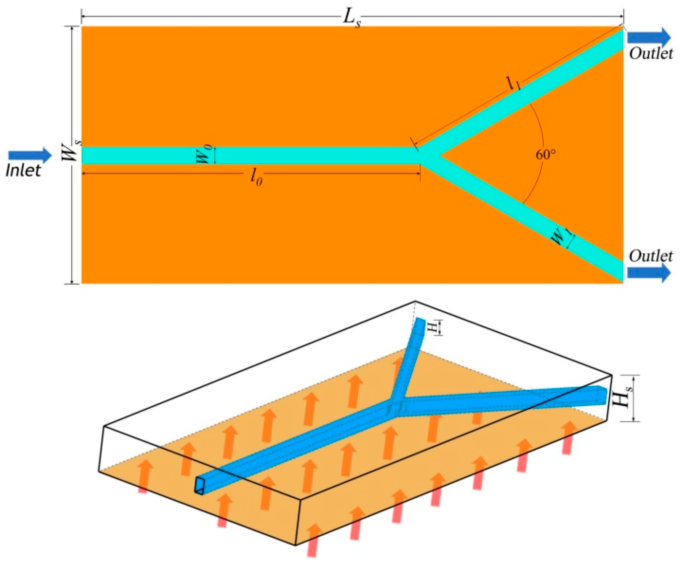
Figure 1. A schematic figure of the Y-shaped rectangular microchannel heat sink (MCHS).
Coatings 10 00380 g001
Figure 2. Validations of electroosmotic flow (EOF) velocity in the parent microchannel (a) and EOF flowrate (b).
Coatings 10 00380 g002
Figure 3. Effect of applied voltage on the average convective heat transfer coefficient of EOF in the Y-shaped microchannels with different geometries and configurations.
Coatings 10 00380 g003
Figure 4. Effect of applied voltage on the flowrate of EOF in the Y-shaped microchannels with different geometries and configurations.
Coatings 10 00380 g004
Figure 5. Effect of applied voltage on the maximum temperature of the Y-shaped microchannel heat sink with different geometries and configurations.
Coatings 10 00380 g005
Figure 6. Effect of daughter-to-parent channel diameter ratio on the maximum temperature and average convective heat transfer coefficient of the Y-shaped circular MCHS.
Coatings 10 00380 g006
Figure 7. Effect of daughter-to-parent channel diameter ratio on the flowrate of EOF in the Y-shaped circular microchannels.
Coatings 10 00380 g007
Figure 8. Effect of daughter-to-parent channel width ratio and channel height on the maximum temperature (a) and average convective heat transfer coefficient (b) of the Y-shaped rectangular microchannel heat sink.
Coatings 10 00380 g008aCoatings 10 00380 g008b
Figure 9. Effect of daughter-to-parent channel width ratio (a) and channel height (b) on the flowrate of EOF in the Y-shaped rectangular microchannels.
Coatings 10 00380 g009
Table 1. Cross-sectional dimensions of the Y-shaped circular microchannels.
Adjusted Diameter Ratio β = d1/d0 of the Daughter Channel and Parent Channel
β10.90.80.70.60.50.40.3
d0 (μm)70.2274.59579.46585.02591.498.8107.475117.775
d1 (μm)70.2267.135563.57259.517554.8449.442.9935.3325
Table 2. Cross-sectional dimensions of the Y-shaped rectangular microchannels with adjusted widths ratio.
Adjusted Widths Ratio κ = W1/W0 of the Daughter Channel and Parent Channel
κH (μm)W0 (μm)W1 (μm)H (μm)W0 (μm)W1 (μm)H (μm)W0 (μm)W1 (μm)
14070.4470.446050.3550.358030.21430.214
0.974.77567.297553.4548.10532.07528.8675
0.879.67563.3456.95545.56434.1827.344
0.785.25359.677160.94542.661536.57625.6032
0.691.6654.99665.53639.321639.33423.6004
0.599.09649.54870.13535.067542.5421.27
0.4107.80843.123277.1230.8646.30618.5224
0.3118.16335.448984.58125.374350.815.24
Table 3. Cross-sectional dimensions of the Y-shaped rectangular microchannels with adjusted uniform channel height.
Adjusted Rectangular Channel Height H of the Parent Channel and Daughter Channel
H (μm)κW0 (μm)W1 (μm)κW0 (μm)W1 (μm)κW0 (μm)W1 (μm)
200.3151.43845.43140.5127.2563.6250.8102.3481.872
30134.93740.4811113.18356.591591.01472.8112
40118.16335.448999.09649.54879.67563.34
50101.42630.427884.98742.568.32354.6584
6093.00527.901577.92538.962562.6450.112
7084.57825.373470.13535.067556.95545.564
8067.70420.311256.7128.35545.57436.4592
Table 4. Thermophysical properties of silicon and deionized water.
MaterialsDensity
(kg/m3)
Thermal Conductivity
(W/(m × K))
Specific Heat
(J/(kg × K))
Viscosity
(Pa × s)
Electrical Conductivity
(S/m)
Permittivity
(F/m)
Si2329130700
Water9960.641821.0 × 10−35.5 × 10−670.8
Table 5. Example of grid independence test.
Test Number iMesh Numbervin [m/s](vini+1vini)/vinivout [m/s](vouti+1vouti)/
vouti
Tmax [K](Tmaxi+1−Tmaxi)
/Tmaxi
12.05 × 1040.3939310.18262307.1497
24.37 × 1040.3937091.55 × 10−30.18122−7.7 × 10−3307.89482.43 × 10−3
31.07 × 1050.3939990.74 × 10−30.18059−3.5 × 10−3308.74342.76 × 10−3
43.02 × 1050.393844−0.39 × 10−30.180760.94 × 10−3309.08231.1 × 10−3