Abstract
To improve the performances of UV-curable coatings, the effects of nano-silica slurry, aluminum and UV-curing time on the glossiness and infrared emissivity of UV-curable coatings were investigated by orthogonal experiments. The results showed that UV-curing time is a key factor affecting the performance of the coating. When the UV-curing time was increased from 30 to 360 s, the glossiness of the UV-curable coating slowly decreased from 11.1% to 9.0%. The L’ value decreased from 78.6 to 75.0. The infrared emissivity of the coating with UV-curing time of 180 s was 0.106, which was the lowest. The coating hardness with different curing time was 6H. The coating roughness was high when the UV-curing time was 30–120 s. When the UV-curing time was greater than 300 s, the coating adhesion was 0 and the coating had the best impact resistance of 500 N/cm. The overall performance of the aluminum/UV-curable coating was optimal when the UV-curing time was 180 s. This research is able to promote the industrial development of UV-curable, infrared, low-emissivity coatings.
1. Introduction
With the rapid development of detective technology, infrared emissivity has become an important indicator [1], widely used in the military [2]. Infrared low-emissivity materials have become an important research topic [3], and the corresponding coating on the surface of such equipment has become a convenient and efficient choice [4], which can prevent the equipment from buckling, deformation, and being detected [5]. An infrared low-emissivity coating plays important roles in both civil and military fields; for instance, camouflaging military equipment or vehicles from infrared detection. However, the existing infrared low-emissivity coatings mainly use conventional polyurethane and epoxy resins as curing film-forming resins, and the curing time required is long, which is not suitable for applications [6]. Due to the high glossiness of aluminum powder, the glossiness of infrared low-emissivity coatings after adding aluminum powder is usually high, which is not conducive to compatibility with visible light. Low glossiness is required for infrared and visible light-compatible coatings. As a new infrared low-emissivity resin, UV-curable coating has the advantages of high curing rate [7], but has the disadvantages of low adhesion and high glossiness [8], which limits its application in infrared low-emissivity materials and is not conducive to infrared light and visible light compatibility [9]. The widely used UV coating system in the industry is unsaturated urethane acrylate [10], and the UV-curable light wavelength is the irradiation wavelength of a medium pressure mercury lamp (310–1000 nm) [11].
Liang et al. [12] prepared four low-infrared-emissivity pigmented coatings using polyurethane as a binder, aluminum as a filler, and nanopigment as a paint. The results showed that the infrared emissivity increases slightly, and the surface glossiness is rapidly reduced by the influence of the nanopigment. Li et al. [13] studied the effects of N2 flow on multilayer AlCrN/Cr/AlCrN tandem coatings, and mainly observed changes in coating structure, precipitation rate, and infrared performance. The results showed that the thicknesses of the tandem coating are inversely related to the N2 flow. The deposited multilayer coating exhibited an emissivity value between 0.0748 and 0.1193, which was positively correlated with the N2 flow. Di Carolo et al. [14] studied a method for measuring different emissivity materials from low temperature to high temperature in aviation. The research showed that the dual color technique has good applicability. The main concern of these studies is the low-emissivity of coatings. However, the coating should not only have low-emissivity, but also good corrosion resistance and compatibility with visible light. At present, the relevant reports are relatively few.
At present, the well-performing, low-cost aluminum powder was used as a metal filler to prepare infrared low-emissivity coating [15]. The nano-silica can reduce the glossiness of the coating and has the unique advantages of nanomaterials [16]. In the previous study, it was found that 20.0%–40.0% aluminum powder is beneficial to reduce infrared emissivity. However, the additive content should not be too high, as it leads to an increase in the infrared emissivity of the coating [17]. In this study, the formulation composition and curing process parameters were optimized by designing the orthogonal experimental scheme, and the effect of nano-silica slurry on aluminum/UV-curable low infrared emissivity coating was explored; we were trying to decrease the infrared emissivity of UV-curable coating, and achieve low glossiness/matte. Considering the compatibility of low infrared emissivity and visible light, the coatings with low infrared emissivity, low glossiness, low brightness, high mechanical properties, and high anti-corrosion performance were obtained, which laid the foundations for the industrial application of UV-curable, infrared, low-emissivity coatings.
2. Materials and Methods
2.1. Experimental Materials
Technical aluminum sheet (100 × 50 × 1 mm3) was supplied by Shanghai Zhanchang Aluminum Industry Co., Ltd., Shanghai, China. UV-curable varnish (the viscosity is 0.025 Pa·s at room temperature) was provided by Pesstorp (Shanghai) Specialty Chemicals Co., Ltd., Shanghai, China. UV-curable varnish was composed of polyurethane acrylate (the concentration was 45.0%), tripropylene glycol diacrylate (the concentration was 20.0%), trimethylolpropane acrylate (the concentration was 30.0%), benzophenone (the concentration was 3.0%), and triethanolamine (the concentration was 2.0%). The solid concentration of the UV-curable varnish was about 99.5%. Al powder 4017 (as filler, Mw: 26.98 g/mol, CAS number: 7429-90-5, diameter: 10 μm, thickness: 220 nm, solid concentration: 65%; 65.0% Al powder mixed with 35.0% oleic acid) was supplied by Zhangqiu Metal Pigment Co., Ltd., Zhangqiu, China. Nano-silica slurry (particle size: 150 nm, solid concentration: 15.0%) was supplied by Suzhou Zhongke Nanotech Coating Co., Ltd., Suzhou, China. Nano-silica was added into the solvents—propylene glycol methyl ether acetate, compound binary acid, butyl acetate, etc.—and grinded with hyperdispersant, rheology agent, and thixotropic agent. KH560 silane coupling agent was provided by Nanjing Aocheng Chemical Co., Ltd., Nanjing, China. FUMAX 650 UV curing instrument (curing wavelength 310–1000 nm) was supplied by Kunshan Ounisite Electronic Technology Co., Ltd., Kunshan, China. The experimental materials mentioned above did not require special treatment.
2.2. Preparation of Coatings
Firstly, the technical aluminum sheet was polished with sandpaper; then degreased; and finally, dried in an oven. The UV-curing time, Al powder, and nano-silica slurry concentration were important factors affecting the performance of Al/UV-curable, infrared, low-emissivity coating. Therefore, the effects of three factors on the performances of the coatings were investigated by orthogonal experiments, and the performances of the coatings were further optimized. Orthogonal experimental design is a multi-factor and multi-level research method. Some representative points were selected from the test. This method is scientific, fast, economical, and can reduce the workload [18]. The concentration of Al powder was 20.0%–40.0%; the concentration of nano-silica slurry was 2.0%–10.0%; and the UV-curing time was 120–360 s. The three-factor and two-level orthogonal experimental variables of the design are shown in Table 1. The formulations are shown in Table 2 (samples 1#–4#). For sample 1#, 20.0 g of Al powder and 2.0 g nano-silica slurry were added to 76.0 g UV-curable coating and mixed evenly; then, 2.0 g KH560 was added, mixed, and stirred evenly. The mixture was coated on pre-treated flat technical aluminum sheet using an SZQ tetrahedral fabricator (Tianjin Jinghai Science and Technology Testing Machinery Factory, Tianjin, China), making the coating flat and smooth. Then, the coated aluminum sheet was irradiated in FUMAX 650 UV curing instrument for 120 s. The samples 2#–14# were also prepared according to Table 2. The coated substrate was cured for 120 s for samples 1# and 4#, for 360 s for samples 2# and 3#, and for 180 s for samples 5#–8# respectively. UV-curing times for samples 9#–14# were 30, 60, 120, 180, 240, and 300 s, respectively. The photoinitiator (benzophenone) in the UV-curable varnish, after absorbing the high-intensity ultraviolet light produced in FUMAX 650 UV curing instrument, produces active free radicals or cations, thus initiating polymerization, cross-linking, and grafting reactions, and making the coating change from liquid to solid in a certain period of time. The thickness of the dry UV-curable coating was about 60 μm.

Table 1.
Orthogonal experiment table.
Table 2.
Compositions of coatings.
2.3. Testing and Characterization
A quanta 200 environmental scanning electron microscopy (SEM), FEI Company, Hillsboro, OR, USA, was used to analyze the microstructures of the coatings. A VERTEX 80V infrared spectrometer (Germany Bruker Co., Ltd., Karlsruhe, Germany) was used to analyze the compositions of the coatings. The hardness of each coating was tested by 6H–6B pencils [19]. A QCJ impactor was used to measure the strength of each coating. In the impact test, a 1.0 kg ball fell freely from different heights (the maximum height is 50.0 cm). The damage on each coating was observed after the ball fell on the surface of the coating. Impact strength was the maximum height at which the ball could fall without damaging the coating. The glossiness of each coating was measured by the BGD512-60° gloss meter produced by Suzhou Essen Instrument Equipment Co., Ltd., Suzhou, China. The adhesion of a coating was tested by QFZ-II coating adhesion tester. The impactor and adhesion tester were produced by Tianjin Jingkelian Material Testing Machine Co., Ltd., Tianjin, China. The infrared emissivity of the coating range of 8–14 μm was tested on the infrared dual-wave infrared radiometer (Shanghai Institute of Technological Physics of the Chinese Academy of Sciences, Shanghai, China). The coating roughness was tested using the JB-4C roughness meter (Shanghai Taeming Optical Instrument, Shanghai, China) [20]. The HP-2136 chromatometer (Zhuhai Tianchuang Instrument Co., Ltd., Zhuhai, China) was used to directly measure the chromatic values of coatings. On the electrochemical workstation CHI750C (Shanghai Chenhua Instrument Co., Ltd., Shanghai, China), the samples were immersed in a 3.5% NaCl solution to test the corrosion resistance of the coating at room temperature. The reference electrode in the electrochemical test system was a saturated calomel electrode, and the counter electrode was a platinum plate. When the open-circuit potential was stable, the scanning potential was open-circuit potential ±0.3 V, the scanning interval was 0.6 V, and the scanning speed was 10 mV/s. According to ASTM B117 procedure [21], a salt spray test of corrosion performance was carried out in a salt spray cabinet. The samples were exposed to a salt spray produced by a 5.0% NaCl solution with a pH of 6.5–7.2 for 30 days. The temperature in the chamber was kept at 35 °C. A single blade cutter was used to make cross scratches on the coating surface. The test sample sheet was inspected periodically by visual inspection [22]. After the sample plate was taken out of the salt spray cabinet, the surface damage on the test plate was observed, and the glossiness and color difference of the coating were tested. All the experiments were repeated four times, and the error was less than 5.0%.
3. Results and Discussion
3.1. Analysis of Orthogonal Analysis of Aluminum/UV-Curable Coating
Coating glossiness and infrared emissivity are important parameters of coating performance, so in the orthogonal test, the effects on glossiness and infrared emissivity were examined respectively, and then the effects on other properties were further investigated by independent experiments. The samples in Table 3 are the samples 1#–4# in Table 2. For sample 1#, the concentrations of Al powder, nano silica slurry, KH560, and UV-curable varnish were 20.0%, 2.0%, 2.0%, and 76.0%, respectively. By judging the experimental range (R), the greater the range, the more significant the influence of this factor on the experimental results, and the greater the influence on the glossiness and infrared emissivity results [23]. By calculating the difference between Rs from Table 3 and Table 4, it can be found that the effects of UV-curing time on glossiness and infrared emissivity are more significant. This may be due to the influence of the fillers on the coating being not been fully reflected at 120 s of UV curing, and it takes a longer time for the coating to react completely [24]. UV curing uses ultraviolet light to irradiate the coating, which produces radiation polymerization, radiation crosslinking, and grafting reactions, and rapidly transforms low molecular substances into high molecular products. At the beginning of UV curing, the energy of UV irradiation is mainly used for the cross-linking reaction of resin, and the coating becomes hard and compact. However, with the extension of curing time, UV light may cause the degradation of the polymer chain in the coating and damage to Al powder, so the UV-curing time should not be too long.
Table 3.
Orthogonal experiment of glossiness.
Table 4.
Orthogonal experiment of emissivity.
From the results of the above orthogonal experiment, sample 3# had a lower glossiness and infrared emissivity. The amount of nano-silica slurry to be added in sample 4# is large, and the price of raw materials is expensive, which is not conducive to industrial production. It can be seen from the results of orthogonal experiments that the UV-curing time has the greatest impact on the coating performance. Based on this results and consideration of low-emissivity performance, further independent experiments of the UV-curing time were necessary. Therefore, the aluminum powder concentration was set as 40.0%, nano-silica slurry was set as 2.0%, silane coupling agent was set as 2.0%, and UV-curing time was 60, 120, 180, 240, 300, or 360 s, respectively. The effects of UV-curing time on the glossiness, infrared emissivity, and color difference of coating were investigated.
3.2. The Effect of UV-Curing Time on Glossiness
The results of the effect of UV-curing time on coating glossiness are shown in Figure 1. The glossiness of the UV-curable coating showed a slow downward trend with UV-curing time increasing. When the UV-curing time increased from 30 to 360 s, the glossiness of the UV-curable coating slowly decreased from 11.1% to 9.0%, a decrease of only 2.1%. This is because with increasing the time, the nano-silica slurry begins to act slowly, reducing the coating’s glossiness [25]. During UV curing, the solvent in the nano-silica slurry will volatilize slowly, which will weaken the visible light reflection of the particles and reduce the glossiness [26]. The glossiness of the UV-curable coating is within the range of matte-level glossiness, and the gap is not large. For low-infrared-emissivity technology, the lower the glossiness of the coating, the better the effect. From this, it can be concluded that the UV-curing time has little effect on the glossiness of the UV-curable coating.
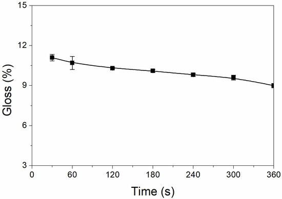
Figure 1.
Effect of UV-curing time on the glossiness of the coating (samples 3# and 9#–14# in Table 2).
3.3. The Influence of UV-Curing Time on the Infrared Emissivity
The influence of UV-curing time on the infrared emissivity of the coating is shown in Figure 2. The infrared emissivity of the UV-curable coating showed a U-shaped trend. When the UV-curing time was extended from 30 to 180 s, the infrared emissivity of the UV-curable coating dropped from 0.267 to 0.106. However, as the UV-curing time continued to be extended from 180 to 360 s, the emissivity of the UV-curable coating increased from 0.106 to 0.221. This is because the addition of nano-silica slurry accelerates the curing of the coating during the period of 30 to 180 s of UV curing. However, after UV curing for 180 s, the coating cured more completely, and the UV light may have partially damaged the surface of the aluminum powder in the coating, which made aluminum powder distribution unevenly (Figure 3), so the infrared emissivity of the coating began to rise. Figure 3 is SEMs of the coating after different UV-curing times; there are relatively large gaps between the particles in Figure 3B,F, and there is a relatively uniform arrangement of the particles in Figure 3D. Figure 4 shows the FT-IR spectra of the coating after the different UV-curing times. The N–H stretching vibration is 3355 cm−1; 2942 cm−1 and 1444 cm−1 are –CH-characteristic absorption; 1721 cm−1 is –C=O– characteristic absorption; 1159 cm−1 is C–O stretching vibration; and 1256 cm−1 is the N–C–O stretching vibration, which indicates that there is no significant change in the coating’s absorption peak during curing. It can be seen from Figure 2 that the UV-curing time has a great influence on the infrared emissivity of the UV-curable coating. Considering the low infrared emissivity performance, the UV-curing time required to achieve the best curing degree of the coating is 180 s.
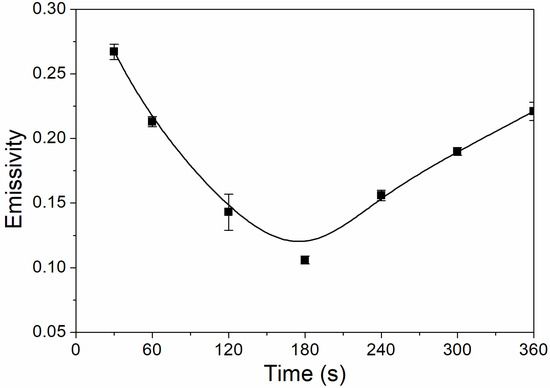
Figure 2.
The influence of UV-curing time on the infrared emissivity of the coating (samples 3# and 9#–14# in Table 2).
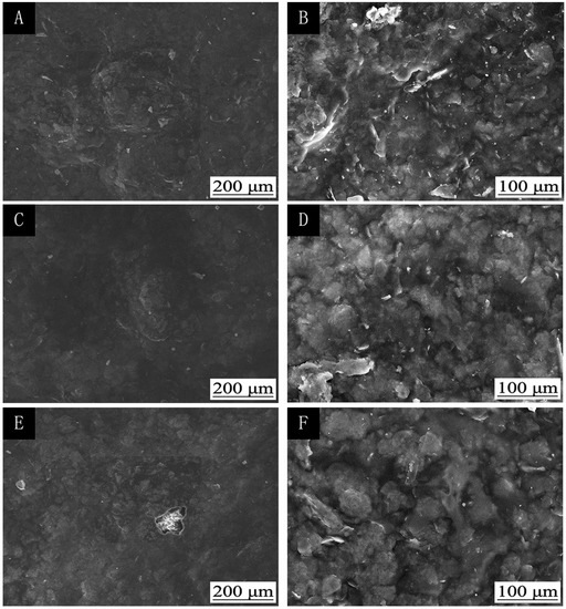
Figure 3.
The influence of UV-curing time on the SEMs of coatings: low (A) and high (B) magnification of 30 s; low (C) and high (D) magnification of 180 s; low (E) and high (F) magnification of 360 s (samples 3#, 9#, and 12# in Table 2).
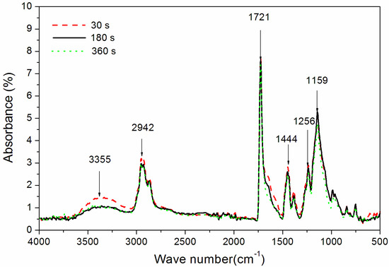
Figure 4.
The influence of UV-curing time on the FT-IR spectra of coatings (samples 3#, 9#, and 12# in Table 2).
3.4. The Influence of UV-Curing Time on the Color Difference
L, a*, and b* respectively represent the brightness, red green value, and yellow blue value. A positive value of L indicates that the surface color of the measured object is light, while a negative value indicates dark. In Table 5, L is the value of technical aluminum sheet, and L’ is the value of the coated technical aluminum sheet. The lower the L’ value of the coating, the darker the surface and the better the compatibility with visible light. ΔL, Δa*, and Δb* are respectively expressed as the change values of black and white, red green, and yellow blue. ΔL = L’ − L, Δa* = a*’ − a*, Δb* = b*’ − b*. The color difference ΔE is calculated according to Equation (1) [27]:
ΔE = [(ΔL)2 + (Δa*)2 + (Δb*)2]1/2
Table 5.
Color difference table (samples 3#, 9#–14# in Table 2).
The influences of the UV-curing time on the color differences and the L’ values of the coating are shown in Table 5. The L’ values of UV-curable coatings decreased with the increase of UV-curing time, but did not change much. The value of a*’ was less in the UV curing for 30–60 s, and there was no significant change in UV curing for 120–180 or 240–300 s. The UV-curable 300–360 s was smaller to the previous few minutes. The b*’ value did not change significantly within 120 s of UV curing, but fluctuated significantly after UV curing for 180 s. When the UV-curing time increased from 30 s to 360 s, the L’ value of UV-curable coatings decreased from 78.6 to 75.0. This is because as time goes on, the coating solidifies slowly, the color becomes dark, the brightness decreases, and the L’ value decreases accordingly [28]. At the same time, the color difference ΔE decreased gradually; this is because with the extension of UV-curing time, the UV-curable coating components react completely [29].
3.5. The Influences of UV-Curing Time on Hardness and Roughness
When the UV-curing time was 30–360 s, the coating had a very high hardness, greater than 6H. This is because the hardnesses of the UV coating and silica itself are very high, and the addition of the nano-silica slurry can greatly improve the hardness of the coating. It can be seen from Figure 5 that the coating’s roughness was relatively high when UV curing was performed for 30–120 s, and was relatively low when UV-curing time was 180–360 s. This is because the coating is not fully cured before UV curing for 180 s; the coating particles are uneven, and the roughness is very high. After UV curing for 180 s, the nano-silica slurry may have a catalytic effect, reduce the activation energy of the reaction, and improve the reaction rate [30]; and the coating cured completely, which reduced the roughness [31].
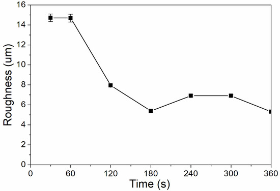
Figure 5.
The influence of UV-curing time on the roughness of the coating (samples 3# and 9#–14# in Table 2).
3.6. The Influences of UV-Curing Time on Adhesion and Impact Strength
As shown in Figure 6, the coating adhesion was 1 level at the UV-curing time of 30–240 s, and the coating adhesion was higher at 300–360 s, which was 0 level. This is because after 180 s, the coating solidifies completely, the micro diameter of particles is relatively small, and the force between particles is relatively large, which improves the adhesion of coating to aluminum sheet [32]. As Figure 7 showed, the impact resistance of the coating had generally increased from 300 N/cm to 500 N/cm as the UV-curing time was extended. This is because as the curing time increases, the coating cures more thoroughly.
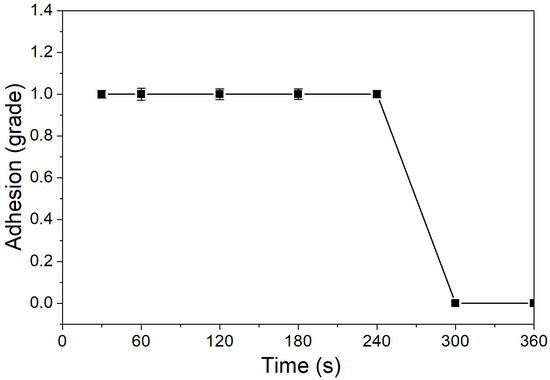
Figure 6.
The influence of UV-curing time on adhesion of coating (samples 3# and 9#–14# in Table 2).
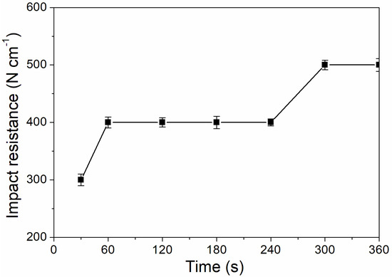
Figure 7.
The influence of UV-curing time on the impact resistance of the coating (samples 3# and 9#–14# in Table 2).
3.7. The Effect of UV-Curing Time on Corrosion Resistance
From the above results, when the curing time was 180 s, the performance of the coating was better. Therefore, the sample with a curing time of 180 s was tested for its corrosion resistance. Figure 8 and Figure 9 are electrochemical polarization curves of coatings at different UV-curing times. The data in the figure were calculated by the software, and the values are shown in Table 6. The equilibrium potential is about −0.745 V; the left side of −0.745 V is the anode Tafel curve; the right side of −0.745 V is the cathode Tafel curve. Lower corrosion current and higher polarization resistance represent a slower corrosion rate and weaker corrosion trend respectively [33]. The higher the polarization resistance of Rp, the lower the corrosion current density of Icorr and the better the corrosion resistance. As can be seen from Table 6, when the UV-curing time was increased from 30 s to 180 s, the resistance of the coating increased and the corrosion current density decreased, so the corrosion resistance of the coating increased slightly.
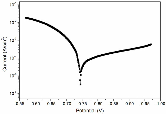
Figure 8.
Electrochemistry diagram of a coating—UV-curing time 30 s (sample 9# in Table 2).
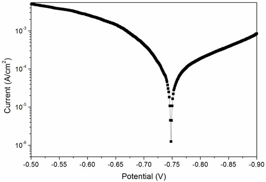
Figure 9.
Electrochemistry diagram of a coating—UV-curing time 180 s (sample 12# in Table 2).
Table 6.
The effect of UV-curing time on salt spray test corrosion resistance (samples 9# and 12# in Table 2).
No blistering or shedding was observed after the salt spray test. As shown in Table 7, when the UV-curing time was 180 s, there was no obvious color change of the coating, and the color difference changed slightly, which was 1.0. In addition, the loss of glossiness was small when the UV-curing time was 180 s, indicating that the coating has better corrosion resistance, which is consistent with the electrochemical test results (Figure 9).
Table 7.
Changes to glossiness and color difference after salt spray tests (samples 9# and 12# in Table 2).
3.8. The Effect of Al Powder Concentration on the Property
On this basis, the effect of Al powder concentration on the coating’s performance was tested for, as shown in Table 8. As the Al powder concentration increased, the emissivity of the coating decreased, and the glossiness decreased. The high glossiness of the coating without the nano-silica slurry was not conducive to visible light compatibility. When the Al powder concentration was 40.0%, the nano-silica slurry concentration was 2.0%, and UV-curing time was 180 s; the coating had low infrared emissivity and glossiness. The comparison results with other infrared low-emissivity coatings [18,33,34,35,36] are shown in Table 9. The glossiness of Al/UV-curable coating modified by nano-silica slurry is lower than that of PU-based coating, which is similar to that of epoxy based coating and Al/waterborne acrylic coating. The adhesion and impact resistance of Al/UV-curable coatings modified by nano-silica slurry are relatively good, which are level 1 and 400 N cm−1, respectively.
Table 8.
Effect of Al powder concentration on glossiness and infrared emissivity (samples 5#–8# and 12# in Table 2).
Table 9.
Comparison of infrared emissivity coatings.
Based on the above analysis, it can be concluded that UV-curable varnish can be used to prepare low infrared emissivity coatings with good properties. The UV-curable varnish was characterized. The infrared spectrum is shown in Figure 10. An N–H stretching vibration of 3355 cm−1, a carbonyl-characteristic absorption of 1721 cm−1, a –CH-characteristic absorption of 2942 cm−1, and a C–O stretching vibration of 1159 cm−1 can be observed.

Figure 10.
Infrared spectrum of UV-curable varnish.
4. Conclusions
These experiments were done to study the three factors of Al powder concentration, nano-silica slurry concentration, and UV-curing time. It is concluded that compared with Al powder concentration and nano-silica slurry concentration, UV-curing time is the key factor for the preparation of infrared low-emissivity, UV-curable coatings. The effects of UV-curing time on low infrared emissivity, low-matte coating, and low-glossiness values were explored by changing the UV-curing time. It was found that when the UV-curing time was 180 s, the UV-curable coating had lower glossiness, the lowest infrared emissivity, a lower L’ value, and less variation in color difference and glossiness, which reduced the likelihood of being detected by infrared wave detection equipment. The SEM and FI-IR results were not significant, indicating that the coating composition and microstructure did not change much. At the same time, when the UV-curing time was 180 s, the UV-curable coating had a higher hardness, adhesion level of 1, low roughness, good impact resistance, and good corrosion resistance. When the Al powder concentration was 40.0%, the nano-silica slurry concentration was 2.0%, and UV-curing time was 180 s, and the coating had low infrared emissivity and glossiness. Compared with the coatings in other literature, the experimental coating has low glossiness, low-emissivity, and good mechanical properties. Therefore, when the UV-curing time is 180 s and the Al powder concentration is 40.0%, the overall performance of the UV-curing coating is better. Infrared and visible compatible coatings require low glossiness. The application of low glossiness and low-emissivity coatings can reduce the risk of being detected by infrared light and visible light. The preparation parameters of UV-curable low-emissivity and low glossiness coating were discussed, which provides a new prospect for the industrial application of UV-curable, infrared, low-emissivity coatings.
Author Contributions
Conceptualization, methodology, validation, resources, data curation, writing—original draft preparation, and supervision, X.Y.; formal analysis, Y.C. and X.Q.; investigation and writing—review and editing, Y.C. All authors have read and agreed to the published version of the manuscript.
Funding
This research was funded by the Youth Science and Technology Innovation Fund of Nanjing Forestry University, Grant No. CX2016018.
Conflicts of Interest
The authors declare no conflict of interest.
References
- Vishnevetsky, I.; Rotenberg, E.; Kribus, A.; Yakir, D. Method for accurate measurement of infrared emissivity for opaque low-reflectance materials. Appl. Opt. 2019, 58, 4599–4609. [Google Scholar] [CrossRef] [PubMed]
- Luo, H.; Zhang, X.J.; Huang, S.X.; Shan, D.Y.; Deng, L.W.; He, L.H.; He, J.; Xu, Y.C.; Chen, H.; Liao, C.W. Infrared emissivity and microwave transmission behavior of flaky aluminum functionalized pyramidal-frustum shaped periodic structure. Infrared Phys. Tech. 2019, 99, 123–128. [Google Scholar] [CrossRef]
- Guo, M.Z.; Cao, B.; Fan, W.J.; Ren, H.Z.; Cui, Y.K.; Du, Y.M.; Liu, Q.H. Scattering effect contributions to the directional canopy emissivity and brightness temperature based on CE-P and CBT-P models. IEEE Geosci. Remote. Sens. Lett. 2018, 16, 957–961. [Google Scholar] [CrossRef]
- Coll, C.; Niclos, R.; Puchades, J.; Garcia-Santos, V.; Galve, J.M.; Perez-Planells, L.; Valor, E.; Theocharous, E. Laboratory calibration and field measurement of land surface temperature and emissivity using thermal infrared multiband radiometers. Int. J appl. Earth. Obs. 2019, 78, 227–239. [Google Scholar] [CrossRef]
- Xu, W.; Fang, X.Y.; Han, J.T.; Wu, Z.H.; Zhang, J.L. Effect of coating thickness on sound absorption property of four wood species commonly used for piano soundboards. Wood Fiber. Science 2020, 52, 28–43. [Google Scholar] [CrossRef]
- Qin, Y.S.; Zhang, M.J.; Guan, Y.; Huang, X.G. Laser absorption and infrared stealth properties of Al/ATO composites. Ceram. Int. 2019, 45, 14312–14315. [Google Scholar] [CrossRef]
- Wu, Y.; Wu, X.; Yang, F.; Ye, J. Preparation and characterization of waterborne UV lacquer product modified by zinc oxide with flower shape. Polymers 2020, 12, 668. [Google Scholar] [CrossRef]
- Wang, L.; Xu, G.Y.; Liu, C.Y.; Hou, H.L.; Tan, S.J. Surface-modified CeO2 coating with excellent thermal shock resistance performance and low infrared emissivity at high-temperature. Surf. Coat. Tech. 2019, 357, 559–566. [Google Scholar] [CrossRef]
- Liu, Y.F.; Xie, J.L.; Luo, M.; Peng, B.; Xu, C.; Deng, L.J. The synthesis and optical properties of Al/MnO2 composite pigments by ball-milling for low infrared emissivity and low lightness. Prog. Org. Coat. 2017, 108, 30–35. [Google Scholar] [CrossRef]
- Yuan, L.; Weng, X.L.; Xie, J.L.; Deng, L.J. Effects of shape, size and solid content of Al pigments on the low-infrared emissivity coating. Mater. Res. Innov. 2015, 19 (Suppl. 1), S325–S330. [Google Scholar] [CrossRef]
- He, L.H.; Zhao, Y.; Xing, L.Y.; Liu, P.G.; Zhang, Y.W.; Wang, Z.Y. Low infrared emissivity coating based on graphene surface-modified flaky aluminum. Materials 2018, 11, 1502. [Google Scholar] [CrossRef] [PubMed]
- Liang, J.; Li, W.; Xu, G.Y.; Meng, X.; Liu, K.; Tan, S.J. Preparation and characterization of the colored coating with low infrared emissivity based on nanometer pigment. Prog. Org. Coat. 2018, 115, 74–78. [Google Scholar] [CrossRef]
- Li, Q.Y.; Cheng, X.D.; Gong, D.Q.; Ye, W.P. Effect of N2 flow rate on structural and infrared properties of multi-layer AlCrN/Cr/AlCrN coatings deposited by cathodic arc ion plating for low emissivity applications. Thin Solid Film. 2019, 675, 74–85. [Google Scholar] [CrossRef]
- Di Carolo, F.; Savino, L.; Palumbo, D.; Del Vecchio, A.; Galietti, U.; De Cesare, M. Standard thermography vs free emissivity dual color novel CIRA physics technique in the near-mid IR ranges: Studies for different emissivity class materials from low to high temperatures typical of aerospace re-entry. Int. J. Therm. Sci. 2020, 147, 106123. [Google Scholar] [CrossRef]
- Guinneton, F.; Sauques, L.; Valmalette, J.C.; Cros, F.; Gavarri, J.R. Role of surface defects and microstructure in infrared optical properties of thermochromic VO2 materials. J. Phys. Chem. Solids 2005, 66, 63–73. [Google Scholar] [CrossRef]
- Qi, D.; Wang, X.; Chen, F.; Cheng, Y.Z.; Gong, R.Z. Metal-based graphical SiO2/Ag/ZnS/Ag hetero-structure for visible-infrared compatible camouflage. Materials 2018, 11, 1594. [Google Scholar] [CrossRef] [PubMed]
- Liu, Y.F.; Xie, J.L.; Luo, M.; Jian, S.; Peng, B.; Deng, L.J. Preparation and angle-dependent optical properties of brown Al/MnO2 composite pigments in visible and infrared region. Nanoscale Res. Lett. 2017, 12, 266. [Google Scholar] [CrossRef]
- Yan, X.X.; Wang, L.; Qian, X.Y. Preparation and characterization of low infrared emissive aluminum/waterborne acrylic coatings. Coatings 2020, 10, 35. [Google Scholar] [CrossRef]
- GB/T 6739-2006 Paints and Varnishes—Determination of Film Hardness by Pencil Test; Standardization Administration of the People’s Republic of China: Beijing, China, 1998; pp. 1–3. (In Chinese)
- Xiong, X.Q.; Yuan, Y.Y.; Niu, Y.T.; Zhang, L.T. Research on the effects of roughness on the tactile properties of rice straw particleboard surface. Sci. Adv. Mater. 2020, 12, 795–801. [Google Scholar] [CrossRef]
- ASTM B117-16 Standard Practice for Operating Salt Spray (Fog) Apparatus; ASTM International: West Conshohocken, PA, USA, 2016. [CrossRef]
- Simpson, C.H.; Ray, C.J.; Skerry, B.S. Accelerated corrosion testing of industrial maintenance paints using a cyclic corrosion weatherin method. J. Prot. Coat. Linings 1991, 8, 28–36. [Google Scholar]
- Yan, X.X.; Qian, X.Y.; Lu, R.; Miyakoshi, T. Comparison and optimization of reactive dyes and coating performance on Fraxinus mandshurica veneer. Polymers 2018, 10, 1302. [Google Scholar] [CrossRef] [PubMed]
- Labukas, J.P.; Escarsega, J.A.; Crawford, D.M. Accelerated drying of water-dispersible polyurethane blends. J. Coat. Technol. Res. 2014, 11, 217–229. [Google Scholar] [CrossRef]
- Li, N.; Bao, M.Z.; Rao, F.; Shu, Y.; Huang, C.J.; Huang, Z.H.; Chen, Y.H.; Bao, Y.J.; Guo, R.C.; Xiu, C.M. Improvement of surface photostability of bamboo scrimber by application of organic UV absorber coatings. J. Wood. Sci. 2019, 65, 7. [Google Scholar] [CrossRef]
- Yan, X.X.; Qian, X.Y.; Lu, R.; Miyakoshi, T. Synergistic effect of addition of fillers on properties of interior waterborne UV-curing wood coatings. Coatings 2018, 8, 9. [Google Scholar] [CrossRef]
- Malm, V.; Straat, M.; Walkenstrom, P. Effects of surface structure and substrate color on color differences in textile coatings containing effect pigments. Text. Res. J. 2014, 84, 125–139. [Google Scholar] [CrossRef]
- Zhou, X.; Mao, J.; Qiao, Z. Electroless plating of copper layer on surfaces of urea-formaldehyde microcapsule particles containing paraffin for low infrared emissivity. Particuology 2016, 24, 159–163. [Google Scholar] [CrossRef]
- Ye, X.Y.; Zheng, C.; Xiao, X.Q.; Cai, S.G. Synthesis, characterization and infrared emissivity study of SiO2/Ag/TiO2 “sandwich” core-shell composites. Mater. Lett. 2015, 141, 191–193. [Google Scholar] [CrossRef]
- Banerjee, S.; Santra, S. Remarkable catalytic activity of silica nanoparticle in the bis-Michael addition of active methylene compounds to conjugated alkenes. Tetrahedron Lett. 2009, 50, 2037–2040. [Google Scholar] [CrossRef]
- Guo, L.; Jing, L.Z.; Liu, Y.; Zou, B.J.; Hua, S.C.; Zhang, J.P.; Yu, D.Y.; Wang, S.C.; Wang, S.R.; Wang, L.D.; et al. Enhanced dispersion of graphene in epoxy-acrylic waterborne anticorrosion coating: Bifunctional ligands linking graphene to SiO2. Int. J. Electrochem. Sci. 2018, 13, 11867–11881. [Google Scholar] [CrossRef]
- Liu, N.; Xu, G.Y.; Guo, T.C.; Meng, X.; Tan, S.J. Effect of Co-60 gamma ray irradiation on adhesion of LIE coatings. Surf. Eng. 2017, 33, 820–826. [Google Scholar] [CrossRef]
- Yan, X.X.; Xu, G.Y. Effect of surface modification of Cu with Ag by ball-milling on the corrosion resistance of low infrared emissivity coating. Mater. Sci. Eng. B Adv. 2010, 166, 152–157. [Google Scholar] [CrossRef]
- Yan, X.X.; Xu, G.Y. Influence of silane coupling agent on corrosion-resistant property in low infrared emissivity Cu/polyurethane coating. Prog. Org. Coat. 2012, 73, 232–238. [Google Scholar] [CrossRef]
- Yan, X.X.; Xu, G.Y. Corrosion and mechanical properties of polyurethane/Al composite coatings with low infrared emissivity. J. Alloys Compd. 2010, 491, 649–653. [Google Scholar] [CrossRef]
- Yan, X.X.; Cai, Y.T.; Lu, R.; Miyakoshi, T. Development and characterization of new coating material of blended epoxy-lacquer with aluminum. Int. J. Polym. Sci. 2017, 5017356. [Google Scholar] [CrossRef]


© 2020 by the authors. Licensee MDPI, Basel, Switzerland. This article is an open access article distributed under the terms and conditions of the Creative Commons Attribution (CC BY) license (http://creativecommons.org/licenses/by/4.0/).