1. Introduction
Among the different types of plasmas, atmospheric plasma spraying (APS) is one of the main thermal spray processes that has been widely used for the deposition of ceramic or metallic materials [
1,
2]. APS has been used for different technological applications in coating deposition, such as in high performance thermal barrier coatings (TBCs) [
3], evaluation of infiltration mechanisms of volcanic ashes in TBCs [
4], alternative energies such as solid oxide fuel cells [
5], among others.
Several torch models have evolved in design to allow optimal interactions of feeding powder with the plasma generated by a non-transferred DC arc plasma system. In most cases, powder feeding is externally injected into the plasma torch at atmospheric pressure. Under these conditions, the plasma jet and in some cases material characteristics can be affected by the contact with oxygen from ambient air, particularly because it may alter chemical compositions of plasma species, cool the thermal plasma flame, and reduce the jet velocity.
Among the methods to overcome the possible negative effects of air entrainment, torch design has incorporated a shroud gas injection system. For instance, the original design of the Metco 9MB plasma torch is based on a plasma cutting system for metals and was modified for coating deposition adding an external powder injection system and changing the internal gas flow to generate swirling in a de Laval nozzle located at the gun´s frontal section. This plasma torch design was patented in the fifties and is known as Gage’s design [
6]. Other shroud systems consist of annular channels mounted on the torch exit that blocks the ambient air into the plasma stream [
7].
It is in general well accepted that the shroud gas system leads to an improvement of the coating characteristics because it stabilizes the plasma conditions. The dynamics of this gas shielding shell in the Metco 9MB plasma jet consists of a swirling effect of the injected gases that is characteristic of each plasma torch geometrical design and is represented by a swirl number [
8]. The swirl number has been previously defined as the ratio of angular to axial momentum in the heated gases, which has been the object of several studies [
8,
9,
10,
11]. For instance, the flow structure of a turbulent thermal plasma jet was studied by Spores et al. to determine the swirl number [
11].
Since the efficiency and quality of ceramic coatings deposited by APS depend on the full understanding of the plasma-particles interaction, experimental and theoretical approaches are needed to describe specific effects of the plasma stream, especially those that cause deviations of the ideal trajectories of in-flight particles.
3D-modeling investigations based on plasma jet k-epsilon equation model including the effect of turbulence dispersion analysis, transverse particle, and carrier-gas injection on the particle trajectories have been reported elsewhere. In these 2D or 3D axisymmetric coordinate system models, the critical process parameters such as temperature, velocity, and turbulent parameter distributions within the plasma jet are predicted from the numerical solution of continuity, momentum, species, energy, turbulent kinetic energy and its dissipation rate governing equations [
12,
13].
Additionally, other specific parameters of shroud gas injection such as velocity, swirl number, width, and mass flux have been numerically investigated seeking to define their effects on APS [
14,
15]. For instance, a numerical analysis based on a fluid model assuming a steady local thermodynamic equilibrium plasma was reported for the analysis of air entrainment into a non-transferred torch plasma with shroud gas injection in normal atmospheric pressure conditions. It has been reported that shroud gas injection reduces remarkably air entrainment into the plasma stream without significantly affecting its characteristics except for a slight decrease in temperature and velocity at the plasma jet downstream region [
16].
Some effects of shroud gas injection on material properties of tungsten layers coated by plasma spraying have been reported elsewhere. However, to the author´s best knowledge no specific experimental evidence of the effect of swirling on in-flight particle trajectories has been reported yet.
In this work, the static and dynamic footprints of a 9MB plasma torch were analyzed as a function of stand-off distance seeking evidence of swirling effects in the 3D trajectories of Al2O3 in-flight particles. The swirling effect was validated by a proprietary mathematical model that considers the size of the injection holes for the shroud gases and their geometry.
3. Results and Discussion
The analysis of both dynamic and static footprints aims to evidence complex phenomena associated with plasma swirl effects on in-flight particle trajectories and thus deposition footprints.
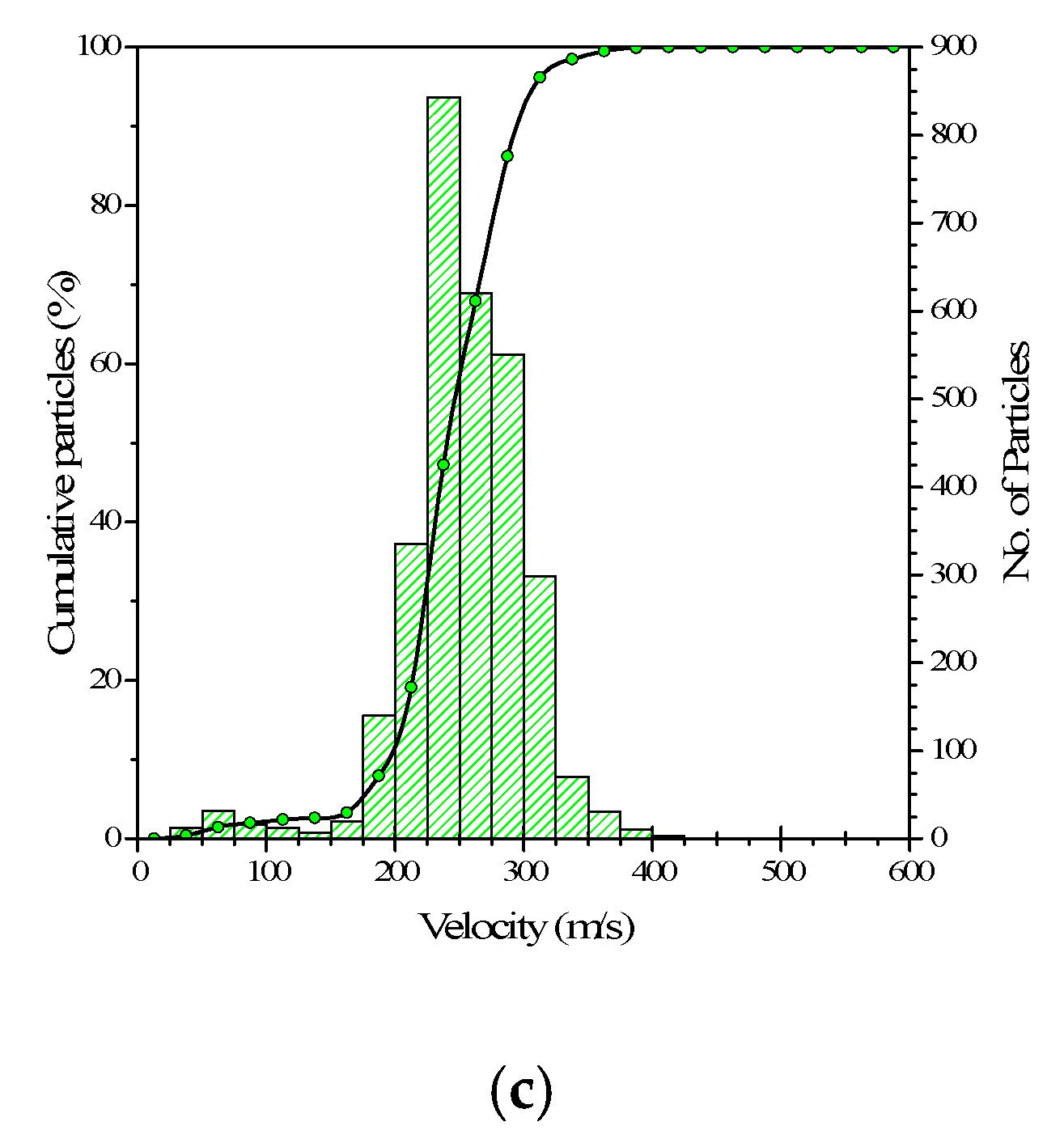
Figure 1 shows results of size distribution of alumina powder (Metco 105NS) as well as representative size distribution data, temperature and velocities of in-flight particles recorded with the DPV-Evolution at a SOD = 90 mm. The alumina powder showed an average particle size of 22.83 μm measured by light scattering. The size distribution of the powder and in-flight particles as measured by the DPV-Evolution system can be described by
d10 = 11 μm,
d50 = 22.8 μm and
d90 = 37 μm and
d10 = 13 μm,
d50 = 20.4 μm and
d90 = 31 μm, respectively (
Figure 1a). A slight decrease in size, especially of bigger particles can be observed as a result of plasma-particle interactions, that typically leads to droplets formation [
1,
9,
17,
21,
26]. This size distribution was used to feed the theoretical model for the calculation of particle trajectories of specific sizes.
Diagnostics of in-flight particles also allows to determine the temperature and velocities measured with the DPV-Evolution (
Figure 1b,c).
3.1. Static and Dynamic Spray Footprints
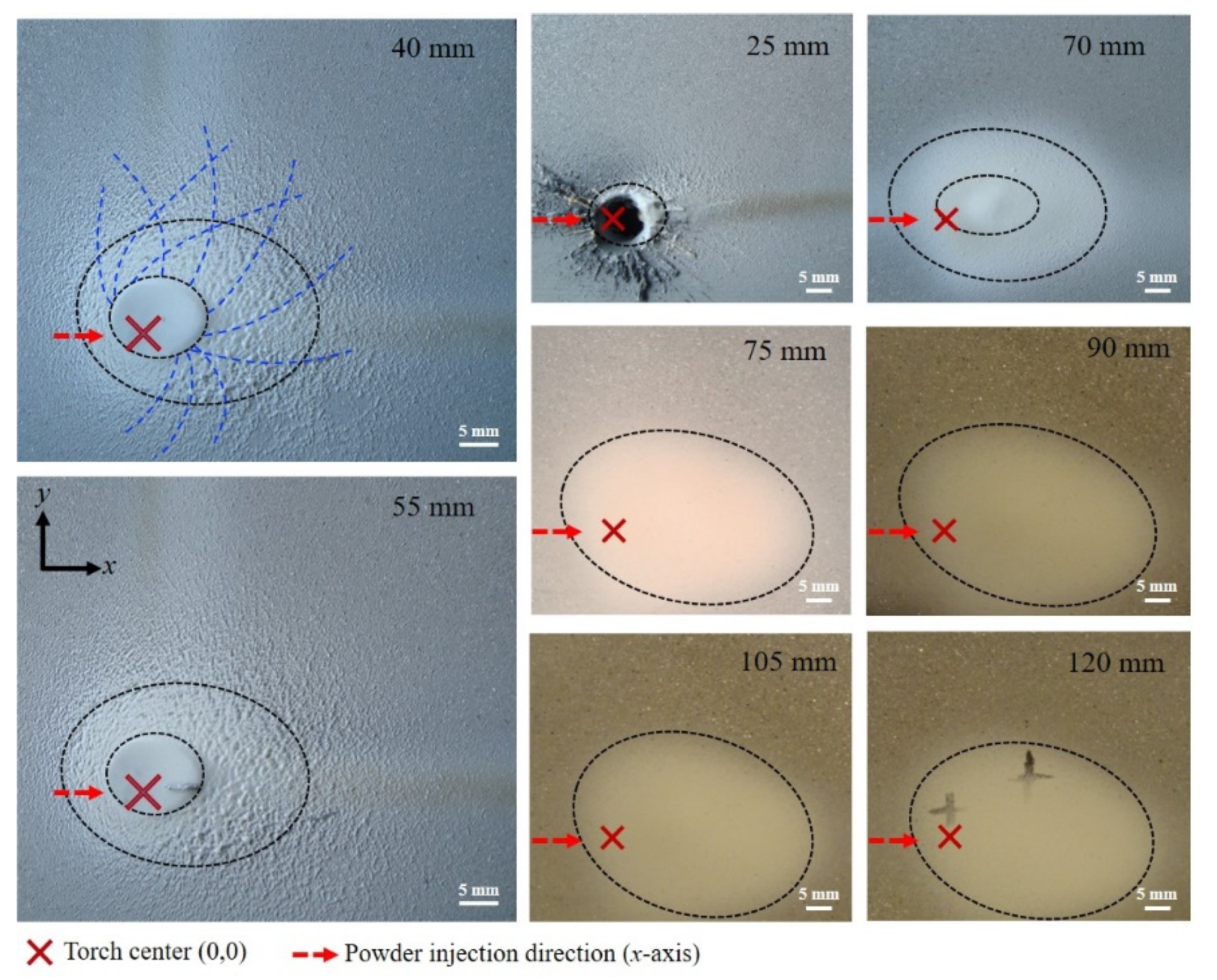
Results of the static footprint of alumina at SOD from 25 to 120 mm deposited on Al6061 alloy substrates are shown in
Figure 2. The red cross in each image represents the center of the plasma stream meanwhile, the black-dashed lines indicate the impacted particles footprint boundaries. The powder injection direction was kept constant and has been indicated in
Figure 2 as a red-dashed arrow. The static footprints have an ellipsoidal shape and present a rightward displacement, respect to the center of the jet, regardless of the stand-off distance.
In the case of the sample sprayed at 25 mm, the plasma stream drilled the substrate with the remaining impacted particles on the right side. The dimensions of the ellipses increased as the spray distance varies from 25 to 70 mm and remains almost constant after 75 mm. Moreover, due to the constant powder flow at one single point, the footprint presents a mound inside the ellipse, which is flatted on the top when the SOD is in the range between 40 and 70 mm (see the double dashed ellipse in
Figure 1). This effect is due to the high kinetic energy of the impacted particles and gas stream at high temperatures at short distances that leads to the formation of a pool of molten particles. The calculated temperature of particles at a SOD = 40 mm is 2970 °C. The measured temperatures by DVP-Evolution of in-flight particles at a SOD = 90 mm is 2414 °C (
Figure 1b). On the other hand, the trajectories of particles of different sizes in the plasma jet have been reported in the literature [
12,
21,
27]. It is thus expected that the smallest particles follow the jet main path, are melted and form a pool of molten particles, which immediately solidifies due to the nature of the experiment (1 s) leading to the formation of the flatted mound.
As the SOD increases, this flattening effect is not observed anymore, and the ellipse slightly tilts clockwise. This rotation was measured, and it was about 0 and 9 degrees from the horizontal injection showing a cumulative effect of rotation for samples with the longest SOD. For the longest spray distances the footprint fades and the particles seem to be mainly affected by gravity.
Additional evidence of swirl can be observed on the samples sprayed at 40 and 55 mm, where the impacted particles showed a swirled path at the footprint valley. Some path patterns of these particles are highlighted with blue-dashed lines in the image recorded at SOD = 40 mm.
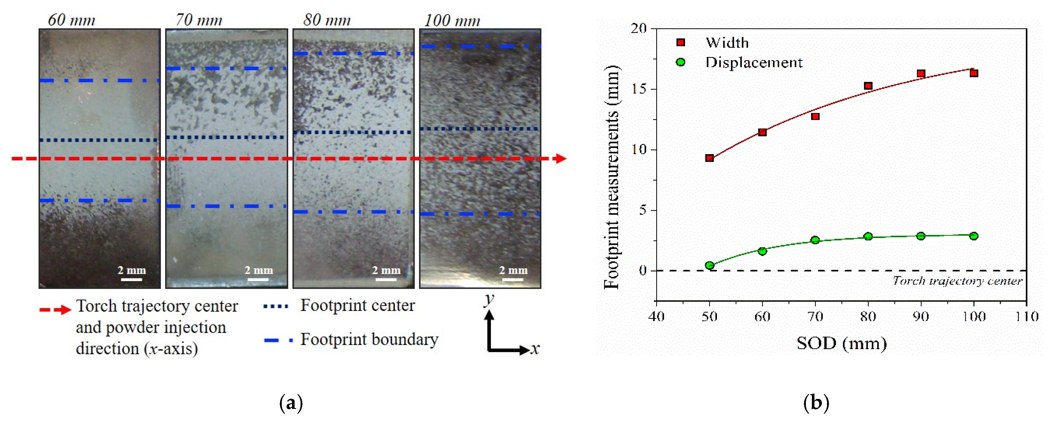
Figure 3 shows the results of the dynamic footprint (spray trace) corresponding to samples sprayed at the centerline of the Al6061 alloy substrates as a function of SOD. The minimum tested SOD was 50 mm to avoid substrate drill effects. As expected, the analysis of the dynamic footprint is only sensitive to
y-displacements.
Figure 3a shows a set of photographs of the dynamic footprints corresponding to samples sprayed from 60 to 100 mm. From these images, the red-dashed line represents the trajectory along the
x-axis (at zero
y). As observed, most of the particles impacted above the torch axis and the correspondent footprint become wider as the distance increases. Results of width and displacement of dynamic footprints are presented in
Figure 3b as a function of SOD. The footprint width varies from approx. 9.3 to 16.3 mm and the displacement range from approx. 0.4 to 2.9 mm as the SOD increases from 50 to 100 mm. Short SOD tends to match with the torch axis (displacement
y = 0 mm).
As mentioned before, a horizontal injection was used to identify between swirl from plasma current and gravity effects on particles impacting the substrate. No influence of gravity on the trajectories of injected in-flight particles was observed at short SOD distances since the combination of powder micrometric size, velocity conditions in the plasma stream, and short spraying distances becomes dominant.
3.2. Theoretical Validation of Swirl
Figure 4 shows part of the argon-hydrogen plasma stream simulated with the previously described CFD code and the 5 to 70 μm in-flight trajectories of 130 particles to create the spray cone. The geometry of the Metco 9MB plasma torch was measured to locate the main nozzle outlet (7.5 mm outer diameter) and the injection point (axial and radial distances of 5 and 9 mm, respectively) for the pneumatic powder injector, the injection tube diameter was also measured diameter (3.0 mm internal diameter). By employing these data, a powder injection velocity of 16.69 ± 2.25 m/s was determined using the theory for a fluid moving within a tubing [
28]. For modeling purposes, the torch swirl number was calculated as
Sn = 0.169 ± 0.058 using the axial momentum of the injected gases, their axial and tangential velocities, the number of gas injection holes, along with their diameters and radial location, following a procedure reported elsewhere [
14]. The torch thermal efficiency was estimated to be 56 ± 6.4% by considering the electrical power supplied to form the arc and the heat removed through the cooling system.
As for the experimental approach the stand-off distance for a plasma stream was set as 120 mm with several cuts to measure the impact of the particles (from 15 to 120 mm). The injection of particles with different sizes was numerically simulated. As expected, at the point of impact a spray mountain is formed, in which (x, y) target coordinates for the static footprint are defined and compared to the experimental values.
The footprint position consistently showed a shift in the "
y-axis" vertical direction that confirms the presence of swirling gases into the plasma stream when powder injection is along the “
x–axis” and the plasma jet is perpendicular and axially moved over the “
z-axis”, as described in
Figure 3. These swirling effects cause a twist in the path of the particles during spray deposition moving or shifting the particles away from the center of the plasma stream, i.e., to locations of lower temperature and velocities. This displacement is mainly due to the swirling effect which induces a change in the powder particles trajectory. Similar results have been reported by Williamson et al. [
10] considering two swirling plasma numbers.
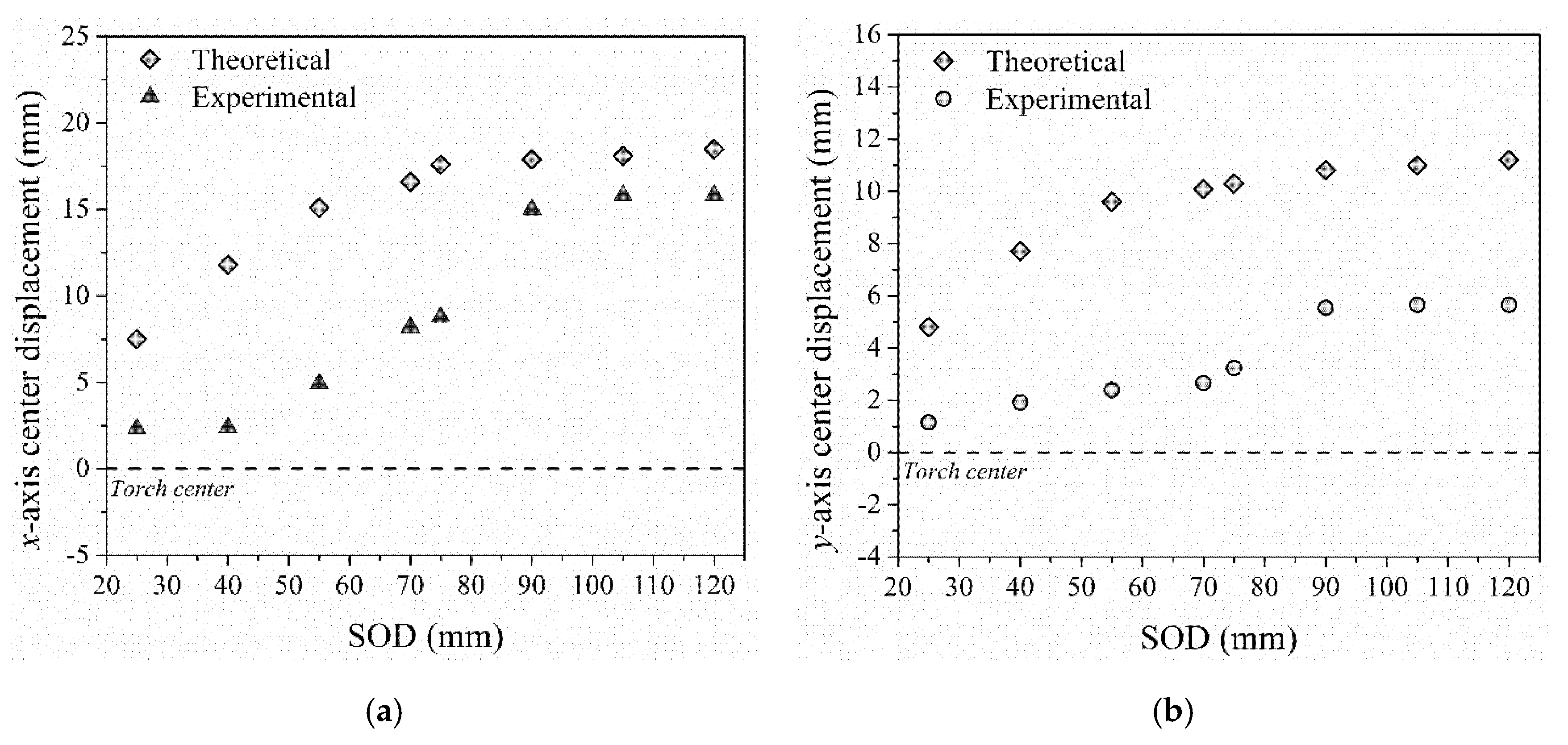
Figure 5 shows a summary of the experimental and simulation results of
x- and
y-displacements of the static footprint respect to the plasma torch center.
As mentioned above, the footprint presents a displacement on both
x- and
y-axis increasing in the range from 2.5 to 15 mm and from ~1 to 5 mm, respectively, as the SOD increases from 25 to 120 mm. A similar behavior is observed for the predicted values, where the calculated
x-axis displacement shows increase from 7.5 to 17.5 mm and the
y-axis increases from 5 to 11 mm. Both displacements show an increase, with respect to the torch center as SOD increases from 25 to 90 mm. However, this behavior is more pronounced for the
x-direction. At further SOD, an almost steady-state or plateau is reached. These results indicate that the swirl component significantly affects the particle trajectory in
x- and
y-directions. However, its effect diminishes at longer SOD being slight gravity effects more dominant. Chyou et al. [
9] and Williamson et al. [
10] have reported mathematical simulation results of a swirling effect on particle trajectory in a plasma stream. It was found that swirling causes (a) clockwise helical trajectories of particles heading downstream with the plasma jet [
9] and (b) a displacement of the spray pattern in directions perpendicular to the plasma stream leading to the formation of a footprint outside the center of the plasma jet [
10]. The current experimental evidence validates these previous modelling results.
These swirling effects of Al
2O
3 sprayed with a Metco-9MB torch are expected to be different other types of spraying systems, e.g., even modifying the powder injection system [
29] or by changing the characteristics of the feeding material such as in suspension or solution plasma spraying [
30,
31]. The reason is not only because of the nature of the feeding material (size distribution, medium, etc.) but also because the overall mechanism of transformation/evolution of suspension or solution droplets in the plasma jet is different to that occurring when conventional powder feeding systems are employed in APS. As a result, the microstructure of SPS and APS coatings is very different. Further work is needed to extend this approach to suspension and solution precursor plasma sprayed coatings in order to include the transformation/evolution mechanisms of suspension or solution droplets in the plasma jet.

 ,
, 