Article

Properties of Graphene-Thermoplastic Polyurethane Flexible Conductive Film

1
Zhongshan Institute, University of Electronic Science and Technology of China, Zhongshan 528402, China
2
School of Material and Energy, University of Electronic Science and Technology of China, Chengdu 610054, China
3
Department of Materials Science and Engineering, Tsinghua University, Beijing 100084, China
*
Author to whom correspondence should be addressed.
Coatings 2020, 10(4), 400; https://doi.org/10.3390/coatings10040400
Submission received: 3 April 2020 / Revised: 11 April 2020 / Accepted: 16 April 2020 / Published: 18 April 2020

Abstract

:
Flexible conductive films were prepared via a convenient blending method with thermoplastic polyurethane (TPU) as matrix and nanocrystalline cellulose (NCC) modified chemically reduced graphene oxide (RGO/NCC) as the conductive fillers. The relationships between the electrical and thermal properties as well as the tensile strength and electrothermal response performance of the composite film and the mass content of reduced graphene oxide (RGO) and the initial TPU concentration were systematically investigated. The experimental results show that the resistivity of the composite film with the mass content of RGO/NCC of 7 wt% and an initial TPU concentration of 20 wt% is the minimum of 8.1 Ω·mm. However, the thermal conductivity of composite film with mass content of RGO/NCC of 5 wt% and the initial TPU concentration of 30 wt% reaches a maximum of 0.3464 W·m−1·K−1, which is an increase of 56% compared with pure TPU. The tensile strength of the composite films with mass contents of RGO of 3 wt% prepared with the initial TPU concentrations of 20 wt% reaches the maximum of 43.2 MPa, which increases by a factor of 1.5 (the tensile strength of the pure TPU is 28.9 MPa). The composite conductive film has a fast electrothermal response. Furthermore, superhydrophobic composite conductive films were prepared by immersing the composite conductive film into fluorinated decyl polyhedral oligomeric silsesquioxane (F-POSS) ethanol solution. The water contact angle of the superhydrophobic composite conductive film reaches 158.19° and the resistivity of the superhydrophobic composite film slightly increases and still has good conductivity.

1. Introduction

In recent years, with the development trend of electronic equipment toward the intelligence, miniaturization, and multi-functions, flexible conductive composites have attracted more attention in scientific research and industry and were widely used in the fields of wearable electronic devices, stretchable antennas, electroluminescent devices, flexible displays, energy devices, and more [1,2,3,4,5]. Flexible conductive composites are often used as electrodes for flexible devices, which functionalizes in building connections between different components of the devices. Until now, the flexible conductive composites are typically fabricated by embedding conductive nanomaterial into or onto a surface of an elastic matrix, plastic, or fabric cotton [6,7,8,9]. Polymer materials, such as epoxy, polyimide, and polyurethane, used as flexible matrices are generally insulating. The conductive nanomaterial commonly used include carbon nanotubes [10], graphene [11], metal nanowires [12], and their composites [13]. The conductive nanomaterial filled in the elastic matrix contact each other to form electrical networks that make the free electrons travel easily and conduct the electricity [14,15,16,17,18,19]. These conductive composite materials are lightweight, resistant to corrosion, and can be easily adapted to meet the needs of a specific application. Therefore, they may replace the metals in some applications [10,11,12,13]. However, the poor interfacial compatibility between conductive nanomaterial with a polymer matrix results in the poor dispersion [20,21].
Among them, graphene, which is a two-dimensional nanomaterial, is receiving growing interest and is widely used in sensors, field-effect transistors, energy, and gas storage, etc. [22,23,24,25,26]. Graphene is considered to be a promising next generation conductive nanomaterial because of its excellent electrical and thermal conductivity and mechanical properties with fracture trains of ca. 25% and a Young’s modulus of ca.1 TPa, and the light weight, which make it highly suitable for flexible electronic devices [14,15,16,17,18,19,20]. Graphene-based conductive composite materials prepared require a certain amount of graphene sheets that are incorporated and homogeneously distributed into polymer matrices [27,28,29,30,31,32,33]. Stankovich et al. reported that a polystyrene-graphene composite formed via complete exfoliation of graphite and molecular-level dispersion of individual chemically-modified graphene sheets within polystyrene exhibited a percolation threshold of approximately a 0.1 volume percentage for room-temperature electrical conductivity, and, at only 1 volume percentage, this composite has a conductivity of approximately 0.1 S·m−1. Viet et al. reported that the polystyrene-chemically converted graphene composite prepared by solution blending is followed by compression molding, which exhibited a percolation threshold as low as 0.19 vol.% and an electrical conductivity as high as 72.18 S·m−1 similar to 2.45 vol.%. Dhakal et al. reported that they prepared conductive composite thin films by dispersing graphene in PANI (polyaniline) [29]. Barjasteh et al. reported that they prepared conductive polyamide-graphene composite fabric via interface engineering [30]. Kim et al. reported, for the first time, self-healable polyurethane (PU) nanocomposites containing modified graphene by the near infrared radiation (IR) absorption of graphene [31]. Huang et al. reported that they prepared thermoplastic polyurethane (TPU) containing a few layers of graphene and their healing performance by microwave radiation [32]. Luan et al. reported that the healing performance of TPU composites are filled with grapheme - carbon nanotubes (CNTs) under microwave radiation [33].
Most of the previous research work related to the polymer composites containing graphene mainly focus on improving the electrical and mechanical properties [22,23,24,25,26,27,28,29,30,31,32,33,34]. To the best of our knowledge, there are few reports that systemically investigate graphene-polymer composites as flexible conductive films. In this paper, flexible conductive films were prepared via a convenient blending method with thermoplastic polyurethane (TPU) as matrices and nanocrystalline cellulose (NCC) modified chemically reduced graphene oxide (RGO/NCC) as the conductive fillers and systematically investigated the electrical and thermal properties of RGO/NCC-TPU flexible conductive film. Furthermore, superhydrophobic composite conductive films were prepared by immersing the composite conductive film into fluorinated decyl polyhedral oligomeric silsesquioxane (F-POSS) ethanol solution and effect of superhydrophobic treatment on the electrical properties of RGO/NCC-TPU conductive film was studied. Compared with the literature reports, in our experiment, graphene sheets obtained by reducing the NCC dispersed graphene oxide (GO) with hydrazine hydrate and washing and concentrating them into a slurry were added into TPU solution and then dispersed by a high-speed shear disperser. NCC is a rod or spherical whisker structure material with a high specific surface area and a large number of hydroxyl groups. The thermal and mechanical properties of PU with NCC can be improved [35]. Both of NCC and GO have good hydrophilicity. When NCC and GO are mixed in an aqueous solution, they not only interact through a hydrogen bond, but also some NCC can be inserted into the graphene sheets structure, so that they can be dispersed well in aqueous solution under ultrasonic conditions. Furthermore, when GO is reduced in the solution, NCC with rich polar oxygen-containing groups can form hydrogen bonds, π-π interactions with the remaining oxygen-containing polar groups on the graphene surface, and non-covalent interactions such as electrostatic force, etc., so that NCC modified chemically RGO with good dispersion can be prepared in an aqueous solution. In addition, RGO/NCC was added into TPU in the form of slurry, which can improve the dispersion of graphene in the TPU solution.

2. Experimental Approach

2.1. Materials

Flaky graphite (≥ 99.9%) was purchased from Jiangsu Xianfeng Nanomaterial Technology Co., Ltd. (Nanjing, China). Sulfuric acid (AR) and hydrochloric acid (AR) were purchased from Guangzhou Chemical Reagent Co., Ltd. (Guangzhou, China). Hydrogen peroxide (AR) and potassium permanganate (AR) were purchased from Guangzhou Panyu District Jianxing Reagent Co., Ltd. (Guangzhou, China). Sodium nitrate (AR) and hydrazine hydrate (≥ 80%) were purchased from Tianjin Baishi Chemical Co., Ltd. (Tianjin, China). Thermopolyurethane (TPU) was from Decron thermoplastic polyurethane (Dongguan) Co., Ltd. (Dongguan, China). Microcrystalline cellulose (≥ 99.8%) and ammonia (25%) were purchased from Tianjin Yongda Chemical Reagent Co., Ltd. (Tianjin, China). All the chemicals were used as received. 1H,1H,2H,2H-Perfluorodecyltriethoxysilane (PDTOS, ≥ 97%) were purchased from Aladdin chemical Co., Ltd., Shanghai, China. octa(vinylsilsesquioxane) (PSS-OVS, ≥ 95%) and 2,2-dimethoxy-phenylacetophenone (DMPA, ≥ 99%) were purchased from Sigma-Aldrich Co., Ltd., Shanghai, China. Methylene chloride (≥ 99.5%) was purchased fromTianjin Baishi Co., Ltd., Tianjin, China. N, N-Dimethylformamide (DMF, ≥ 99.5%) was purchased from Guangzhou Chemical Reagent Co., Ltd., Guangzhou, Guangdong, China. All the chemicals were used as received.

2.2. Preparation of G-TPU Composite Film

2.2.1. Preparation of RGO/NCC Slurry

Graphene oxide (GO) was prepared from flaky graphite using a modified Hummers method [36]. The GO was washed and centrifuged using a water-to-HCl volume ratio of 9:1. The GO mixture was centrifuged again and washed with deionized (DI) water until the pH of the solution was reduced to 6. The GO obtained, therefore, was diluted using DI water to 1 mg·mL−1. Nano-crystalline cellulose (NCC) was prepared by sulfuric acid hydrolysis from microcrystalline cellulose. Additionally, 100 mL of 50% sulfuric acid was added to a three-mouth flask. Then, 6 g of microcrystalline cellulose were added into sulfuric acid solution and dissolved under electric stirring. After microcrystalline cellulose completely dissolved, the reaction solution was heated to 40 °C and stirring continued for 2 h to obtain an NCC suspension. The NCC suspension was transferred into a 5000 mL beaker and added 1000 mL of DI water. The NCC suspension was washed and centrifuged until the pH of the solution was reduced to 2. The NCC suspension obtained was diluted using DI water to 10 mg·mL−1.
A total of 100 mL of GO solution and 100 mL of NCC solution were ultrasonic at 400 W and 40 °C for 1 h, respectively. Then, the GO and NCC mixed solution with the mass ratio of 1:1.5 was prepared and dispersed by ultrasound at 400 W and 40 °C for 1 h to obtain the GO/NCC mixed solution. The GO/NCC mixed solution was added into a three-necked flask. Then hydrazine hydrate (weight ratio of hydrazine hydrate to GO is 8:10) and ammonia water (volume ratio of ammonia to hydrazine hydrate is 5:1) were added into the mixed solution under vigorous stirring and heated at 95 °C for 2 h. Lastly, the product was filtered through a 0.2 μm filter to obtain reduced graphene oxide and NCC (RGO/NCC) slurry. The mass content of RGO/NCC in the slurry was measured using a gravimetric method.

2.2.2. Preparation of RGO/NCC-TPU Composite Film

According to the experimental formula, a certain amount of TPU masterbatch were dissolved in 500 mL of DMF. A formulated amount of RGO/NCC slurry was added into a flask containing DMF solution under vigorous stirring and ultrasound for 30 min. Then, the formulated TPU solution was added into the above RGO/NCC DMF under vigorous agitation. Afterward, the mixed solution was dispersed by a high-speed shear disperser for 60 min. Lastly, the mixed solution was poured into the Teflon mold and dried at 70 °C until the weight stopped changing. Then, RGO/NCC-TPU composite film were obtained. RGO/NCC-TPU composite film was peeled off for further testing. Figure 1 shows a schematic diagram of the fabrication process of RGO/NCC-TPU-TPU composites film.

2.2.3. Preparation of Superhydrophobic Conductive Composite film of RGO/NCC-TPU

A total of 0.368 mL of PDTOS and 0.1 g of PSS-OVS were added into 1.5 mL of methylene chloride by magnetic stirring for 2 h. Then, 0.0094 g of DMPA as initiator were added into the above mixed solution by magnetic stirring for 1 h. Furthermore, the mixed solution was placed under 250 W of UV high-pressure mercury lamp for 10 min, and white precipitations were formed. The precipitations were purified and centrifuged three times with ethanol and dried in an oven at 80 °C to obtain fluorinated decyl polyhedral oligomeric silsesquioxane (F-POSS). Lastly, F-POSS was dispersed into ethanol solvent using ultrasound to prepare 3 mol·L−1 of F-POSS ethanol dispersion. A superhydrophobic RGO/NCC-TPU conductive composite film was prepared by immersing the RGO/NCC-TPU conductive film into F-POSS ethanol dispersion for 40 min. After rinsing with ethanol, the superhydrophobic conductive composite film of RGO/NCC-TPU was dried in air at room temperature.

2.3. Characterization

Differential scanning calorimetry (DSC) analysis was conducted via simultaneous differential thermal analysis (STA449F5, NETZSCH-Gertebau GmbH, Selb, Germany). The scanning electron microscope (SEM, zeiss sigma 500, Carl Zeiss, Oberkochen, Germany) is used to characterize the microstructure of film. The resistance was measured by a four-point probe system (ST2253, Suzhou Jingge Electronics Co., Ltd., Suzhou, Zhejiang, China). The resistance of each sample was each measured at 20 different sites and calculated from the average value of those measurements. The thermal conductivity of the sample was measured by a DRL-III heat flow meter instrument (Xiangtan Xiangyi Instrument Co., Ltd., Xiangtan, Hunan, China), according to the standard American Society of Testing Materials (ASTM) D5470. Tensile strength of the sample was measured by a universal tensile testing machine (UTM500, Shenzhen Sansi Zongheng Technology Co., Ltd., Shenzhen, Guangdong, China). The extension rate was 50 mm/min. Samples were cut into strips of 45 mm × 10 mm × 0.16 mm using a scalpel and then tested. The water contact angle was tested by the contact Angle tester (JCY-3, Shanghai fangrui instrument Co., Ltd., Shanghai, China).

3. Results and Discussion

3.1. Electrical and Thermal Properties of RGO/NCC-TPU Film

In order to discuss the effect of RGO/NCC on the curing behavior of the TPU, the curing profiles of the pure TPU solution and RGO/NCC-TPU solution containing 1.5 wt% RGO was measured by DSC, as shown in Figure 2. Seen from Figure 2, the curing temperatures of the pure TPU solution and RGO/NCC-TPU solution containing 1.5 wt% RGO are 150 and 160 °C, respectively, which indicated that graphene improve the thermal stability of TPU. The total reaction heat of the pure TPU and RGO/NCC-TPU containing 1.5 wt% RGO is 1.572 mW·mg−1 and 2.852 mW·mg−1, respectively. It is indicated that RGO/NCC affect the curing behavior of TPU and reduce the cross-linking density.
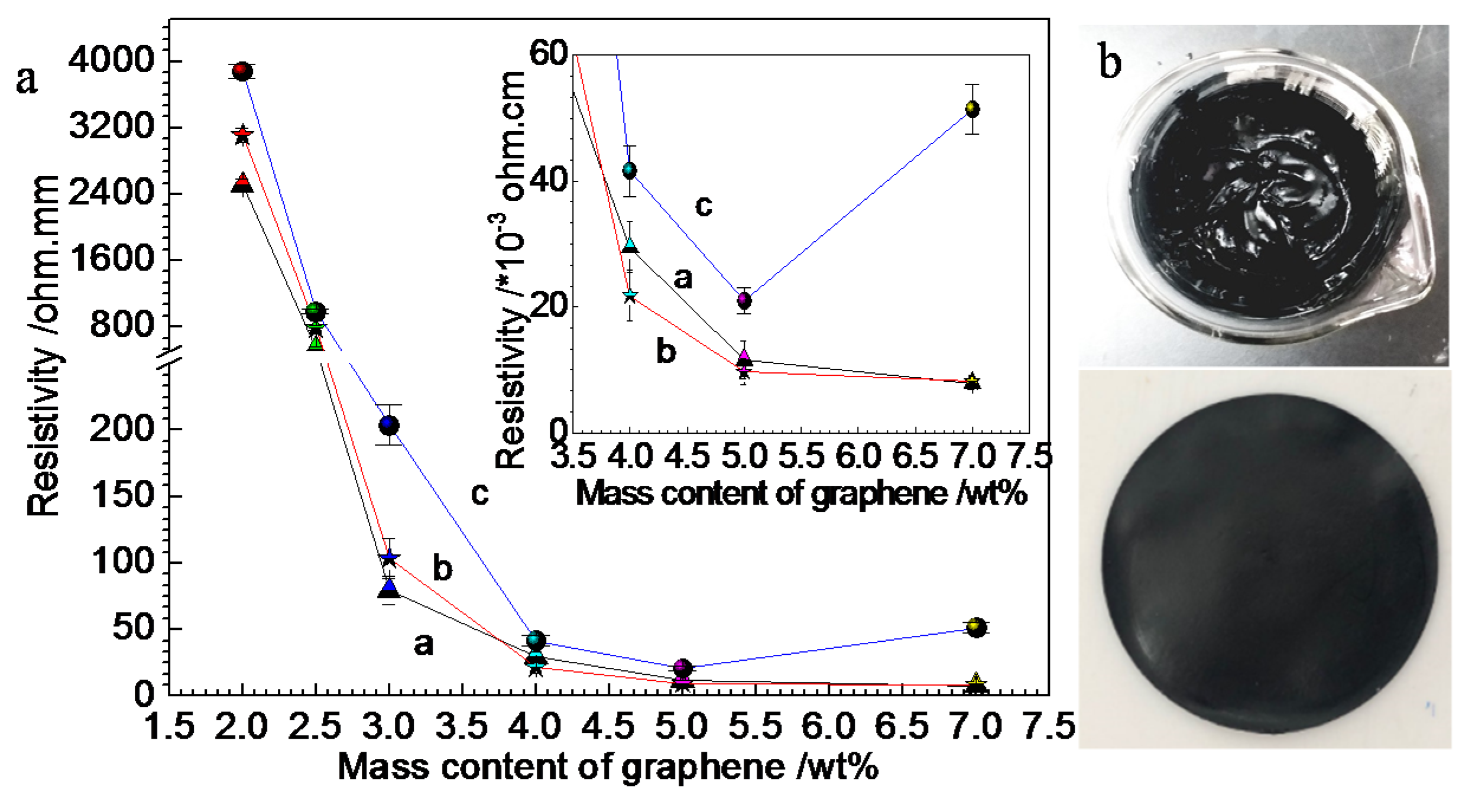
Few studies have reported the effect of the initial TPU solution concentration on the properties of the composite film. However, the viscosity of TPU solution is determined by the initial TPU solution concentration, which affects the dispersion of RGO in the composite film. We prepared TPU solutions with initial concentrations of 10, 20, and 30 wt%, respectively, and then added RGO/NCC slurries into the TPU solutions with different concentrations, respectively, according to the mass contents of RGO in the composite films of 0.2, 0.4, 0.8, 1.0, 1.5, 2.0, 2.5, 3.0, 4.0, 5.0 and 7.0 wt%, respectively. Figure 3a shows resistivities of RGO/NCC-TPU composite films with different mass contents of RGO and the initial TPU concentrations of 10 wt% (curve a), 20 wt% (curve b), and 30 wt% (curve c), respectively, and Figure 3b shows photos of the RGO/NCC-TPU slurry prepared with initial TPU concentrations of 20 and 5 wt% RGO (above) and the corresponding RGO/NCC-TPU composite film (below), respectively. The inset in Figure 3a is local magnification. When the RGO/NCC mass content of it ranges from 0.2–1.5 wt%, the composite films are non-conductive, so there are no data shown in Figure 3a. When the RGO/NCC mass content is 2.0 wt%, the resistivities of RGO/NCC-TPU composite films fabricated with the initial TPU concentrations of 10, 20 and 30 wt%, respectively, are 2509.1, 3109.1 and 3879.3 Ω·mm, respectively. With an increase of the RGO mass content, the resistivity of composite film decreases gradually. When the mass content of RGO/NCC is less than 4%, the lower the initial TPU concentration is, the lower the resistivity of the composite film is. When the RGO mass content reaches 4 wt%, the resistivities of RGO -TPU composite films fabricated with the initial TPU concentrations of 10, 20 and 30 wt%, respectively, are 29.5, 21.8 and 41.6 Ω·mm, respectively. Clearly, the resistivity of the composite film fabricated with the initial TPU concentration of 20 wt% is the lowest. As the mass content of RGO continues to increase, the resistivity of the composite film fabricated with the initial TPU concentration of 20 wt% remains minimal and reaches 8.1 Ω·mm when the mass content of RGO is 7 wt%. However, the resistivity of the composite film fabricated with the initial TPU concentration of 30 wt% increases to 51.4 Ω·mm when the mass content of RGO is 7 wt%. During heat treatment of the sample, as the solvent evaporated, the crosslinking reaction is carried out in the composite film, and the TPU matrix continues to shrink. This makes the RGO sheets more tightly overlapped and stacked. When the RGO mass content in the composite film reaches a certain value, the RGO in the composite film overlaps and stacks with each other, and the conductive networks are established in the film. As such, the composite film exhibits conductivity [28,29,30,31,32]. As the RGO mass content increases, more and more conductive networks in the film are formed and the conductivity of the composite film gradually increases. However, the excessive RGO in the slurry tends to form large agglomerations, which results in poor dispersion [21]. Typically, graphene is prone to aggregate and precipitate irreversibly in a variety of matrices due to its insolubility, van der Waals forces, and π-π stacking between RGO sheets [21]. Currently, the dispersion methods of RGO mainly includes physical dispersion, covalent bonding, and noncovalent bonding. In our experiments, a stirring treatment was utilized to disperse the RGO/NCC in the TPU solution. Although the stirring dispersion owns a simple operation, the dispersion rate of the RGO is low. Especially at a high mass content of RGO, the formation of aggregates of RGO is inevitable [21]. In addition, the lower the initial TPU concentration is, the lower the TPU solution viscosity is, which is not conducive to forming the compact stacking and overlapping structure of RGO sheets in the composite film. The higher the initial TPU concentration is, the greater the TPU viscosity is, which results in the difficulty of dispersion of RGO in the TPU solution and the formation of aggregates of RGO. We added commercial graphene sheets as conductive fillers into TPU solution and, when the mass content of graphene exceeded 5 wt%, the mixture could not be stirred. However, in this case, the mass content of RGO can reach 7 wt% because we used NCC to modify RGO. RGO was added into TPU in the form of slurry, which improved the dispersion of RGO in TPU solution.
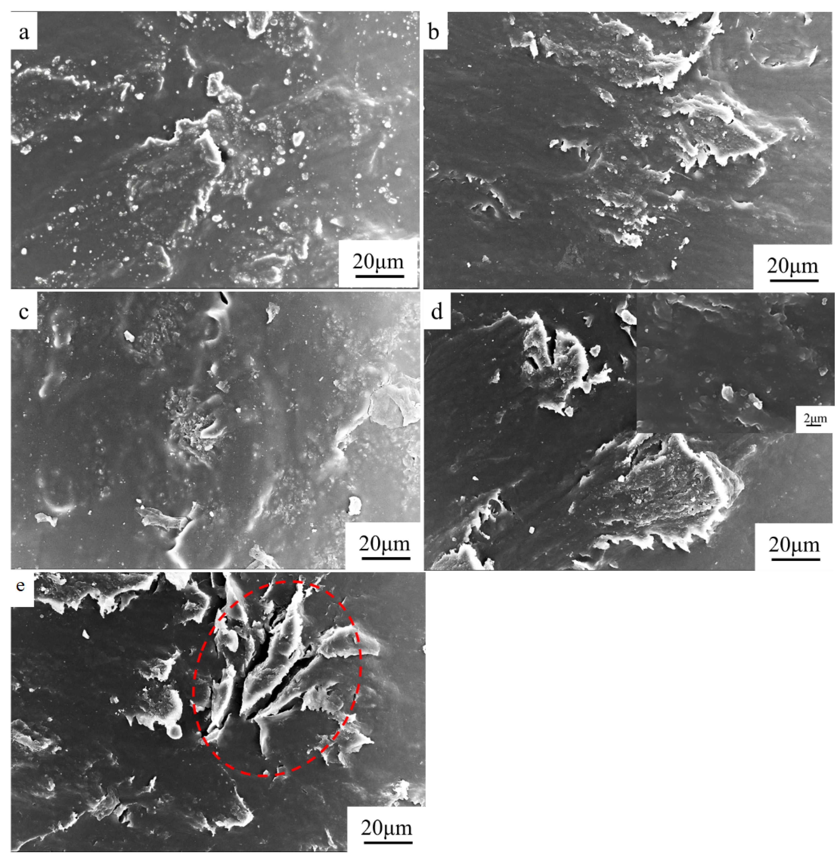
Figure 4 shows SEM images of surface morphology of the composite films prepared with the initial TPU concentration of 20 wt% and the mass content of RGO of 0.4, 1.5, 3.0, 5.0, and 7.0 wt%, respectively. It is clearly that the RGO/NCC are buried in the TPU matrices and exhibit grainy and rough characterization. With the increase of the mass content of RGO, the density of stacked RGO sheets increased, which is advantageous for forming the conductive pathways. When the mass content of RGO is 7.0 wt%, the clear cracks can be observed in the sample. This may be due to the higher content of graphene, which leads to greater internal stress in the composite film.
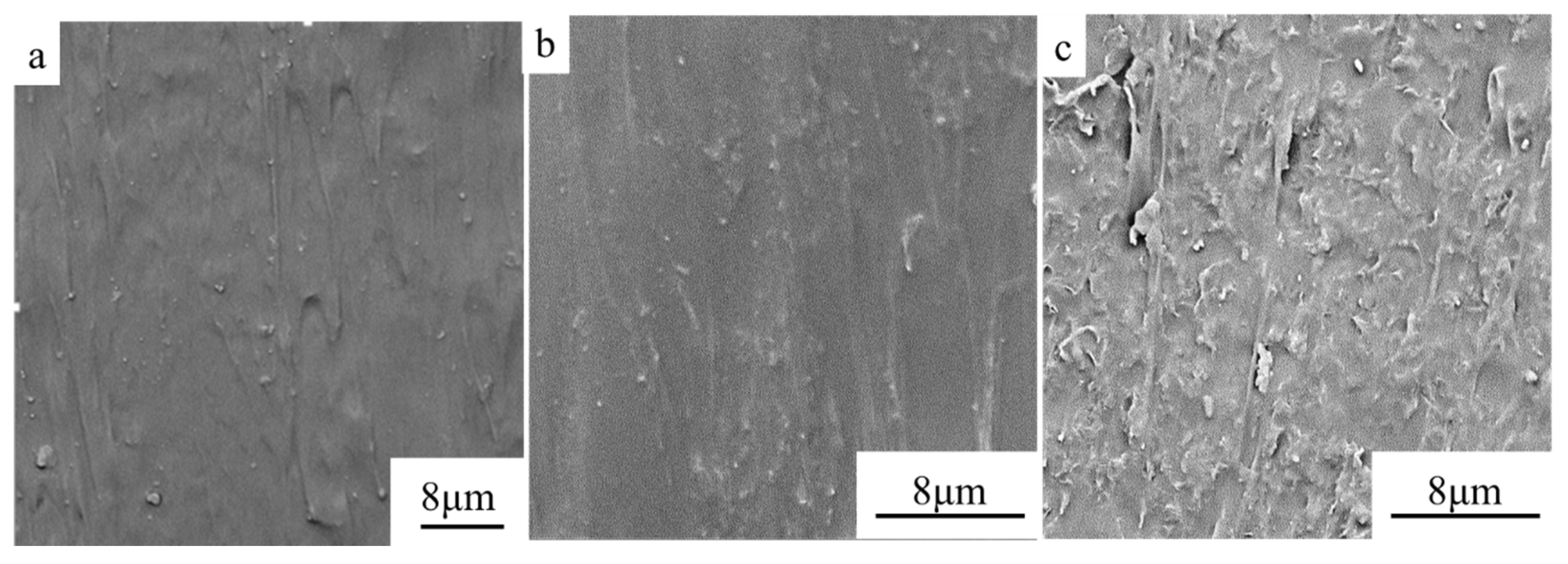
Figure 5 shows SEM images of the cross-section morphology of the composite films prepared with the initial TPU concentration of 20 wt%. The mass content of RGO of 1.5, 3.0 and 5.0 wt%, respectively. In the cross-section view surface of composite films, it clearly shows a smooth surface coated with TPU in the low mass content of RGO (Figure 5a,b). The RGO sheets dispersed and overlapped in the TPU matrices can be observed in the high mass content of RGO (Figure 5c). It indicates a good compatibility between the RGO/NCC and TPU matrices, which makes closer contacts between them, promotes forming some conductive pathways, and builds conductive networks. However, when the mass content of RGO increases to 5.0 wt%, RGO sheets are easy to form agglomerates in the polymer samples.
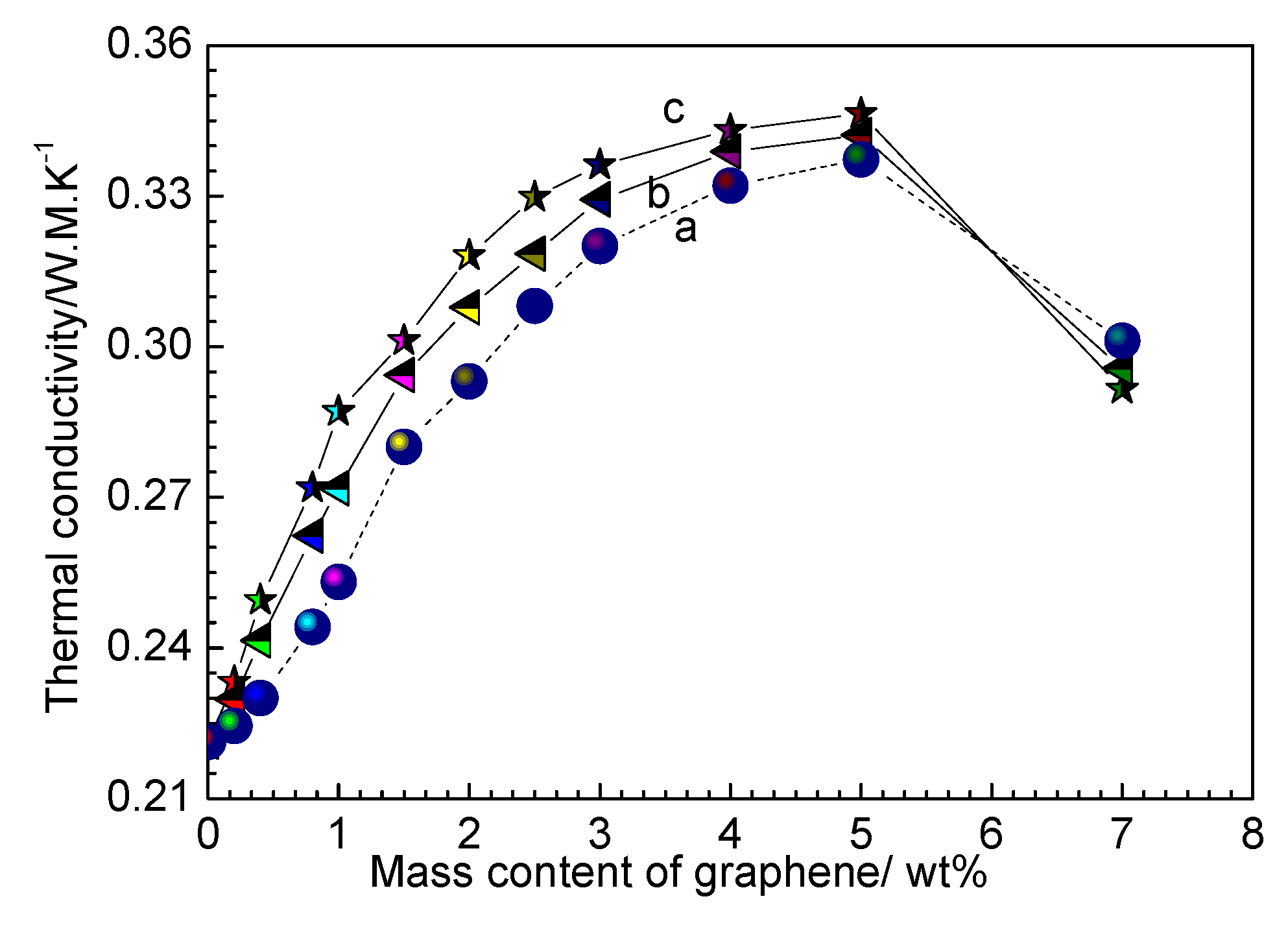
In order to reveal the effect of RGO on thermal conductivity of the composite film, we measured the thermal conductivity of the composite films with different mass contents of RGO and different initial TPU concentrations, as shown in Figure 6. The thermal conductivity of the pure TPU is about 0.2213 W·m−1·K−1 and the thermal conductivity of the composite film first increases and then decreases with the growth of the mass content of RGO in composite film. When the mass content of RGO reaches 5 wt%, the thermal conductivity of composite film fabricated with the initial TPU concentration of 30 wt% reaches a maximum of 0.3464 W·m−1·K−1, which increases by 56% when compared with that of pure TPU. When the mass content of RGO is less than 5 wt%, the thermal conductivity of the composite film with the same RGO mass content increases with the initial TPU concentration. However, when the RGO mass content is 7 wt%, the thermal conductivity of the composite film fabricated d with the initial TPU concentration of 30 wt% is the smallest. Many interfaces are produced when RGO sheets are added into TPU due to a very high specific surface area of RGO sheets [36]. These interfaces result in phonon scattering and introduce interfacial thermal resistance. RGO is a highly thermal conductive channel in the composite film. When the mass content of RGO is below the percolation threshold, RGO cannot connect together to form a thermal conduction pathway. In this case, the interfacial thermal resistance of RGO and TPU is the main factor determining the thermal conductivity of the composite film. While the mass content of RGO is above the percolation threshold, the heat in the composite film mainly transfers through the thermal conduction pathways due to the high thermal conductivity of RGO, and the thermal conductivity of the composite film increases significantly. However, when the mass content of RGO is too high, RGO sheets tend to form a large number of aggregates, which makes it impossible to form effective thermal channels, so that the thermal conductivity decreases [21,37,38,39].
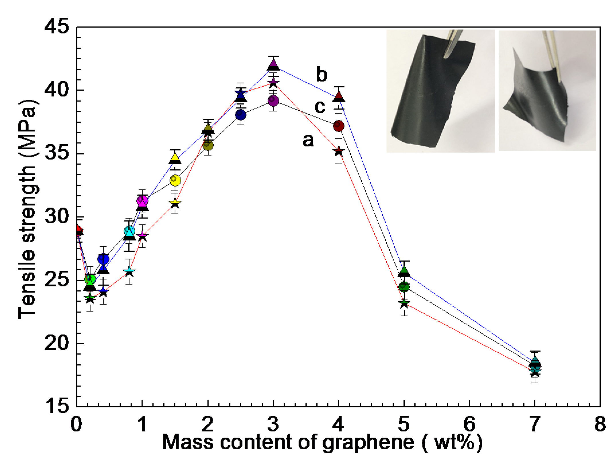
Figure 7 shows tensile strength of RGO/NCC-TPU composite films with different mass contents of RGO and the initial TPU concentrations of 10 wt% (curve a), 20 wt% (curve b), and 30 wt% (curve c), respectively. The insets in Figure 7 are samples. Graphene is often regarded as excellent reinforcing fillers of the composites due to outstanding mechanical performance. In this case, we can see that the tensile strength of the composite films first decreases (0.2 wt% RGO), then increases (≥ 0.4 wt% RGO), reaches the maximum until the RGO mass content is 3 wt%, and then decreases. The tensile strength of the composite films with mass contents of RGO of 3 wt% and the initial TPU concentrations of 20 wt% is the maximum of 43.2 Mpa, which increases by a factor of 1.5 (the tensile strength of the pure TPU is 28.9 MPa). There is no clear trend between the tensile strength and the initial TPU concentration of the sample when the RGO mass content in the composite film is less than 3 wt%, except that the tensile strength of the sample fabricated with the initial TPU concentration of 20 wt% is relatively high. The experimental results reveal that the mechanical property of TPU film can be improved by adding the appropriate amount of RGO. When the mass content of RGO is relatively low, the dispersion of RGO in the film is non-uniform and RGO in the film becomes the stress concentration point. This process results in a decrease in the mechanical property of the film. With the increase of the mass content of RGO, the dispersion uniformity of RGO in the film is also enhanced, which improves the TPU mechanical property. However, when the RGO mass content in the film is too high, the RGO aggregates degrade the mechanical property of the film [21].
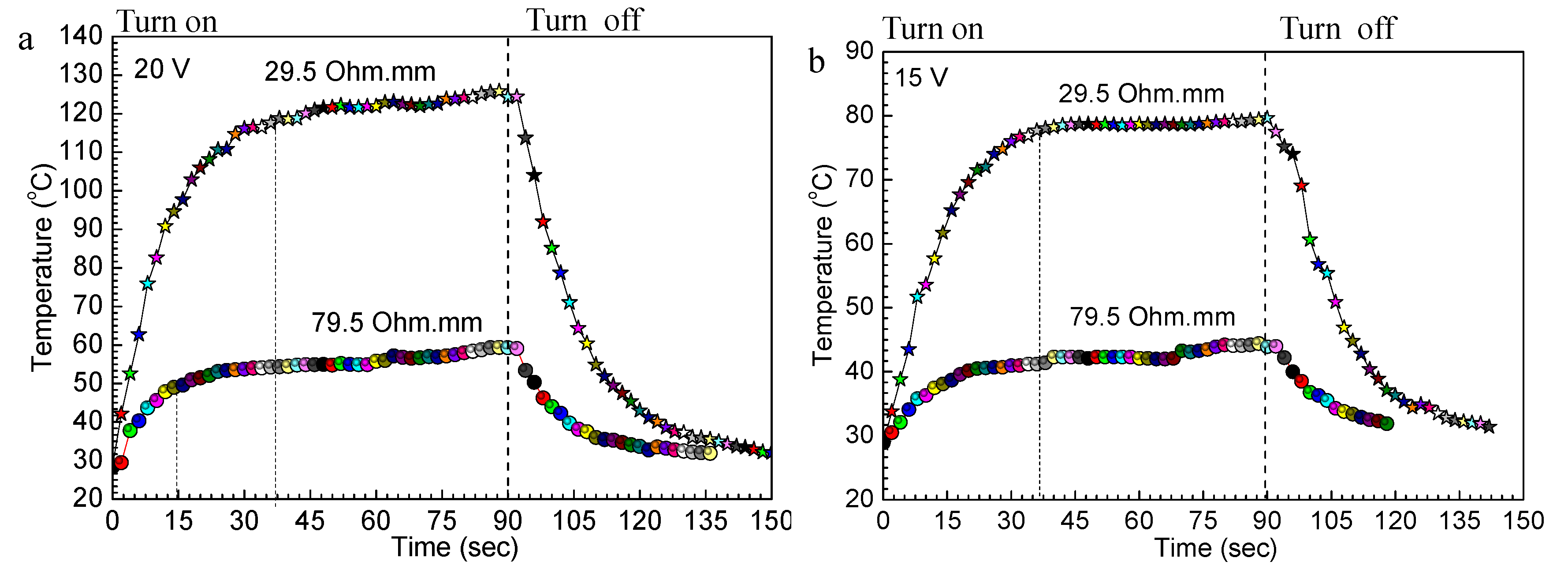
In recent years, the electrothermal response performance of conductive films has also aroused the interest of researchers due to the potential application of conductive film as a flexible electro-thermal heater [40,41,42,43]. In this study, we investigated the electrothermal response performance of the RGO/NCC-TPU conductive film by applying direct current (DC) voltage-stabilized power in a laboratory environment. The RGO/NCC-TPU conductive film was made through two clips coated with copper foil that contacted the film edges as electrodes. Figure 8 shows a plot of temperature versus time for the RGO/NCC-TPU conductive films with resistivity of 29.5 and 79.5 Ω·mm, respectively, under the operation for input voltage of 20 (Figure 8a) and 15 V (Figure 8b), respectively. The experimental results reveal that the temperature increases linearly in 10 and 20 s for the films of 79.5 and 29.5 Ω·mm, respectively, and, thereafter, the temperature increases slowly with time until it reaches a steady state temperature, which confirms the fast electrothermal response performance. The state temperatures of the films of 79.5 and 29.5 Ω·mm are 54.5 and 120.7 °C, respectively, under the operation for input voltage of 20 V, and are 42.4 and 78.3 °C, respectively, under the operation for input voltage of 15 V, respectively. The experimental results indicate that the efficient transduction of electrical energy into Joule heating is caused by the good conductivity of the composite film. The results, therefore, demonstrate that the composite film is suitable for applications in the field of the fast temperature switching with low input voltages. It can be seen from the above experimental results that the electrothermal response of the RGO/NCC-TPU conductive film is similar to that of the flexible transparent conductive AgNWs film [44]. However, under the same conductivity conditions, the thermal efficiency is low among flexible transparent conductive AgNWs film [44]. The reason may be that the Joule heating energy is consumed when the RGO transfers heat energy through the TPU matrices.

3.2. Superhydrophobic Conductive Composite Film of RGO/NCC-TPU

Due to the characteristics of TPU material, the RGO/NCC-TPU conductive film is susceptible to environmental humidity. We considered fabricating the superhydrophobic layer on the surface of the conductive film to improve the humidity effect of materials. Figure 9 shows the water contact angle (CA) of the RGO/NCC-TPU conductive films with different mass contents of RGO. The insets are photos of the water contact angle of the pure TPU and composite film with 4 wt% of RGO. The water contact angle of the pure TPU is about 124.90° and increases to 155.82° after adding 2 wt% of RGO into composite film, which displays a superhydrophobic characteristic. With the increase of the mass content of RGO in the film, the water contact angle of the composite film slightly increases and is 157.19° when the mass content of RGO in the composite film is 4 wt%. The hydrophobic F-POSS molecules deposits not only on the composite conductive film surface, but also penetrates deeply into the composite film. Therefore, the hydrophobicity of the conductive composite film is greatly improved.
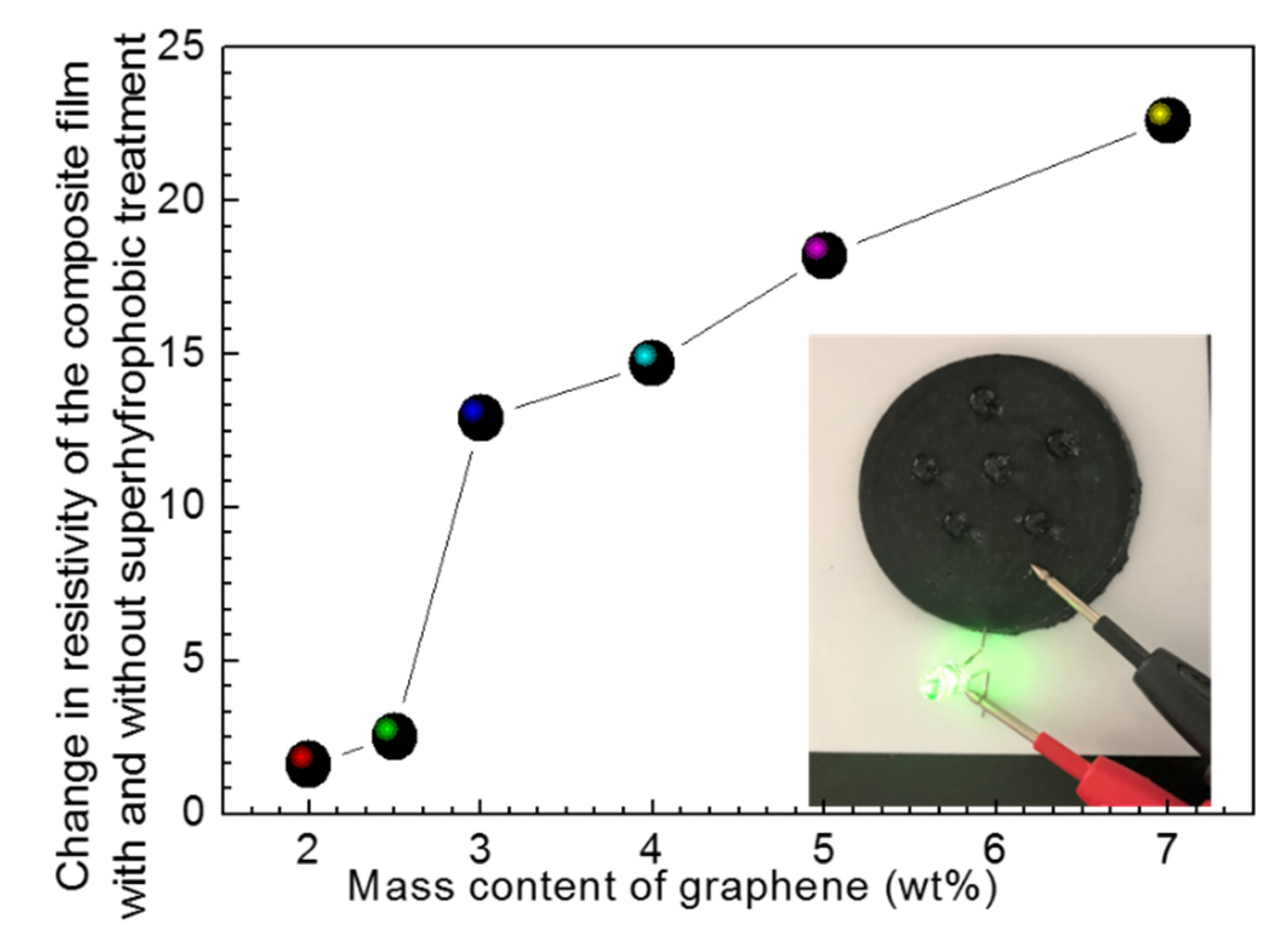
To demonstrate the effect of the superhydrophobic treatment on the conductivity of the RGO/NCC-TPU conductive film, we measured the resistivity of the composite film after superhydrophobic treatment, as shown in Figure 10. The inset is a photo of a light emitting diode (LED) device on the superhydrophobic conductive film. It is clear that the resistivity of the composite film after superhydrophobic treatment gradually increases with the mass content of RGO in the composite film. When the mass contents of RGO are 2 and 7 wt%, the resistivity of the superhydrophobic composite film increases by 1.6% and 22.6%, respectively. With the increase of the RGO mass content in the composite film, the conductivity of the composite film is affected by the F-POSS molecule as a non-conductive layer. To demonstrate the applicability of the superhydrophobic conductive composite film, we fabricated a LED device on the conductive film, as shown in the inset of Figure 10. A 0.5 W LED lamp fixed on the surface of the conductive film with superhydrophobic treatment is lighted, which indicates that the superhydrophobic conductive composite film still has good conductivity.

4. Conclusions

RGO/NCC-TPU flexible conductive composite films were prepared via a convenient blending method and their electrical and thermal properties and tensile strength and electrothermal response performance were investigated. The experimental results reveal that the electrical and thermal properties of the composite films are closely related to the initial concentration of TPU and the mass content of RGO in the composite film. The resistivity of the composite film with the mass content of RGO/NCC of 7 wt% and the initial TPU concentration of 20 wt% is the minimum of 8.1 Ω·mm. However, the thermal conductivity of the composite film with mass content of RGO/NCC of 5 wt% and the initial TPU concentration of 30 wt% reaches a maximum of 0.3464 W·m−1·K−1, which increases by 56% when compared with pure TPU. The tensile strength of the composite films with mass contents of RGO of 3 wt% and the initial TPU concentrations of 20 wt% reaches the maximum of 43.2 MPa, which increases by a factor of 1.5 (the tensile strength of the pure TPU is 28.9 MPa). The composite film has a fast electrothermal response, and the state temperatures of the films of 79.5 and 29.5 Ω·mm are 54.5 and 120.7 °C, respectively, under the operation for input voltage of 20 V, and are 42.4 and 78.3 °C, respectively, under the operation for input voltage of 15 V. The superhydrophobic composite conductive films were prepared by immersing the composite conductive film into F-POSS ethanol solution. The water contact angle of the superhydrophobic conductive composite film reaches 158.19 and the resistivity of the superhydrophobic composite film slightly increases and still has good conductivity.

Author Contributions

Y.W. led and designed the experiment and wrote the manuscript. Z.Z., J.Z., J.T., and P.W. performed the experiments. Y.Z. measured the microstructures of samples. K.W., J.Z., J.T., and P.W. analyzed the data. All authors have read and agreed to the published version of the manuscript.

Funding

This research was funded by [National Natural Science Foundation of China (grant nunbers (61671140) and Zhongshan Science and Technology Projects (2017A1016, 2018SYF10) and Guangdong “Climbing” Program (pdjh2020a0736).

Acknowledgments

The National Natural Science Foundation of China grant nunbers (61671140) and Zhongshan Science and Technology Projects (2017A1016, 2018SYF10) and Guangdong “Climbing” Program (pdjh2020a0736) financially supported this work.

Conflicts of Interest

The authors declare no conflict of interest. The funders contributed toward collecting results and editing the manuscript.

References

  1. Xu, C.; Hu, S.; Zhang, R.; Hu, H.; Ying, C.; Zhang, F.; Liu, Q.; Fu, X. Preparation and properties of flexible conductive polydimethylsiloxane composites containing hybrid fillers. Polym. Bulletin. 2019, 76, 6487–6501. [Google Scholar] [CrossRef]
  2. Cuttaz, E.; Goding, J.; Vallejo-Giraldo, C.; Aregueta-Robles, U.; Lovell, N.; Ghezzi, D.; Green, R.A. Conductive elastomer composites for fully polymeric, flexible bioelectronics. Biomater. Sci. 2019, 7, 1372–1385. [Google Scholar] [CrossRef] [PubMed]
  3. Xu, Y.; Yang, Y.; Yan, D.; Duan, H.; Zhao, G.; Liu, Y. Flexible and conductive polyurethane composites for electromagnetic shielding and printable circuit. Chem. Eng. Jl. 2019, 360, 1427–1436. [Google Scholar] [CrossRef]
  4. Maya, M.G.; George, S.C.; Jose, T.; Kailas, L.; Thomas, S. Development of a flexible and conductive elastomeric composite based on chloroprene rubber. Polym. Test. 2018, 65, 256–263. [Google Scholar] [CrossRef] [Green Version]
  5. Wang, Y.; Liu, P.; Wang, H.; Zeng, B.; Wang, J.; Chi, F. Flexible organic light-emitting devices with copper nanowire composite transparent conductive electrode. J. Mater. Sci. 2019, 54, 2343–2350. [Google Scholar] [CrossRef]
  6. Gu, X.; Li, B.; Li, F.; Zhang, K.; Guo, M. Transparent and flexible vermiculite–cellulose nanofiber composite membranes with high-temperature proton conduction. J. Mater. Sci. 2019, 54, 5528–5535. [Google Scholar] [CrossRef]
  7. Wang, Y.H.; Yang, X.; Du, D.X.; Zhang, X.F. A Comprehensive Study of High-Performance of Flexible Transparent Conductive Silver Nanowire Films. J. Mater. Sci. Mater. El. 2019, 30, 13238–13246. [Google Scholar] [CrossRef]
  8. Yang, X.; Du, D.; Wang, Y.; Zhao, Y. Silver Nanowires Inks for Flexible Circuit on Photographic Paper Substrate. Micromachines 2019, 10, 22. [Google Scholar] [CrossRef] [Green Version]
  9. Husameldin, A.E.; Sharul, A.K.R.; Xavier, C.; Mohamed, H. Flexible conductive fabric/E-glass fibre composite ultra-wideband antenna for future wireless networks. IET Microw. Antennas Propag. 2019, 13, 455–459. [Google Scholar]
  10. Ji, T.; Feng, Y.; Qin, M.; Li, S.; Zhang, F.; Lv, F.; Feng, W. Thermal conductive and flexible silastic composite based on a hierarchical framework of aligned carbon fibers-carbon nanotube. Carbon 2018, 131, 149–159. [Google Scholar] [CrossRef]
  11. Singh, B.P.; Nayak, S.; Nanda, K.K.; Singh, A.; Takai, C.; Takashi, S.; Fuji, M. Transparent, flexible, and conducting films based on graphene–polymer composites. Polym. Compos. 2018, 39, 297–304. [Google Scholar] [CrossRef] [Green Version]
  12. Xu, W.; Zhong, L.; Xu, F.; Shen, W.; Song, W.; Chou, S. Silver Nanowire-Based Flexible Transparent Composite Film for Curvature Measurements. ACS Appl. Nano Mater. 2018, 1, 3859–3866. [Google Scholar] [CrossRef]
  13. Zhang, X.; Wu, J.; Liu, H.; Wang, J.; Zhao, X.; Xie, Z. Efficient flexible polymer solar cells based on solution-processed reduced graphene oxide–Assisted silver nanowire transparent electrode. Org. Electron. 2017, 50, 255–263. [Google Scholar] [CrossRef]
  14. Wang, P.; Peng, Z.; Li, M. Stretchable Transparent Conductive Films from Long Carbon Nanotube Metals. Small 2018, 14, 1802625. [Google Scholar] [CrossRef] [PubMed]
  15. An, J.; Le, T.-S.D.; Huang, Y.; Zhan, Z.; Li, Y.; Zheng, L.; Huang, W.; Sun, G.; Kim, Y.-J. All Graphene-Based Highly Flexible Non-Contact Electronic Skin. ACS Appl. Mater. Interfaces 2017, 9, 44593–44601. [Google Scholar] [CrossRef] [PubMed]
  16. Li, D.; Han, T.; Ruan, H. Solution-Assembled Ordered Grids Constructed with Silver Nanowires as Transparent Conductive Electrodes. ACS Omega 2018, 7, 7191–7195. [Google Scholar] [CrossRef]
  17. Das, T.; Sharma, B.K.; Katiyar, A.K. Engineering in-plane silicon nanowire springs for highly stretchable electronics. J. Semicond. 2018, 39, 011007. [Google Scholar] [CrossRef]
  18. Sohn, H.; Woo, Y.S.; Shin, W.; Yun, D.J.; Lee, T.; Kim, F.S.; Hwang, J. Novel transparent conductor with enhanced conductivity: Hybrid of silver nanowires and dual-doped graphene. Appl. Surf. Sci. 2017, 419, 63–69. [Google Scholar] [CrossRef]
  19. Raji, A.-R.O.; Varadhachary, T.; Nan, K.; Wang, T.; Lin, J.; Ji, Y.; Genorio, B.; Zhu, Y.; Kittrell, C.; Tour, J.M. Composites of graphene nanoribbon stacks and epoxy for Joule heating and deicing of surfaces. ACS Appl. Mater. Interfaces 2016, 8, 3551–3556. [Google Scholar] [CrossRef]
  20. Kea, K.; McMasterb, M.; Christophersonb, W.; Singerb, K.D. Effects of branched carbon nanotubes and graphene nanoplatelets on dielectric properties of thermoplastic polyurethane at different temperatures. Compos. Part B 2019, 166, 673–680. [Google Scholar] [CrossRef]
  21. Liang, A.; Jiang, X.; Hong, X.; Jiang, Y.; Shao, Z.; Zhu, D. Recent Developments Concerning the Dispersion Methods and Mechanisms of Graphene. Coatings 2018, 8, 33. [Google Scholar] [CrossRef] [Green Version]
  22. Ghivela, G.G.; Sengupta, J. The Promise of Graphene: A Survey of Microwave Devices Based on Graphene. IEEE Microw. Mag. 2020, 21, 48–65. [Google Scholar] [CrossRef]
  23. Wei, Y.; Yang, R. Nanomechanics of graphene. Natl. Sci. Rev. 2019, 6, 324–334. [Google Scholar] [CrossRef] [Green Version]
  24. Pang, Y.; Yang, Z.; Xie, X.; Tao, L. Graphene Oxide Modified Porous Graphene for Aqueous Alcohol Detection. IEEE Sens. Lett. 2020, 4, 1–4. [Google Scholar] [CrossRef]
  25. Tung, T.T.; Nine, M.J.; Krebsz, M.; Pasinszki, T.; Coghlan, C.J.; Tran, D.N.H.; Losic, D. Recent Advances in Sensing Applications of Graphene Assemblies and Their Composites. Adv. Funct. Mater. 2017, 27, 1702891. [Google Scholar] [CrossRef]
  26. Korkmaz, S.; Kariper, İ.A. Graphene and graphene oxide based aerogels: Synthesis, characteristics and supercapacitor applications. J. Energy Storage 2020, 7, 101038. [Google Scholar] [CrossRef]
  27. Stankovich, S.; Dikin, D.A.; Dommett, G.H.B.; Kohlhaas, K.M.; Zimney, E.J.; Stach, E.A.; Piner, R.D.; Nguyen, S.T.; Ruoff, R.S. Graphene-based composite materials. Nature 2006, 442, 282–286. [Google Scholar] [CrossRef]
  28. Pham, V.H.; Cuong, T.V.; Dang, T.D.; Hur, S.H.; Kong, B.-S.; Kim, E.J.; Shin, E.W.; Chung, J.S. Superior conductive polystyrene-chemically converted graphene nanocomposite. J. Mater. Chem. 2011, 2, 11312–11316. [Google Scholar] [CrossRef]
  29. Dhakal, D.R.; Lamichhane, P.; Mishra, K.; Nelson, T.L.; Vaidyanathan, R.K. Influence of graphene reinforcement in conductive polymer: Synthesis and characterization. Polym. Adv. Technol. 2019, 30, 2172–2182. [Google Scholar] [CrossRef]
  30. Barjasteh, E.; Sutanto, C.; Nepal, D. Conductive polyamide-graphene composite fabric via interface engineering. Langmuir 2019, 35, 2261–2269. [Google Scholar] [CrossRef]
  31. Kim, J.T.; Kim, B.K.; Kim, E.Y.; Kwon, S.H.; Jeong, H.M. Synthesis and properties of near Ir induced self-healable polyurethane/graphene nanocomposites. Eur. Polym. J. 2013, 49, 3889–3896. [Google Scholar] [CrossRef]
  32. Huang, L.; Yi, N.; Wu, Y.; Zhang, Y.; Zhang, Q.; Huang, Y.; Ma, Y.; Chen, Y. Multichannel and repeatable self-healing of mechanical enhanced graphene-thermoplastic polyurethane composites. Adv. Mater. 2013, 25, 2224–2228. [Google Scholar] [CrossRef] [PubMed]
  33. Luan, Y.; Gao, F.; Li, Y.; Yang, J.; Hu, Y.; Guo, Z.; Wang, Z.; Zhou, A. Healing mechanisms induced by synergy of Graphene-CNTs and microwave focusing effect for the thermoplastic polyurethane composites. Compos. Part A Appl. Sci. Manuf. 2018, 106A, 34–41. [Google Scholar] [CrossRef]
  34. Li, A.; Zhang, C.; Zhang, Y. Thermal Conductivity of Graphene-Polymer Composites: Mechanisms, Properties, and Applications. Polymers 2017, 9, 437. [Google Scholar]
  35. Sakairi, N.; Suzuki, S.; Ueno, K.; Han, S.-M.; Nishi, N.; Tokura, S. Biosynthesis of hetero polysaccharides by acetobacter xylinum-synthesis and characterization of metalion adsorptive properties of partially carboxyl methylated cellulose. Carbohydr. Polym. 1998, 37, 409–414. [Google Scholar] [CrossRef]
  36. Kamisan, A.I.; Kamisan, A.S.; Ali, R.M.; Kudin, T.I.T.; Hassan, O.H.; Halim, N.A.; Yahya, M.F. Synthesis of Graphene via Green Reduction of Graphene Oxide with Simple Sugars. Adv. Mater. Res. 2015, 1107, 542–546. [Google Scholar] [CrossRef]
  37. Xu, P.; Loomis, J.; Bradshaw, R.D.; Panchapakesan, B. Load transfer and mechanical properties of chemically reduced graphene reinforcements in polymer composites. Nanotechnology 2012, 23, 3847–3856. [Google Scholar] [CrossRef] [Green Version]
  38. Garzón, C.; Palza, H. Electrical behavior of polypropylene composites melt mixed with carbon-based particles: Effect of the kind of particle and annealing process. Compos. Sci. Technol. 2014, 99, 117–123. [Google Scholar] [CrossRef]
  39. Hu, Z.; Li, N.; Li, J.; Zhang, C.; Song, Y.; Li, X.; Wu, G.; Xie, F.; Huang, Y. Facile preparation of poly(p-phenylene benzobisoxazole)/graphene composite films via one-pot in situ polymerization. Polymer 2015, 71, 8–14. [Google Scholar] [CrossRef]
  40. Burger, N.; Laachachi, A.; Ferriol, M.; Lutz, M.; Toniazzo, V.; Ruch, D. Review of thermal conductivity in composites: Mechanisms, parameters and theory. Prog. Polym. Sci. 2016, 61, 1–28. [Google Scholar] [CrossRef]
  41. Meng, X.; Chen, T.; Li, Y.; Liu, S.; Pan, H.; Ma, Y.; Chen, Z.; Zhang, Y.; Zhu, S. Assembly of carbon nanodots in graphene-based composite for flexible electro-thermal heater with ultrahigh efficiency. Nano Res. 2019, 12, 2498–2508. [Google Scholar] [CrossRef]
  42. Jiang, H.; Wang, H.; Liu, G.; Su, Z.; Wu, J.; Liu, J.; Zhang, X.; Chen, Y.; Zhou, W. Light-weight, flexible, low-voltage electro-thermal film using graphite nanoplatelets for wearable/smart electronics and deicing devices. J. Alloy. Comp. 2017, 699, 1049–1056. [Google Scholar] [CrossRef]
  43. Chang, H.; Jia, Y.; Xiao, L.; Chen, H.; Zhao, K.; Chen, Y.; Ma, Y. Three dimensional cross-linked and flexible graphene composite paper with ultrafast electrothermal response at ultra-low voltage. Carbon 2019, 154, 150–155. [Google Scholar] [CrossRef]
  44. Wang, Y.; Du, D.; Yang, X.; Zhang, X.; Zhao, Y. Optoelectronic and Electrothermal Properties of Transparent Conductive Silver Nanowires Films. Nanomaterials 2019, 9, 904. [Google Scholar] [CrossRef] [PubMed] [Green Version]
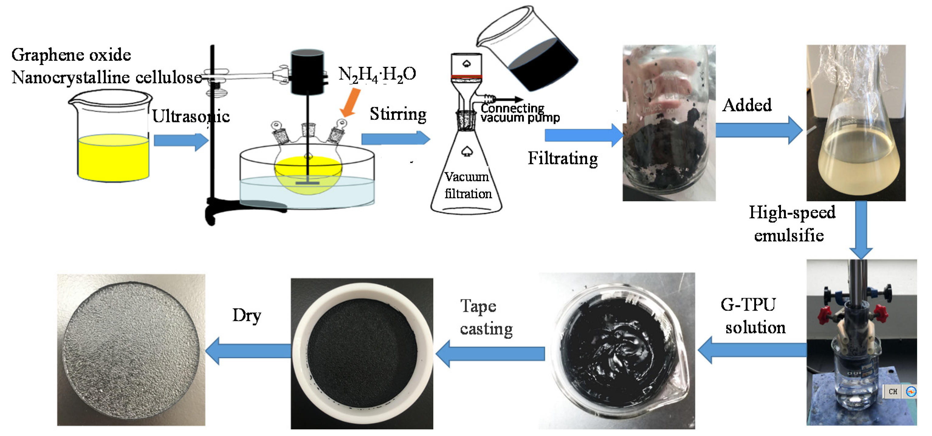
Figure 1. Schematic diagram of the fabrication process of the composite film.
Coatings 10 00400 g001
Figure 2. Differential scanning calorimetry (DSC) curves of pure thermopolyurethane (TPU) (a) and RGO/NCC-TPU composites containing graphene of 1.5 wt% (b).
Coatings 10 00400 g002
Figure 3. (a) Resistivities of RGO/NCC-TPU composite films with different mass contents of reduced graphene oxide (RGO) and TPU initial concentrations of 10 wt% (curve a), 20 wt% (curve b), and 30 wt% (curve c), respectively, and (b) photos of RGO/NCC-TPU slurry prepared with TPU initial concentrations of 20 wt% and 5 wt% RGO (above) and corresponding RGO/NCC-TPU composite film (below), respectively. The inset in Figure 3a is local magnification.
Coatings 10 00400 g003
Figure 4. Scanning electron microscope (SEM) images of surface morphology of the composite films prepared with the initial TPU concentration of 20 wt% and the RGO mass content of 0.4 wt% (a), 1.5 wt% (b), 3 wt%(c), 5 wt% (d), and 7 wt% (e), respectively. The inset in (d) is local magnification.
Coatings 10 00400 g004
Figure 5. SEM images of the cross-section morphology of the composite films prepared with the initial TPU concentration of 20 wt% and the graphene mass content of 1.5 wt% (a), 3.0 wt% (b), and 5.0 wt% (c), respectively.
Coatings 10 00400 g005
Figure 6. Relationship between thermal conductivity of RGO/NCC-TPU composite film and the mass content of RGO in the TPU initial concentration of 10 wt% (a), 20 wt% (b), and 30 wt% (c), respectively.
Coatings 10 00400 g006
Figure 7. Tensile strength of RGO/NCC-TPU composite films with different mass contents of RGO/NC and TPU initial concentrations of 10 wt% (curve a), 20 wt% (curve b), and 30 wt% (curve c), respectively. The insets in Figure 7a are samples.
Coatings 10 00400 g007
Figure 8. Temperature versus time for the RGO/NCC-TPU conductive films with resistivity of 29.5 and 79.5 Ω·mm, respectively, under the operation for input voltage 20 V (a) and 15 V (b), respectively.
Coatings 10 00400 g008
Figure 9. Water contact angle of RGO/NCC-TPU conductive films with different mass contents of RGO. The insets are photos of the water contact angle of the pure TPU and the composite film with 4 wt% of RGO.
Coatings 10 00400 g009
Figure 10. Change in resistivity of the composite films with and without superhydrophobic treatment. The inset is a photo of a light emitting diode device on the superhydrophobic conductive film.
Coatings 10 00400 g010