Article

Enhancing Electrical and Thermal Properties of Al6061 Parts by Electrophoresis Deposition of Multi-Walled Carbon Nanotubes

by
Juan Rodríguez-Salinas
*,
Marla B. Hernández
,
Luis Gerardo Cruz
,
Oscar Martínez-Romero
,
Nicolás A. Ulloa-Castillo
and
Alex Elías-Zúñiga
*
School of Engineering and Science, Tecnologico de Monterrey, Av. E. Garza Sada 2501 Sur, Monterrey, NL 64849, Mexico
*
Authors to whom correspondence should be addressed.
Coatings 2020, 10(7), 656; https://doi.org/10.3390/coatings10070656
Submission received: 18 May 2020 / Revised: 3 July 2020 / Accepted: 4 July 2020 / Published: 8 July 2020
(This article belongs to the Special Issue Electrodeposition of Thin Films for Energy Applications)

Abstract

:
The present research work focuses on depositing multi-walled carbon nanotubes (MWCNTs) onto aluminum parts to modify their electrical and thermal properties by an electrodeposition process (EDP). This film coated over the sample surface creates a network of high conductive thin layer that promotes free electron flow and heat-loss reduction. Experimental measurements on the metallic surface part show an increment of the electrical conductivity of 9.6% for the sample coated with 0.05 mg/mL of MWCNTs with a heat dissipation increase of 36%.

1. Introduction

The development of a new generation of advanced materials with enhanced physical properties, such as hardness, wear resistance, electrical and thermal conductivity, has been of great interest for industrial electrical applications for many years. For instance, there is a great need in energy sectors to have thermal conductance and electrical conductivity enhanced due to electrical plating so that when the currents flow through the material contact surface, the electrons will move thoroughly the contact points regularly are very small producing resistance to the free electrons flow (electrical resistance) and subsequently producing heat due to the free electrons passing restrictions (temperature rise). Therefore, creating a larger contact area that promotes a reduction of the electrical resistance and temperature rise on the material surface is desirable.
In this sense, plating is a conventional technology used to create a film of a conducting material over the surface contact of a metallic part that increases its electrical conductivity by reducing temperature rise because of the elimination of surface imperfections (see Figure 1b). Gold and silver are commonly materials used for plating metallic surfaces for improving electrical conductivity [1] and thermal conductance [2]. However, the physical properties of these materials limit their applications, since they cannot support high applied voltages and currents because of their melting-point temperatures (see References [3,4] and references cited therein).
In order to overcome these limitations, the present research work focuses on using carbon nanotubes (CNTs) to enhance the electrical and thermal properties of the metallic surface materials by an electrodeposition process (EDP) of a thin film of MWCNTs. This film coated over the sample surface could remove imperfections and create a network of highly conductive material that promotes free electron flow, reducing the heat produced on the contact surface, as illustrated in Figure 1b. Other undesirable defects, such as corrosion and surface roughness, could also be controlled.
The application of a thin layer of MWCNTs with almost null electrical resistance produces a path of free electrons over the surface of the metallic material enhancing its conductivity. The first article on depositing carbon nanotubes by electrophoresis process was published by Du et al. [5]. In this article, they found that the electrical conductivity of the electrodeposited film depends on the chiral angle and the diameter of the carbon nanotubes, since their electronic structure could change from conductive to semi-conductive due to the incorporation of functional groups. They concluded that the hydrogen adsorption by the carbon nanotubes might influence the electrical conductivity of the electrodeposited films. They also observed that the solvent composition greatly affects the microstructure of the deposited films [5].
Lim et al. [6] showed that the thickness of this thin film will influence the electrical resistivity. This observation was confirmed by Castro and co-workers by applying a CNT coating on the surface of aluminum wires [7]. They found that the electrical conductivity changes from 26.3 ± 7 S μm−1 to 45.3 ± 1 S μm−1, resulting in an increase of about 72%.
There exists great interest in several industrial sectors to enhance metal surface properties with nanotechnology employing technological resources that could be scaled into industrial settings for massive production. In this sense, carbon nanotubes (CNTs) have been widely used to improve material properties because of their exceptional mechanical characteristics, such as a Young’s Modulus of 1.7–2.4 TPa and high thermal conductivity of about 3000 W/mK with negligible electrical resistance [8,9]. Since CNTs experience low wettability into metal materials, this builds some difficulties that prevent their use on modifying metal substrates by conventional methods [10,11]. To overcome these difficulties, several processes and techniques have been reported in the literature to reinforce metallic powder materials with CNTs. In these techniques, the substrate is modified with the use of mechanical, chemical, electrical or magnetic forces that promote the insertion of the CNTs into the metallic powder material. By using mechanical process such as ball milling, Baski et al. [12] and Silvestre [13] inserted CNTs into metallic powder of different types. In these technologies, CNTs are homogeneously dispersed into the metallic powder by using water, alcohol, air, polymers and a suitable medium based on argon or nitrogen gas, to avoid the oxidation of the metallic powders during the attachment of the CNTs by the ball-milling process. Here, process parameters such as time, temperature, concentration, humidity and the production of oxidation, as explained by Chen et al [14], must be thoroughly controlled since they influence the final mechanical, electrical and thermal properties of the consolidated material [15,16].
One of the significant challenges associated with mechanical processes is to maintain the CNTs attached to the surface of the metallic powder particles [17,18]. In this sense, B. Gou et al. proposed to decorate with cupper nanoparticles the MWCNTs, to maximize their wettability into the aluminum matrix [19]. Once the MWCNTs are attached to the metallic powder, they are sintered with the use of furnaces or spark plasma process [20,21] to consolidate the part. This sintered part is then post-processed by applying the hot extrusion process to produce the aluminum composite part [22,23,24,25]. Of course, other methods such as the stirred [26], electrophoretic deposition [27,28] and a sandwich technique [29] could be used to attach MWCNTs on the metallic consolidated part.
Electrodeposition is an alternative technique to deposit MWCNTs over the surface of a metallic substrate. This process is based on the application of an electrical field for depositing a thin layer of MWCNTs over a metallic substrate immerse into an aqueous solution that is electrically charged. The functionalized MWCNTs move in the aqueous solution from the cathode to the metallic part, creating a thin layer on its surface. A good explanation of the steps followed to attach MWCNTs to the surface of metallic parts is provided by Thomas and co-workers [30]. There, a high voltage was applied between the aqueous solution with dissolved MWCNTs and the substrate, to promote the adherence of the nanostructures to the metallic surface.
The effectiveness of the electrophoretic deposition method in different materials such as nickel, stainless steel, braze and aluminum series 6000 has been studied by Sun [31], Fraczek-Szczypta et al. [32], Ramalingam [33], Selvakumar [34] and Madhu [35], respectively. In this sense, Castro and co-workers reported a 160% increase in the electrical conductivity of commercial aluminum wires reinforced with a concentration solution of 0.05 mg/mL of single-wall carbon nanotubes (SWCNTs) [5]. Similarly, Xu found that electrical resistivity at room temperature of commercial aluminum increases slightly with increasing volume fraction of the carbon nanotubes [36]. These properties could be modified by controlling the thickness, homogeneity and the shape of the surface on which the carbon nanotubes were deposited [37,38]. Of course, improvement of the metallic surface electrical and thermal properties depends upon on controlling the process parameters such as soaking time, voltage applied, carbon nanotubes concentration solution (water, molten salt and alcohols) [39,40], nanotubes direction [41] and shape of the container, to name a few.
In this work, a process for enhancing the surface electrical and thermal properties of aluminum 6061-O based on the electrophoresis deposition (EPD) is used. This process consists, basically, of two steps: (i) Functionalized multi-walled carbon nanotubes are added to a liquid solution and are forced to move under the action of an electrical field; and (ii) the electrically charged MWCNTs move toward the substrate, to be attached on the material surface. A temperature methodology was set to measure experimentally the thermal performance of the electrodeposited multi-wall carbon nanotubes on samples of Al6061. To the best of the author’s knowledge, this is the first paper that deals with thermal properties after the deposition of carbon nanotubes in aluminum metallic parts.
To better understand how EDP works, Section 1 provides a brief introduction of this process. Section 2 of the manuscript focuses on explaining the steps followed in this work to electrodeposit MWCNTs in Al6061-O material samples. In Section 3, aspects related to electrical and thermal conductivity obtained from the coated Al6061 material samples are addressed according to ASTM standard E1004—17 and safety UL 489 standards. Finally, the main findings of this research will be summarized in Section 4.

2. Materials and Methods

Commercial-grade multi-walled carbon nanotubes (MWCNTs) (carbon basis > 95%, diameter between 20 and 30 nm, and length between 10 and 30 μm) were purchased from Nanostructured and Amorphous Materials (Katy, TX, USA). Nitric acid (HNO3) and sulfuric acid (H2SO4) were purchased from Sigma-Aldrich, Toluca, México. All materials were used without any further purification. The MWCNTs were functionalized to ensure good adhesion on the substrate. For functionalization, the MWCNTs were poured into a mixture of HNO3-H2SO4 (30–70%, respectively) and magnetically stirred for 6 h, at ambient temperature. The functionalized MWCNTs were separated from the residual acid by repeated washing cycles with distilled water and centrifugation until neutral pH was achieved. Finally, the MWCNTs were dried at 100 °C, to remove water and humidity. The incorporation of carboxyl functional groups on MWCNTs induces a negative charge on them, promoting their mobility and good adhesion on the substrate surface [42]. The dispersion of MWCNTs in an aqueous solution of deionized water (0.05 mg/mL and 0.2 mg/mL) was carried out through an ultrasonic homogenizer tip (Cole-Parmer, Ultrasonic Processor), as described in the manuscript. The ultrasonic tip was operated at 35% of the maximum power 750 Watts, giving a total power of 262.5 Watts. All solutions were sonicated, applying such power during 2 min, to achieve good deagglomeration and dispersion. The experimental parameters used for MWCNT dispersion were performed in a time interval in which any additional surface modification in the acid-treated MWCNT surface is not expected, as reported by Arrigo [43].
The electrophoresis was performed in an aluminum cylindrical container used as a cathode. The aluminum 6061-O was manufactured to obtain samples with dimensions of 4 cm × 1 cm × 3 mm, which were used as the anode. The electrodeposition was performed by considering a bias voltage of 3, 5, 10 and 20 V and varying the deposition time in 5, 10 and 20 min. To ensure that the layer deposited on the substrate is uniform, the aqueous solution used for the EPD must have a high negative zeta potential, which is obtained for a pH value of 7. Then, with the help of a Zeta sizer apparatus (Malvern, Panalytical, Malvern, UK), the solution was analyzed. It was found that the solution mixed with MWCNTs has a zeta potential of −34 mV, which is enough of an electro negative charge to produce the electrodeposition on the surface, as shown in Figure 1a. The thermograms show that the temperature degradation for pristine MWCNTs occurs around 600 °C, while for the functionalized carbon nanotubes, the loss of mass due to the oxidation of the functional groups occurs under 400 °C. The measurements shown in Figure 1b were performed by using nitrogen as purge gas, with a heating rate of 10 °C/min and in a temperature range from 50 to 1000 °C.
Based on this information, it is possible to have a successful EDP since the MWCNTs are stable and able to suspend in the aqueous solution. Once the MWCNTs were properly dispersed, the solution was poured into the container. Then, a DC system power supply (6553A Agilent, Santa Clara, CA, USA) was connected to the anode (sample) and the cathode (container) to apply voltage for the previously selected deposition time. Finally, the MWCNTs-coated substrate was allowed to dry for further characterization. A schematic of the process setup system is shown in Figure 2.
The morphology characterization of the electrodeposited samples was carried out through a SEM (ZEISS model EVO MA 25, Oberkochen, Germany) microscope, using an accelerating voltage of 25 kV and a work distance of 10 mm. The surface morphology characterization was investigated by analyzing secondary electrons images, and the analysis composition was investigated by taking backscattered electrons images. The structural characterization was carried out by using a PanAnalytical (X’Pert Pro PW1800, Malvern, UK) system. The measurements were performed by using Cu-Kα radiation in a range of 2θ range of 10°–80°, with a scanning rate of 2°/min and operating the XRD system at 45 mA and 40 kV.
To determine the electrical conductivity over the surface of the coated Al6061 material samples, the millivolt-drop technique was used. Thus, metallic tips were placed on both edges of the samples, to generate the current flow, and then the voltage drop was measured in the middle of the sample surface, with the help of an Agilent Technologies U3402A multimeter (Santa Clara, CA, USA). The collected data were analyzed by considering the International Annealed Copper Standard (IACS). Thermal performance was investigated by applying an electrical current of 10 A, to induce heat on all the samples, using a DC Power Source (Agilent 6553 A). The temperature measurement was performed every 30 s for a total of 20 min, using a digital thermocouple with its tip in contact within each sample. The experimental setup was placed inside a transparent polymer box, to increase the accuracy of the recorded data by avoiding external humidity and undesirable temperature changes due to the surrounding environment.

3. Results

3.1. SEM Analysis

The quality of the film and the dispersion of the MWCNTs deposited on the substrate is influenced by the parameters’ values used during the EPD. The morphology of the MWCNTs deposited on the sample surface was studied by scanning electron microscopy (SEM), as shown in Figure 3. The micrograph of the Al6061 sample, as received, is shown in Figure 3a,b, showing some defects on the sample surface. The corresponding micrographs for MWCNTs electrodeposited are shown in Figure 3c,d. Such images correspond to MWCNTs electrodeposited by using the experimental parameters of 3 V during 5 min and considering the solution at 0.05 mg/mL. Notice from the images that the MWCNTs are well dispersed on the surface, showing the presence of low carbon nanotube agglomerations. A summary of the parameters used in the EDP is listed in Table 1.
For the sample surface coated with the highest concentration of MWCNTs and higher amount of voltage applied, the material deposited on the sample surface exhibits a higher packing density of carbon nanotubes due to the higher mobility produced by the large electrical field generated during the EDP; this produces a faster deposition of MWCNTs that creates disorganized agglomerates [45]. These observations agree with those reported in References [5,46]. Furthermore, Basu et al. [47] found that the formation of particulate films on the electrode is a kinetic phenomenon, since the accumulation rate of particles influences their packing behavior in coatings.
For higher applied electric fields, the MWCNTs suspension experiences turbulence, and then the deposited coating is disturbed by the surrounding suspension flows. Thus, the MWCNTs move at a faster rate and cannot be deposited uniformly on the sample surface, forming a close-packed agglomerate. Therefore, it can be concluded that the deposition rate and the morphology of the deposited MWCNTs are influenced by the applied electrical voltage.

3.2. X-ray Diffraction (XRD)

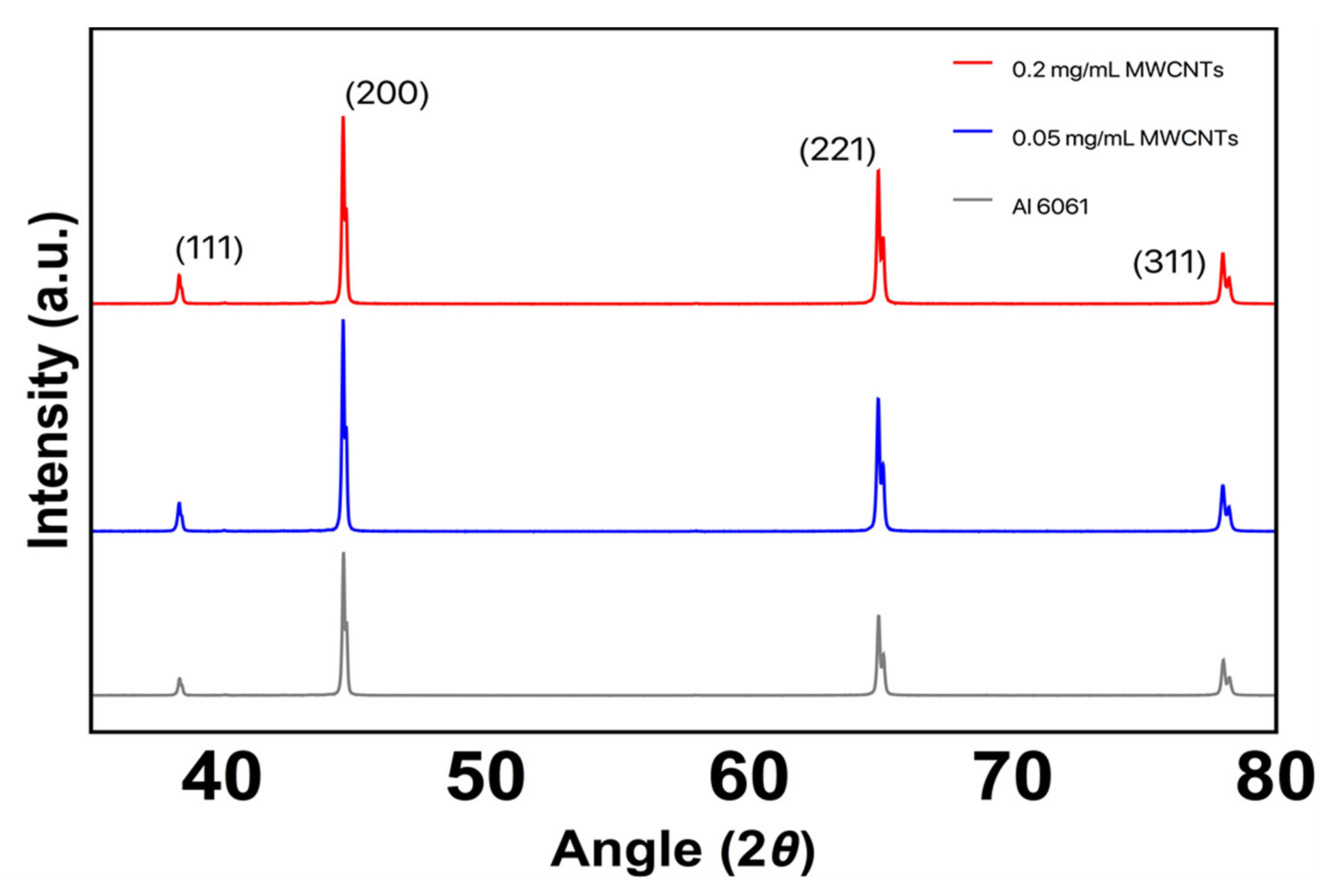
The diffractograms for electrodeposited Al6061 specimens in solutions at 0.05 and 0.2 mg/mL are shown in Figure 4. The results show peaks around 38.3°, 44.5°, 64.8° and 77.9°, corresponding to (111), (200), (221) and (331) planes. These peaks are characteristic of the Al face-centered cubic (FCC) unit cell. The diffractograms show no presence of the characteristic (002) plane for carbon nanostructures around 27°; the latter is due to the low content of MWCNTs deposited in the electrodeposited Al6061 specimens. It is possible to note that the electrodeposited samples do not present any considerable modification in the Al6061 structure.

3.3. Roughness Measurements: Surface Characterization

The samples’ surface roughness was measured by an Alicona Infinite Focus microscope, following the ISO 4288 norm, and by considering the apparatus parameters of 700 μs of brightness, a contrast of 4, objective overview of 50X, vertical resolution of 0.60 μm and lateral resolution of 6 μm. The Roughness Average (Ra), Root Mean Square Roughness (Rq) and the Average Maximum Height of the Profile (Rz) were measured to analyze the surface roughness of the Al6061 as received, versus samples coated by EDP in a solution with 0.05 mg/mL of MWCNTs at two voltage ranges of 5 and 20 volts. Notice from Table 2 that the lowest average roughness values are attained in the samples coated with 5 volts.

3.4. Electrical Conductivity

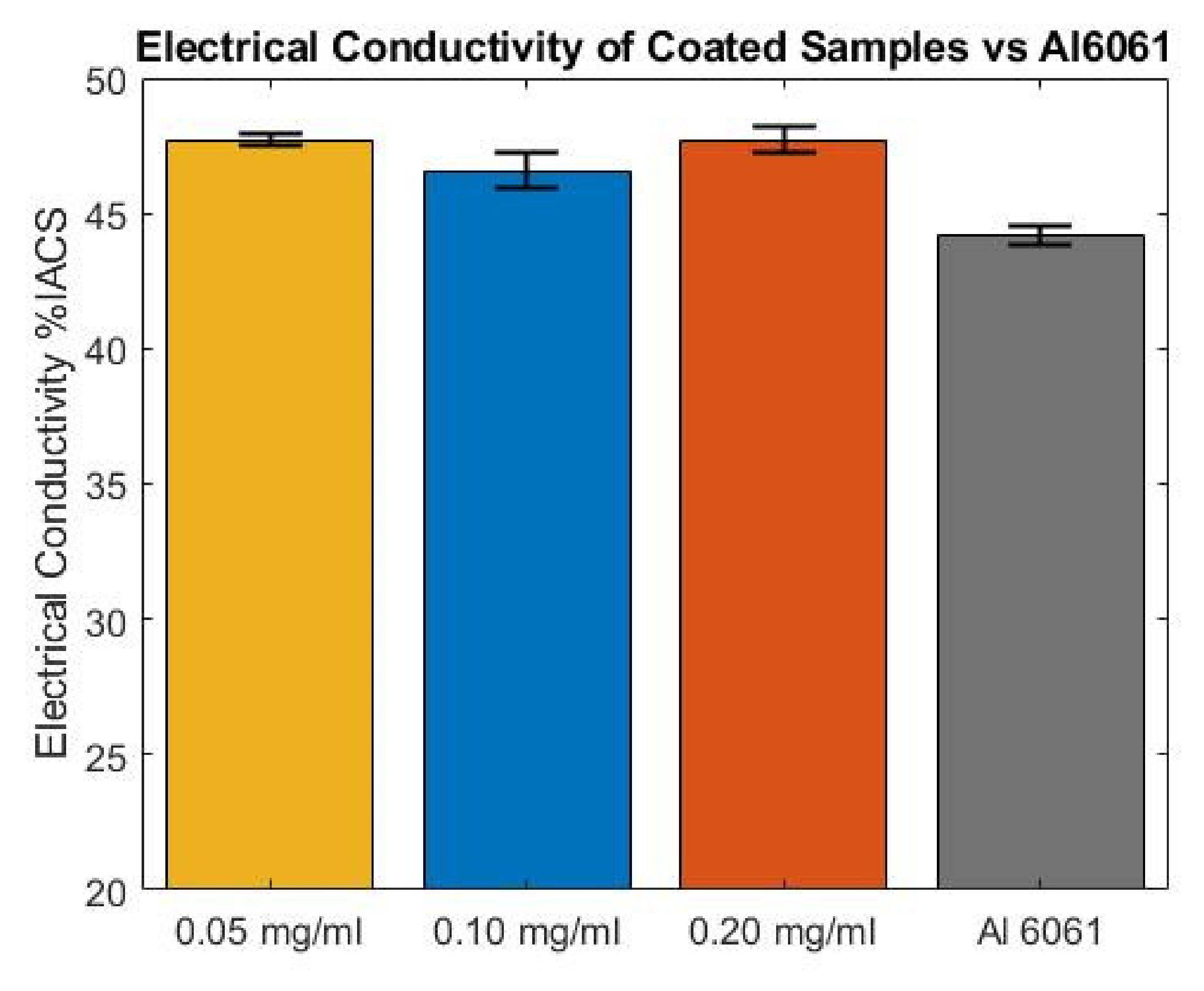
The electrical conductivity of metallic materials is associated with their resistance to electrons’ flow. The voltage drop across a section when an electric current is applied through the samples provides a method to indirectly obtain the electrical resistivity. In fact, the millivolt measurements registered through this methodology can be analytically converted to units related to electrical resistivity in ohms or conductivity, as claimed by the International Annealed Copper Standard (IACS), where the closest value to 100% represents a conductivity similar to the copper reference material. Here, the millivolt drop was obtained when a DC current of 10 A was applied through the sample. Nine measurements of the voltage across the middle section of the samples surface were collected. The recorded values were converted to electrical resistivity by using Ohm’s law. The electrical conductivity in IACS was obtained by analytical methods based on the electrical conductivity of the material. Statistical data of the electrical performance of the material samples subjected to different EPD parameters values are shown in Figure 5. Notice from Figure 5 that the average surface electrical conductivity measured was 47.7, 46.57 and 47.7, with a standard deviation of 1.93, 2.51 and 0.77, respectively. This represents an enhancement by a percentage of 9.6%, 7% and 9.6%, respectively, concerning the reference material, when MWCNTs are electrodeposited in a solution with concentrations of 0.05, 0.10 and 0.20 mg/mL.
The increment of the surface electrical conductivity can be related to the decrease in electrical resistance due to the deposition of thin films of MWCNTs onto the sample’s surface. The MWCNTs are well-known for their superior electrical capabilities, exhibiting a negligible electrical resistance mainly due to the tunneling effect produced by their lower resistance to the electrons flux. The distribution, concentration and dispersion of the CNT electrodeposited over the metallic surface produce a conductive network above a critical concentration of nanofiller known as percolation threshold [48]. The results obtained in this experimental work concluded that, even for the lowest solution concentration, it is possible to produce a thin conductive film of CNT over the metallic surface that is capable of overcoming the percolation threshold that enhances the electrical properties of the thin-film-coated metallic surface. In other words, the electrical properties on the surface of the aluminum samples are mainly affected by the chirality, length and electrical valence of the CNT, deposited due to the parameters selected during the deposition of the CNT thin film.
The deposition of MWCNT thin film on the metallic surface is a technique that promotes the electrons’ flow, reducing their transportation resistance across the metallic substrate. Since the chirality of the industrial grade MWCNTs is not controlled at all, the MWCNT thin film deposited over the metallic surface overcomes the percolation threshold because of the tunneling effect, enhancing the electrically conductive capabilities in the metallic material [48].
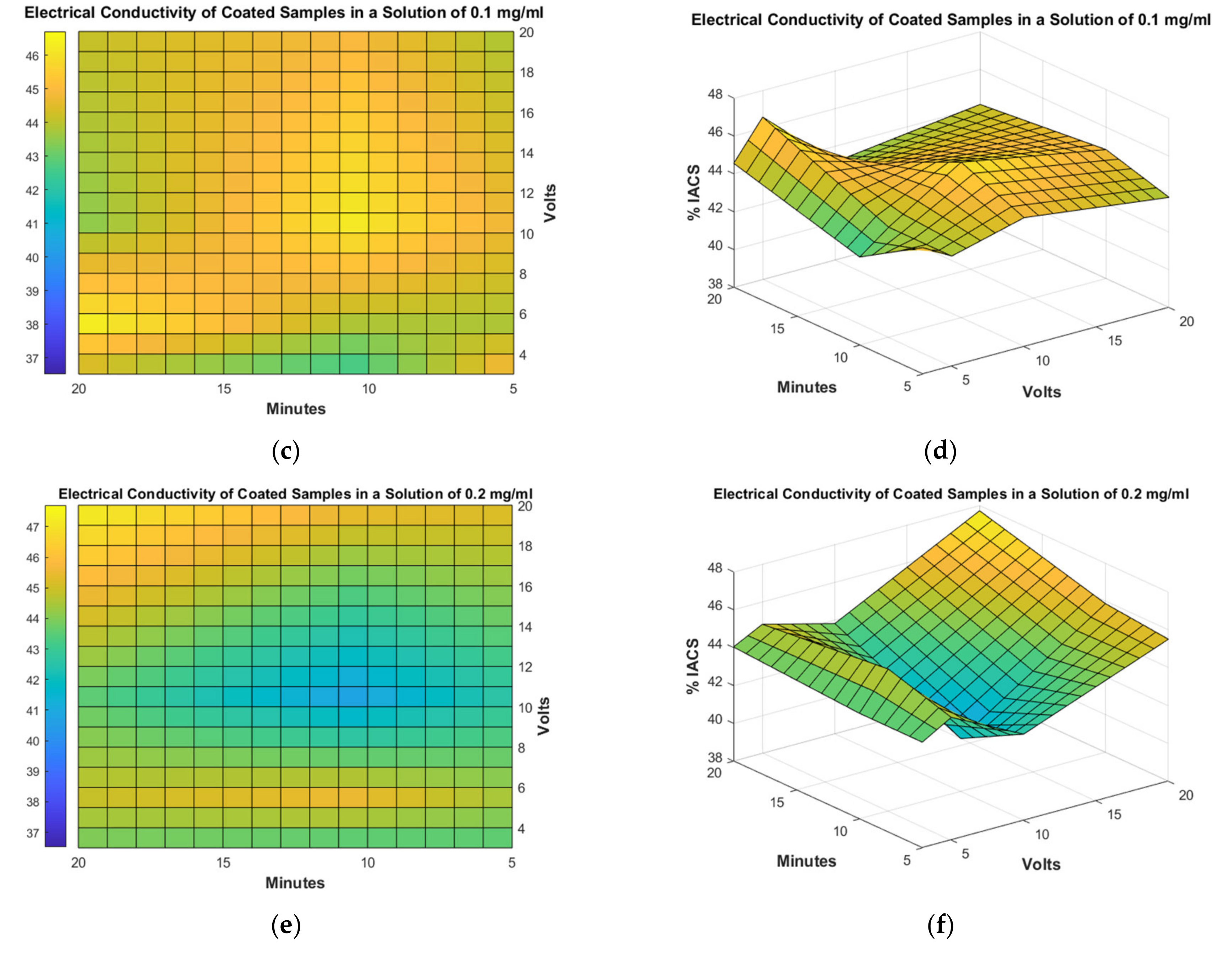
Figure 6 shows the %IACS based on the deposition time over voltage applied for the different concentrations of MWCNTs used. For instance, for a concentration’s solution of 0.05 mg/mL of MWCNTs, the electrical conductivity increases for lowest deposition times and applied voltages, as shown in Figure 5. In fact, the control of these parameters raises the surface conductivity when a thin film of MWCNTs is deposited over the substrate surface. The application of low voltages produces a small electrical force that encourages the displacement of the longest and negative-charged MWCNTs in the sparse concentration solution, for their attachment to the metallic surface. Feng et al. found an enhancement of the electrical properties of the coated material when longer and straight MWCNTs are deposited to the surface substrate [49] and claimed that MWCNTs’ physical properties enable them to reduce the percolation threshold of the modified material, as confirmed by Deng [50]. Moreover, notice from Figure 6d,f that for higher applied voltages and solution concentrations of MWCNTs deposited over the surface substrate, the electrical conductivity increases because of the large number of carbon nanotubes that are attached, at a constant rate, to the metallic surface due to the large deposition time that produces a dense film of a combination of MWCNTs with different chiralities, as explained by Wang [51]. Thus, the dense mixture of MWCNTs deposited will provide an electrically conductive path that allows the free electrons to flow with less electrical restrictions.
EPD parameters such as deposition time and applied voltage modify the performance of the electrical conductivity of the coated specimen. Statistical tools like Main Effect Analysis exhibit the influence of these parameters on the electrical enhancement of the substrate. Figure 7 shows EDP parameter values that produce the most repeatable and stable process. From this statistical analysis, the film deposited over the specimen in a concentration solution of 0.10 mg/mL of MWCNTs produces a sustained rate and homogeneous surface deposition of MWCNT. Furthermore, the applied voltage of 5 V encourages the deposition of a dispersed film of long MWCNTs over the surface, while the longer deposition times produce a dense layer of MWCNTs that will overcome the natural chirality of commercial-grade carbon nanotubes. The resulted thin film improves the sample electrical performance for a best-distributed relation of thickness vs. entanglement of the thin film of MWCNTs deposited over the specimen surface. Notice from Table 1 that the deposition time and the concentration of MWCNTs have a weak influence over the %IACS values when compared to the influence of varying the voltage values. These data agree with experimental characterizations of the coated aluminum samples shown in Figure 3, since the applied voltage has a direct impact on the distribution of MWCNTs all over the samples surface.

3.5. Thermal Results

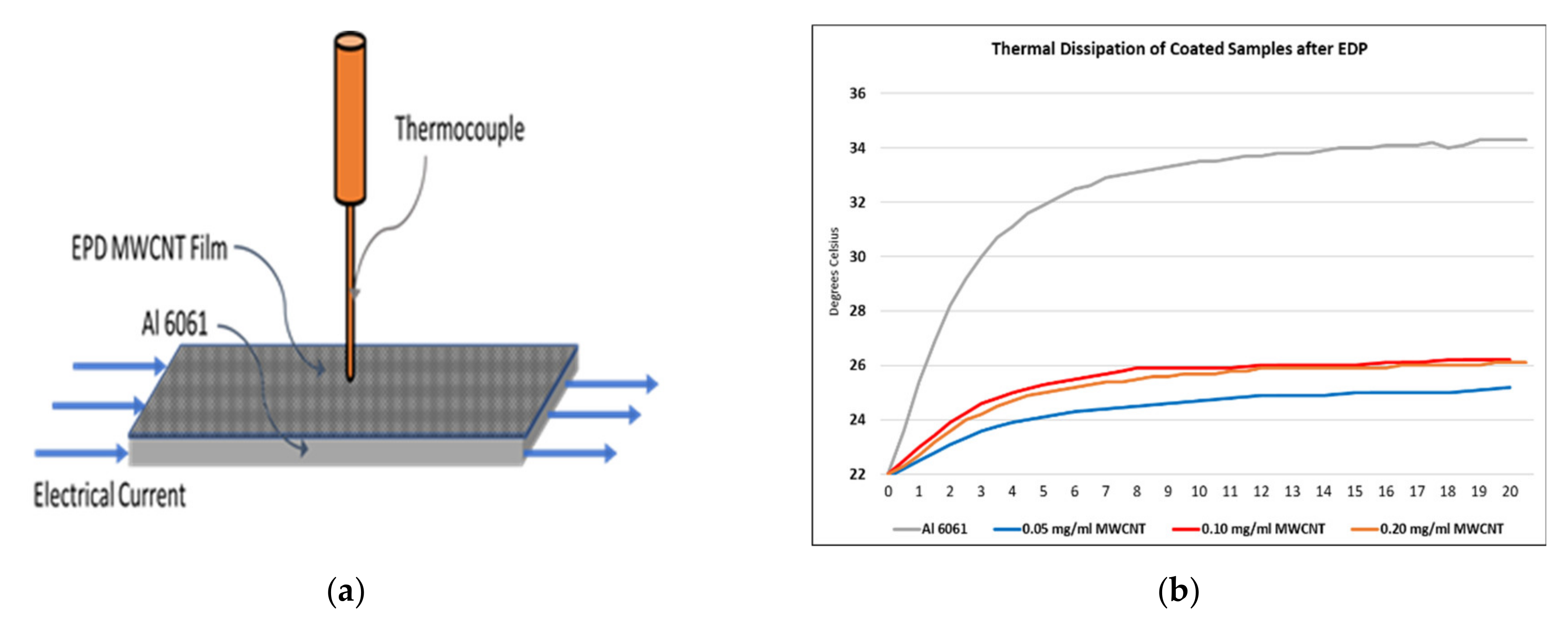
A temperature methodology was used to measure, experimentally, the metallic surface samples’ thermal performance of the nano-enhanced material. This methodology requires the application of an electrical current of 10 A over the specimen surface that produces an increment on its temperature. Then, the temperature rise is registered in three samples, every 30 s, for 20 min, using a thermocouple attached at the center of each surface, as shown in Figure 7a. Experimental measurements, shown in Figure 7b, indicate a surface temperature rise of 34 °C for the uncoated Al6061 samples. However, the material samples coated with concentration solutions of 0.05, 0.10 and 0.20 mg/mL of MWCNTs show better surface thermal dissipation performance than the uncoated samples, since the maximum average recorded surface temperature values were 26, 27.6 and 28.6 °C, with a standard deviation of 0.75, 2.04 and 1.03, respectively.
Table 1 summarizes the recorded temperatures obtained from the surface of the coated Al6061 material samples for different MWCNTs concentration solutions and the process parameter values used to coat the material samples. From the data listed in Table 1 and plotted in Figure 8, it is concluded that the surface thermal dissipation performance improves by 31%, 24% and 19% for Al6061 samples coated with MWCNTs concentration solutions of 0.05, 0.10 and 0.20 mg/mL, respectively, when compared to the temperature values collected from the surface of the uncoated Al6061 samples. Therefore, it is concluded that, for low voltage values applied and for small deposition times, the surface material samples tend to improve their thermal dissipation for all the solutions’ concentrations considered in this experiment. These results agree with the findings of Suryawanshi et al. [52] and by Zhang et al. [53].
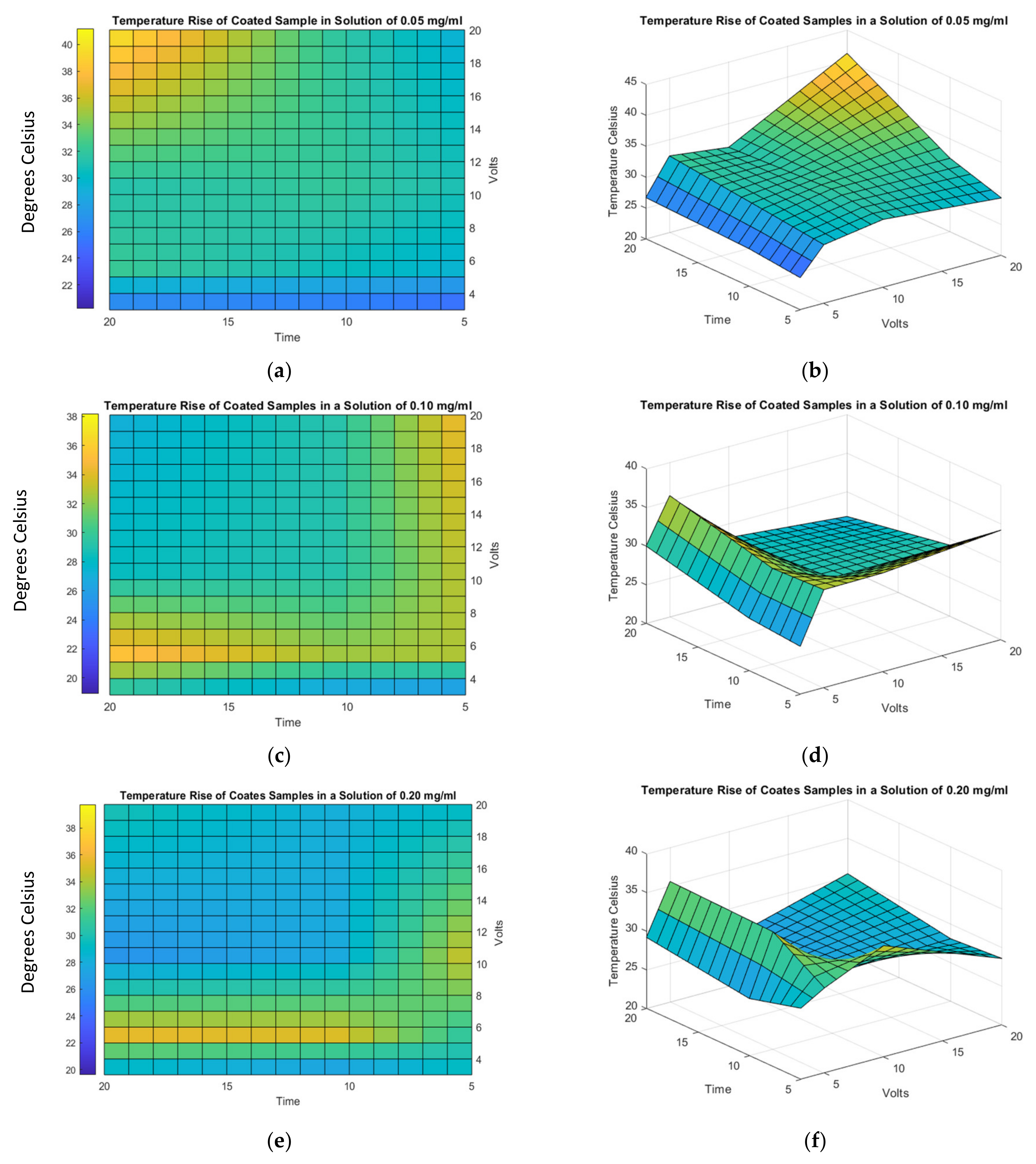
To better understand the influence that the EDP parameters have on the surface thermal dissipation of coated samples, Figure 9 illustrates different curves that show the influence that the concentration of MWCNTs, deposition time and voltage have on the samples’ thermal dissipation performance. Here, the blue regions indicate the process parameter values at which the surface material samples exhibit better thermal dissipation behavior. Figure 9a,b exhibits the coated thermal performance when an MWCNT concentration solution of 0.05 mg/mL is used. Notice that, in this case, the best surface thermal performance is achieved for the lowest applied voltage and for small deposition times. Figure 3b provides evidence that, when low voltage is applied, a broad, well-dispersed film of long highly thermal conductive MWCNTs is deposited. Wang explains this phenomenon, claiming that the high electrical conductivity of the CNTs enhances the material thermodynamic properties [54]. Moreover, notice from Figure 9 that the surface thermal dissipation decreases when longer deposition times and higher concentrations of 0.10 and 0.20 mg/mL MWCNT solution concentration are used, since thicker films and entangled MWCNTs are deposited over the sample surface, hindering the heat exchange between the surface and the coating.
Table 1 exhibits the statistical analysis of the surface thermal dissipation effects of the coated samples versus the MWCNTs concentration values, deposition times and voltages applied. Collected data show that the biggest impact in surface thermal performance is produced by the applied voltage. In fact, low applied voltages produce a well-dispersed and thermally conductive MWCNT deposition. The solution concentration does not produce a big impact on the surface thermal dissipation; even in higher concentrations, only the more conductive MWCNTs are deposited, due to the electrical field applied. The deposition time impacts only for shorter to medium elapsed times, since homogeneous deposited thin film of MWCNTs promotes a higher dissipating area, enabling a larger surface where the heat interchange is produced.

4. Conclusions

This study presented an enhancement to the electrical conductivity and thermal dissipation of aluminum 6061, using MWCNTs through an electrophoresis process. Experimental characterizations based on SEM, XRD, electrical conductivity and thermal dissipation measurements showed that the surface deposition of industrial-grade 95% pure MWCNTs via EPD improves the surface electrical conductivity and thermal dissipation properties.
The main conclusions of the above study may be summarized as follows:
(a)
The best electrical conductivity increment of 9.6% and thermal dissipation reduction of 36% were achieved by considering EDP parameters of 5 and 3 V, respectively, electrodeposition time of 5 min and a concentration solution of 0.05 mg/mL of MWCNTs.
(b)
For longer deposition times and for higher concentration solutions of MWCNT, the electrodeposited carbon nanotubes hinder heat exchange between the surrounding conditions and the coated surface, which reduces thermal dissipation.
Based on the findings of this research, it can be concluded that, when commercial aluminum Al6061 is coated with industrial-grade MWCNTs, its surface electrical conductivity and thermal dissipation reach values like those of materials that are commonly used in electrical applications such as Al1100.
Finally, we would like to point out that adhesion of the deposited carbon nanotubes needs to be investigated in order to have a better understanding of the impact that the deposited film of carbon nanotubes have on the electrical and thermal material properties, since a poor adhesion of the film formed will hinder these properties. Therefore, it is believed that more research work needs to be done to address the adhesion of the deposited carbon nanotubes.
As a final remark, we believe that by controlling the EDP parameter process, as well as the amount and quality of the carbon nanotubes, this coating process can be used for plating metallic surfaces for improving electrical conductivity and thermal conductance of other metallic materials.

Author Contributions

Conceptualization, J.R.-S., M.B.H. and A.E.-Z.; methodology, J.R.-S., M.B.H. and L.G.C.; visualization, A.E.-Z., J.R.-S., M.B.H., N.A.U.-C. and O.M.-R.; formal analysis, A.E.-Z., J.R.-S., M.B.H., N.A.U.-C. and O.M.-R.; investigation, A.E.-Z., J.R.-S., M.B.H., N.A.U.-C., L.G.C. and O.M.-R.; validation, A.E.-Z., J.R.-S., M.B.H., N.A.U.-C., L.G.C. and O.M.-R.; resources, A.E.-Z. and O.M.-R.; data curation, J.R.-S., M.B.H. and L.G.C.; software, M.B.H.; writing—original draft preparation, M.B.H., A.E.-Z. and J.R.-S.; writing—review and editing, A.E.-Z., J.R.-S. and M.B.H.; supervision and project administration, A.E.-Z. and O.M.-R.; funding acquisition, A.E.Z. and O.M.-R. All authors have read and agreed to the published version of the manuscript.

Funding

This research was funded by Tecnológico de Monterrey through the Research Group of Nanotechnology for Devices Design, and by the Consejo Nacional de Ciencia y Tecnología de México (Conacyt), Project Numbers 242269, 255837, 296176, and National Lab in Additive Manufacturing, 3D Digitizing and Computed Tomography (MADiT) LN299129.

Acknowledgments

The authors are thankful to Regina Lizbeth Vargas Mejia for her assistance in the getting SEM images, and to the Mechanical Engineering and Advanced Materials Department for access to Lab. facilities.

Conflicts of Interest

The authors declare no conflict of interest.

References

  1. Bradley, R. Electrical Conductivity-Enhancing and Protection Material. U.S. Patent US4578215A, 25 March 1986. [Google Scholar]
  2. Antonetti, V.W.; Yovanovich, M.M. Enhancement of thermal contact conductance by metallic coatings: Theory and experiment. J. Heat Transfer. 1985, 107, 513–519. [Google Scholar] [CrossRef]
  3. Hill, H.R.T. The Future of Gold and Silver Plating. Trans. IMF 1981, 59, 135–141. [Google Scholar] [CrossRef]
  4. Goodman, P. Current and future uses of gold in electronics. Gold Bull. 2002, 35, 21–26. [Google Scholar] [CrossRef] [Green Version]
  5. Du, C.; Heldbrant, D.; Pan, N. Preparation and preliminary property study of carbon nanotubes films by electrophoretic deposition. Mater. Lett. 2002, 57, 434–438. [Google Scholar] [CrossRef]
  6. Lim, J.; Jalali, M.; Campbell, S.A. Properties of electrophoretically deposited single wall carbon nanotube films. Thin Solid Film. 2015, 589, 278–285. [Google Scholar] [CrossRef]
  7. Castro, R.H.R.; Hidalgo, P.; Diniz, E.C. Enhanced electrical conduction in aluminum wires coated with carbon nanotubes. Mater. Lett. 2011, 65, 271–274. [Google Scholar] [CrossRef]
  8. Che, J.; Cagin, T.; Goddard, W.A. Thermal conductivity of carbon nanotubes. Nanotechnology 2000, 11, 65–69. [Google Scholar] [CrossRef]
  9. Hedges, A.R.; Iijima, S.; Tanaka, K. Carbon Nanotubes and Graphene, 2nd ed.; Elsevier: Amsterdam, The Netherlands, 2014; Volume 98. [Google Scholar]
  10. Dujardin, E.; Ebbesen, T.W.; Hiura, H.; Tanigaki, K. Capillarity and wetting of carbon nanotubes. Science 1994, 265, 1850–1852. [Google Scholar] [CrossRef]
  11. Casati, R.; Vedani, M. Metal matrix composites reinforced by nano-particles—A review. Metals 2014, 4, 65–83. [Google Scholar] [CrossRef]
  12. Bakshi, S.R.; Lahiri, D.; Agarwal, A. Carbon nanotube reinforced metal matrix composites—A review. Int. Mater. Rev. 2010, 55, 41–64. [Google Scholar] [CrossRef]
  13. Silvestre, N. State-of-the-art review on carbon nanotube reinforced metal matrix composites. Int. J. Compos. Mater. 2013, 3, 28–44. [Google Scholar]
  14. Chen, B.; Kondoh, K.; Li, J.S.; Qian, M. Extraordinary reinforcing effect of carbon nanotubes in aluminium matrix composites assisted by in-situ alumina nanoparticles. Compos. Part. B Eng. 2020, 183. [Google Scholar] [CrossRef]
  15. George, R.; Kashyap, K.T.; Rahul, R.; Yamdagni, S. Strengthening in carbon nanotube/aluminum (CNT/Al) composites. Scr. Mater. 2005, 53, 1159–1163. [Google Scholar] [CrossRef]
  16. Vajtai, R. Handbook of Nanomaterials; Springer: Berlin/Heidelberg, Germany, 2012; Volume 108. [Google Scholar]
  17. Mansoor, M.; Shahid, M. Carbon nanotube-reinforced aluminum composite produced by induction melting. J. Appl. Res. Technol. 2016, 14, 215–224. [Google Scholar] [CrossRef] [Green Version]
  18. Esawi, A.; Morsi, K. Dispersion of carbon nanotubes (CNTs) in aluminum powder. Compos. Part. A Appl. Sci. Manuf. 2007, 38, 646–650. [Google Scholar] [CrossRef]
  19. Guo, B.; Chen, Y.; Wang, Z.; Yi, J.; Ni, S.; Du, Y.; Li, W.; Song, M. Enhancement of strength and ductility by interfacial nano-decoration in carbon nanotube/aluminum matrix composites. Carbon 2020, 159, 201–212. [Google Scholar] [CrossRef]
  20. Esawi, A.M.K.; Morsi, K.; Sayed, A.; Gawad, A.A.; Borah, P. Fabrication and properties of dispersed carbon nanotube-aluminum composites. Mater. Sci. Eng. A 2009, 508, 167–173. [Google Scholar] [CrossRef]
  21. Saheb, N.; Iqbal, Z.; Khalil, A.; Hakeem, A.S.; Aqeeli, N.A.; Laoui, T.; Al-Qutub, A.; Kirchner, R. Spark plasma sintering of metals and metal matrix nanocomposites: A review. J. Nanomater. 2012, 2012, 13. [Google Scholar] [CrossRef] [Green Version]
  22. Groza, J.R.; Zavaliangos, A. Sintering activation by external electrical field. Mater. Sci. Eng. A 2000, 287, 171–177. [Google Scholar] [CrossRef]
  23. Uddin, S.M.; Mahmud, T.; Wolf, C.; Glanz, C.; Kolaric, I.; Volkmer, C.; Höller, H.; Wienecke, U.; Roth, S.; Fecht, H. Effect of size and shape of metal particles to improve hardness and electrical properties of carbon nanotube reinforced copper and copper alloy composites. Compos. Sci. Technol. 2010, 70, 2253–2257. [Google Scholar] [CrossRef] [Green Version]
  24. Tokutomi, J.; Uemura, T.; Sugiyama, S.; Shiomi, J.; Yanagimoto, J. Hot extrusion to manufacture the metal matrix composite of carbon nanotube and aluminum with excellent electrical conductivities and mechanical properties. CIRP Ann. Manuf. Technol. 2015, 64, 257–260. [Google Scholar] [CrossRef]
  25. Zhong, R.; Cong, H.; Hou, P. Fabrication of nano-Al based composites reinforced by single-walled carbon nanotubes. Carbon N. Y. 2003, 41, 2001–2004. [Google Scholar] [CrossRef]
  26. Zeng, X.; Zhou, G.; Xu, Q.; Xiong, Y.; Luo, C.; Wu, J. A new technique for dispersion of carbon nanotube in a metal melt. Mater. Sci. Eng. A 2010, 527, 5335–5340. [Google Scholar] [CrossRef]
  27. Kasim, S.H.; Hashim, A.H. Electrophoretic Deposition of multi-walled carbon nanotubes on stainless steel (SS) foils. J. Ind. Technol. 2010, 19, 139–148. [Google Scholar]
  28. Thomas, B.J.C.; Shaffer, M.S.P.; Freeman, S.; Koopman, M.; Chawla, K.K.; Boccaccini, A.R. Electrophoretic deposition of carbon nanotubes on metallic surfaces. Key Eng. Mater. 2006, 314, 141–146. [Google Scholar] [CrossRef]
  29. Merino, C.A.I.; Sillas, J.E.L.; Meza, J.M.; Ramirez, J.M.H. Metal matrix composites reinforced with carbon nanotubes by an alternative technique. J. Alloys Compd. 2017, 707, 257–263. [Google Scholar] [CrossRef]
  30. Thomas, B.J.C.; Boccaccini, A.R.; Shaffer, M.S.P. Multi-walled carbon nanotube coatings using Electrophoretic Deposition (EPD). J. Am. Ceram. Soc. 2005, 88, 980–982. [Google Scholar] [CrossRef]
  31. Sun, Y.; Sun, J.; Liu, M.; Chen, Q. Mechanical strength of carbon nanotube-nickel nanocomposites. Nanotechnology 2007, 18, 505704. [Google Scholar] [CrossRef]
  32. Fraczek-Szczypta, A.; Dlugon, E.; Weselucha-Birczynska, A.; Nocun, M.; Blazewicz, M. Multi walled carbon nanotubes deposited on metal substrate using EPD technique. A spectroscopic study. J. Mol. Struct. 2013, 1040, 238–245. [Google Scholar] [CrossRef]
  33. Ramalingam, S.; Balakrishnan, K.; Shanmugasamy, S.; Subramania, A. Electrodeposition and characterization of Cu–MWCNTs nanocomposite coatings. Surf. Eng. 2017, 33, 369–374. [Google Scholar] [CrossRef]
  34. Selvakumar, A.; Perumalraj, R.; Sudagar, J.; Mohan, S. Nickel multiwalled carbon nanotube composite coating on aluminum alloy rotor for textile industries. J. Mater. Des. Appl. 2016, 230, 319–327. [Google Scholar] [CrossRef]
  35. Madhu, S.; Kumaran, P.; Kumar, A.A.; Raafiq, N.M.; Murali, G. Pulse electro co-deposited Ni/MWCNTS coatings on al 6061 substrate using pulse electroplating. Rasayan J. Chem. 2017, 10, 1472–1480. [Google Scholar]
  36. Xu, C.L.; Wei, B.Q.; Ma, R.Z.; Liang, J.; Ma, X.K.; Wu, D.H. Fabrication of aluminum/carbon nanotube composites and their electrical properties. Carbon N. Y. 1999, 37, 855–858. [Google Scholar] [CrossRef]
  37. Boccaccini, A.R.; Cho, J.; Roether, J.A.; Thomas, B.J.C.; Minay, E.J.; Shaffer, M.S.P. Electrophoretic deposition of carbon nanotubes. Carbon 2006, 44, 3149–3160. [Google Scholar] [CrossRef]
  38. Lee, S.H.; Woo, S.P.; Kakati, N.; Kim, D.J.; Yoon, Y.S. A comprehensive review of nanomaterials developed using electrophoresis process for high-efficiency energy conversion and storage systems. Energies 2018, 11, 3122. [Google Scholar] [CrossRef] [Green Version]
  39. Yatsushiro, T.; Koura, N.; Nakano, S.; Ui, K.; Takeuchi, K. Electrodeposition of aluminum-carbon nanotube composite from room—Temperature molten salt electrolyte. Electrochemistry 2006, 74, 233–236. [Google Scholar] [CrossRef]
  40. Azam, M.A.; Talib, E.; Seman, R.N.A.R. Direct deposition of multi-walled carbon nanotubes onto stainless steel and YEF foils using a simple electrophoretic deposition for electrochemical capacitor electrode. Mater. Res. Express 2019, 6, 015501. [Google Scholar] [CrossRef]
  41. Hekmat, F.; Sohrabi, B.; Rahmanifar, M.S.; Jalali, A. Electrophoretic deposition of multi-walled carbon nanotubes on porous anodic aluminum oxide using ionic liquid as a dispersing agent. Appl. Surf. Sci. 2015, 341, 109–119. [Google Scholar] [CrossRef]
  42. Esumi, K.; Ishigami, M.; Nakajima, A.; Sawada, K.; Honda, H. Chemical treatment of carbon nanotubes. Carbon N. Y. 1996, 34, 279–281. [Google Scholar] [CrossRef]
  43. Arrigo, R.; Teresi, R.; Gambarotti, C.; Parisi, F.; Lazzara, G.; Dintcheva, N.T. Sonication-induced modification of carbon nanotubes: Effect on the rheological and thermo-oxidative behaviour of polymer-based nanocomposites. Materials 2018, 11, 383. [Google Scholar] [CrossRef] [Green Version]
  44. Sarkar, A.; Hah, D. Electrophoretic deposition of carbon nanotubes on silicon substrates. J. Electron. Mater. 2012, 41, 3130–3138. [Google Scholar] [CrossRef]
  45. Lau, K.-T.; Azam, M.A.; Seman, R. Influence of pulsed electrophoretic deposition of graphitic carbon nanotube on electrochemical capacitor performance. J. Eng. Sci. Technol. 2018, 13, 295–308. [Google Scholar]
  46. Kamat, P.; Thomas, K.; Barazzouk, S.; Girishkumar, G.; Vinodgopal, K.; Meisel, D. Self-assembled linear bundles of single wall carbon nanotubes and their alignment and deposition as a film in a dc field. J. Am. Chem. Soc. 2004, 126, 10757–10762. [Google Scholar] [CrossRef] [PubMed]
  47. Basu, R.N.; Randall, C.A.; Mayo, M.J. Fabrication of dense zirconia electrolyte films for tubular solid oxide fuel cells by electrophoretic deposition. J. Am. Ceram. Soc. 2001, 84, 33–40. [Google Scholar] [CrossRef]
  48. Zare, Y.; Yop Rhee, K.; Park, S.J. Modeling the roles of carbon nanotubes and interphase dimensions in the conductivity of nanocomposites. Results Phys. 2019, 15, 102562. [Google Scholar] [CrossRef]
  49. Feng, C.; Jiang, L. Micromechanics modeling of the electrical conductivity of carbon nanotube (CNT)-polymer nanocomposites. Compos. Part. A Appl. Sci. Manuf. 2013, 47, 143–149. [Google Scholar] [CrossRef]
  50. Deng, F.; Zheng, Q.S. An analytical model of effective electrical conductivity of carbon nanotube composites. Appl. Phys. Lett. 2008, 92. [Google Scholar] [CrossRef]
  51. Wang, Y.-C.; Leu, I.-C.; Hon, M.-H. Kinetics of electrophoretic deposition for nanocrystalline zinc oxide coatings. J. Am. Ceram. Soc. 2004, 87, 84–88. [Google Scholar] [CrossRef]
  52. Suryawanshi, C.N.; Lin, C.T. Radiative cooling: Lattice quantization and surface emissivity in thin coatings. ACS Appl. Mater. Interfaces 2009, 1, 1334–1338. [Google Scholar] [CrossRef]
  53. Zhang, G.; Jiang, S.; Zhang, H.; Yao, W.; Liu, C. Excellent heat dissipation properties of the super-aligned carbon nanotube films. RSC Adv. 2016, 6, 61686–61694. [Google Scholar] [CrossRef]
  54. Wang, S.; Liang, R.; Wang, B.; Zhang, C. Dispersion and thermal conductivity of carbon nanotube composites. Carbon 2009, 47, 53–57. [Google Scholar] [CrossRef]
Figure 1. (a) Zeta potential distribution of the multi-walled carbon nanotubes (MWCNTs) solutions used before and after the chemical oxidation. (b) Thermogravimetric analysis (TGA) measurements for MWCNTs and carboxyl-functionalized MWCNTs. The loss of mass for functionalized material under 400 °C indicates the presence of functional groups attached to the MWCNTs during the oxidation process.
Coatings 10 00656 g001
Figure 2. Electrodeposition process of MWCNTs over Al6061. (a) Schematic view of the electrophoresis deposition (EPD), which is carried out by applying a voltage between the cathode (container) and the anode (sample), inducing the motion of the MWCNTs in the suspension to produce a thin film over the sample. (b) Test setup of the array used to perform the EPD over Al6061 material samples. The voltage supplied source was carefully controlled to ensure repeatability over the carry out experiments.
Coatings 10 00656 g002
Figure 3. (a,b) SEM micrographs for Al 6061 substrate used for electrodeposition of MWCNTs. (c,d) Micrographs of the MWCNTs/Al 6061 samples after the electrodeposition process at 3 V during 20 min, using the 0.2 mg/mL solution. Notice some regions in which the MWCNTs tend to agglomerate over the surface of the Al 6061 substrate. Furthermore, these SEM images indicate a varying surface-coating quality depending on the applied EPD parameter values which agree with the results found in Reference [44].
Coatings 10 00656 g003
Figure 4. XRD diffractograms for Al 6061 and electrodeposited specimens MWCNTs/Al 6061. The XRD diffractogram shows the main characteristic reflection planes for aluminum 60161.
Coatings 10 00656 g004
Figure 5. %IACS as a function of the MWCNTs’ concentration solutions. The electrical conductivity is enhanced by 9.6%, 7% and 9.6%, respectively, for MWCNTs concentrations of 0.05, 0.10 and 0.20 mg/mL. The thin films of MWCNTs that electrodeposited over the metallic surface are capable of overcoming the percolation threshold, even for the lowest MWCNT-solution concentration.
Coatings 10 00656 g005
Figure 6. Electrical conductivity (%IACS) measurements performed at different MWCNT concentrations. (a) Top view and (b) schematic view of the %IACS for metallic samples coated in a solution of 0.05 mg/mL of MWCNT. (c) Top view and (d) schematic view of the %IACS for metallic samples coated in a solution of 0.10 mg/mL of MWCNT. (e) Top view and (f) schematic view of the %IACS for metallic samples coated in a solution of 0.20 mg/mL of MWCNT. Experimental results show that electrical conductivity on the surface of the coated Al6061 samples improves them with lower deposition times and applied voltage for small solution concentrations of MWCNT used in EDP. For higher concentration solutions of 0.20 mg/mL of MWCNT, the %IACS increases for higher voltages and prolonged deposition times.
Coatings 10 00656 g006aCoatings 10 00656 g006b
Figure 7. (a) Schematic diagram of the thermal dissipation experiment. (b) The uncoated samples of Al6061 exhibit a temperature rise of 34 °C, while those coated with MWCNTs concentration solutions of 0.05, 0.10 and 0.20 mg/mL exhibit an average maximum temperature rise of 26, 27.66 and 28.6 °C, respectively. These values represent a surface thermal dissipation improvement, respectively, of 31%, 24% and 19%, when compared to the uncoated material aluminum samples.
Coatings 10 00656 g007
Figure 8. Surface thermal dissipation performance as a function of the MWCNTs’ concentration solutions. Thermal dissipation performance improves 31%, 24% and 19% for Al6061 samples coated with MWCNTs concentration solutions of 0.05, 0.10 and 0.20 mg/mL, respectively.
Coatings 10 00656 g008
Figure 9. Surface temperature rise for different MWCNTs concentration solutions. (a) Top view and (b) schematic view of the surface temperature rise for metallic samples coated in a solution of 0.05 mg/mL MWCNT. (c) Top view and (d) schematic view of the surface temperature rise for metallic samples coated in a solution of 0.10 mg/mL MWCNT. (e) Top view and (f) schematic view of the surface temperature rise for metallic samples coated in a solution of 0.20 mg/mL MWCNT. Experimental results show that surface thermal dissipation of the coated Al6061 samples improves linearly for small voltage and short deposition time when low MWCNT concentrations are used. However, for higher MWCNT concentration solutions, the surface thermal dissipation is enhanced when thicker MWCNT layers are deposited over the metallic surface.
Coatings 10 00656 g009
Table 1. Average of the % International Annealed Copper Standard (IACS) and maximum temperature rise obtained after deposition. The electrical conductivity on the surface commercial Al 6061 samples was increased 9.6% by the EDP when the electrodeposition was performed in a solution with a concentration of 0.05 mg/mL of MWCNTs, after the sample was deposited for 5 min and by applying a power voltage of 5 V. Temperature performance was improved by 36% when the sample was coated with MWCNTs concentration solutions of 0.05 mg/mL, applied voltage of 3 V, during 5 min.
MWCNT ConcentrationVoltageEDP Elapsed TimeElectrical ResistivityStandard DeviatonTemperature Rise
(mg/mL)(V)(min)(% IACS) (°C)
0--43.2-34.3
0.05 13 V 15 min 143.580.281525.2
10 min43.580.280726.1
20 min44.030.332726.7
5 V 15 min 147.700.599329.5
10 min44.142.22030.5
20 min43.490.95032.4
10 V5 min44.470.980531.0
10 min42.861.21832.1
20 min44.470.297331.2
20 V5 min40.511.57129.4
10 min41.951.08931.9
20 min44.811.44141.2
0.103 V5 min44.680.360626.2
10 min42.660.729926.8
20 min44.550.305130
5 V5 min43.811.93232.7
10 min43.810.182832.4
20 min46.573.01735.7
10 V5 min44.811.00332.8
10 min46.210.914529.1
20 min43.170.750728.2
20 V5 min43.810.729934.2
10 min44.810.785329.2
20 min44.140.561326.8
0.20 23 V5 min44.160.234629.2
10 min45.320.356427.4
20 min43.140.290729.2
5 V5 min44.470.957031.0
10 min45.500.512335.2
20 min44.811.21935.6
10 V5 min42.550.510134.3
10 min40.251.31327.7
20 min43.810.885726.1
20 V 25 min45.501.18928.6
10 min45.851.96828.1
20 min 247.701.45130.4
1 Lowest range of parameters used in the EDP. 2 Highest ranges of parameters used in the EDP.
Table 2. Surface Roughness Measurement for Al6061 as received versus samples coated with EDP in a solution of 0.05 mg/mL of MWCNTs. Notice surface roughness average values (µm) of the coated samples improve about 16% and 12% for applied voltages 5 and 20 volts, respectively.
Al 6061RaRqRz
0.05 mg/mL MWCNT(µm)(µm)(µm)
00.13350.17050.5847
5 V0.11900.14570.5342
20 V0.12150.1510.5080