Abstract
Si doped diamond-like carbon (Si-DLC) films were deposited on nitrile-butadiene rubber (NBR), and the effects of deposition parameters on the mechanical and tribological properties of an Si-DLC top layer on NBR were investigated. Then, the sample with the best performance is selected to investigate its tribological behaviors and mechanism under different contact loads. The results show that the growth rate and the doped Si content are also decreased with increasing the CH4 flow rate. The Si atom exists in the form of Si-C bonds at low CH4 flow rate (≤40 sccm) and Si-C + Si-O-C bonds at high CH4 flow rate (≥60 sccm). Furthermore, the sp3 content increases monotonously, while the hardness and H3/E2 ratio firstly decreases and then increases. As a result, the friction and wear behaviors are in line with the change trend of the hardness. The lowest friction coefficient (~0.19) and a slight wear were achieved for the Si-DLC3 film under the relatively high load of 3 N. The tribological results indicate that the friction coefficient and wear increase monotonously with the increase of load, which is mainly attributed to the brittle fragmentation of films at a higher load, and thus a high strength and super toughness DLC films should be needed. Furthermore, the friction and wear behaviors of samples depend critically on its surface topography, and the wear is lower when the friction direction is parallel to the stripes.
1. Introduction
Nitrile-butadiene rubber (NBR) seals are subject to high friction and wear due to its adhesion-prone to the harder counterpart (ceramic, steel, etc.) at a relatively high load, which lead to the loss of its function and failure of the sealing system. Considering that the friction and wear always occur on the surface and subsurface of materials, and thus the surface coatings with excellent friction and wear have been suggested as protective coatings. Diamond-like carbon (DLC) film is popularly regarded as a promising protective coating because of their outstanding mechanical and tribological properties such as high hardness, low friction coefficient and high wear resistance [1,2,3,4,5,6]. In the past decade, the related studies experienced great momentum since T. Nakahigashi et al. [7] claimed that a new flexible film has been applied to the rubber o-rings for zoom cameras. Among, many exploratory works have been done by Japanese scholars [8,9,10,11,12], J. Th. M. De Hosson’s group [13,14,15,16,17] and M. Lubwama’s group [18,19,20,21]. These results show that DLC based films can significantly improve the tribological properties of NBR.
As is known, incorporation of other elements (such as metal elements like W [22], Cu [23], etc. and non-metal elements like Si [24], N [25], etc.) into the DLC films provides an effective way for reducing the friction and wear. Among these doping elements, silicon is one of the most promising candidates. Fujimoto et al. [26] found the hardness and friction coefficient increases with increasing tetramethylsilane flow ratio (or Si content). Zhang et al. [27] reported that the hardness of Si doped diamond-like carbon (Si-DLC) film initially increases and then decreases, while its wear rate firstly decreases and then increases with the increase of Si content. However, Jiang [28] et al. observed the opposite results from Zhang’s research [27]. Clearly, there is no agreement on the effect of Si content (or deposition parameters) on the properties of the films. Moreover, the above-mentioned research works are based on coatings applied to either silicon wafer or various metallic substrates, while the effects of deposition parameters of Si-DLC top layer on its microstructure, mechanical and tribological properties on NBR rubbers still not well investigated.
With the exception of the mentioned above, these research works have been made with an emphasis on the hardness, hydrocarbon precursors or doping materials, and the tribological performance of DLC coated NBR was not well explored. Just like other carbon materials, the tribological behaviors of DLC films are strongly sensitive to the test conditions, especially the friction loads. Generally, the friction coefficient decreases as increasing the friction load for DLC films on hard substrate. So far, various theories have been proposed to explain this phenomenon as follows: (1) Hertzian elastic contact theory. It is mainly used to explain the influence of friction load on the tribological behavior, and the friction coefficient decrease as increasing contact pressure [29,30,31]; (2) Graphitization. This classic theory holds that the friction thermal effect will lead to the transformation of sp3 to sp2, i.e., form the graphitized tribo-layer on the coating surface [32,33]; and (3) Transfer film. The graphitized wear debris could gradually transfer to the counterpart surface and form an easy-to-shear transfer film [34,35,36]. The occurrence of graphitization and the formation of a transferred tribo-film are considered to play the significant role in achieving low friction in DLC films under a high load. Unlike hard substrates, however, the viscoelasticity of soft substrates can lead to a significant change in the contact state, and thus the tribological behavior of DLC films on soft substrates must be different from that on hard substrates.
In this work, Si interlayer/Si-DLC top layers were deposited successfully on NBR, and the objective is to investigate the effects of CH4 flow rate on the microstructure, mechanical, and tribological properties of an Si-DLC top layer on NBR in order to obtain an optimal sample, and then its tribological behaviors and mechanism have also been studied under different contact loads. The principal purpose of this study is to deposit DLC-based films with excellent wear resistance on NBR by selecting a suitable CH4 flow rate (or Si contents), and to further explore the tribological mechanism of DLC-based films coated under different loads for a wide range of tribological application under harsh conditions.
2. Materials and Methods
2.1. Film Deposition
Si-DLC films were prepared on NBR by magnetron sputtering Si target (99.99% purity) using Ar and CH4 as the precursor gas. Black NBR sheets with the thickness of 2 mm was firstly cut into 20 × 20 mm2 and adopted as substrates, its surface roughness is about 1 µm. All NBR substrates were ultrasonically pre-cleaned with soapy water and then hot deionized water in order to remove the contaminations. Prior to the deposition, the chamber was evacuated up to 1.0 × 10⁻³ Pa, and all NBR substrates were pretreated by an argon discharge for 15 min. The films deposition followed immediately after Ar plasma pre-treatment, and Si layer was firstly deposited on NBR as an interlayer. During the Si-DLC top layers deposition, the flow rate of Ar maintained a constant value of 50 sccm, while the CH4 flow rate was changed from 20 to 150 sccm. The power of the sputtering source was about 0.46~0.50 kW, the working pressure was about 1.0 Pa, the negative pulsed bias voltage was −700 V, the deposition time was kept at 35 min for all the samples, and the NBR substrates were clamped 100 mm apart from the Si targets. Moreover, the sample holder always stays in front of the Si target and rotates itself at the speed of 5 r/min during the whole deposition.
2.2. Sample Characterization
The surface and cross sectional morphology of coated NBR were characterized with scanning electron microscope (LYRA3 TESCAN, ThermoScientific™ Apreo S, SEM, Thermo Scientific, Waltham, MA, USA). The microstructure characterization was performed via high-resolution transmission electron microscopy (HRTEM) using a Tecnai F30 TEM operated at accelerating voltage of 300 kV, the Si-DLC layer (~30 nm) were first grown on NaCl wafer, and then the NaCl wafer was dissolved into the distilled water followed by placing the film onto Cu grids. The chemical composition of the films was determined by an ESCALAB 250Xi type X-ray photoelectron spectroscopy (XPS, ThermoFisher Scientific, USA) under high vacuum (<10−9 mbar), with a monochromatic Al Kα radiation (hν = 1486.6 eV) as the excitation source. Further investigation of the chemical bonding of the films was examined by using a LabRAM HR Evolution Raman Spectroscope (HORIBA Jobin Yvon S.A.S., France) at the excitation wavelength of the 532 nm. The mechanical properties of films on Si wafer were measured by nanoindentor (Hysitron TI-950 triboindenter, USA), the indentation depth is about 1/10 of the film thickness, and the maximum load applied is ~150 µN.
The tribological performance was conducted at room temperature (23 °C) on self-developed friction and wear tester with a rotating ball-on-disc configuration selecting a commercial ø6 mm GCr15 steel balls as counterparts. The parameters of tribotests were as followings: the frictional load was 3 N, and the rotational speed was fixed to 300 rpm with a radius of 4 mm. The testing time was 60 min, a constant humidity is 27 ± 1% kept with a humidity regulator. After testing, the surface morphology and chemical composition of wear tracks (or wear scar on counterparts) of Si-DLC coated NBR was characterized with SEM and EDS (Energy Dispersive Spectrometer) analysis. In the further text, sometimes the terms “Si-DLC1, Si-DLC2, Si-DLC3, Si-DLC4, and Si-DLC5” were used to denote the Si-DLC top layers deposited at different CH4 flow rate of 20, 40, 60, 100, and 150 sccm, respectively.
Based on this work, a large number of Si-DLC3 samples have been prepared to analyze the friction mechanism of films under different loads and speeds. The applied normal loads were selected to be 1, 4, 7, and 10 N, the rotational speed was fixed to 300 rpm with a radius of 4 mm, and the testing time is 60 min. All the tribotests were carried out at least three times to ensure the repeatability. At the same time, the friction and wear properties of uncoated NBR under the different loads were also investigated as a comparison. After testing, the surface morphology of wear tracks of Si-DLC coated NBR was characterized with SEM and optical microscope, and the chemical bonding of wear tracks was measured by using a Raman Spectroscope. In the further text, the terms “DLC-1 N, DLC-4 N, DLC-7 N, and DLC-10 N” were used to denote the coated NBR, while the terms “xj-1 N, xj-4 N, xj-7 N, and xj-10 N” were used to denote the uncoated NBR with a friction load of 1, 4, 7, and 10 N.
3. Results and Discussion
3.1. Surface and Cross-Sectional Morphology
Figure 1 displays the overview of the surface morphology of the Si-DLC films deposited at the different CH4 flow rate on NBRs. As can be seen, a lot of regular stripes resulting from the rolling process can be found on coated NBR. At the same time, some random cracks, which are almost perpendicular to these stripes, are always observed on films because of the huge difference in temperature during and after the film deposition, while the existence of these cracks has a positive effect on improving the flexibility and internal stress of DLC or DLC-based films on rubbers [21]. Furthermore, it should be mentioned that the crack density of films deposited at low CH4 flow (Figure 1a,b) is higher than that deposited at high CH4 flow (Figure 1c,d). D. Martinez-Martinez et al. [37] found that the crack density is directly related to the temperature difference (ΔT) from the beginning to the end of deposition, and the larger the temperature difference (|ΔT|) means the larger the crack density. This result indicates that the temperature difference of the films deposited at high CH4 flow rates is relatively smaller than that deposited at low CH4 flow rates, and the reasons will be discussed in more detail in the following.
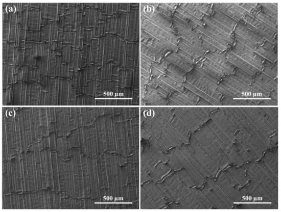
Figure 1.
Scanning electron microscope (SEM) images of surface morphology of the Si doped diamond-like carbon (Si-DLC) films deposited at different CH4 flow rates of: (a) 20 sccm, (b) 40 sccm, (c) 100 sccm, and (d) 150 sccm on nitrile-butadiene rubber (NBR).
Figure 2 presents the fractured cross sections of Si-DLC films deposited at the different CH4 flow rate on NBR. It can be seen that all Si interlayers exhibit the typical columnar structure, and its thickness maintains a constant value of 1.20 ± 0.07 µm. However, all Si-DLC top layers exhibit a very dense, columnar-free structure due to the higher ion energy (or substrate bias) during the film deposition. Also, the thickness of Si-DLC top layers is significantly different at the different CH4 flow rate. It can be observed that the thickness of Si-DLC top layers is 0.70 ± 0.05 µm for Si-DLC1 film, as CH4 flow rate increases, the thickness is obviously decreased to 0.56 ± 0.07 µm for the Si-DLC2 film. As CH4 flow rate increases further to 60 sccm, the Si-DLC layer thickness is markedly decreased to 0.25 ± 0.02 µm for the Si-DLC3 film. Hereafter, the Si-DLC layer thickness has hardly changed (0.21 ± 0.02 µm for the Si-DLC4 film and 0.21 ± 0.03 µm for the Si-DLC5 film) as the increase of CH4 flow rate from 60 to 150 sccm. The thickness (growth rate) of the films is usually closely related to the deposition process, and the analysis of the deposition process can reasonably explain the above-mentioned phenomena.
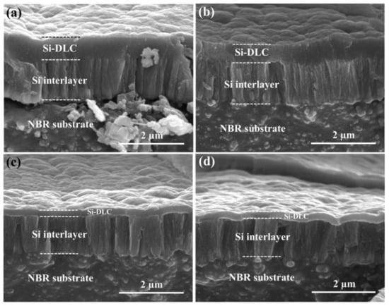
Figure 2.
The fractured cross section of Si-DLC films deposited at different CH4 flow rates of: (a) 20 sccm, (b) 40 sccm, (c) 100 sccm, and (d) 150 sccm on NBR.
During the deposition, the CH4 was used as the C source and the Si target was used as the Si source, while CH4 could be ionized into ionic hydrocarbon radicals (CH+ and CH3+) and ionic hydrogen (H and H+) and so on. At relatively low CH4 flow rate, the ionization rate of CH4 gas is relatively high because of the collision of large amount of Ar+ ion and the CH4 gas, which causes the high growth rate of films. Meanwhile, a large number of ions bombarding the substrate results in an increase in its surface temperature. As the CH4 flow rate increases, the silicon target is partially covered by these ionized species, which leads to the low ionic bombardment energy (low substrate temperature) and the corresponding low deposition rate. As the CH4 flow ratio increases further, Si target has been almost completely covered by carbon species from ionized CH4 gas (so-called “target poisoning”). At this moment, Si atoms are hardly sputtered out from the Si target surface, and the ionization rate of CH4 gas and the ionic energy are the lowest because of the lack of strong sputter yield. As a consequence, the deposition rate, substrate temperature and Si content are quite low and remains almost constant values. This may be the main reason for the decrease of deposition rate, crack density and Si content (see XPS analysis) with the increase of CH4 flow rate.
3.2. Chemical Composition and Microstructure Analysis
The HRTEM image and the corresponding SAED (Selected-area electron diffraction) pattern of the Si-DLC films deposited at different CH4 flow rates on NBR are shown in Figure 3. As can be found that when the CH4 flow rate is relatively low (20 sccm), some special structures (marked by dashed line area) can be observed in the film (Figure 3a). The phases are identified through lattice spacing and the corresponding SAED patterns as shown in Figure 3a insert, it is clear that the lattice spacing between adjacent stripes is found to be about 2.1 Å and the SAED pattern displays a diffraction ring (corresponding to (200) face of β-SiC phase), which clearly reveals that the Si-DLC top layer has a typical nanocomposite structure that consists of nanocrystals and amorphous phases. However, as the CH4 flow rate increases to 60 sccm, no special structure (like nanocrystals) is observed in the film, the corresponding SAED also displays a diffuse halo without any diffraction ring. As the CH4 flow rate increases finally to 150 sccm, the films show the same amorphous characteristics. In order to further analyze the composition and the existence form of incorporated Si in the films, XPS was used as a reliable and efficient tool.
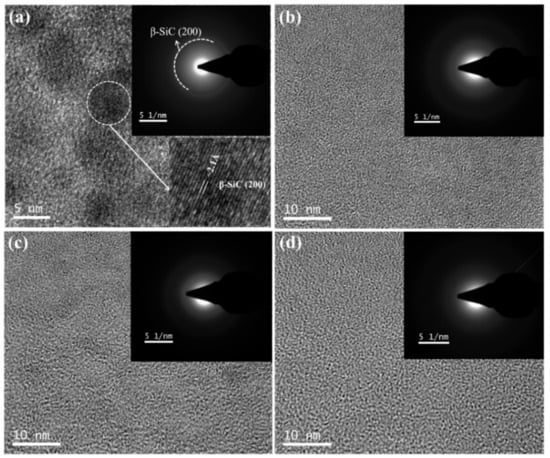
Figure 3.
High-resolution transmission electron microscopy (HRTEM) images and the corresponding SAED patterns of the Si-DLC films deposited at different CH4 flow rates of: (a) 20 sccm, (b) 60 sccm, (c) 100 sccm, and (d) 150 sccm on NBR.
Figure 4a shows the typical XPS survey spectra of the Si-DLC films deposited at different CH4 flow rates. There are clearly visible main peaks of C1s at ~284 eV, O1s at ~531 eV, Si2p at ~101 eV and Si2s at ~150 eV. This result has clarified that the film composes mainly of carbon, silicon, and oxygen. The existence of oxygen may be associated with the residual moisture in the chamber or the air exposure of samples during its storage. The chemical composition of the films as a function of CH4 flow rates is presented in Figure 4b. As can be seen, the C content almost linearly increases from 77.87 to 95.30 at.% with the increase of CH4 flow rate from 20 to 150 sccm, while the Si concentration monotonously decreases from 9.88 to 0.30 at.%. The content of O atoms presents the same trend as that of Si atoms and decreases from 12.25 to 4.40 at.%. Moreover, it is worth mentioning that the Si content is quite low (0.30 at.%) due to the critical “target poisoning” effect at the high CH4 flow rate (150 sccm), and thus this film (Si-DLC5 film) can be considered as a pure DLC film in this work.
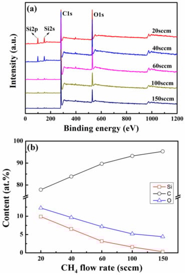
Figure 4.
(a) The typical X-ray photoelectron spectroscopy (XPS) survey spectra and (b) chemical composition of the Si-DLC films deposited at different CH4 flow rates.
Figure 5a displays the XPS C1s spectra of the Si-DLC films deposited at different CH4 flow rate on NBR substrate. A major peak at ~284.0 eV is found for all samples, and this C1s peak shifts towards higher binding energy as the CH4 flow rate increases from 20 to 150 sccm, which implies the increased sp3-C bonds content. In order to obtain more accurate data, the C1s spectra were deconvoluted into four different Gaussian peaks located at ~283.8 eV for Si-C bonds [38], ~284.5 eV for sp2-C bonds, 285.3 eV for sp3-C bonds, and 287.5 eV for C=O bonds, respectively. Subsequently, the sp3/sp2 ratio can be obtained by taking the ratio of the sp3 peak area over the sp2 peak area as shown in Figure 5b. It is clear that the sp3/sp2 ratio increases monotonically from 0.17 to 0.58 as the increase of the CH4 flow rate from 20 sccm to 150 sccm, which implies an increase in sp3 content. To further explore the binding form of Si in DLC matrix, it is necessary to analyze the Si2p peak. Figure 6 shows the Si2p peak of films as a function of CH4 flow rate. It can be found that the Si2p peak is located at lower binding energy at low CH4 flow rate, as the CH4 flow rate increases, the Si2p peak shifts towards the higher energy (Figure 6a), which indicates the change of the binding form of Si atoms in the films. From Figure 6b–f, it can be observed that the Si2p peak could only be fitted into one peak at ~100.3 eV at low CH4 flow rate (≤40 sccm), corresponding to the Si-C bonds [39], which implies that the incorporated Si probably exists in the form of Si-C bonds at low CH4 flow rate, in consistent with the TEM observation. As the CH4 flow rate increases further, however, the Si2p peak could be fitted into two peaks at ~100.3 eV for Si-C bonds and ~101.3 eV for SiOxCy bonds [40], which indicates that the incorporated Si probably exists in the form of SiC and SiOxCy at relatively high CH4 flow rates (≥60 sccm).
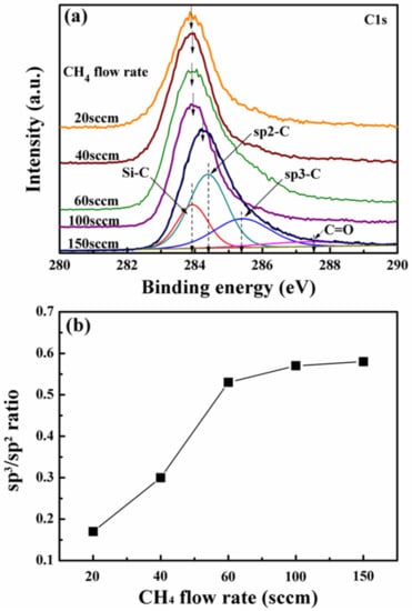
Figure 5.
XPS C1s spectra (a) and the sp3/sp2 ratio (b) of the Si-DLC films deposited at different CH4 flow rate on NBR.
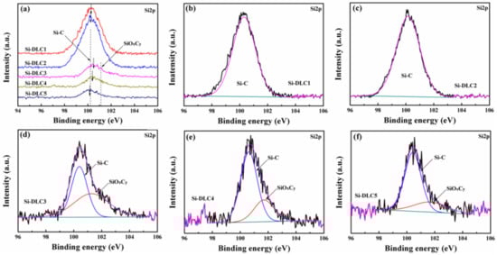
Figure 6.
(a) the Si2p spectra of the Si-DLC films deposited at different CH4 flow rate on NBR, and the fitted Si2p spectrum of (b) Si-DLC1 film, (c) Si-DLC2 film, (d) Si-DLC3 film, (e) Si-DLC4 film and (f) Si-DLC5 film.
The XPS is a very effective way to obtain the film’s composition, but it is hardly applied to a very tiny area, while Raman spectroscopy was used to measure the detailed structural characterization of the Si-DLC film. Figure 7a displays the fitted Raman spectra of the Si-DLC films deposited at different CH4 flow rate on NBR, which mainly consists of two peaks located at around 1550 cm−1 (G peak) and 1350 cm−1 (D peak) for all films. Normally, the G peak position and the intensity ratio of the D peak to G peak (ID/IG) can provide important information about the sp3 content, and the G peak position and ID/IG ratio are shown in Figure 7b. It is clearly found that the ID/IG ratio decreases from 1.03 to 0.58 and the G peak position shifts from 1597 to 1569 cm−1 as the increase of CH4 flow rate from 20 sccm to 150 sccm. This result indicates the increase in sp3 content in films, which is well consistent with the XPS analysis. The increased sp3 content could be explained as followings: the CH4 could be decomposed into a large amount of ionic hydrogen (H, H+) as above mentioned in Section 3.1, and an increase in CH4 flow ratio leads to an increase in dissociated hydrogen content in the films, which promotes the formation of sp3-CH by saturating the C=C bonds.
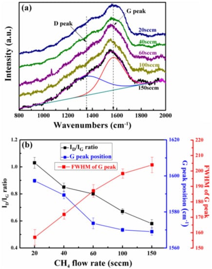
Figure 7.
(a) Raman spectra and (b) ID/IG ratio, FWHM (full width half maximum) of G-peak and G position of the films deposited at different CH4 flow rate on NBR.
FWHM (full width half maximum) of G peak is an important parameter closely related to the residual stress, because it is mainly sensitive to the degree of the structure disorder resulting from bond angle and bond length disorders. M. Lubwama et al. [18] found that the smaller FWHM of G peak means not only the larger and less strained sp2 clusters, but also the decreased bond length and bond angle disorder, which leads to a decrease in the residual stress. As shown in Figure 7b, the FWHM of G peak increases monotonically from 157 to 204 cm−1 as the increase of the CH4 flow rate from 20 sccm to 150 sccm, which indicates the stress is increased as the increase of the CH4 flow rate. In other words, the residual stress of DLC films can be significantly reduced by Si doping, because longer bond length of Si-C (1.89 Å) (compared to bond length of C–C (1.54 Å)) in the films can relieve stress in a longer-range order [41].
3.3. Mechanical Properties
The precise measurements of hardness (H) and elastic modulus (E) of films on NBR is very difficult because of the elastic deformation of NBR substrate, and thus the corresponding value is evaluated by preparing the same films on Si wafer substrate as a reference. Although the hardness of films on NBR is different from that on Si substrate, the change trend is expected to be the same [42]. Figure 8a depicts the results of the H and E measurements of films deposited at different CH4 flow rate on Si wafer. It can be observed that the H value is relatively high (16.24 GPa) for the Si-DLC1 film. With increasing the CH4 flow rate, the H is sharply decreased to 8.01 GPa for the Si-DLC3 film. However, with increasing the CH4 flow rate further, the H value is slightly increased to 10.58 GPa for the Si-DLC5 film. The trend in the E value is consistent with the H value, and the minimum E value of ~32 GPa is obtained at the CH4 flow rate of 60 sccm. Generally, the sp3 content has considerable influences on the hardness of films, and higher sp3 content resulted in higher hardness [43]. However, in this work, the sp3 content is monotonously increased with increasing CH4 flow rate by XPS and Raman analysis, while the hardness is firstly decreased and then slightly increased, which implies that the sp3 content cannot be used to explain the change of hardness in this work. As a matter of fact, initial decrease in hardness should be attributed to the decreases in the Si-C bonds due to the decrease of Si content, because hard SiC nanoparticles doping into DLC matrix plays a dominant role in the solid solution hardening effect [44]. Moreover, a slight increase in hardness with the increase of CH4 flow rate from 60 to 150 sccm is also ascribed to the formation of Si-C bonds, because the Si-C formation can hinder the continuity of carbon network, and thus resulting in the decrease of hardness. Namely, as the CH4 flow rate increases further, the Si-C bonds decreases due to the decrease of Si content. As a result, the hardness exhibits a slight increase.
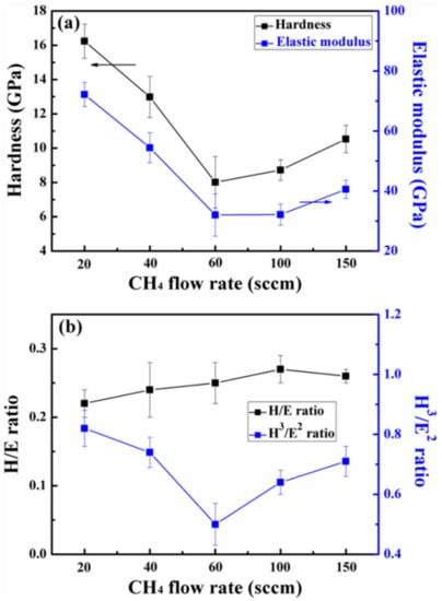
Figure 8.
(a) Hardness, elastic modulus and (b) ratio of hardness and elastic modulus (H/E and H3/E2) of the films deposited at different CH4 flow rate on Si wafer.
Based on the classical wear theories, many researchers have introduced the ratio of hardness and elastic modulus (H/E and H3/E2) to forecast the wear resistance of materials, because H/E ratio is connected with elastic deformation resulting in coatings destruction, it correlates with the ability of the coating to withstand loads. While, H3/E2 ratio is known as the strong indicator of the coating’s resistance to plastic deformation, higher H3/E2 value means higher load-bearing capacity [45]. Figure 8b gives the values of the H/E and H3/E2 ratio obtained for as-deposited films. It is observed that the H/E ratio exhibits a slight increase in range of 0.22~0.27, while the H3/E2 ratio is the highest (0.82) at 20 sccm CH4 flow rate. As the CH4 flow rate increases, the H3/E2 ratio initially decreases and then increases. Clearly, the Si-DLC1 film and Si-DLC5 film should possess a relatively high wear resistance over all other films. Furthermore, it should be noted that the H3/E2 value is an important parameter for the films on NBR, because our previous studies showed that brittle fracture is one of the main reasons of wear failure of DLC-based film on rubber under a higher load, while the H3/E2 value reflects the load-carrying capacity of the films. That is, the higher the H3/E2 value means the stronger the load-carrying capacity and thus better the wear-resistant of the film under the higher load.
3.4. Tribological Properties of Films with Different Si Contents
Figure 9 reveals the friction coefficient curves of the films deposited at different CH4 flow rate on NBR under the friction load of 3 N. The Si-DLC1 film exhibits a relatively high friction coefficient of ~0.24. As increasing the CH4 flow rate to 60 sccm, the Si-DLC3 film presents the lowest and relatively stable friction coefficient of 0.19 than that of other films. As the CH4 flow rate increases further, however, the friction coefficient of the Si-DLC4 film exhibits a dramatically increase (0.21). As the CH4 flow rate increases finally to 150 sccm, the Si-DLC5 film displays an obviously higher friction coefficient (~0.24) than that of the Si-DLC4 film. Figure 10a–d presents the SEM micrographs of the wear tracks of coated NBR with different CH4 flow rate. For the Si-DLC1 film, an obvious wear track (Figure 10a insert) could be observed, the “hill” of the sample stripe is slightly polished, and a small amount of wear debris can be found (Figure 10a) on the wear tracks. As the CH4 flow rate increases to 60 sccm, a slight wear occurs in the “hill” of the stripes, and it is difficult to observe the wear track (Figure 10b insert) and wear debris on the wear track (Figure 10b), meaning the excellent wear resistance for the Si-DLC3 film. As the CH4 flow rate increases further to 100 and 150 sccm, however, a large number of wear debris can be observed (Figure 10c) on the wear tracks of the Si-DLC4 film and its wear track becomes more clearer (Figure 10c insert). Meanwhile, the “hill” of the stripe of the Si-DLC5 film is seriously smoothed (Figure 10d), implying a higher wear rate.
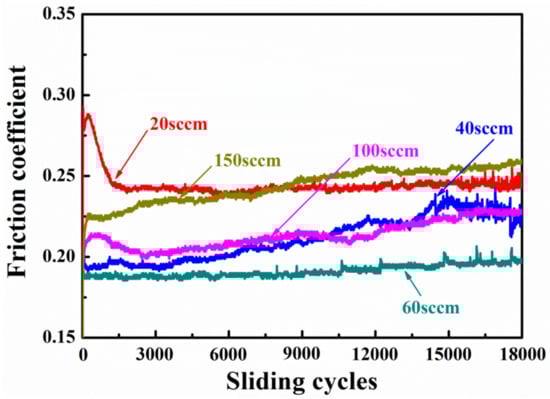
Figure 9.
Friction coefficient of films deposited at the different CH4 flow rate on NBR under the load of 3 N.
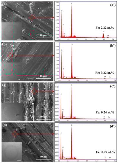
Figure 10.
SEM images of the wear tracks of the Si-DLC films deposited at the different CH4 flow rate of (a) 20 sccm, (b) 60 sccm, (c) 100 sccm, and (d) 150 sccm on NBR, and the corresponding EDS analysis (a’–d’) of the wear tracks.
Theoretically, the Si-DLC1 and Si-DLC5 film should possess a relatively excellent wear resistance due to their relatively high toughness (or H3/E2 ratio, confirmed by the H3/E2 value), but these is no obvious brittle fracture for all films. Moreover, no significant difference in adhesion could also be observed for all the films, and the films do not peel off from NBR substrate during the friction, which indicates that the toughness and adhesion of the films are not the main factors affecting the friction and wear of the films in here.
In order to investigate the difference of friction and wear behavior of samples, it is necessary to analyze the wear track of films and the surface morphology of the corresponding counterpart steel balls, because it can provide effectively an indirect or direct evidence for revealing the friction and wear mechanism. Figure 10a’–d’ illustrates the EDAX analysis of wear tracks of the films deposited at different CH4 flow rate. Interestingly, the Fe atoms could always be observed for all wear tracks, but the Fe content is quite different. As shown in Figure 10a’, the Fe content is relatively high (2.22 at.%) for the Si-DLC1 film, as the CH4 flow rate increases to 60 sccm, the Fe content sharply decreases to 0.22 at.% for the Si-DLC3 film. As the CH4 flow rate increases further to 150 sccm, however, the Fe content exhibits a slight increase (0.29 at.%). Clearly, the observed Fe atom comes from the counterpart steel ball, while the change trend of its content is in line with the trend in the hardness of the films. Furthermore, similar information can also be confirmed by observing the surface topography of counterpart balls. Figure 11 shows the wear scar of the counterpart balls sliding against the coated NBRs. It can be seen that there are many deep scratches formed on the wear scar of the ball when sliding against the Si-DLC1 film (Figure 11a). On the contrary, the wear scar of the counterparts sliding against other samples is smoother and no obvious scratches are observed (Figure 11b–d). Namely, the counterpart sliding against a harder film (Si-DLC1) displays a rougher wear scar, while the one sliding against the softer films (Si-DLC3~Si-DLC5) exhibits the smoother wear scar. It is easy to understand that serious grooves could be observed on the softer counterpart steel ball when sliding against a hard DLC film, at this moment, the contact state of the friction interface changes dramatically from surface-to-surface contact to point-to-surface (or line-to-surface) contact from a microscopic point of view. During the friction, the friction stress can concentrate at these points or lines, which leads to the brittle fracture of the film under the repeated friction load, while these fragmentations or debris in turn aggravate the friction and wear of the film as mentioned earlier. At the same time, the hard film exhibits a serious adhesive friction with the softer counterpart steel, resulting in a high friction coefficient. Moreover, it is worth mentioning that an appropriate hardness is very important for DLC or DLC-based film on NBR, because high hardness can lead to severe wear of its counterpart, and then resulting in the leakage of sealing medium from these wear parts, which is undesirable in practical applications.
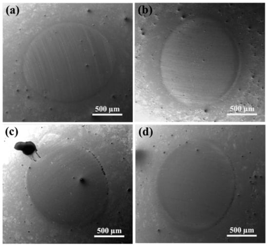
Figure 11.
SEM images of the wear scar of GCr15 balls sliding against the Si-DLC films deposited at different CH4 flow rate of: (a) 20 sccm, (b) 60 sccm, (c) 100 sccm, and (d) 150 sccm on NBR.
3.5. Friction and Wear Behaviors of Si-DLC3 Films under the Different Load
Figure 12 shows the friction coefficient curves of uncoated NBR and Si-DLC coated NBR as a function of the different applied loads (1, 4, 7, and 10 N) in air. For the uncoated NBR, it is clear that it exhibits an opposite relation between the friction coefficient and the applied load that the lower the load is, the higher the friction coefficient is. To deeply investigate this phenomenon, typical wear track morphology of uncoated NBR were observed by SEM and the results were presented in Figure 13. At a low load (1 N), the wear track is narrow and the NBR is slightly worn by a larger magnification observation. With the increase of load (3 N), the width of wear track increases obviously and the “liquid-like” material can be observed on the wear track. As the load increases further to 10 N, the width of wear track becomes wider, and the “liquid-like” material can be clearly observed at a lower magnification observation. For the uncoated NBR, it is generally known that it is a bad conductor of heat and friction heat is not easy to discharge during the friction. At a higher load (>3 N), the occurrence of local melting could be observed because of the accumulation of friction heat, which leads to the change of friction contact state from solid-solid contact to solid-liquid contact, that is, the rubber surface is easier to shear than the bulk, which is the main reason why the friction coefficient of rubber decreases monotonously with the increase of load. However, the “liquid-like” material is more likely to wear, resulting in a monotonously increase in wear rate with the increase of load.
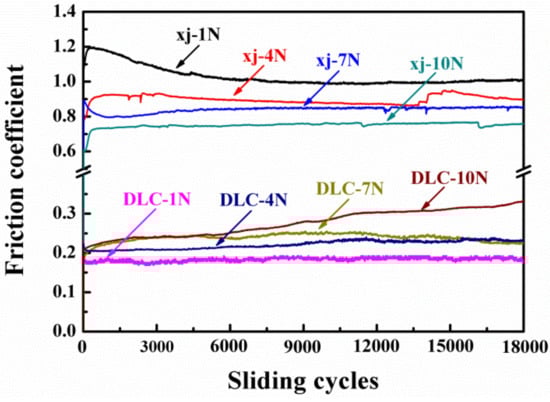
Figure 12.
Friction coefficient curves of uncoated NBR and Si-DLC coated NBR in ambient air as a function of the different applied load.
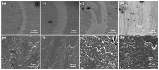
Figure 13.
SEM images of wear track of the virgin NBR rubber under the load of (a,e) 1 N, (b,f) 4 N, (c,g) 7 N, and (d,h) 10 N.
For the coated NBR, the corresponding tribological behaviors are just opposite to that of uncoated NBR. It is obvious that the friction coefficient of all samples is drastically reduced (3~4 times lower), it can be mainly attributed to the chemical inertness of DLC, which weakens the interfacial adhesion between the NBR and the counterpart, but the average friction coefficient of the sample shows different results under the different load. The sample exhibits the lowest friction coefficient (~0.18) and its friction coefficient shows a slight fluctuation at the load of 1 N. As the load increases to 7 N, the friction coefficient increases monotonously to a higher value of 0.23. As the load increases further to 10 N, its friction coefficient increases from the initial value of about 0.2 at the beginning of sliding to the value of 0.32 at the end of the test, the average friction coefficient reaches the highest value of 0.27.
In order to observe its wear behaviors, SEM micrographs of the wear tracks of coated NBR rubbers with the different load are shown in Figure 14. As can be seen, a narrow wear track and a slight worn (Figure 14a insert) could be observed, the wear occurs mainly on the “hill” of the sample stripes at a low load (1 N), a small amount of debris is found at the “valley” of the sample stripe, and no fracture occurred in the films whatever the friction direction is parallel to the stripes or perpendicular to the stripes (Figure 14a,e). As the load increases from 1 to 4 N, the width of wear tracks widens obviously and is up to 1.67 mm (Figure 14b insert), the “hill” site is obviously smoothed and there is a small amount of fractures in the film when the friction direction is perpendicular to the stripes (Figure 14f). As the load further increases from 4 to 7 N, the “hill” and “valley” site are seriously smoothed and the film suffers a serious wear. Meanwhile, a slight fracture could be found when the friction direction is parallel to the stripes (Figure 14c), while a serious fracture could be observed when the friction direction is perpendicular to the stripes (Figure 14g). As the load increases finally to 10 N, the width of wear tracks reaches to 2.2 mm, and a large amount of debris is located on two sides of wear track (Figure 14d insert), while the film were seriously fractured whatever the friction direction is parallel or perpendicular to the stripes.
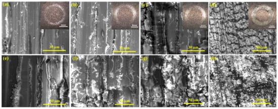
Figure 14.
Microscopic SEM images of wear track of DLC film coated NBR at the different load of (a,e) 1 N, (b,f) 4 N, (c,g) 7 N, and (d,h) 10 N. (a–d) indicates that the friction direction is parallel to the sample fringe direction, while (e–h) indicates that the friction direction is perpendicular to the sample fringe direction.
From the analysis of the above experimental results, it can be speculated that the friction and wear behaviors of the samples are closely related to the fracture degree of the films under the different loads. Therefore, an additional experiment is intentionally designed. That is, the friction and wear behaviors of the film crushed by artificially applying an extra pressure are investigated as a comparison. Figure 15 presents the friction coefficient curves and the corresponding wear behaviors of the crushed film and the original sample under the load of 1 and 10 N. It is evident that the friction coefficient and wear rate of the crushed film are significantly higher than that of the original sample at a low or high load. Based on the above analysis, the mechanism of friction and wear of the coated NBR under the different loads will be discussed in the following.
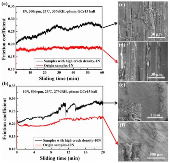
Figure 15.
(a,b) The friction coefficient curves and SEM images of wear track of the crushed films (c,e) and the original samples (d,f) under the load of 1 N and 10 N.
From the above analysis, it can be safely concluded that the friction coefficient and wear rate of DLC-coated NBR increase monotonously with the increase of friction load, as opposite to what is expected in conventional frictional contact on hard substrate. Obviously, graphitization and transfer tribo-film cannot be used to explain this experimental phenomenon. Therefore, a possible mechanism can be proposed as shown in Figure 16. There are two different frictional effects when soft substrates sliding against a hard counterpart: one is the adhesive component, which is related to the adhesive strength between the surfaces in contact. One is hysteresis component, which is related to the deformation of soft substrate. Unlike a hard substrate, an elastic deformation could be observed due to normal loads when friction occurs on soft substrates. As a consequence, there are two different forces at the friction contact interface: one is a press force (Spress), which mainly acts on the front of the ball for deforming the rubber (marked as red arrow in Figure 16a). The other is a push force (Spush), which mainly acts on the back of the ball due to the pushing by the deformed rubber. If soft substrate is a pure elastic body, then Spress = Spush due to its immediate recovery. In this case, the hysteresis contribution is zero. However, the NBR rubber is not recovery immediately under a normal load because of its viscoelasticity, and thus there is a difference between Spress and Spush. Namely, there is energy loss in the friction, which is the hysteresis component.
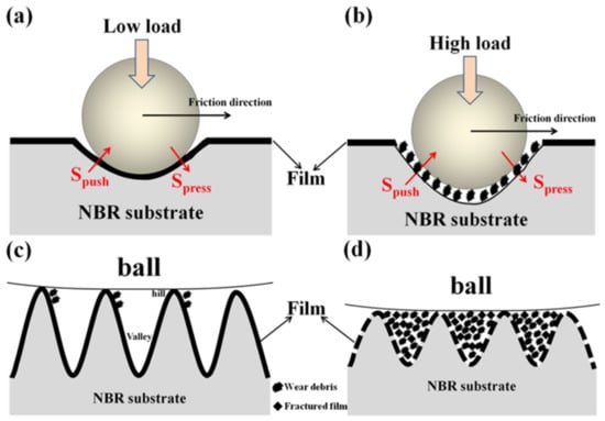
Figure 16.
Schematic diagram of frictional mechanism for DLC film coated NBR under (a,c) a low load and (b,d) a high load.
For the DLC-coated NBR, DLC film can significantly prevent the direct contact between NBR and steel counterpart, and thus reduce its adhesion due to the excellent chemical inertness of DLC film. Therefore, the effect of load on hysteresis component will mainly discuss in the following. Under a low load, the load is so small that the DLC film can maintain its lubrication function without brittle fracture during the friction. Therefore, the friction coefficient and wear rate of the sample is the lowest. From a microcosmic perspective, some stripes are always exited inevitably on the rubber surface because of its preparation technology. Under a low load, the load is so small that the wear mainly occurs at the “hill” of the stripes. Meanwhile, a small amount of wear debris fall on the side or “valley” of the sample stripes, namely, the debris did not result in the occurrence of abrasive wear as the third body, and thus the wear is minimal. However, under a high load, the sample undergoes severe deformation due to the brittle fracture of DLC film and loss of its load-bearing capacity. As a consequence, the hysteresis component increases although the contact area is larger at higher loads. Moreover, the fractured film is continuously crushed under the repeated load and a large amount of debris fills the “valley” of the sample stripes. At the same time, the samples are seriously deformed during the friction under a higher load, making these debris acts as a third body in the friction, resulting in a serious abrasive wear.
In addition, it is worth mentioning that the surface topography of samples and friction direction also influence its wear behaviors. Under a low load (1 N), wear occurs only at the “hill” of the stripes whatever the friction direction is parallel or perpendicular to the stripes, because the load is too low to cause a serious deformation of the sample. With the load increases to 4 N (or 7 N), it is not enough to cause the DLCs’ fracture and serious deformation of samples when the friction direction is parallel to the stripes (Figure 14b,c). At this time, the film can still maintain its lubricity function, while the wear only occurs at the “hill” of the stripes. But, when the friction direction is perpendicular to the stripes, these stripes can collide with each other under the action of the repeated load, resulting in the brittle fracture of the DLC film and the loss of its integrity (Figure 14f,g), which further leads to the loss of its load-bearing capacity and serious deformation of the sample. As a result, the wear rate is higher. However, when the friction load is further increased to 10 N, where the film can be fractured and the wear rate is the highest regardless of whether the friction direction is parallel or perpendicular to the stripes.
Based on the research results of this work, on the one hand, it can provide a basis for the design of the dynamic sealing rubber parts that the stripes of the dynamic sealing rubber should be parallel to the moving direction of the sealing co-pair on the basis of ensuring its tightness. On the other hand, researchers should focus on solving the brittleness of DLC films themselves in the design and preparation of DLC films on soft substrate in order to improve their lubrication under a high load. In other words, a high strength and super toughness DLC films should be needed to ensure its load-bearing capacity under a high load so as to maintain its lubrication.
4. Conclusions
Si interlayer/Si-DLC films were prepared on NBRs, and the influence of CH4 flow rate on the hardness, adhesion, and tribological behaviors of films on NBR were studied systematically, and then the sample with the best performance is selected to investigate its tribological behaviors and mechanism under the different contact loads. The results show that the hardness and H3/E2 ratio firstly decreases and then slightly increases resulting from the formation of Si-C bonds and its concentration, while the change trend of the friction coefficient and wear is consistent with that of the hardness. Meanwhile, the brittle fracture of films is the main reason for its high friction and wear under a higher load. Furthermore, the surface topography of films also plays an important role in influencing its friction and wear, and a lower wear rate can be observed when the friction direction is parallel to the stripe rather than perpendicular to it. This work provides a basis and reference for the design of the dynamic sealing rubber part and its surface protecting coatings under a high load for a wide range of tribological application under harsh conditions.
Author Contributions
Conceptualization, G.L. and L.Q.; methodology, Z.W. (Zedong Wen) and G.L.; software, K.C. and L.Q.; validation, G.L. and L.Q.; formal analysis, L.Q. and B.Z.; investigation, G.L. and Z.W. (Zedong Wen); resources, Z.W. (Zedong Wen); data curation, G.L.; writing—original draft preparation, G.L.; writing—review & editing, G.L., K.C., L.D., and Z.W. (Zhenlu Wang); supervision, G.L.; project administration, G.L.; funding acquisition, G.L. All authors have read and agreed to the published version of the manuscript.
Funding
This research was funded by the National Natural Science Foundation of China (Grant No. 51865025, U1737213) and Science and Technology Planning Project of Gansu Province (18JR3RA218, 18JR3RA223, 18JR3RA225), Scientific Research Project of Bureau of Gansu Education (2018A-104, 2019A-134) and Scientific Research Project of Lanzhou science and technology bureau (2018-4-32) And The APC was funded by the National Natural Science Foundation of China (Grant No. 51865025).
Acknowledgments
The authors wish to thank especially Sancheng Yu for providing the NBR substrates. The help rendered by the other colleagues and students in writing assistance of this manuscript and other aspects is also gratefully acknowledged.
Conflicts of Interest
The authors declare no conflict of interest.
References
- Bhaskaran, H.; Gotsmann, B.; Sebastian, A.; Drechsler, U.; Lantz, M.A.; Despont, M.; Jaroenapibal, P.; Carpick, R.W.; Chen, Y.; Sridharan, K. Ultralow nanoscale wear through atom-by-atom attrition in silicon-containing diamond-like carbon. Nat. Nanotechnol. 2010, 5, 181–185. [Google Scholar] [CrossRef] [PubMed]
- Aijaz, A.; Ferreira, F.; Oliveira, J.; Kubart, T. Mechanical Properties of Hydrogen Free Diamond-Like Carbon Thin Films Deposited by High Power Impulse Magnetron Sputtering with Ne. Coatings 2018, 8, 385. [Google Scholar] [CrossRef]
- Erdemir, A.; Ramirez, G.; Eryilmaz, O.L.; Narayanan, B.; Liao, Y.F.; Kamath, G.; Sankaranarayanan, S.K.R.S. Carbon-based tribofilms from lubricating oils. Nature 2016, 536, 67–71. [Google Scholar] [CrossRef] [PubMed]
- Liu, X.Q.; Yang, J.; Hao, J.Y.; Zheng, J.Y.; Gong, Q.Y.; Liu, W.M. A near-frictionless and extremely elastic hydrogenated amorphous carbon film with self-assembled dual nanostructure. Adv. Mater. 2012, 24, 4614–4617. [Google Scholar] [CrossRef]
- Hatada, R.; Flege, S.; Ashraf, M.N.; Timmermann, A.; Schmid, C.; Ensinger, W. The Influence of Preparation Conditions on the Structural Properties and Hardness of Diamond-Like Carbon Films, Prepared by Plasma Source Ion Implantation. Coatings 2020, 10, 360. [Google Scholar] [CrossRef]
- Hatada, R.; Flege, S.; Rimmler, B.; Dietz, C.; Ensinger, W.; Baba, K. Surface Structuring of Diamond-Like Carbon Films by Chemical Etching of Zinc Inclusions. Coatings 2019, 9, 125. [Google Scholar] [CrossRef]
- Nakahigashi, T.; Tanaka, Y.; Miyake, K.; Oohora, H. Properties of flexible DLC film deposited by amplitude-modulated RF P-CVD. Tribol. Int. 2004, 37, 907–912. [Google Scholar] [CrossRef]
- Miyakawa, N.; Minamisawa, S.; Takikawa, H.; Sakakibara, T. Physical–chemical hybrid deposition of DLC film on rubber by T-shape filtered-arc-deposition. Vacuum 2004, 73, 611–617. [Google Scholar] [CrossRef]
- Takikawa, H.; Miyakawa, N.; Minamisawa, S.; Sakakibara, T. Fabrication of diamond-like carbon film on rubber by T-shape filtered arc-deposition under the influence of various ambient gases. Thin Solid Films 2004, 457, 143–150. [Google Scholar] [CrossRef]
- Aoki, Y.; Ohtake, N. Tribological properties of segment-structured diamond-like carbon films. Tribol. Int. 2004, 37, 941–947. [Google Scholar] [CrossRef]
- Yoshida, S.; Okoshi, M.; Inoue, N. Femtosecond-pulsed laser deposition of diamond-like carbon films onto silicone rubber. J. Phys. Conf. Ser. 2007, 59, 368–371. [Google Scholar] [CrossRef]
- Tsubone, D.; Hasebe, T.; Kamijo, A.; Hotta, A. Fracture mechanics of diamond-like carbon (DLC) films coated on flexible polymer substrates. Surf. Coat. Technol. 2007, 201, 6423–6430. [Google Scholar] [CrossRef]
- Pei, Y.T.; Bui, X.L.; De Hosson, J.T.M. Flexible protective diamond-like carbon film on rubber. Scr. Mater. 2010, 63, 649–652. [Google Scholar] [CrossRef]
- Martinez-Martinez, D.; van der Pal, J.P.; Pei, Y.T.; De Hosson, J.T.M. Performance of diamond-like carbon-protected rubber under cyclic friction. II. Influence of substrate viscoelasticity on the friction evolution. J. Appl. Phys. 2011, 110, 124907. [Google Scholar] [CrossRef]
- Martinez-Martinez, D.; van der Pal, J.P.; Pei, Y.T.; De Hosson, J.T.M. Performance of diamond-like carbon-protected rubber under cyclic friction. I. Influence of substrate viscoelasticity on the depth evolution. J. Appl. Phys. 2011, 110, 124906. [Google Scholar] [CrossRef]
- Pei, Y.T.; Martinez-Martinez, D.; van der Pal, J.P.; Bui, X.L.; Zhou, X.B.; De Hosson, J.T.M. Flexible diamond-like carbon films on rubber: Friction and the effect of viscoelastic deformation of rubber substrates. Acta Mater. 2012, 60, 7216–7225. [Google Scholar] [CrossRef]
- Pei, Y.T.; Bui, X.L.; van der Pal, J.P.; Martinez-Martinez, D.; Zhou, X.B.; De Hosson, J.T.M. Flexible diamond-like carbon films on rubber: On the origin of self-acting segmentation and film flexibility. Acta Mater. 2012, 60, 5526–5535. [Google Scholar] [CrossRef]
- Lubwama, M.; Corcoran, B.; Kirabira, J.B.; Sebbit, A. Adhesion and composite micro-hardness of DLC and Si-DLC films deposited on nitrile rubber. Surf. Coat. Technol. 2012, 206, 4881–4886. [Google Scholar] [CrossRef]
- Lubwama, M.; Corcoran, B.; Rajani, K.V.; Wong, C.S. Raman analysis of DLC and Si-DLC films deposited on nitrile rubber. Surf. Coat. Technol. 2013, 232, 521–527. [Google Scholar] [CrossRef]
- Lubwama, M.; Corcoran, B.; McDonnell, K.A.; Dowling, D. Flexibility and frictional behaviour of DLC and Si-DLC films deposited on nitrile rubber. Surf. Coat. Technol. 2014, 239, 84–94. [Google Scholar] [CrossRef]
- Lubwama, M.; McDonnell, K.A.; Kirabira, J.B.; Sebbit, A.; Sayers, K. Characteristics and tribological performance of DLC and Si-DLC films deposited on nitrile rubber. Surf. Coat. Technol. 2012, 206, 4585–4593. [Google Scholar] [CrossRef]
- Evaristo, M.; Fernandes, F.; Cavaleiro, A. Room and High Temperature Tribological Behaviour of W-DLC Coatings Produced by DCMS and Hybrid DCMS-HiPIMS Configuration. Coatings 2020, 10, 319. [Google Scholar] [CrossRef]
- Nißen, S.; Heeg, J.; Wienecke, M.; Behrend, D.; Warkentin, M.; Rokosz, K.; Gaiaschi, S.; Chapon, P. Surface Characterization and Copper Release of a-C:H:Cu Coatings for Medical Applications. Coatings 2019, 9, 119. [Google Scholar] [CrossRef]
- Kanda, K.; Suzuki, S.; Niibe, M.; Hasegawa, T.; Suzuki, T.; Saitoh, H. Local Structure Analysis on Si-Containing DLC Films Based on the Measurement of C K-Edge and Si K-Edge X-ray Absorption Spectra. Coatings 2020, 10, 330. [Google Scholar] [CrossRef]
- Hatada, R.; Flege, S.; Ensinger, W.; Hesse, S.; Tanabe, S.; Nishimura, Y.; Baba, K. Preparation of Aniline-Based Nitrogen-Containing Diamond-Like Carbon Films with Low Electrical Resistivity. Coatings 2020, 10, 54. [Google Scholar] [CrossRef]
- Fujimoto, S.; Ohtake, N.; Takai, O. Mechanical properties of silicon-doped diamondlike carbon films prepared by pulse-plasma chemical vapor deposition. Surf. Coat. Technol. 2011, 206, 1011–1015. [Google Scholar] [CrossRef]
- Zhang, T.F.; Pu, J.J.; Xia, Q.X.; Son, M.J.; Kim, K.H. Microstructure and nano-wear property of Si-doped diamond like carbon films deposited by a hybrid sputtering system. Mater. Today Proc. 2016, 3, S190–S196. [Google Scholar] [CrossRef]
- Jiang, J.; Wang, Y.; Du, J.; Yang, H.; Hao, J. Properties of a-C:H:Si thin films deposited by middle-frequencymagnetron sputtering. Appl. Surf. Sci. 2016, 379, 516–522. [Google Scholar] [CrossRef]
- Wang, Z.; Wang, C.B.; Zhang, B.; Zhang, J.Y. Ultralow friction behaviors of hydrogenated fullerene-like carbon films: Effect of normal load and surface tribochemistry. Tribol. Lett. 2011, 41, 607–615. [Google Scholar] [CrossRef]
- Scharf, T.W.; Prasad, S.V. Solid lubricants: A review. J. Mater. Sci. 2013, 48, 511–531. [Google Scholar] [CrossRef]
- Wu, Y.; Li, H.; Ji, L.; Ye, Y.; Chen, J.; Zhou, H. Vacuum tribological properties of a-C:H film in relation to internal stress and applied load. Tribol. Int. 2014, 71, 82–87. [Google Scholar] [CrossRef]
- Erdemir, A. The role of hydrogen in tribological properties of diamond-like carbon films. Surf. Coat. Technol. 2001, 146–147, 292–297. [Google Scholar] [CrossRef]
- Sanchez-Lopez, J.C.; Erdemir, A.; Donnet, C.; Rojas, T.C. Friction-induced structural transformations of diamond like carbon coatings under various atmospheres. Surf. Coat. Technol. 2003, 163–164, 444–450. [Google Scholar] [CrossRef]
- Jiang, J.; Zhang, S.; Arnell, R.D. The effect of relative humidity on wear of a diamond-like carbon coating. Surf. Coat. Technol. 2003, 167, 221–225. [Google Scholar] [CrossRef]
- Rabbani, F. Phenomenological evidence for the wear-induced graphitization model of amorphous hydrogenated carbon coatings. Surf. Coat. Technol. 2004, 184, 194–207. [Google Scholar] [CrossRef]
- Scharf, T.W.; Singer, I.L. Monitoring transfer films and friction instabilities with in situ Raman tribometry. Tribol. Lett. 2003, 14, 3–8. [Google Scholar] [CrossRef]
- Martinez-Martinez, D.; Schenkel, M.; Pei, Y.T.; Sánchez-López, J.C.; De Hosson, J.T.M. Microstructure and chemical bonding of DLC films deposited on ACM rubber by PACVD. Surf. Coat. Technol. 2011, 205, S75–S78. [Google Scholar] [CrossRef]
- Nakazawa, H.; Kamata, R.; Miura, S.; Okuno, S. Effects of frequency of pulsed substrate bias on structure and properties of silicon-doped diamond-like carbon films by plasma deposition. Thin Solid Films 2015, 574, 93–98. [Google Scholar] [CrossRef]
- Nakazawa, H.; Miura, S.; Nakamura, K.; Nara, Y. Impacts of substrate bias and dilution gas on the properties of Si incorporated diamond-like carbon films by plasma deposition using organosilane as a Si source. Thin Solid Films 2018, 654, 38–48. [Google Scholar] [CrossRef]
- Wu, Y.X.; Zhang, S.J.; Yu, S.W.; Zhu, L.N.; Shen, Y.Y.; Zhou, B.; Tang, B.; Liu, Y. A self-lubricated Si incorporated hydrogenated amorphous carbon (a-C:H) film in simulated acid rain. Diam. Relat. Mater. 2019, 94, 43–51. [Google Scholar] [CrossRef]
- Wang, J.J.; Pu, J.B.; Zhang, G.A.; Wang, L.P. Tailoring the structure and property of silicon-doped diamond-like carbon films by controlling the silicon content. Surf. Coat. Technol. 2013, 235, 326–332. [Google Scholar] [CrossRef]
- Bui, X.L.; Pei, Y.T.; De Hosson, J.T.M. Magnetron reactively sputtered Ti-DLC coatings on HNBR rubber: The influence of substrate bias. Surf. Coat. Technol. 2008, 202, 4939–4944. [Google Scholar] [CrossRef]
- Lux, H.; Edling, M.; Lucci, M.; Kitzmann, J.; Villringer, C.; Siemroth, P.; Matteis, F.D.; Schrader, S. The Role of Substrate Temperature and Magnetic Filtering for DLC by Cathodic Arc Evaporation. Coatings 2019, 9, 345. [Google Scholar] [CrossRef]
- Grein, M.; Gerstenberg, J.; von der Heide, C.; Bandorf, R.; Bräue, G.; Dietzel, A. Niobium-Containing DLC Coatings on Various Substrates for Strain Gauges. Coatings 2019, 9, 417. [Google Scholar] [CrossRef]
- Bociaga, D.; Guzenda, A.S.; Szymanski, W.; Jedrzejczak, A.; Jastrzebsk, A.; Olejnik, A.; Jastrzebski, K. Mechanical properties, chemical analysis and evaluation of antimicrobial response of Si-DLC coatings fabricated on AISI 316 LVM substrate by a multi-target DC-RF magnetron sputtering method for potential biomedical applications. Appl. Surf. Sci. 2017, 417, 23–33. [Google Scholar] [CrossRef]


© 2020 by the authors. Licensee MDPI, Basel, Switzerland. This article is an open access article distributed under the terms and conditions of the Creative Commons Attribution (CC BY) license (http://creativecommons.org/licenses/by/4.0/).