Review

Toughening Mechanism of Mullite Matrix Composites: A Review

1
School of Metallurgical Engineering, Anhui University of Technology, Maanshan 243002, China
2
College of Material Science and Engineering, Chongqing University, Chongqing 400030, China
*
Author to whom correspondence should be addressed.
Coatings 2020, 10(7), 672; https://doi.org/10.3390/coatings10070672
Submission received: 7 June 2020 / Revised: 9 July 2020 / Accepted: 10 July 2020 / Published: 14 July 2020
(This article belongs to the Section Surface Characterization, Deposition and Modification)

Abstract

:
Mullite has high creep resistance, low thermal expansion coefficient and thermal conductivity, excellent corrosion resistance and thermal shock resistance, and plays an important role in traditional ceramics and advanced ceramic materials. However, the poor mechanical properties of mullite at room temperature limit its application. In order to improve the strength and toughness of mullite, the current research focuses on the modification of mullite by using the second phase. The research status of discontinuous phase (particle, whisker, and chopped fiber) and continuous fiber reinforced mullite matrix composites is introduced, including preparation process, microstructure, and its main properties. The reinforcement mechanism of second phase on mullite matrix composites is summarized, and the existing problems and the future development direction of mullite matrix composites are pointed out and discussed.

1. Introduction

Mullite ceramics have higher creep resistance, good thermal shock resistance, and less strength attenuation at high temperatures, which has attracted the attention of scholars all over the world [1]. In recent years, with the continuous progress and improvement of industrial technology, mullite refractories have developed rapidly and are widely used in aerospace, metallurgy, petroleum, chemical, and other industries. In addition, mullite ceramics also have excellent electrochemical and optical properties, such as broadband infrared and radar wave transmittance, etc. They can be used in electronic packaging, infrared wave transmittance, high-temperature optical windows, and other fields [2,3,4,5,6,7,8].
However, the poor mechanical properties of mullite ceramics at room temperature limit their application. Most researchers have tried to solve this problem by introducing second phase enhancers (such as particles, whiskers, fibers, etc.), and they have achieved many good results. Sarkar et al. [9] reported a zirconia reinforced mullite matrix composites by electrophoretic deposition (EPD) technology. After testing, the fracture toughness of the samples was up to 5.5 MPa·m1/2, which was significantly higher than that of monolithic mullite matrix. Takada et al. [10] reported a mullite-based composites by sintering nano-sized SiC particles. The mechanical properties of the composites were significantly improved, the fracture toughness and fracture strength of the composites were 2.7 and 490 MPa, respectively, both of which were higher than the mechanical properties of pure mullite materials. Huang et al. [11] used 30 vol.%-SiC whisker reinforced mullite to prepare composite materials by spark plasma sintering (SPS) sintering technology, the fracture toughness and strength of the composite materials were 4.5 and 570 MPa, respectively. The mechanical properties of them were more than double that of pure mullite. Iwata et al. [12] used one-dimensional directional arrangement of continuous C fiber reinforced and toughened mullite to prepare composite by winding hot pressing process. The fracture toughness and bending strength of the composite reached 18 MPa·m1/2 and 600 MPa respectively, which were greatly improved compared with monomer mullite ceramics.
Although there have been some research papers and reviews on mullite and mullite composites [1,13,14,15], there are few summaries on the strengthening methods and strengthening mechanisms of mullite-based composites. In this paper, the preparation methods of mullite composites are reviewed. In addition, the research status and reinforcement mechanism of several typical mullite-based composites are analyzed and discussed in detail, and the development of mullite-based composites is also prospected. The purpose of this review is to briefly introduce and provide some useful references for new researchers in this field.

2. Physical and Chemical Properties of Mullite

Mullite belongs to the compositional series of orthorhombic aluminosilicates, and the change of aluminum to silicon ratios is related to the solid solution series Al4+2xSi2−2xO10−x [16,17], with x ranging from 0.2 and 0.9 (the alumina content is about 50%–90% [18]). When x = 0 (Al2O3 to SiO2 ratio is 1), the series presents the polymorphs (Al2SiO5), such as kyanite, andalusite, and sillimanite. When x = 1, it leads to a silica-free phase, also known as iota-alumina or ι-Al2O3 [14]. However, mullite phases observed so far fall into the range 0.18 ≤ x ≤ 0.88 [18], such as 3/2 mullite (3Al2O3·2SiO2, x = 0.25), 2/1 mullite (2Al2O3·SiO2, x = 0.40), 4/1 mullite (4Al2O3·SiO2, x = 0.67), and 9/1 mullite (9Al2O3·SiO2, x = 0.842) [14,19]. The types of mullite depend largely on their synthesis procedures, which can be summarized as follows:
  • Sinter-mullites depend mainly on the solid reaction between the raw materials at 1600–1700 °C, and the enhancement in sintering is imputed to a liquid phase formation. These mullites tend to be “stoichiometric”, i.e., 3/2-composition (3Al2O3·2SiO2, i.e., ≈72 wt.% Al2O3, x = 0.25).
  • Fused-mullites are formed by crystallizing aluminum silicate melt. These mullites tend to be rich in Al2O3, and their composition is close to 2/1 (2Al2O3·SiO2, i.e., ≈78 wt.% Al2O3, x = 0.40).
  • Chemical-mullites are produced by heat treatment of organic or inorganic precursors. The composition is strongly dependent on raw materials and treatment temperature. Al2O3-rich compounds have been identified at synthesis temperatures below 1000 °C (>90 wt.% Al2O3, x > 0.80).
The crystal structure of mullite can be described by sillimanite structure (Al2SiO5), as shown in Figure 1. The key features of the crystal structure of sillimanite are edge-sharing octahedral AlO6 chains running parallel to the c-axis [20]. It can be seen that the octahedral chains are linked by double chains of corner-sharing MO4 tetrahedra (also parallel c), with an ordered distribution of the tetrahedral cations Al3+ and Si4+. Unlike the case perpendicular to the c-axis, the order of AlO6 octahedron and AlO4 and SiO4 tetrahedron appears parallel to the a-axis and the b-axis. The average structure of mullite can be obtained from the average structure of sillimanite through the coupling substitution of Al3+tet (tet = tetrahedral) for Si4+tet and the simultaneous disorder of Al3+ and Si4+ at tetrahedral site. The excess negative charge in mullite produced by replacing Si4+ with Al3+ is compensated [20]. It includes the removal of O atoms bridging two adjacent tetrahedra in the sillimanite structure, with the number of vacancies corresponding to the x-value of the general formula of the mullite-type alumino silicates Al4+2xSi2−2xO10−x. The formation of vacancies causes the associated tetrahedral position TS to shift to a position designated TS*, so that the previously bridged O(C) oxygen atom becomes tricoordinated and forms a T3O group. The so-called tetrahedral triclusters, TS*, the TS position is favorably occupied by Al.
The properties of mullite are controlled by its crystal structure. For example, the mechanical and thermal properties are directly affected by the special structure and cross-linkage of the principal bond chains. In addition, mullite material also has excellent creep resistance at high temperature with small plastic deformation. This is mainly attributed to the fact that tightly octahedral chains and tetrahedral double chains parallel to the c-axis of crystallography hinder the expansion of deformation [13]. The strong bonding due to the intensive overlapping of orbitals in parallel c-axis lattice direction, which results in the mullite materials present high mechanical stiffness and low compressibility, the high thermal and electrical conductivity. However, mullite with a complex or distorted crystal structure exhibits a tendency to heat scatter, which reduces the thermal conductivity. On the other hand, the presence of O vacancies weakens the structure: the average elastic hardness of mullite is lower than that of sillimanite without O vacancies. Moreover, they believe that the configuration entropy is caused by the disorder of mullite’s internal structure stabilizes the structure at high temperatures [13].
Compared with other materials, mullite ceramics show good comprehensive properties, as shown in Table 1 [15]. It can be seen that mullite ceramics have low thermal expansion, high thermal stability, and high creep resistance, electrical conductivity, and corrosion stability, which have good application potential in the fields of high temperature thermal structure materials and thermal protection. However, mullite ceramics have poor fracture toughness and bending strength, especially the fracture toughness is only about 2 MPa·m1/2.
The problem of poor mechanical properties of mullite at room temperature is solved by the designability of composite materials. In recent years, reducing intrinsic brittleness and improving mechanical properties are the research objectives of mullite-based composites. The high-quality second phase reinforcing materials are used to improve the mechanical properties of mullite matrix composites [21,22,23]. In order to improve the fracture toughness and bending strength of mullite materials, the high strength SiC whiskers (SiCW) and ZrO2 particles (ZrO2,P) are added to mullite matrix composites, and shown in Figure 2. It can be seen that the reinforcement of SiCW on mechanical properties of mullite is significantly better than that of ZrO2,P. The fracture toughness and bending strength of the composite materials increase significantly with the increase of the SiCW content. The fracture toughness and bending strength of SiCW/mullite composites range from 3.5 to 7 MPa·m1/2 and 400 to 900 MPa respectively, which are significantly higher than the strength of monolithic mullite [24].

3. Application of Mullite and Mullite Matrixcomposites

Mullite and mullite matrix ceramics exhibit a variety of appearance, such as Czochralski-grown single crystals, polycrystalline, and multiphase ceramics. As Shown in Figure 3a, this is a large, uniform, non-inclusion, and optically transparent mullite single crystal grown by Czochralski method by Berlin Crystal Growth Research Institute [13]. As Shown in Figure 3b, this is a typical polycrystalline mullite ceramic, the average grain size is about 2 μm [25]. It can be made into very large refractory products, as well as very small and high purity engineering components. Polycrystalline mullite ceramics mainly include monolithic mullite ceramics, mullite matrix composites, and mullite coatings [15].
Monolithic mullite ceramics are considered as a good high-temperature structural material, which are widely used in the aerospace [26], metallurgy [27,28], petroleum [24], chemical [29], and other industries. In addition, mullite ceramics also have excellent electrochemical and optical properties, such as broadband infrared and radar wave transmittance, etc. They can be used in electronic packaging (Figure 4a), infrared wave transmittance, high-temperature optical windows (Figure 4b), and other fields [2,3,4,5,6,7,8]. Many metals and ceramics are easily degraded under high temperature reduction and oxidation environments [1,2,3]. Surface coating technology is used to protect these materials at high temperatures [4,5,30,31,32,33,34,35], so-called environmental barrier coatings (EBCs) [36,37]. Mullite EBCs have been successfully used for high temperature oxidation protection of oxide or non-oxide based ceramics, as shown in Figure 4c [15]. Moreover, discontinuous phases such as particles (SiC, ZrO2, and Al2O3), whiskers (SiCW and MuW) and chopped fibers (Cf, SiCf, and Al2O3,f) are widely used in the preparation of mullite composites. Reinforced mullite ceramics are often used as industrial refractories because of their high refractory, good thermal shock resistance, chemical erosion resistance, creep resistance, etc. As shown in Figure 4d, a zirconia mullite refractory is used in the glass industry [38]. Alumina-mullite ceramics with low glass phase content have good hardness and strength, and have high armor and wear resistance application potential [39]. Figure 4e is typical ballistic armor of alumina-mullite ceramics. At present, continuous fiber strengthening is considered to be the most effective strengthening method for mullite ceramics. It can not only improve the strength and toughness significantly, but also be suitable for the preparation of complex components [40,41,42,43]. In particular, alumina fibers and mullite fibers are used to reinforce mullite-based composites. These mullite-based composites are widely used as thermal protection materials for combustors and aircraft gas turbine engines, as shown in Figure 4f [15].

4. Modification and Reinforcement Methods of Mullite Ceramics

4.1. Preparation Method of Discontinuous Phase Reinforced Mullite

Reinforcements materials such as particles, whiskers, chopped fibers, etc. are discontinuously distributed in mullite matrix, and the preparation method and performance improvement in preparing mullite composites reinforced by these materials are similar [44,45,46,47,48,49]. In the 1980s, SiC, ZrO2 and Al2O3 particles as the second phase are used to enhance mullite ceramics. The monocrystalline whiskers mainly represented by SiC whiskers and mullite whiskers appeared in the 1990s have the advantages of few defects, high strength and large aspect ratio, and they have better reinforcement effect on mullite matrix than the second phase particles (SPPs). Chopped fibers are similar to whiskers, mainly including C, SiC, Al2O3 fibers, etc.
The preparation method of particle reinforced mullite matrix composites is uniformly mixing mullite or Al2O3 + SiO2 powder with reinforced phase particles and then carrying out high temperature reaction sintering. The sintering temperature, particle size and uniformity of mixture are the main effect factors for sintering quality. At present, many methods are carried out to increase the density of mullite matrix composites. Such as improving sintering process, reducing particle size and raising the mixing uniformity of mixture, adding sintering additives, and improving the kinetic condition of sintering reaction.
Advanced sintering methods mainly include hot-pressing sintering, spark plasma sintering (SPS), microwave assisted sintering [50,51,52], high temperature self-propagating reaction sintering (SHS) [53], etc. In order to obtain a mixture with more similar particle size, higher mixing uniformity and better reactivity, the chemical method is considered as a more effective method than mechanical mixing method [54]. The chemical methods mainly consist of hydrolytic precipitation and sol-gel method. The micro powder with finer particle size and high reactivity can be obtained by chemical method, which can effectively improve the sintering quality [55]. Wang et al. [56] reported a silica sol and aluminum nitrate coprecipitation method, and the highly reactivity micro powder are prepared successfully. The mullite sintering temperature of this micro-powder is only 1250 °C, and the density can reach 98.5% at 1550 °C. In addition, the sintering quality of mullite can be improved by adding sintering additives, such as Y2O3 [57], V2O5 [58], Sc2O3 [59], etc.
The activation center is formed by transient viscous sintering (TVS) [60] or adding mullite seed [61] to reduce the activation energy of sintering. Griggio studied the crystallization kinetics of mullite by a silicone resin filled with commercial γ-alumina nanoparticles, and the reaction temperature were 1250–1350 °C [62]. It was found that the SiO2 formed by the decomposition of silicone resin was coated on the surface of Al2O3 particles, and this process has a lower activation energy values comparing with the sol-gel precursors.
The preparation of SiCW/Mullite composites is similar to that of SiCP/Mullite, which mainly includes solid reaction and hot pressing sintering [63]. MuW/Mullite composites are generally prepared by in-situ whisker method [64,65]. The mechanism of this method is preparing a uniform mixture of Al2O3 and SiO2 fine powder, adding fluoride on this basis, and then catalyzing the growth of whiskers to form densified composites. Chopped fiber reinforced method is also a traditional enhancement method for mullite matrix composites, in addition to sol impregnation [66], electrophoretic deposition [67], and other methods.

4.2. Preparation Method of Continuous Fiber Reinforce Mullite

Continuous fiber reinforced mullite matrix composites are generally prepared by impregnation method. It can be divided into slurry impregnation process, sol-gel process, pyrolysis (PIP) process, precursor infiltration, and chemical vapor infiltration (CVI) process according to different application forms (nonwoven, woven, and three-dimensional woven). At the same time, other measures can be adopted to assist, such as pressurization, oscillation, electrophoretic deposition (EPD), etc. [68,69,70].
  • Slurry Impregnation Process
This method is mainly applicable to the laminated structure of nonwoven cloth and woven cloth. The continuous fiber bundle or woven cloth is mixed with the slurry prepared by ceramic micropowder and binder, then dried and cut, and then dried and pretreated after lamination in a mold and pressurized. When the sintering temperature approaches or exceeds the softening point of the glass phase, which is helpful for densification of the composite material. The composites prepared by this process have the characteristics of low porosity, high density and good mechanical properties. In addition, the process has the advantages of short preparation period, high efficiency and controllable volume fraction of the enhancement phase. However, the main disadvantages of this process are high sintering temperature, large fiber damage, uneven distribution of reinforcing phase, easy lamination of fibers, and not suitable for preparing complex shaped components [71].
  • Sol-Gel Process
Sol-gel process is to hydrolyze inorganic salts or metal alcohol-oxy groups to form sol directly, or to depolymerize them to form sol, and then put fiber preforms in the sol to form gel through further hydrolysis and condensation, and the composite material is formed after the gel is dried and heat treated [72,73]. At last, the highly densified carbon fiber mullite matrix composites and silicon carbide fiber mullite matrix composites are obtained. And the highly densified composites with unmullitized matrices consisting of a-alumina particles in silica glass are also prepared [74,75]. This process can reduce the thermal damage of the fibers because of the high particle activity, uniform dispersion of the particles in the sol and the low preparation temperature of the composite material.
  • Precursor Infiltration and Pyrolysis (PIP) Process
In this method, the three-dimensional braided preform is impregnated with organic precursor and converted into ceramic matrix after high temperature cleavage. The raw materials used in this method generally include Si(OC2H5)4 and Al(NO3)3, etc. [76]. This method is not limited by pressure conditions and can prepare components with complex shapes. Moreover, the fiber damage is less because the pyrolysis temperature of this method is lower. However, the disadvantage of this method is low efficiency, which requires repeated impregnation and cleavage.
  • Chemical Vapor Infiltration (Cvi) Process
CVI process is a practical method to prepare fiber reinforced ceramic matrix composites. In this process, the braided preform is placed in the reaction source gas, and decomposed or chemically deposited in the framework gap at the deposition temperature. The system generally includes AlCl3-SiCl4-H2-CO2, etc. [77]. Because of its low efficiency, this method is mainly used to prepare thinner structural composites or membrane materials or as an auxiliary densification method [78].

5. Toughening Mechanism of Mullite by Discontinuous Phase

5.1. Toughening Mechanism of Second Phase Particles

The operation of sintering densification and raw material homogenization is simpler in the preparation of particle toughened mullite matrix composites than in the preparation of mullite composites by chopped fibers or whiskers. Although the toughening effect of particles is not as good as that of whiskers and fibers, if the types, particle sizes and contents of particles are properly selected, they will still have certain toughening effect on the matrix, and the high temperature strength and high temperature creep properties of the matrix will also be improved. The second phase particles (SPPs) used for mullite enhancement mainly include ZrO2, SiC, etc. [79,80]. The toughening mechanism mainly includes transformation toughening, non-phase transformation toughening and nano-particle toughening.

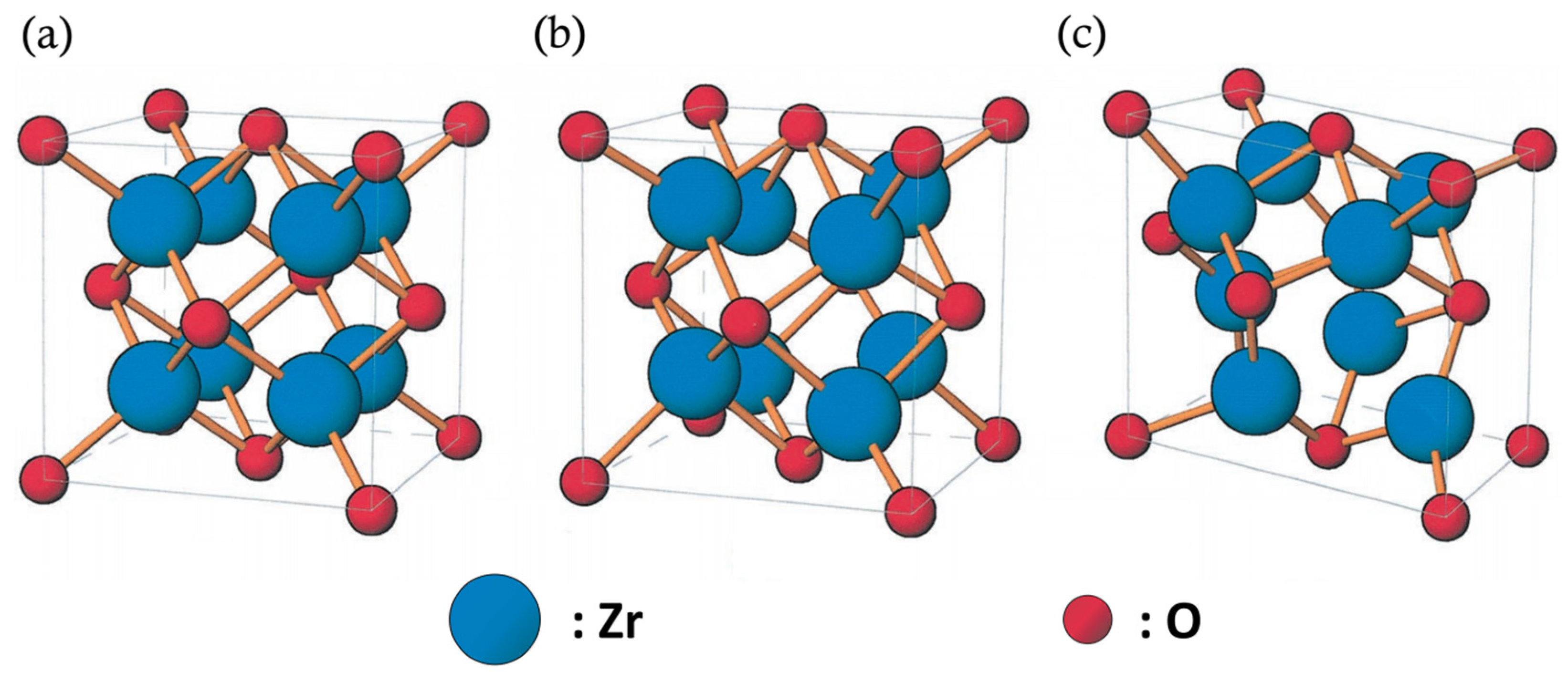
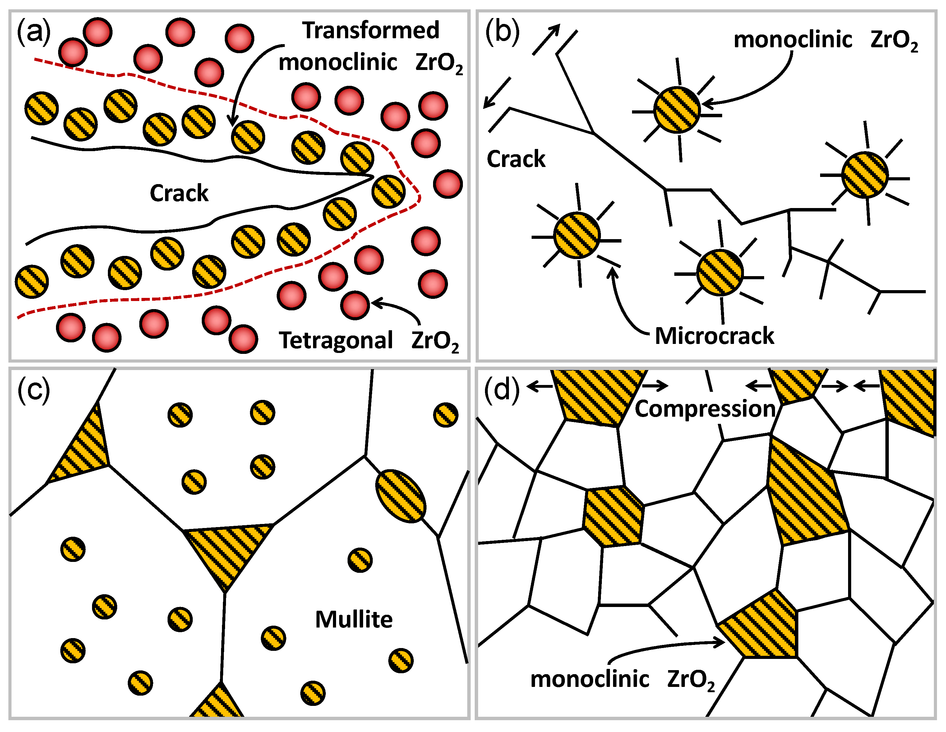
5.1.1. Phase Transformation Toughening Mechanism of ZrO2 Particles

Oxide-doped zirconia is a commonly used ceramic material, Zirconia (ZrO2) can significantly improve the thermal and mechanical properties of mullite ceramics through phase transformation toughening and microcrack toughening [81,82,83,84]. Ruh et al. [82] reported a Mullite-30% ZrO2 composites. The fracture toughness of the composites is nearly twice that of monolithic mullite. Yuan et al. [22] also reported a ZrO2 toughened mullite composite ceramics. The results show that the flexural strength and fracture toughness of the materials can increase by 15%–30% when the addition of ZrO2 (average size is 1 μm) is 10%–20%. Claussen et al. [85] believe that stress-induced phase transformation toughening mechanism exists in zirconia mullite composites, and microcracks also contribute to the improvement of material toughness. As shown in Figure 5, ZrO2 has three different crystal structures at different temperatures: cubic phase (c-ZrO2), tetragonal phase (t-ZrO2), and monoclinic phase (m-ZrO2) [80,86]. ZrO2 will undergo c→t→m isomerization when it is cooled from high temperature to room temperature, the volume expansion of 3%–5% and the shear strain of 7%–8% will occur during the transition from tetragonal phase to monoclinic phase. Significant microcrack toughening and residual stress toughening are caused by the phase transformation of ZrO2 itself, thus the toughness of the material is significantly improved.
Claussen et al. [85] prepared a zirconia reinforced mullite composites, most of the dislocation networks were observed at the grain boundaries, and only a few are found in the amorphous regions. It is proved that the composites has good grain boundary strength. Further evidence for the good grain-bound strategy was demarcated by their subsequent observations, and the fraction was almost completely transcristalline, splitting the ZrO2 particles. They concluded that the main reason for this fracture mode was the formation of microcracks in mullite matrix when ZrO2 particles changed from monoclinic crystal to tetragonal crystal during cooling, according to the observation of microcracks between ZrO2 particles in transmission electron microscope. The fracture toughness of the composite samples prepared by EPD technology by Metselaar [9] is 5.5 MPa·m1/2, which is significantly higher than that of pure mullite. The microscopic morphology of the prepared sample is shown in Figure 6a, and microcracks appear in the central region of the sample. Their research shows that the micro-cracks and crack closure caused by phase change toughening, which significantly improves the KIC of mullite/zirconia composites. This is due to the difference in average particles size, 0.3, 0.5, and 0.5 µm for alumina, silica, and zirconia, respectively, and thermal contraction and volume expansion mismatch during the phase transition of zirconia and the formation of mullite. Belhouchet [21] reported a zirconia dispersed mullite composites by reaction sintering method. Figure 6b show that the composites consist of irregular mullite grains and round zirconia grains, and zirconia is distributed between and within the grains. It can be seen that ZrO2 is mainly distributed on the grain boundaries of mullite with a particle size of 1–2 μm. In addition, a large number of fine ZrO2 particles were also observed inside the mullite grains with a particle size of 0.1–0.5 μm. The growth of mullite grain is inhibited by large sizes of ZrO2 particles pinning at the mullite grain boundaries. While the mechanical properties such as hardness, fracture strength and toughness of the mullite composites are effectively improved by the dispersion state of ZrO2 particles.
Therefore, the toughening mechanisms of ZrO2 are summarized as stress-induced phase transformation toughening, Zirconia incorporation toughening, microcrack toughening, and surface compression toughening, as shown in Figure 7 [22,24,87]. Under the action of the stress field at the crack tip, ZrO2 particles undergo tetragonal transformation to monoclinic transformation and absorb the energy, thus improving the fracture toughness. This is the stress induced phase transition, as shown in Figure 7a [88,89]. The microcrack toughening of ZrO2 is shown in Figure 7b, the ZrO2 particles maintain different critical sizes of tetragonal phase at room temperature in a different matrix. When a particle is larger than the critical size, tetragonal phase will change into monoclinic phase and form microcracks [9,90]. When the main crack extends around the ZrO2 particles, this uniformly distributed microcrack can ease the stress concentration at the tip of the main crack or bifurcate the main crack to absorb energy [91,92]. Adding metastable zirconia into mullite is the main reason for grain boundary strengthening, as shown in Figure 7c [21]. Moreover, the tetragonal ZrO2 particles on the surface of mullite specimens are transformed into monoclinic phase to form a compressed surface layer after volume expansion. This is surface compression toughening, as shown in Figure 7d [24]. However, the above mechanisms are not mutually exclusive, and which toughening mechanism plays a leading role in actual material use depending on the degree of tetragonal to monoclinic martensitic transformation and the location of phase transformation in the material.

5.1.2. Non-phase Transformation Toughening Mechanism of ZrO2 Particles

Research on non-phase transformation toughened mullite with second phase particles has been started for a long time, carbide and nitride are generally used for the second phase particle [93,94,95,96]. Chu et al. [86] reported a carbide ceramic particle dispersion reinforced mullite composites. They found that the fracture toughness of the composites increased by 45% compared to the monolithic mullite ceramics with the increase of TiC volume fraction. The results show that the improvement of fracture toughness is caused by residual stress and crack deflection, and the residual stress is caused by mismatch of the thermal expansion coefficient [97]. They also made SiC/mullite composites by hot pressing at 1650 °C [93]. Research shows that the addition of SiC particles prevents mullite grains from growing during hot pressing and significantly increases the fracture stress of the sample. As abnormally large grains are usually the cause of material fracture, the fracture stress of composite materials increases with the increase of SiC volume fraction.
Therefore, non-phase transformation toughening of ZrO2 particles is mainly caused by the mismatch of elastic modulus and thermal expansion coefficient between matrix and particles. In addition, because of the refinement of grain size, the number of grain boundaries will greatly increase, and the interface between the matrix and the second phase particles will greatly affect the toughening mechanism and strengthening effect. The length-diameter ratio of the second phase particles has obvious influence on crack deflection and will also play a role in toughening mullite. Therefore, the length-diameter ratio of the second phase particles should also be reasonably selected.

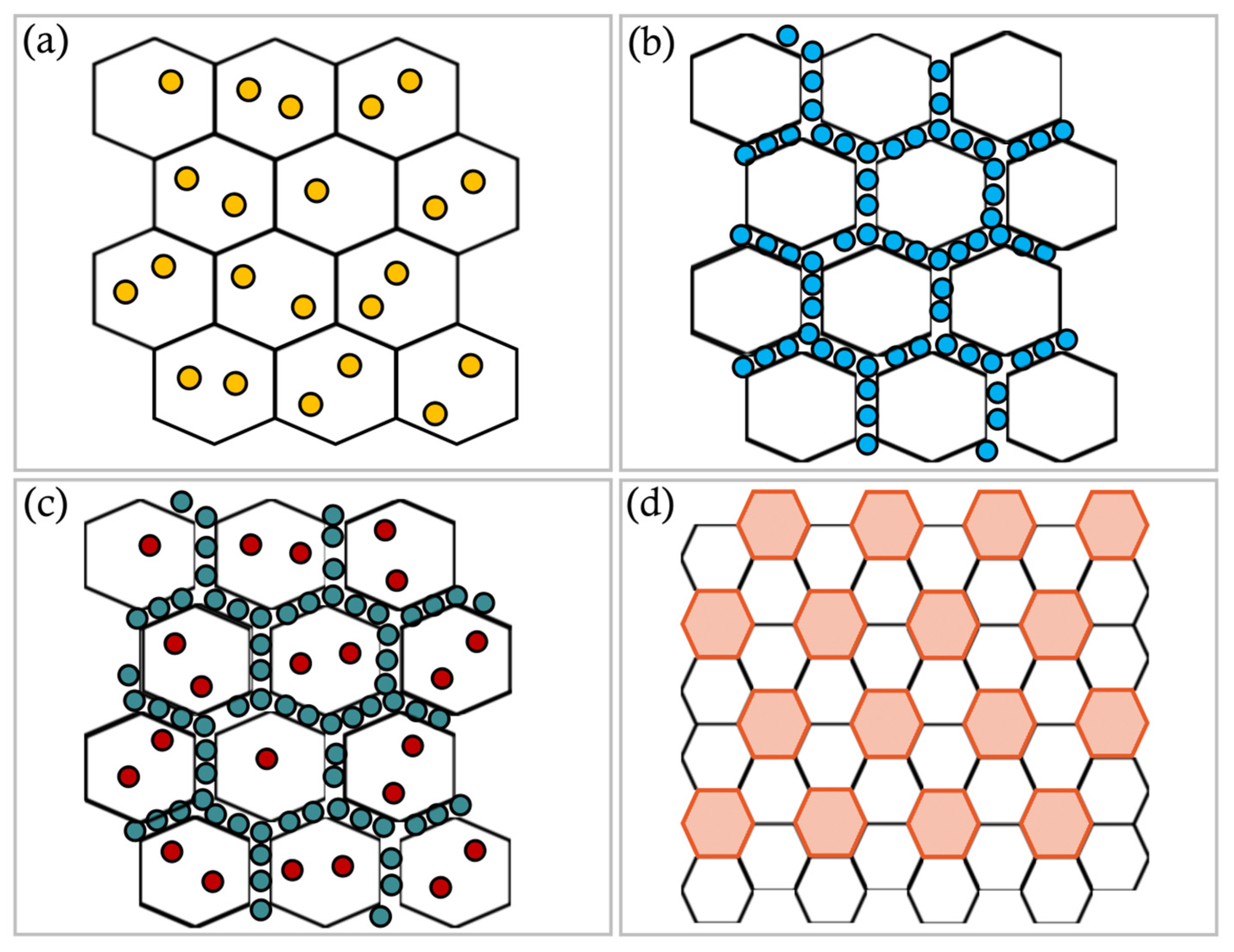
5.1.3. Toughening Mechanism of Nanoparticles

The appearance of nanotechnology has shown great advantages in improving the properties of traditional ceramic materials. Gustafsson et al. [25] studied the creep behavior of SiC reinforced mullite composites, and the typical microstructures of SiC reinforced mullite composites are shown in Figure 8, as shown in Figure 8a, it can be seen that most grain sections are equiaxial, and only a few thin and large grain interfaces are observed at the etching surface. As shown in Figure 8b, the mullite grains contained intragranular cavities also in this microstructure, and these cavities were usually faceted and less than 100 nm in diameter. The intragranular SiC particles did not form clusters, and were smaller, typically 10–50 nm, see Figure 8c. As shown in Figure 8d,e, The composites consists of mullite grains and fine SiC dispersed phase, and SiC grains (place indicated by arrow) are dispersed in the grain boundaries and mullite matrix. Some dislocations are generated by SiC particle pinning at intergranular and intragranular, or occur from intergranular and intergranular SiC particles.
Takada et al. [10] prepared a nano-SiC particle toughened mullite composites. The mechanical properties of composites are significantly higher than that of the monolithic mullite. The Vickers hardness, fracture toughness, and fracture strength are 10 GPa, 2.7 MPa·m1/2, and 490 MPa, respectively. This composites is composed of columnar mullite, fine SiC dispersed phase and amorphous grain boundary phase. Larger SiC particles are dispersed at grain boundaries, and finer SiC particles are distributed not only at grain boundaries but also in mullite matrix. This is consistent with Gustafsson’s research results [25].
The nanocomposites can be summarized into three types [98], intragranular and intergranular composites and nano/nanocomposite as shown in Figure 9. The nano-size particles are dispersed mainly within the matrix grains or at the grain boundaries of the matrices, and are shown in Figure 9a–c, respectively. Generally, nanoparticles are used to improve the mechanical properties of materials, such as hardness, fracture strength, room temperature toughness, high temperature strength, high temperature creep resistance and fatigue fracture resistance. On the other hand, the nano/nano composites are composed of the dispersoids and matrix grains with the nanometer-sizes, as shown in Figure 9d. The main application of this composite is to add new functions to ceramics such as metal machinability and superplasticity [99].
The enhancement of mullite ceramics is achieved by the dispersion of nanoparticles at intergranular and intragranular, as shown in Figure 9c. The mechanism of toughening and strengthening mullite with nano-size particles can be summarized as follows:
  • Fine Grain Strengthening Theory
The introduction of particle phase can inhibit the abnormal growth of matrix grains and make the matrix structure uniform and refined, which is one of the reasons for improving the strength and toughness of nano-ceramic composites [81].
  • Transgranular Theory
The “intragranular” structure can weaken the effect of the main grain boundary and induce transgranular fracture, resulting in transgranular fracture instead of intergranular fracture when the material is fractured [100,101,102].
  • Pinning Theory
The “pinning” effect of nanoparticles on matrix grain boundaries restricts the occurrence of grain boundary slip, voids and creep. Therefore, the “pinning” effect is the main reason why nanoparticles improve the high temperature strength of oxides [103].

5.2. Toughening Mechanism of Whisker

Ceramic whisker is a small ceramic single crystal with a certain aspect ratio and few defects, so it has high strength and is a high-quality toughening reinforcement for ceramic matrix composites. At present, SiC whiskers, Si3N4 whiskers, and Al2O3 whiskers are common ceramic whiskers, and the SiC whiskers are the most commonly used and have the best properties. SiCW is known as the “King of Whiskers” and has the advantages of high strength and high elastic modulus [104,105,106,107,108,109,110,111,112,113,114,115,116,117,118,119,120,121].
The fracture toughness, bending strength and other properties of the mullite matrix composites are obviously improved due to the addition of silicon carbide whiskers. Z.R. Huang et al. [11] reported a 30 vol.%-SiC whisker reinforced mullite composites by SPS sintering technology. The strength and fracture toughness of the composites are 570 MPa and 4.5 MPa·m1/2, respectively. The above mechanical properties are more than double that of pure mullite. Tamar et al. [112] prepared an Al2O3 whisker reinforced mullite composites by hot pressing sintering. When the whisker content in the composites is 30 vol.%, the fracture toughness of the composites is 1.5 times that of monolithic mullite. Hirata et al. [113] prepared a Si3N4/mullite whisker reinforced mullite composites. When the content of Si3N4 whisker is 10%, the fracture toughness of the samples increases from 1.3 to 4.3 MPa·m1/2. The addition of mullite whiskers also improves the fracture toughness of mullite. The average fracture toughness of composites with 5% and 10% mullite whiskers is 1.8 and 2.6 MPa·m1/2, respectively. In the Si3N4 whisker/mullite system, crack deflection and large pullout of Si3N4 whisker at fracture surface are observed. In mullite whisker/mullite system, it is observed that cracks deflect along mullite whisker or propagate forward through mullite whisker or propagate along mullite whisker direction. They concluded that the crack propagation or crack-whisker interaction has a good correlation with the fracture toughness value of the composite material.
Therefore, the main toughening mechanisms of whiskers to mullite can be summarized as follows: crack bridging, crack deflection, and pullout effect, as shown in Figure 10.
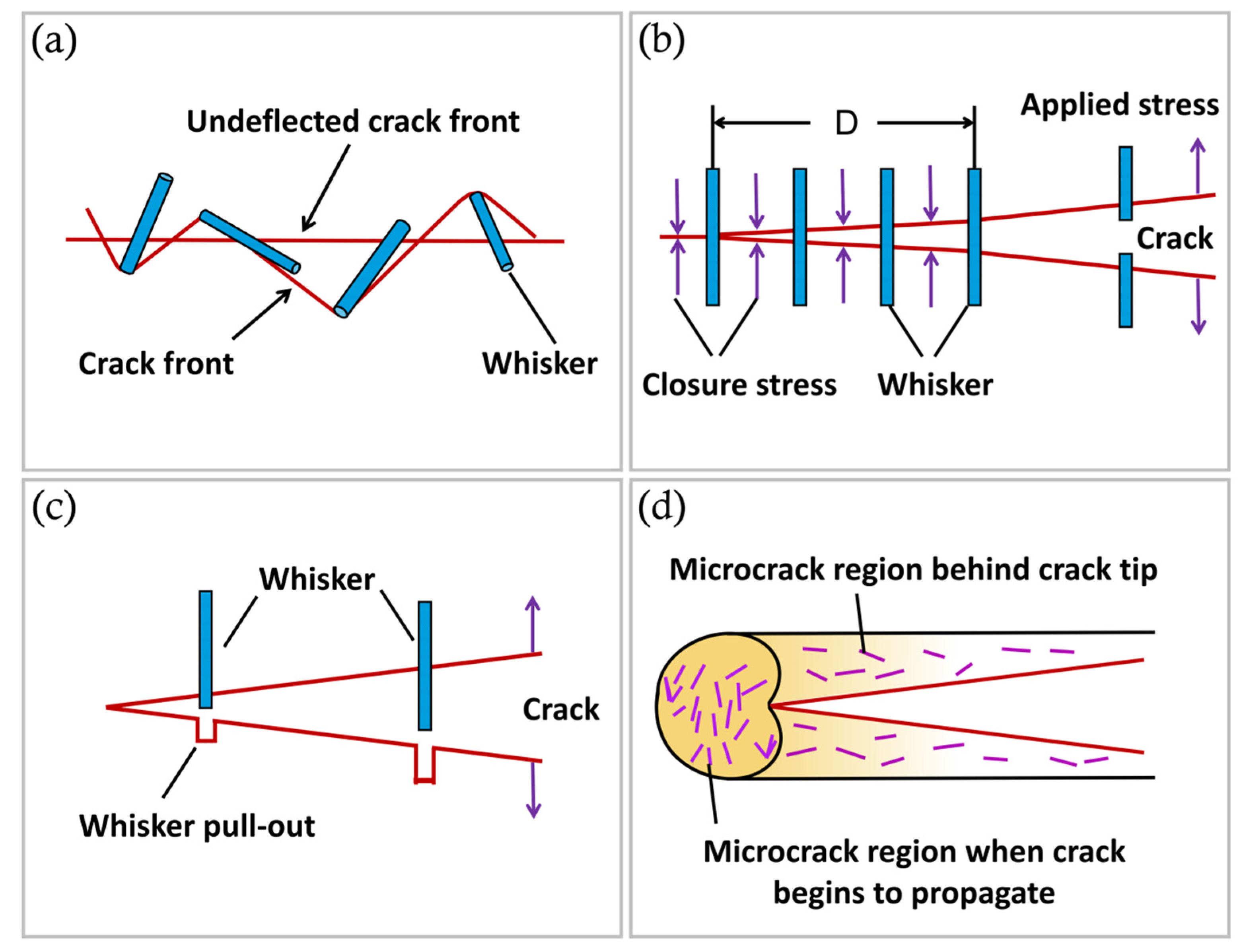
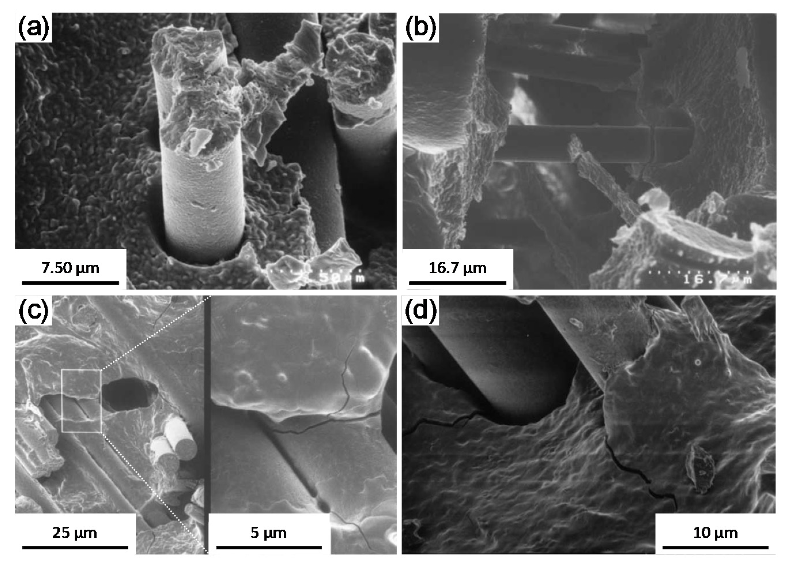
  • Crack deflection: When the crack extends to the whisker, the crack in the substrate is generally difficult to pass through the whisker, and will generally expand by bypassing the whisker, that is the crack deflects. This is mainly due to the high whisker modulus, the existence of the stress field around the whisker. Therefore, more energy needs to be consumed in the process of crack propagation, which makes it difficult for the crack to continue to propagate [114]. As shown in Figure 10a.
  • Crack bridging: When the whiskers in the matrix are distributed in a specific direction, the cracks in the matrix are difficult to deflect and can only continue to propagate according to the original propagation direction. At this time, the whisker close to the crack tip is not broken, which will generate a compressive stress on the crack surface and resist the further propagation of the crack. In other words, whiskers set up small bridges on both sides of the crack to connect the two sides, as shown in Figure 10b.
  • A whisker pull-out region is also present behind that interfacial crack region [115], as shown in Figure 10c, whisker pullout will relax the stress at the crack tip to slow down the crack propagation. The research and analysis show that whisker pullout is often accompanied by crack bridging. When the crack size is small, whisker bridging plays a major role, while with the increase of crack displacement, whiskers at the crack tip are further destroyed, and whisker pullout plays a major toughening mechanism [116].
In addition to the above three main toughening mechanisms, there are also some other mechanisms. Such as microcrack toughening. Under the action of the stress field and residual stress at the crack tip, a microcrack region is formed in front of the crack, as shown in Figure 9d. Whiskers are full of microcracks. The elastic modulus of this region is relatively low and can absorb the energy released by strain, thus passivating the crack tip and terminating the crack propagation. It can also be understood that when the crack tip encounters the whisker, more energy must be applied to make the crack pass through the whisker, but the stress at the crack tip is not enough to break the whisker, thus preventing the crack from spreading, which is similar to pinning [117,118].

6. Toughening Mechanism of Continuous Fibers

The types of continuous fibers reinforcements can be divided into oxide fibers and non-oxide fibers according to different chemical compositions. Such as alumina fibers, aluminosilicate fibers, C fibers, and SiC fibers etc.

6.1. Oxide Fibers

Because the main component of oxide fibers are oxide, oxide fiber has natural oxidation resistance and can be used in oxidizing environment. Alumina fibers and aluminosilicate fibers are commonly used to prepare mullite-based composites [119]. Alumina fibers are mainly composed of Al2O3, and the SiO2 and Al2O3 are that main component of aluminosilicate fibers [120]. The physical properties of some oxide fibers have been summarized, and shown in Table 2 [121,122,123,124].
Alumina fibers are divided into polycrystalline and single crystal alumina fibers according to their crystal structures. Polycrystalline alumina fibers are prone to grain boundary diffusion and grain growth due to the large number of slip surfaces in their crystal structure under load at 1000 °C, which makes the fibers brittle. Volkmann et al. [125] compared the mechanical properties of Nextel TM610/Mullite-SOC composites at 1000 and 1200 °C for 50h. When the service temperature is 1200 °C, the bending strength and fracture toughness decreased significantly compared with 1000 °C. And the bending strength and fracture toughness of the composites decreased by 50% and 38%, respectively. This is mainly due to the increase of grain content in the fiber when the service temperature is 1200 °C. In contrast, single crystal alumina fibers have better creep resistance and are not prone to grain growth under high temperature conditions. However, single crystal alumina fibers are coarser in diameter and difficult to weave, so they are mostly used as unidirectional fiber toughened composites. Pearce et al. [126] prepared a unidirectional single crystal sapphire fiber reinforced mullite matrix composites by pressureless sintering method. When the volume fraction of fiber is 11.5%, the strength of the composites reaches 475 MPa. Kaya et al. [127] carry out cyclic fatigue tests on polycrystalline Al2O3,f/Mullite composite material. After 1.5 × 10⁶ cycles at 1350 °C, the composite still has no fatigue failure, and the maximum stress reaches 357 MPa. The fibers of the fracture surface of the composite material subjected to cyclic fatigue until failure are pulled out as shown in Figure 11a. Figure 11b showing fiber-bridging in a sample subjected to cyclic function. The fiber failure was observed at Figure 11c, which mainly due to the locally strong bonding of the glass phase between the mullite and the alumina fiber. Because there is no close contact between the fiber and the mullite matrix, the growth of the microcrack is cut off, as shown in Figure 11b.
The mechanical properties of mullite can be effectively improved by oxide fibers. However, due to the good chemical compatibility between the fibers and the matrix, the fibers are easy to react with the matrix at high temperature to form strong interfacial bonding. Moreover, the limited temperature resistance of the fiber will also lead to the unsatisfactory strengthening and toughening effect of the fiber. In order to avoid the formation of a strong interface between the fiber and the matrix due to chemical reaction during sintering, the fiber material can be pretreated to change the binding force between the fiber and the matrix [128]. The Boron Nitride (BN) coating with thickness of 1μm was prepared on the surface of NextelTM480 and NextelTM550 fibers by Chawla et al. [129]. The mechanical properties of the coated fiber reinforced mullite composites are greatly improved, the bending strength reaches 258 and 223 MPa, respectively, and the fracture toughness is 8.5 and 6.0 MPa·m1/2, respectively. Liu et al. [130] coated a BN coating on that surface of mullite fiber (Figure 12a) and then prepared the coated fiber-reinforced mullite matrix composite by layer-by-layer assembly method. The damage of fibers can be avoided and the microstructure and mechanical properties of the material can be improved by optimizing the sintering temperature and fiber content. Compared with monolithic mullite ceramics, the toughness of fiber reinforced composites prepared by layer by layer method (LBL) is 5.32 MPa·m1/2, which is about two times that of monolithic mullite ceramics. The micrographs of low/high power cracks of the coated fiber reinforced mullite composite are shown in Figure 12b,c and crack deflection and crack branching can be observed. The fracture morphology of the composite material is shown in Figure 12d, and obvious fiber pullout can be observed.
The main mechanisms of continuous fiber toughening mullite include fiber bridging, crack deflection, fiber fracture, pullout, etc. (Figure 13a). Toughening mechanisms of fiber reinforced composites after coating include crack deflection and crack branch, as shown in Figure 13b. And the toughening mechanisms are summarized as follows:
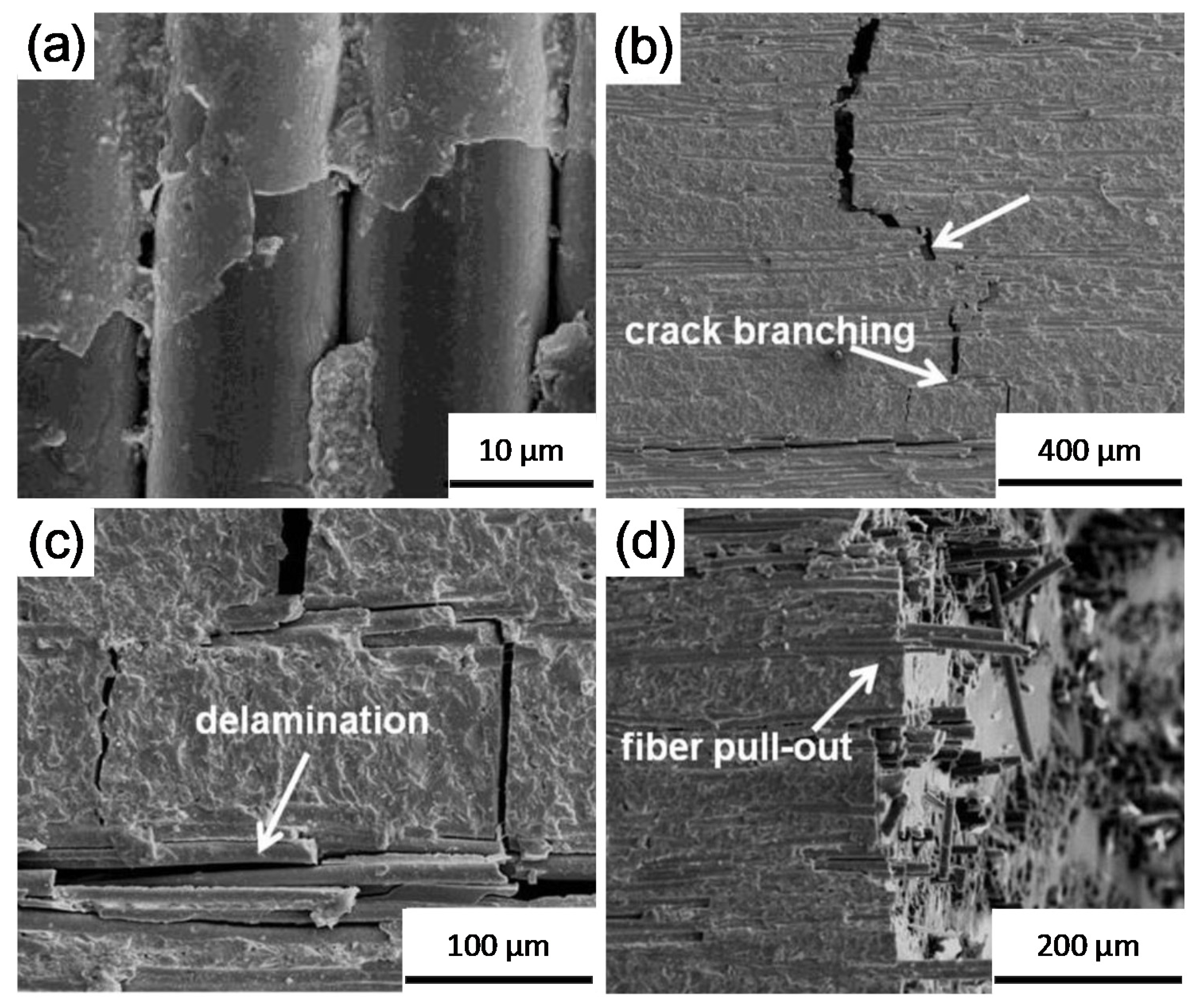
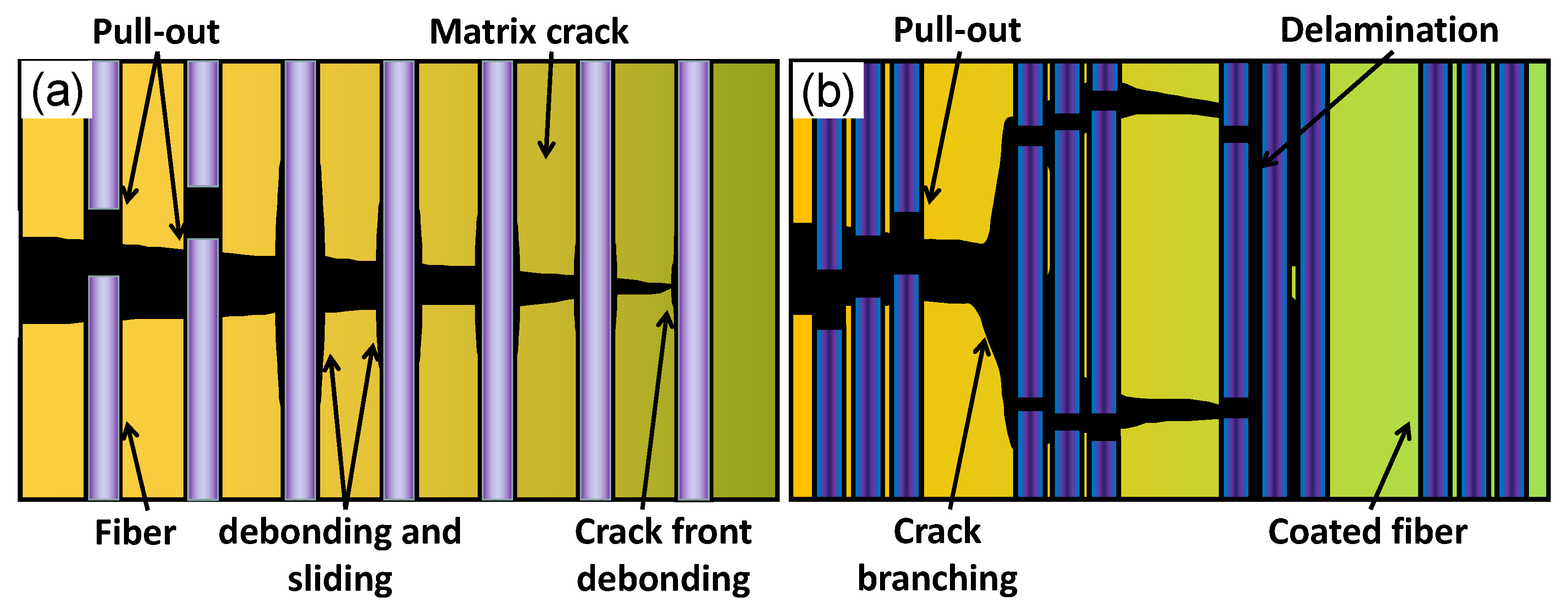
  • The toughening mechanism of fiber reinforced mullite matrix composite includes crack deflection and crack branching, which will release the regionally stress at the tip of crack.
  • The introduction of an interface between the fiber and the matrix can significantly improve the performance of the composite material, weak interface adhesion between the fiber and matrix or fibers resulted in delamination along the smooth interface.
  • Fiber pullout will effectively consume energy and thus play a role in toughening mullite.

6.2. Non-Oxide Fibers

Non-oxide fibers include C fibers, SiC fibers, and so on, which have good high temperature strength, resistance, and rigidity. C fiber has the characteristics of light weight, high specific strength and good chemical stability. The composite material with C fiber as reinforcement has the characteristics stronger than steel and lighter than aluminum, and is one of the most valued high performance materials. Continuous SiC fiber has the characteristics of high specific strength, high specific modulus, high temperature resistance and chemical corrosion resistance, and is called a new material in the field of aviation and aerospace in the 21st century. At present, the main technology of SiC fiber is concentrated in the United States and Japan. According to the performance, SiC fibers of Nicalon 202, Hi-Nicalon and Hi-Nicalon Type-S have been developed respectively [131,132]. Some physical property parameters of C fibers and SiC fibers are listed in Table 3.
One-directional C fibers reinforced and toughened mullite by winding hot press process by Iwata et al. [12] the fracture toughness and flexural strength of the composites, they reached 18 MPa·m1/2 and 600 MPa, respectively, which were greatly improved compared with monomer mullite ceramics. The Cf/Mullite and SiCf/Mullite composites were prepared using the same process as described above by Wu et al. [73] which bending strength and modulus can reach 428–737 MPa and 82–214 GPa, respectively. The material presented non-brittle fracture and the bonding between fiber and interface was relatively weak. Ma et al. [133] prepared 3D-Cf/Mullite composites by dual-phase sol-gel technology. The bending strength and toughness reached 257.9 MPa and 12.2 MPa·m1/2, respectively, and the toughening effect was obvious.
Therefore, non-oxide fiber can obviously improve the mechanical properties of the composite material, especially the fracture toughness, and the effect is better than that of oxide fiber. Moreover, reduction or diffusion reaction is difficult to occur between the fiber and the matrix. The fibers are not easy to oxidize because the presence of mullite matrix protects the fibers, so the composite material can be used at higher temperatures.

7. Conclusions and Prospects

  • The strength of mullite composites reinforced by discontinuous ZrO2 or SiC particles or whiskers has been significantly improved, but the toughness has not been significantly improved. Therefore, the preparation processes of various reinforcement methods need to be studied and improved, such as improving the dispersibility of reinforcements and their bonding ability with matrix, controlling the coarsening of nano-phases, etc. In addition, the forming of complex components, the efficiency and cost of discontinuous enhancement will play an increasingly important role in future research. The theoretical research on the fiber/matrix interface behavior, fiber failure process, and toughened mechanism of continuous fibers under service conditions should be strengthened. And the preparation technology of the materials also should be improved, so as to reduce the damage of fibers in the composites and increase the density of the composites.
  • The main representative of phase transformation toughening is ZrO2. The toughening mechanisms of ZrO2 generally include stress-induced phase transformation toughening, microcrack toughening, zirconia doping toughening, and compression surface toughening. The mechanism of phase transformation toughening has strong temperature sensitivity, so the toughening effect at high temperature is greatly limited, especially the stress-induced phase transformation toughening almost completely fails at high temperature. Therefore, how to expand the effective temperature range of the existing mechanism and seek a new phase change toughening mechanism will be the key to solve the problem of high temperature toughening.
  • The mechanism of toughening mullite with non-phase change second phase particles is mainly the mismatch of the elastic modulus and thermal expansion coefficient between the matrix and particles. The strengthening and toughening mechanism of nano-composite ceramics can be basically summarized as refinement, transgranulation and pinning theories, but a systematic and complete concept has not yet been formed. It is still necessary to conduct in-depth research on the bonding state and stress state of the interface by using fracture mechanics, fracture morphology, numerical analysis, and other methods. The toughening behavior of whisker toughened mullite is affected by many factors, and the main mechanisms include crack bridging, crack deflection, pullout effect, etc. According to the actual conditions, the specific mechanism can be selected, and new composites can be developed by using the excellent properties of whiskers.
  • Continuous fiber reinforced mullite is the main research direction in the near future. The main mechanisms of continuous fiber toughening mullite include fiber bridging, crack deflection, fiber fracture, pullout, etc. The toughening mechanism of coated fiber reinforced mullite composites includes crack deflection, crack branching, fiber delamination and fiber pullout. Improving the service performance of fibers in harsh environment and developing oxide fibers with better heat resistance are the directions of continuous efforts. The performance of the existing system can be effectively improved through interface material selection and design. On this basis, the interface layer connection can be completed through designing an effective and reasonable technological process to realize the expected material function.

Author Contributions

Conceptualization, Y.Z.; methodology, Y.Z. and K.C.; validation, Y.Z. and K.C.; formal analysis, Y.Z. and K.C.; investigation, Y.Z., K.C., and T.F.; resources, Y.Z.; data curation, Y.Z., K.C., and X.Z.; writing—original draft preparation, Y.Z. and K.C.; writing—review and editing, Y.Z. and K.C.; visualization, Y.Z. and J.W.; supervision, Y.Z.; project administration, Y.Z.; funding acquisition, Y.Z. All authors have read and agreed to the published version of the manuscript.

Funding

This research was funded by the National Key R&D Program of China (2017YFB0603800 and 2017YFB0603802); the National Natural Science Foundation (51604049).

Acknowledgments

The authors wish to acknowledge the contributions of associates and colleagues at Anhui University of Technology, Chongqing University. The financial support of the National Key R&D Program of China, and the National Natural Science Foundation.

Conflicts of Interest

The authors declare no conflict of interest.

References

  1. Anggono, J. Mullite Ceramics: Its properties, structure, and synthesis. Jurnal Teknik Mesin 2005, 7, 1–10. [Google Scholar] [CrossRef]
  2. Zhang, G.M.; Wang, Y.C.; Fu, Z.Y.; Wang, H.; Wang, W.M.; Zhang, J.Y.; Lee, S.W.; Niihara, K. Transparent mullite ceramic from single-phase gel by spark plasma sintering. J. Eur. Ceram. Soc. 2009, 29, 2705–2711. [Google Scholar] [CrossRef]
  3. Vargas, F.; Restrepo, E.; Rodríguez, J.E.; Vargas, F.; Arbeláez, L.; Caballero, P.; Arias, J.; López, E.; Latorre, G.; Duarte, G. Solid-state synthesis of mullite from spent catalysts for manufacturing refractory brick coatings. Ceram. Int. 2017, 44, 3556–3562. [Google Scholar] [CrossRef]
  4. Aksay, I.A.; Dabbs, D.M.; Sarikaya, M. Mullite for structural, electronic, and optical applications. J. Am. Ceram. Soc. 1991, 74, 2343–2358. [Google Scholar] [CrossRef]
  5. Tummala, R.R. Ceramic and glass-ceramic packaging in the 1990s. J. Am. Ceram. Soc. 1991, 74, 895–908. [Google Scholar] [CrossRef]
  6. Sprague, J.L. Multilayer ceramic packaging alternatives. IEEE Trans. Compon. Hybrids Manuf. Technol. 1990, 13, 390–396. [Google Scholar] [CrossRef]
  7. Ribero, D.; Restrepo, R.; Paucar, C.; García, C. Highly refractory mullite obtained through the route of hydroxyhydrogels. J Mater Process Technol. 2009, 209, 986–990. [Google Scholar] [CrossRef]
  8. Schneider, H.; Schmücker, M.; Ikeda, K.; Kaysser, W.A. Optically translucent mullite ceramics. J. Am. Ceram. Soc. 1993, 76, 2912–2914. [Google Scholar] [CrossRef]
  9. Sarkar, P.; Datta, S.; Nicholson, P.S. A functionally graded ceramic/ceramic and metal/ceramic composites by electrophoretic deposition. Compos. Part B-Eng. 2003, 28, 49–56. [Google Scholar] [CrossRef]
  10. Takada, H.; Nakahira, A.; Ueda, S.; Niihara, K.; Ohnishi, H. Improvement of mechanical properties of natural mullite/SiC nano-composites. J. Jpn. Soc. 1991, 38, 348–351. [Google Scholar] [CrossRef]
  11. Huang, Z.R. Studyonthe SPS densification of SiC whisker reinforced mullite composites. J. Ceram. 2001, 33, 115–120. (In Chinese) [Google Scholar]
  12. Iwata, M.O.; Shima, K.; Isoda, T. Weak interface dominated high temperature fracture strength of carbon fiber reinforced mullitematrix composites. J. Eur. Ceram. Soc. 2017, 37, 2991–2996. [Google Scholar] [CrossRef]
  13. Schneider, H.; Fischer, R.X.; Schreuer, J. Mullite: Crystal structure and related properties. J. Am. Ceram. Soc. 2015, 98, 2948–2967. [Google Scholar] [CrossRef]
  14. Aryal, S.; Rulis, P.; Ching, W.Y. Mechanical properties and electronic structure of mullite phases using first-principles modeling. J. Am. Ceram. Soc. 2012, 95, 2075–2088. [Google Scholar] [CrossRef]
  15. Schneider, H.; Schreuer, J.; Hildmann, B. Structure and properties of mullite—A review. J. Eur. Ceram. Soc. 2008, 28, 329–344. [Google Scholar] [CrossRef]
  16. Fischer, R.X.; Andrea, G.K.; Birkenstock, J.; Schneider, H. Mullite and mullite-type crystal structures. Int. J. Mater. Res. 2012, 103, 402–407. [Google Scholar] [CrossRef]
  17. Schneider, H.; Fischer, R.X.; Gesing, T.M.; Schreuer, J.; Mühlberg, M. Crystal chemistry and properties of mullite-type Bi2M4O9: An overview. Int. J. Mater. Res. 2012, 103, 422–429. [Google Scholar] [CrossRef]
  18. Fischer, R.X.; Schneider, H.; Voll, D. Formation of aluminum rich 9:1 mullite and its transformation to low alumina mullite upon heating. J. Eur. Ceram. Soc. 1996, 16, 109–113. [Google Scholar] [CrossRef]
  19. Bowen, N.L.; Greig, J.W. The system: Al2O3·SiO2. J. Am. Ceram. Soc. 1924, 7, 238–254. [Google Scholar] [CrossRef]
  20. Johnson, B.R.; Kriven, W.M.; Schneider, J. Crystal structure development during devitrification of quenched mullite. J. Eur. Ceram. Soc. 2001, 21, 2541–2562. [Google Scholar] [CrossRef]
  21. Koyama, T.; Hayashi, S.; Yasumori, A.; Okada, K.; Schmucker, M.; Schneider, H. Microstructure and mechanical properties of mullite/zirconia composites prepared from alumina and zircon under various firing conditions. J. Eur. Ceram. Soc. 1996, 16, 231–237. [Google Scholar] [CrossRef]
  22. Qi, M.Y.; Jia, Q.T.; Zheng, G.J. Preparation and properties of zirconia-toughened mullite ceramics. J. Am. Ceram. Soc. 1986, 69, 265–267. [Google Scholar] [CrossRef]
  23. Zhou, M.; Ferreira, J.; Fonseca, A.T.; Baptista, J.L. In Situ formed alpha-alumina platelets in a mullite-alumina composite. J. Eur. Ceram. Soc. 1998, 18, 495–500. [Google Scholar] [CrossRef]
  24. Schneider, H.; Okada, K. Mullite matrix composites. In Mullite; Schneider, H., Komarneni, S., Eds.; Wiley Online Library: Hoboken, NJ, USA, 2005. [Google Scholar] [CrossRef]
  25. Gustafsson, S.; Falk, L.K.L.; Pitchford, J.E.; Clegg, W.J.; Lidén, E.; Carlstr, M.E. Development of microstructure during creep of polycrystalline mullite and a nanocomposite mullite/5vol.%SiC. J. Eur. Ceram. Soc. 2009, 29, 539–550. [Google Scholar] [CrossRef]
  26. Scribante, A.; Vallittu, P.K.; Özcan, M. Fiber-reinforced composites for dental applications. Biomed Res. Int. 2018, 4, 1–2. [Google Scholar] [CrossRef] [PubMed]
  27. Yao, S.; Zhou, H.; Wu, S.; Kou, M.; Song, B.; Xu, R.; He, R. Microstructure and physical properties of a mullite brick in blast furnace hearth: Influence of temperature. Ironmak. Steelmak. 2020, 3, 1–7. [Google Scholar] [CrossRef]
  28. Chan, C.F.; Ko, Y.C. Effect of Cr2O3 on slag resistance of Al2O3-SiO2 refractories. J. Am. Ceram. Soc. 1992, 75, 2857–2861. [Google Scholar] [CrossRef]
  29. Liu, M.Z.; Zhu, Z.W.; Zhang, Z.; Chu, Y.C.; Yuan, B.; Wei, Z.L. Development of highly porous mullite whisker ceramic membranes for oil-in-water separation and resource utilization of coal gangue. Sep. Purif. Technol. 2020, 237, 1–10. [Google Scholar] [CrossRef]
  30. Zhang, Y.Y.; Li, Y.G.; Bai, C.G. Microstructure and oxidation behavior of Si-MoSi2 functionally graded coating on Mo substrate. Ceram. Int. 2017, 43, 6250–6256. [Google Scholar] [CrossRef]
  31. Zhang, Y.Y.; Qie, J.M.; Cui, K.K.; Fu, T.; Fan, X.L.; Wang, J.; Zhang, X. Effect of hot dip silicon-plating temperature on microstructure characteristics of silicide coating on tungsten substrate. Ceram. Int. 2020, 46, 5223–5228. [Google Scholar] [CrossRef]
  32. Zhang, Y.Y.; Ni, W.J.; Li, Y.G. Effect of siliconizing temperature on microstructure and phase constitution of Mo–MoSi2 functionally graded materials. Ceram. Int. 2018, 44, 11166–11171. [Google Scholar] [CrossRef]
  33. Zhang, Y.Y.; Cui, K.K.; Fu, T.; Wang, J.; Qie, J.M.; Zhang, X. Synthesis WSi2 coating on W substrate by HDS method with various deposition times. Appl. Surf. Sci. 2020, 511, 145551. [Google Scholar] [CrossRef]
  34. Zhang, Y.Y.; Zhao, J.; Li, J.H.; Lei, J.; Cheng, X.K. Effect of hot-dip siliconizing time on phase composition and microstructure of Mo-MoSi2 high temperature structural materials. Ceram. Int. 2019, 45, 5588–5593. [Google Scholar] [CrossRef]
  35. Zhang, Y.Y.; Cui, K.K.; Gao, Q.J.; Hussain, S.; Lv, Y. Investigation of morphology and texture properties of WSi2 coatings on W substrate based on contact-mode AFM and EBSD. Surf. Coat. Technol. 2020, 396, 125966. [Google Scholar] [CrossRef]
  36. Botero, C.A.; Jimenez, E.P.; Martín, R.; Kulkarni, T.; Sarin, V.K.; Llanes, L. Influence of temperature and hot corrosion on the micro–nanomechanical behavior of protective mullite EBCs. Int. J. Refract. Hard. Met. 2015, 49, 383–391. [Google Scholar] [CrossRef]
  37. Lee, K.N.; Fox, D.S.; Eldridge, J.I.; Zhu, D.; Robinson, R.C.; Bansal, N.P. Upper temperature limit of environmental barrier coatings based on mullite and BSAS. J. Am. Ceram. Soc. 2003, 86, 1299–1306. [Google Scholar] [CrossRef] [Green Version]
  38. Aydin, H.; Tokatas, G. Characterization and production of slip casts mullite-zirconia composites. SN Appl. Sci. 2019, 1. [Google Scholar] [CrossRef] [Green Version]
  39. Medvedovski, E. Alumina-mullite ceramics for structural applications. Ceram. Int. 2006, 32, 369–375. [Google Scholar] [CrossRef]
  40. Long, L.; Xiao, P.; Luo, H.; Zhou, W.; Li, Y. Enhanced electromagnetic shielding property of cf/mullite composites fabricated by spark plasma sintering. Ceram. Int. 2019, 45, 18988–18993. [Google Scholar] [CrossRef]
  41. Boccaccini, A.R.; Atiq, S.; Boccaccini, D.N.; Dlouhy, I.; Kaya, C. Fracture behaviour of mullite fibre reinforced-mullite matrix composites under quasi-static and ballistic impact loading. Compos. Sci. Technol. 2005, 65, 325–333. [Google Scholar] [CrossRef]
  42. Kanka, B.; Schneider, H. Aluminosilicate fiber/mullite matrix composites with favorable high-temperature properties. J. Eur. Ceram. Soc. 2000, 20, 619–623. [Google Scholar] [CrossRef]
  43. Zhang, W.; Ma, Q.S.; Dai, K.W.; Mao, W.G. Preparation of three-dimensional braided carbon fiber reinforced mullite composites from a sol with high solid content. Trans. Nonferrous Met. Soc. China 2018, 28, 2248–2254. [Google Scholar] [CrossRef]
  44. Zhang, J.; Wu, H.; Zhang, S.; Yu, J.; Hou, S. Preparation of mullite whiskers and their enhancement effect on ceramic matrix composites. J. WuHan Univ. Technol. 2013, 3, 69–73. [Google Scholar] [CrossRef]
  45. Rangel, E.R.; Sebastián, D.T.; Umemoto, M.; Miyamoto, H.; Heberto, B.R. Zirconia-mullite composites consolidated by spark plasma reaction sintering from zircon and alumina. J. Am. Ceram. Soc. 2005, 88, 1150–1157. [Google Scholar] [CrossRef]
  46. Haldar, M.K. Effect of magnesia additions on the properties of zirconia-mullite composites derived from sillimanite beach sand. Ceram. Int. 2003, 29, 573–581. [Google Scholar] [CrossRef]
  47. Lin, C.C.; Zangvil, A.; Ruh, R. Phase Evolution in silicon carbide-whisker-reinforced mullite/zirconia composite during long-term oxidation at 1000 °C to 1350 °C. J. Am. Ceram. Soc. 2004, 83, 1797–1803. [Google Scholar] [CrossRef] [Green Version]
  48. Gerhardt, R.A.; Ruh, R. Volume fraction and whisker orientation dependence of the electrical properties of SiC-whisker-reinforced mullite composites. J. Am. Ceram. Soc. 2001, 84, 2328–2334. [Google Scholar] [CrossRef]
  49. Zhang, F.C.; Luo, H.H.; Wang, T.S.; Zhang, M.; Sun, Y.N. Stress state and fracture behavior of alumina-mullite intragranular particulate composites. Compos. Sci. Technol. 2008, 68, 3245–3250. [Google Scholar] [CrossRef]
  50. Bodhak, S.; Bose, S.; Bandyopadhyay, A. Densification study and mechanical properties of microwave-sintered mullite and mullite-zirconia composites. J. Am. Ceram. Soc. 2011, 94, 32–41. [Google Scholar] [CrossRef]
  51. Gao, L.; Jin, X.H.; Kawaoka, H.; Sekino, T.; Niihara, K. Microstructure and mechanical properties of SiC-mullite nanocomposite prepared by spark plasma sintering. Mater. Sci. Eng. A 2002, 334, 262–266. [Google Scholar] [CrossRef]
  52. Ghahremani, D.; Ebadzadeh, T.; Maghsodipour, A. Densification, microstructure and mechanical properties of mullite-TiC composites prepared by spark plasma sintering. Ceram. Int. 2015, 41, 1957–1962. [Google Scholar] [CrossRef]
  53. Esharghawi, A.; Penot, C.; Nardou, F. Elaboration of porous mullite-based materials via SHS reaction. Ceram. Int. 2010, 36, 231–239. [Google Scholar] [CrossRef]
  54. Ganesh, I.; Ferreira, J.M.F. Influence of raw material type and of the overall chemical composition on phase formation and sintered microstructure of mullite aggregates. Ceram. Int. 2009, 35, 2007–2015. [Google Scholar] [CrossRef]
  55. Cividanes, L.S.; Campos, T.M.B.; Rodrigues, L.A.; Brunelli, D.D.; Thim, G.P. Review of mullite synthesis routes by sol-gel method. J. Sol-Gel Sci. Technol. 2010, 55, 111–125. [Google Scholar] [CrossRef]
  56. Wang, S.; Shen, X.Q.; Yao, H.C.; Li, Z.J. Synthesis and sintering of pre-mullite powders obtained via carbonate precipitation. Ceram. Int. 2010, 36, 761–766. [Google Scholar] [CrossRef]
  57. Park, H.C.; Yoon, H.C.; Stevens, R. Preparation of zirconia-mullite composites by an infiltration route. Mater. Sci. Eng. A 2005, 405, 233–238. [Google Scholar] [CrossRef]
  58. Roy, J.; Bandyopadhyay, N.; Das, S.; Maitra, S. Role of V2O5 on the formation of chemical mullite from aluminosilicate precursor. Ceram. Int. 2010, 36, 1603–1608. [Google Scholar] [CrossRef]
  59. Mechnich, P.; Schneider, H. Reaction bonding of mullite (RBM) in presence of scandia Sc2O3. J. Eur. Ceram. Soc. 2008, 28, 473–478. [Google Scholar] [CrossRef]
  60. Sacks, M.D.; Bozkurt, N.; Scheiffele, G.W. Fabrication of mullite and mullite-matrix composites by transient viscous sintering of composite powders. J. Am. Ceram. Soc. 1991, 74, 2428–2437. [Google Scholar] [CrossRef]
  61. Chen, Z.; Zhang, L.; Cheng, L.; Xiao, P.; Duo, G.B. Novel method of adding seeds for preparation of mullite. J. Mater. Process. Technol. 2005, 166, 183–187. [Google Scholar] [CrossRef]
  62. Griggio, F.; Bernardo, E. Kinetic studies of mullite synthesis from alumina nanoparticles and a preceramic polymer. J. Am. Ceram. Soc. 2008, 91, 2529–2533. [Google Scholar] [CrossRef]
  63. Huang, Z.; Shen, Z.; Lin, L.; Nygren, M.; Jiang, D. Spark-plasma-sintering consolidation of sic-whisker-reinforced mullite composites. J. Am. Ceram. Soc. 2004, 81, 42–46. [Google Scholar] [CrossRef]
  64. Bin, M.; Hui, P.J. Optimization on influencing factors of fracture toughness of corundum-mullite toughened by in situ synthesized mullite whiskers by response surface methodology. Adv. Mat. Res. 2012, 581, 819–822. [Google Scholar] [CrossRef]
  65. Yi, P.; Zhao, P.D.; Zhang, D.Q.; Zhang, H.; Zhao, H.Z. Preparation and characterization of mullite microspheres based porous ceramics with enhancement of in-situ mullite whiskers. Ceram. Int. 2019, 45, 14517–14523. [Google Scholar] [CrossRef]
  66. Dey, A.; Chatterjeeet, M.L.; Naskar, M.; Basu, K. Near-net-shape fibre-reinforced ceramic matrix composites by the sol infiltration technique. Mater. Lett. 2003, 57, 2919–2926. [Google Scholar] [CrossRef]
  67. Boccaccini, A.R.; Kaya, C. Use of electrophoretic deposition in the processing of fibre reinforced ceramic and glass matrix composites: A review. Compos. Part. A-Appl. Sci. Manuf. 2001, 32, 997–1006. [Google Scholar] [CrossRef]
  68. Garshin, A.P.; Kulik, V.I.; Matveev, S.A.; Nilov, A.S. Contemporary technology for preparing fiber-reinforced composite materials with a ceramic refractory matrix (review). Refract. Ind. Ceram. 2017, 58, 148–161. [Google Scholar] [CrossRef]
  69. Yang, J.Y.; Weaver, J.H.; Zok, F.W.; Mack, J.J. Processing of oxide composites with three-dimensional fiber architectures. J. Am. Ceram. Soc. 2009, 92, 1087–1092. [Google Scholar] [CrossRef]
  70. Holmquist, M.G.; Radsick, T.C.; Sudre, O.H.; Lange, F.F. Fabrication and testing of all-oxide CFCC tubes. Compos. Part. A-Appl. Sci. Manuf. 2003, 34, 163–170. [Google Scholar] [CrossRef]
  71. Holmquist, M.G.; Lange, F.F. Processing and properties of a porous oxide matrix composite reinforced with continuous oxide fibers. J. Am. Ceram. Soc. 2003, 86, 1733–1740. [Google Scholar] [CrossRef]
  72. Gerardin, C.; Sundaresan, S.; Benziger, J.; Navrotsky, A. Structural investigation and energetics of mullite formation from sol-gel precursors. Chem. Mater. 1994, 6, 160–170. [Google Scholar] [CrossRef]
  73. Zeng, K.H.; Li, Z.Q.; Liang, S.L.; Lv, X.; Ma, Q.S. Thermal properties of carbon fiber reinforced mullite composites derived from sol-gel. Key Eng. Mater. 2017, 727, 461–465. [Google Scholar] [CrossRef]
  74. Wu, J.; Jones, F.; James, P. Continuous fibre reinforced mullite matrix composites by sol-gel processing: Part I Fabrication and microstructures. J. Mater. Sci. 1997, 32, 3361–3368. [Google Scholar] [CrossRef]
  75. Wu, J.; Jones, F.; James, P. Continuous fibre reinforced mullite matrix composites by sol-gel processing: Part II properties and fracture behaviour. J. Mater. Sci. 1997, 32, 3629–3635. [Google Scholar] [CrossRef]
  76. Dong, R.; Hirata, Y.; Sueyoshi, H.; Higo, M.; Uemura, Y. Polymer impregnation and pyrolysis (PIP) method for the preparation of laminated woven fabric/mullite matrix composites with pseudoductility. J. Eur. Ceram. Soc. 2004, 24, 53–64. [Google Scholar] [CrossRef]
  77. Chen, Z.F.; Tao, J.; Liu, Z.L.; Pan, L.; Dai, Y. Mullite ceramic composites fabricated by chemical vapor infiltration. J. Nanjing Univ. Aeronaut. Astronaut. 2005, 37, 562–566. [Google Scholar] [CrossRef]
  78. Leuchs, M. Matrix composites: CVI (chemical vapor infiltration). In Wiley Encyclopedia of Composites; Nicolais, L., Ed.; Wiley Online Library: Hoboken, NJ, USA, 2011. [Google Scholar] [CrossRef]
  79. Ashizuka, M.; Honda, T.; Kubota, Y. Creep in mullite ceramics containing zirconia. J. Ceram. Soc. Jpn. 1991, 99, 357–360. [Google Scholar] [CrossRef] [Green Version]
  80. Lin, C.C.; Zangvil, A.; Ruh, R. Modes of oxidation in SiC-reinforced mullite/ZrO2 composites: Oxidation vs. depth behavior. Acta Mater. 1999, 47, 1977–1986. [Google Scholar] [CrossRef]
  81. Rendtorff, N.; Garrido, L.; Aglietti, E. Mullite-zirconia-zircon composites: Properties and thermal shock resistance. Ceram. Int. 2009, 35, 779–786. [Google Scholar] [CrossRef]
  82. Ruh, R.; Mazdiyasni, K.S.; Mendiratta, M.G. Mechanical and microstructural characterization of mullite and mullite-SiC-whisker and ZrO2-toughened-mullite-SiC-whisker composites. J. Am. Ceram. Soc. 1988, 71, 503–512. [Google Scholar] [CrossRef]
  83. Nakonieczny, D.S.; Antonowicz, M.; Paszenda, Z.K.; Radko, T.; Drewniak, S.; Bogacz, W.; Krawczyk, C. Experimental investigation of particle size distribution and morphology of alumina-yttria-ceria-zirconia powders obtained via sol-gel route. Biocybern. Biomed. Eng. 2018, 38, 535–543. [Google Scholar] [CrossRef]
  84. Nakonieczny, D.S.; Ziębowicz, A.; Paszenda, Z.K.; Krawczyk, C. Trends and perspectives in modification of zirconium oxide for a dental prosthetic applications—A review. Biocybern. Biomed. Eng. 2017, 37, 229–245. [Google Scholar] [CrossRef]
  85. Claussen, N.; Jahn, J. Mechanical properties of sintered, in situ-reacted mullite-zirconia composites. J. Am. Ceram. Soc. 1980, 64, 228–229. [Google Scholar] [CrossRef]
  86. Chu, M.C.; Sato, S.; Kobayashi, Y.; Ando, K. Strengthening of mullite by dispersion of carbide ceramics particles. JSME Int. J. 1996, 39, 259–265. [Google Scholar] [CrossRef]
  87. Zhong, H.L.; Yong, Z.; Schmauder, S. Transformation, microcrack, and thermal residual stress as interactive processes in ZrO2-Toughened Al2O3, Simulated by the finite element method. Metall. Mater. Trans. A 1994, 25, 1725–1731. [Google Scholar] [CrossRef]
  88. Hannink, R. Transformation toughening in zirconia-containing ceramics. J. Am. Ceram. Soc. 2000, 83, 461–487. [Google Scholar] [CrossRef]
  89. Shin, Y.S.; Rhee, Y.W.; Kang, S.L. Experimental evaluation of toughening mechanisms in alumina-zirconia composites. J. Am. Ceram. Soc. 1999, 82, 1229–1232. [Google Scholar] [CrossRef]
  90. Guan, S.H.; Zhang, X.J.; Liu, Z.P. Energy landscape of zirconia phase transitions. J. Am. Ceram. Soc. 2015, 137, 8010–8013. [Google Scholar] [CrossRef]
  91. Rühle, M.; Claussen, N.; Heuer, A.H. Transformation and microcrack toughening as complementary processes in ZrO2-toughened Al2O3. J. Am. Ceram. Soc. 1986, 69, 195–197. [Google Scholar] [CrossRef]
  92. Rühle, M. Microcrack and transformation toughening of zirconia-containing alumina. Mater. Sci. Eng. A 105- 1988, 106, 77–82. [Google Scholar] [CrossRef]
  93. Chu, M.C.; Sato, S.; Kobayashi, Y.; Ando, K. Damage healing and strengthening behaviour in intellignt mullite/SiC ceramicsFatigue. Fract. Eng. Mater. Struct. 1995, 18, 1019–1029. [Google Scholar] [CrossRef]
  94. Akpinar, S.; Kusoglu, I.M.; Ertugrul, O.; Onel, K. Silicon carbide particle reinforced mullite composite foams. Ceram. Int. 2012, 38, 6163–6169. [Google Scholar] [CrossRef]
  95. Aramide, F.O. Effects of silicon carbide on the phase developments in mullite-carbon ceramic composite. Leonardo J. Pract. Technol. 2017, 31, 45–58. [Google Scholar] [CrossRef]
  96. Ding, S.Q.; Zhu, S.M.; Zeng, Y.P.; Jiang, D.L. Fabrication of mullite-bonded porous silicon carbide ceramics by in situ reaction bonding. J. Eur. Ceram. Soc. 2007, 27, 2095–2102. [Google Scholar] [CrossRef]
  97. Taya, M.; Hayashi, S.; Kobayashi, A.; Yoon, H.S. Toughening of a particulate-reinforced ceramic-matrix composite by thermal residual stress. J. Am. Ceram. Soc. 1990, 73, 1382–1391. [Google Scholar] [CrossRef]
  98. Koichi, N. New design concept of structural ceramics. J. Ceram. Soc. Japan 1991, 99, 974–982. [Google Scholar] [CrossRef] [Green Version]
  99. Tjong, S.C. Novel nanoparticle-reinforced metal matrix composites with enhanced mechanical properties. Adv. Eng. Mater. 2007, 9, 639–652. [Google Scholar] [CrossRef]
  100. Yoshimura, M.; Tatsuki, O.; Mutsuo, S.; Choa, Y.H.; Sekino, T.; Niihara, K. Oxidation-induced strengthening and toughening behavior in micro- and nano-composites of Y2O3/SiC system. Mater. Lett. 1998, 35, 139–143. [Google Scholar] [CrossRef]
  101. Elyas, H.; Kim, T.W.; Jang, B.K.; Lee, K.S. Damage and wear resistance of Al2O3-SiC microcomposites with hard and elastic properties. J. Ceram. Soc. Japan 2018, 126, 21–26. [Google Scholar] [CrossRef] [Green Version]
  102. Gao, L.; Wang, H.Z.; Hong, J.S.; Miyamoto, H.; Miyamoto, K.; Nishikawa, Y.; Díaz, S. Mechanical properties and microstructure of nano-SiC-Al2O3 composites densified by spark plasma sintering. J. Eur. Ceram. Soc. 1999, 19, 609–613. [Google Scholar] [CrossRef]
  103. Deng, Z.Y.; Shi, J.L.; Zhang, Y.F.; Jiang, D.Y.; Guo, J.K. Pinning effect of SiC particles on mechanical properties of Al2O3-SiC ceramic matrix composites. J. Eur. Ceram. Soc. 1998, 18, 501–508. [Google Scholar] [CrossRef]
  104. Li, S.; Zhang, Y.M.; Han, J.C.; Zhou, Y.F. Fabrication and characterization of SiC whisker reinforced reaction bonded SiC composite. Ceram. Int. 2013, 39, 449–455. [Google Scholar] [CrossRef]
  105. Luo, Y.; Zheng, S.L. Mullite-bonded SiC-whisker-reinforced SiC matrix composites: Preparation, characterization, and toughening mechanisms. J. Eur. Ceram. Soc. 2018, 38, 5282–5293. [Google Scholar] [CrossRef]
  106. Zou, L.H.; Huang, Y.; Park, D.S.; Cho, B.U.; Kim, H.; Hahn, B.D. R-curve behavior of Si3N4 whisker-reinforced Si3N4 matrix composites. Ceram. Int. 2005, 31, 197–204. [Google Scholar] [CrossRef]
  107. Zhang, C.; Zeng, Y.P.; Yao, D.; Yin, J.; Zuo, K.; Xia, Y. The improved mechanical properties of Al matrix composites reinforced with oriented β-Si3N4 whisker. J. Mater. Sci. Technol. 2019, 35, 1345–1353. [Google Scholar] [CrossRef]
  108. Wang, M.C.; Liu, J.C.; Du, H.Y.; Guo, A.; Tao, X.; Dong, X.; Geng, H. A SiC whisker reinforced high-temperature resistant phosphate adhesive for bonding carbon/carbon composites. J. Alloy. Compd. 2015, 633, 145–152. [Google Scholar] [CrossRef]
  109. Zhou, L.; Fu, Q.G.; Huo, C.X.; Tong, M.D.; Liu, X.S.; Hu, D. Mullite whisker-mullite/yttrium aluminosilicate oxidation protective coatings for SiC coated C/C composites. Ceram. Int. 2019, 45, 24022–24030. [Google Scholar] [CrossRef]
  110. Lv, X.Y.; Ye, F.; Cheng, L.F.; Fan, S.W.; Liu, Y.S. Fabrication of SiC whisker-reinforced SiC ceramic matrix composites based on 3D printing and chemical vapor infiltration technology. J. Eur. Ceram. Soc. 2019, 39, 3380–3386. [Google Scholar] [CrossRef]
  111. Wang, Q.B.; Guo, M.Y. Synthesis of SiC whisker and its application in composite materials. Int. J. Coal Sci. Technol. 1997, 3, 49–53. [Google Scholar] [CrossRef]
  112. Tamari, N.; Kondok, I.; Tanaka, T. Mechanical properties of alumina whisker/mullite composite ceramics. J. Ceram. Soc. Japan 1995, 103, 199–201. [Google Scholar] [CrossRef] [Green Version]
  113. Hirata, Y.; Matsushita, S.C.; Ishihara, Y.; Katsuki, H. Colloidal processing and mechanical properties of whisker-reinforced mullite matrix composites. J. Am. Ceram. Soc. 1991, 74, 2438–2442. [Google Scholar] [CrossRef]
  114. Rödel, J. Interaction between crack deflection and crack bridging. J. Eur. Ceram. Soc. 1992, 10, 143–150. [Google Scholar] [CrossRef]
  115. Fan, B.; Zhu, S.G.; Ding, H.; Bai, Y.F.; Luo, Y.L.; Di, P. Influence of MgO whisker addition on microstructures and mechanical properties of WC-MgO composite. Mater. Chem. Phys. 2019, 238, 11–17. [Google Scholar] [CrossRef]
  116. Lairdii, G.; Kennedy, T.C. Crack wake toughening mechanisms in a whisker-reinforced ceramic. Finite Elem. Anal. Des. 1991, 9, 113–124. [Google Scholar] [CrossRef]
  117. Paul, F.B.; Hsueh, C.H.; Angelini, P.; Tiegs, T.N. Toughening behavior in whisker-reinforced ceramic matrix composites. J. Am. Ceram. Soc. 1988, 71, 1050–1061. [Google Scholar] [CrossRef]
  118. Dolgopolsky, A.; Karbhari, V.; Kwak, S.S. Microcrack induced toughening-an interaction model. Acta Metall. 1989, 37, 1349–1354. [Google Scholar] [CrossRef]
  119. Radsick, T.; Saruhan, B.; Schneider, H. Damage tolerant oxide/oxide fiber laminate composites. J. Eur. Ceram. Soc. 2000, 20, 545–550. [Google Scholar] [CrossRef]
  120. Kriven, W.M.; Palko, J.W.; Sinogeikin, S.V.; Bass, J.; Sayir, A.; Brunauer, G.; Boysen, H.; Frey, F.; Schneider, J. High Temperature single crystal properties of mullite. J. Eur. Ceram. Soc. 1999, 19, 2529–2541. [Google Scholar] [CrossRef]
  121. Chawla, K.K.; Coffin, C.; Xu, Z.R. Interface engineering in oxide fibre/oxide matrix composites. Int. Mater. Rev. 2000, 45, 165–189. [Google Scholar] [CrossRef]
  122. Kaufmann, H.; Mortensen, A. Wetting of SAFFIL alumina fiber preforms by aluminum at 973 K. Metall. Mater. Trans. A 1992, 23, 2071–2073. [Google Scholar] [CrossRef]
  123. Hay, R.S.; Fair, G.E.; Tidball, T. Fiber strength after grain growth in nextel 610 alumina fiber. J. Am. Ceram. Soc. 2015, 98, 1907–1914. [Google Scholar] [CrossRef]
  124. Schawaller, D.; Clau, B.; Buchmeiser, M.R. Ceramic filament fibers—A review. Macromol. Mater. Eng. 2012, 297, 502–522. [Google Scholar] [CrossRef]
  125. Volkmann, E.; Evangelista, L.L.; Tushtev, K.; Koch, D.; Wilhelmi, C.; Rezwan, K. Oxidation-induced microstructural changes of a polymer-derived nextelâ, ¢ 610 ceramic composite and impact on the mechanical performance. J. Mater. Sci. 2014, 49, 710–719. [Google Scholar] [CrossRef]
  126. Pearce, D.H.; Rusch, J.J.; Boccaccini, A.R.; Ponton, C.B.; Rohr, L. Characterisation of a pressureless sintered sapphire fibre reinforced mullite matrix composite. Mater. Sci. Eng. A 1996, 214, 170–173. [Google Scholar] [CrossRef]
  127. Kaya, C.; Kaya, F.; Mori, H. Damage assessment of alumina fibre-reinforced mullite ceramic matrix composites subjected to cyclic fatigue at ambient and elevated temperatures. J. Eur. Ceram. Soc. 2002, 22, 447–452. [Google Scholar] [CrossRef]
  128. Hinoki, T.; Yang, W.; Nozawa, T.; Shibayama, T.; Katoh, Y.; Kohyama, A. Improvement of mechanical properties of sic/sic composites by various surface treatments of fibers. J. Nucl. Mater. 2001, 289, 23–29. [Google Scholar] [CrossRef]
  129. Chawla, K.K.; Xu, Z.R.; Ha, J.S. Processing, structure, and properties of mullite fiber/mullite matrix composites. J. Eur. Ceram. Soc. 1996, 16, 293–299. [Google Scholar] [CrossRef]
  130. Liu, D.Z.; Hu, P.; Fang, C.; Han, W.B. Fabrication of unidirectional continuous fiber-reinforced mullite matrix composite with excellent mechanical property. Ceram. Int. 2018, 44, 13487–13494. [Google Scholar] [CrossRef]
  131. Wang, P.R.; Liu, F.Q.; Wang, H.; Li, H.; Guo, Y.Z. A review of third generation SiC fibers and SiCf/SiC composites. J. Mater. Sci. Technol. 2019, 35, 2743–2750. [Google Scholar] [CrossRef]
  132. Ishikawa, T. Recent developments of the SiC fiber nicalon and its composites, including properties of the SiC fiber Hi-Nicalon for ultra-high temperature. Compos. Sci. Technol. 1994, 51, 135–144. [Google Scholar] [CrossRef]
  133. Ma, Q.S.; Chen, Z.H.; Zheng, W.W.; Hu, H.F. Fabrication and mechanical properties of three-dimensional carbon fibre reinforced mullite composites via sol-gel. RMMAE 2004, 33, 111–114. (In Chinese) [Google Scholar]
Figure 1. Crystal structure of mullite in comparison to that of sillimanite in projections parallel [0 0 1] (above) and parallel [1 0 0] (below).
Coatings 10 00672 g001
Figure 2. Effect of ZrO2,P and SiCW on bending strength (a) and fracture toughness (b) of mullite.
Coatings 10 00672 g002
Figure 3. Large size and high purity single crystal mullite (a) and typical microstructure of sintered mullite materials (b).
Coatings 10 00672 g003
Figure 4. The industrial application prospect of typical mullite matrix composites: (a) Mullite multilayer ceramic package; (b) Optically translucent mullite; (c) Panel for a re-entry space vehicle (mullite-coated C/C-SiC composite); (d) ZrO2/Mullite refractories for glass industry kilns; (e) Ballistic armor plate; and (f) Thermal protection materials for combustors and aircraft gas turbine engines.
Coatings 10 00672 g004
Figure 5. Schematic representation of the three polymorphs of ZrO2 and the corresponding space groups: (a) cubic; (b) tetragonal; and (c) monoclinic.
Coatings 10 00672 g005
Figure 6. SEM images of ZrO2 reinforced mullite composites (a,b).
Coatings 10 00672 g006
Figure 7. Toughening mechanism of ZrO2 particles for mullite ceramic: (a) Stress-induced toughening; (b) Microcrack toughening; (c) ZrO2 incorporation toughening; and (d) Surface compression toughening.
Coatings 10 00672 g007
Figure 8. SEM and TEM images of SiC reinforced mullite composites: (a) SEM image; (b) Dislocations pinned by intragranular cavities; (c) SiC particles (P); (d) SiC particles present in both inter-and intragranular positions; and (e) Intergranular SiC Particles.
Coatings 10 00672 g008
Figure 9. Schematic diagram of toughening mechanism of Nanoparticles: (a) Intra-type; (b) Inter-type; (c) Intra/Inter-type; and (d) Nano/nano-type.
Coatings 10 00672 g009
Figure 10. Schematic diagram of toughening mechanism of whiskers: (a) Mechanism of crack deflection; (b) Mechanism of crack bridge link; (c) Scheme of whisker pullout mechanism; and (d) Mechanism of microcrack propagation.
Coatings 10 00672 g010
Figure 11. (a) Pullout of fibers on the fracture surface of the sample subjected to cyclic fatigue until failure; (b) Fiber-bridging of the matrix; (c) Fiber breakage; and (d) Microcracks in that matrix are arrested.
Coatings 10 00672 g011
Figure 12. Mullite fiber surface is coated with BN coating (a); Micrographs of cracks (b); High power micrographs of cracks (c); and Fracture of composite material (d).
Coatings 10 00672 g012
Figure 13. Toughening mechanism diagram of fiber reinforced mullite matrix composites (a) and Schematic diagram of toughening mechanism of coated fiber reinforced mullite composites (b).
Coatings 10 00672 g013
Table 1. Thermo-mechanical properties of mullite ceramics and other advanced oxide ceramics.
CompoundTieilliteCordieriteSpinelα-AluminaZirconiaMullite
CompositionAl2O3·TiO22MgO·2Al2O3·5SiO2MgO·
Al2O3
Al2O3ZrO23Al2O3·
2SiO2
Melting Point (℃)18601465213520502600≈1830
Density (g cm–3)3.682.23.653.965.60≈3.2
Linear Thermal Expansion (× 10–6·°C–1)
20–1400 ℃
≈1≈09810≈4.5
Thermal Conductivity (kcal·m−1·h–1·°C–1)
20–1400 °C
1.5–22.5≈10–51342641.5263
Strength (MPa)30120180500200≈200
Fracture Toughness KIC (MPa·m1/2)≈1.5≈4.5≈2.4≈2
Table 2. Properties of some oxide fibers.
Producer
Fiber
Composition
(wt.%)
Diameter
(μm)
Density
(g·cm–3)
Tensile Strength
/Modulus (GPa/GPa)
Structure
Dupont
FP
Al2O3:100203.9>1.40/380–400α-Al2O3
Saphikon
Sapphire
Al2O3:10075–2254.02.10–3.40/414α-Al2O3
3M
Nextel 610
Al2O3:100
Fe2O3:0.7
SiO2:0.3
10–123.93.10/380α-Al2O3
3M
Nextel 720
Al2O3:85
SiO2:15
10–123.42.10/260Mullite+α-Al2O3
3M
Nextel 550
Al2O3:73
SiO2:27
10–123.032.0/193γ-Al2O3+α-SiO2
3M
Nextel 440
Al2O3:70
SiO2:28
B2O3:2
10–123.052.0/190Mullite+γ-Al2O3+
α-SiO2
Dupont
PRD-166
Al2O3:80
ZrO2:20
194.22.07/380α-Al2O3+
w/o zirconia
Nitivy
Nitivy ALF
Al2O3:70
SiO2:28
B2O3:2
103.01.75/190γ-Al2O3+α-SiO2
Table 3. Partial physical property parameters of C and SiC fibers.
BrandCSiC
T300T800T1000Nicalon 202Hi-NicalonHi-NicalonType-S
Density (g·cm−3)1.771.811.822.552.743.05
Fiber diameter (μm)7.05.25.3141212
Tensile strength (GPa)3.535.597.0632.82.5
Tensile modulus (GPa)230294294185400400
Fracture strain (%)1.51.92.410.60.6

