Article

Glancing Angle Deposition and Growth Mechanism of Inclined AlN Nanostructures Using Reactive Magnetron Sputtering

Thin Film Physics Division, Department of Physics, Chemistry and Biology (IFM), Linköping University, SE-581 83 Linköping, Sweden
*
Author to whom correspondence should be addressed.
Coatings 2020, 10(8), 768; https://doi.org/10.3390/coatings10080768
Submission received: 1 July 2020 / Revised: 4 August 2020 / Accepted: 6 August 2020 / Published: 7 August 2020
(This article belongs to the Special Issue Physical Vapor Deposition)

Abstract

:
Glancing angle deposition (GLAD) of AlN nanostructures was performed at room temperature by reactive magnetron sputtering in a mixed gas atmosphere of Ar and N2. The growth behavior of nanostructures shows strong dependence on the total working pressure and angle of incoming flux. In GLAD configuration, the morphology changed from coalesced, vertical nanocolumns with faceted terminations to highly inclined, fan-like, layered nanostructures (up to 38°); while column lengths decreased from around 1743 to 1068 nm with decreasing pressure from 10 to 1.5 mTorr, respectively. This indicates a change in the dominant growth mechanism from ambient flux dependent deposition to directional ballistic shadowing deposition with decreasing working pressures, which is associated with the change of energy and incident angle of incoming reactive species. These results were corroborated using simulation of metal transport (SiMTra) simulations performed at similar working pressures using Ar and N separately, which showed the average particle energy and average angle of incidence decreased while the total average scattering angle of the metal flux arriving at substrate increased with increasing working pressures. Observing the crystalline orientation of GLAD deposited wurtzite AlN nanocolumns using X-ray diffraction (XRD), pole-figure measurements revealed c-axis <0001> growth towards the direction of incoming flux and a transition from fiber-like to biaxial texture took place with increasing working pressures. Under normal deposition conditions, AlN layer morphology changed from {0001} to {10 1 ¯ 1} with increasing working pressure because of kinetic energy-driven growth.

1. Introduction

Understanding the growth of nanoscale materials and thin films from the vapor phase is of fundamental importance to realize practical applications. Although simple geometries of nanomaterials have their place in materials research, advancements in growth technology have demonstrated the importance of thin films and anisotropic nanostructures and the crucial correlation to their morphology [1,2,3] and crystal structure [4,5,6,7]. Thin films have found utility in practically endless applications, such as electrical insulators [8], hard coatings [9], photovoltaics [10] and piezoelectric devices [11], just to name a few, with the earliest documented use being as early as ~2600 BC [12]. Structured/sculptured thin films in particular first emerged around 1996 [13], soon finding utility in optics [14], biomedicine [15], hydrophobic coatings [16], solar cells [17], etc. There are abundant ways to grow thin films such as metal organic chemical vapor deposition (MOCVD), molecular beam epitaxy (MBE), electron cyclotron resonance dual-ion beam sputtering, and pulsed laser ablation. However, they are expensive processes requiring high process temperatures, motivating the selection of the physical vapor deposition (PVD) route, like direct current (DC) magnetron sputtering, with prospects of improved film quality and versatility in terms of process parameters such as non-equilibrium low temperature growth. Also, films deposited using a line of sight configuration in PVD usually exhibit columnar morphologies thereby offering the opportunity to incorporate glancing angle deposition (GLAD) for sculptured thin films [18,19,20]. GLAD is a development from the oblique angle deposition technique (OAD), which has been widely used to grow complex nanostructures by manipulating the substrate and/or source orientation during the deposition process. Here, the trajectory of incident flux to the substrate (angle of incidence, α) is directed to be almost perpendicular to the substrate normal (α > 70°). This results in films with anisotropic physical properties such as a tilted columnar morphology. Adding substrate rotation (rotation angle, φ) results in another degree of freedom and the technique is termed GLAD, see Figure 1a [21,22,23]. As a result, films with complex architectures such as chevrons, nanospirals, inclined columns and branched nanocolumns have been grown [14,24,25,26,27,28,29,30] for applications such as optical sensors, pressure sensors, field emitters, gas sensors, photonics, wettability, and biocompatibility [31,32,33,34,35,36,37,38].
Films deposited using the GLAD technique tend to follow the Volmer–Weber growth mode [39], where the adatoms are more reactive with each other than with the substrate, and results in the formation of three-dimensional islands owing to higher adatom—adatom interaction. Generally, nucleation sets the course for the structural evolution of deposited films [40,41]. For amorphous substrates and deposition at low temperatures, the initial nucleation stage is usually random in nature. However, subsequent growth is a competitive process and has a preferred orientation due to the GLAD configuration. Thanks to this oblique growth configuration, the region behind the nucleus is shadowed and incoming atoms deposit on the exposed surface of the nuclei aligned towards the source of incoming flux [22]. This line-of-sight deposition is termed “ballistic shadowing” and results in tilted, separate columns of different heights oriented towards the source with an angle β from the substrate’s normal (illustrated in Figure 1b). Experimentally, β is not equal to α and is highly dependent on the choice of materials and deposition method. Several models have been proposed to explain this relationship: universal models such as the empirical tangent rule proposed by Nieuwenhuizen et al. [42] and ballistic cosine rule by Tait et al. [43] are the most popular, where the former works for smaller values of α and the latter fits experimental data better for α > 70°. Another ballistic simulations-based approach was proposed by Meakin et al. [44] in an attempt to fit the whole range of α with β using two linear functions separated by an intermediate transition zone, while Lichter et al. [45] proposed a continuum approach using an input parameter that depends on surface diffusion. Tanto et al. [46] proposed a semi-empirical model to relate α and β using a parameter called “fan angle”, summarizing deposition and material properties into this single parameter. Thus, the α–β relationship has been a topic of widespread discussion owing to discrepancies between the geometric considerations used to describe the empirical model and different material types and/or growth conditions [47,48].
Elucidation of such column and flux inclinations from substrate normal became imperative after some early reports demonstrated birefringent and dichromatic properties of deposited films as a direct result of film morphology [21,22]. This morphology was achieved by manipulating substrate rotation while impinging flux arrived at the substrate from an oblique angle resulting in a thin film composed of nanospirals. Local birefringence arising due to this chiral morphology represents a twisted biaxial media, and such structures have found utility as Bragg reflectors, filters, and inverters [49,50,51].
AlN with its large bandgap (6.2 eV), high refractive index (>2.1 in the visible and near-infrared range), high electrical resistivity (109–1011 Ω·m), and high thermal conductivity (180 Wm−1·K−1) is a well-documented material of choice for various applications ranging from electrical isolation, surface acoustic wave devices, vibrational gyroscopes, microelectromechanical system (MEMS) oscillators, ultraviolet (UV) light emitting diodes, UV dosimetry, etc. [52,53]. Although various deposition techniques [54,55,56] and growth models [39,57] have been reported and its wide use in piezoelectric applications has led various research groups to investigate its texture development by altering various deposition parameters [58]. However, knowledge about the evolution of AlN nanostructures and growth at different working gas pressures and deposition angles is still insufficient.
In this study, off-axis growth of columnar AlN thin films is studied at room temperature in the mTorr regime with varying working gas pressure. These observations are compared with columnar AlN films grown at similar working gas pressures but with a normal configuration (incident flux parallel to the substrate normal) to elucidate differences in characteristics between the two growth configurations, in particular, the deviation of the evolution of nanostructure morphology and crystalline orientation with deposition parameters. The effect of our deposition parameters on the arrival of metal flux (sputtered using Ar and N separately) to the substrate was simulated using simulation of metal transport (SiMTra) [59] to further understand the influence of deposition conditions and configuration on the evolution of nanostructures in terms of scattering angle, energy, and number of incoming particles. Nanostructures with tailored chirality show interesting optical phenomena [60,61] while providing additional avenues for nanoengineering and in this study we explore possibilities and important parameters for the growth of nitride semiconductor chiral nanostructures using GLAD configuration.

2. Materials and Methods

Nanostructured AlN thin films were synthesized by reactive DC magnetron sputter deposition (Mantis Deposition Ltd., Oxfordshire, UK). The vacuum system was equipped with a multi-movement manipulator allowing the substrate to be tilted to manipulate the angle between incoming particle flux and the substrate’s normal, α, from 0 to 90°. All depositions were made at room temperature (300 K) in an ultra-high vacuum (UHV) chamber evacuated below 3 × 10⁻⁸ Torr (4 × 10⁻⁶ Pa). An Al metal target (99.999% purity, 7.62 cm diameter and 0.3 cm thick) from ACI Alloys was used as the sputtering source, while films were grown on 1 × 1 cm2 111-oriented Si substrates without removing the native oxide of amorphous SiO2, which is about 2 nm thick. Prior to deposition, the Si substrates were cleaned in an ultrasonic bath using isopropanol and acetone for 5 min each and blown dry with pure N2, and the Al target was pre-sputtered for 10 min in Ar environment. All depositions were carried out by sputtering the Al target in a gas mixture of Ar (99.99999% purity) and N2 (99.99999% purity) atmosphere with a partial pressure ratio of 1:1, and a power of 300 W was applied to the Al target. The target-to-substrate distance (D) between the metallic target and the substrate was set to 12 cm.
Two different deposition configurations, (a) GLAD: α = 85° and (b) normal deposition: α = 0°, were carried out at four different total working pressures of 1.5, 3, 5, and 10 mTorr (0.19, 0.39, 0.66, and 1.33 Pa, respectively). The corresponding mean free paths of atomic Al were calculated to be about 5.7, 2.8, 1.7, and 0.8 cm at these working pressures, respectively, suggesting higher scattering at higher working pressures. A typical deposition was carried out for 120 min. No external substrate bias was applied during deposition, and floating potentials of −12.3, −10.9, −8.8, and −6.8 V were obtained corresponding to the aforementioned working pressures, respectively. In addition, another two shorter-time depositions of 30 min were made at α = 0° and 85°, in order to study the initial growth.
The top and side views of as grown films were investigated using a Zeiss LEO 1550 field-emission scanning electron microscope (FE-SEM, Zeiss, Oberkochen, Germany) with a 10 kV accelerating voltage and InLens detector. The side view measurements were made by cleaving the samples which allowed the measurement of nanocolumn tilts and heights in the films, while the top view allowed for an overall determination of film morphology. Further analyses of nanocolumn length, tilts, diameter, film thickness and porosity were calculated using ImageJ software (1.52a). X-ray diffraction (XRD) pole figure measurements were performed using a PANalytical Empyrean x-ray diffractometer (Malvern Panalytical, Almelo, The Netherlands) with a 0.2° capillary x-ray lens collimator and a 0.27° parallel plate collimator as primary and secondary optics, respectively. A 45 kV generator voltage and 40 mA tube current were used for the Cu x-ray source to study the film crystal structure. A 5° step size was chosen to acquire data for pole figure measurements along both ψ (tilt) and φ (rotation) directions, with ψ ranging from 0° to 85° and φ ranging from 0° to 360°, respectively, together with a collection time of 0.88 s/step.
For the simulation of metal flux arriving at the substrate using SiMTra software (2.2.0), the simulation model was designed as per the actual experimental specifications—a 500 L cylinder was chosen to represent the physical plasma chamber, which is a cylindrical metallic chamber 75 cm in height and 90 cm in diameter. The same dimensions were used in the simulation model in order to have roughly the same volume (the actual volume may vary slightly due to the presence of ports and ducts in the physical chamber, which were not taken into account for the simulation model). For the source, a cylindrical magnetron 10 cm in diameter and a planar Al target with an axial-symmetric racetrack profile were chosen. The ground shield of the magnetron was designed in a way to ensure the area of the target being sputtered remained the same as the actual sputtered area on the physical target. A 5 × 5 cm2 surface was used as the substrate, placed 12 cm from the target at an angle of 85° from the target’s surface normal to represent a GLAD configuration. The nascent energy and angular distribution of sputter gas ions was taken from sputter simulations with binary collisions approximation software package—stopping and range of ions in matter (SRIM) [62]. Simulations were made at the same temperature and working pressure as the experimental conditions; however, the sputter gas was chosen as Ar and N separately. The choice of a larger substrate and single sputter gas was made to obtain an overall understanding of the metal flux arriving at the substrate and the effect of chosen deposition conditions on it.

3. Results

3.1. Morphological Characteristics of Glancing Angle Deposition (GLAD) AlN Films

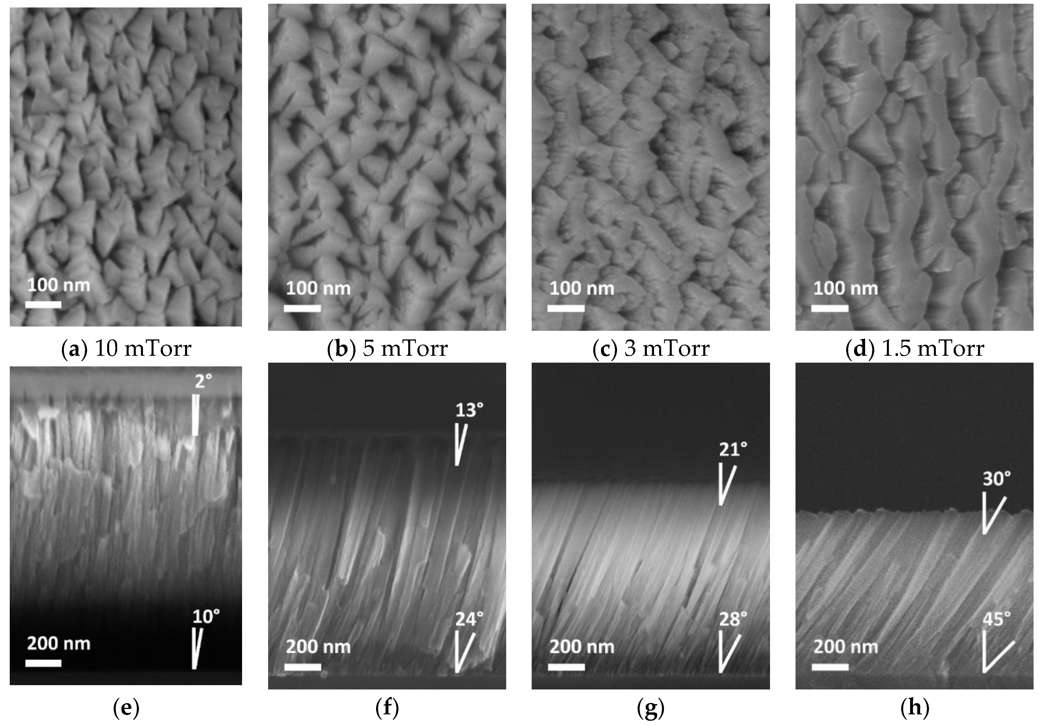
Figure 2 shows top- and side-view scanning electron microscope (SEM) images of AlN thin films grown in GLAD configuration, α = 85°, at different pressures, revealing columnar features in all samples while having different inclined angles, β, from the substrate’s normal. Physical attributes of the nanocolumns such as column length (L), column tilt (β) and overall film thickness (Tf) can be interpreted according to the illustration in Figure 1b. The AlN film grown at 10 mTorr working pressure (Figure 2a,e) exhibits a highly coalesced and faceted nanocolumnar morphology, with individual columns being about 40 nm wide and 1743 nm long, with the least inclination, β~5°. At 5 mTorr (Figure 2b,f), the columns appear to be about 30 nm wide, 1336 nm long and β~19°. Going further down in working pressure, at 3 mTorr (Figure 2c,g) the film morphology appears layered and fan-like, with the individual columns about 25 nm thick, inclined at 25° with a length of 1151 nm. At 1.5 mTorr working pressure (Figure 2d,h), the columns show maximum inclination with β up to ~38° while the length and thickness of nanocolumns further decrease to 1068 and 15 nm, respectively. The Tf is observed to be 1700, 1300, 950, and 800 nm at 10, 5, 3, and 1.5 mTorr working pressures, respectively, which are slightly smaller than the aforementioned column lengths due to β.
The above results clearly show that reducing the working pressure from 10 to 1.5 mTorr results in reduced column growth rates (from 14.5 to 8.9 nm/min), reduced Tf, smaller column diameters, but higher β from the substrate’s normal. Looking closely at Figure 2e–h, the film exhibits a slightly higher β at the beginning of deposition compared to the termination of the deposition process. The column diameters are smaller in the beginning but increase over time as the deposition progresses. This occurs due to the anisotropic nature of shadowing [18] and a “dragging mechanism” which mobilizes the incoming atoms on the nanocolumn surface [63]. This results in a slight bend (see side-view images) in the nanocolumn morphology when comparing the nanocolumn inclinations towards the start and end of film deposition. A lower working pressure leads to flat and coalesced column terminations with an overall porous microstructural density, which is typical of GLAD deposited thin films [64], while higher working pressures result in faceted column terminations. Area fraction estimations of the top-view SEM images was performed using ImageJ software to determine the porosity of the GLAD-deposited AlN columnar thin films at different working pressures. The porosity variation was calculated to be 8.7%, 12.9%, 17.8%, and 27.8% for AlN thin films grown at 10, 5, 3, and 1.5 mTorr working pressures, respectively. This indicates that porosity of GLAD deposited AlN columnar thin films increased with lowering working pressure. At lower pressures, the ballistic shadowing-assisted growth resulted in a layered, fan-like structure comprised of AlN nanocolumns with higher β coalesced to their adjacent neighbors, creating deeper trenches and hence resulting in an overall higher porosity.

3.2. Crystallographic Characteristics

As a result of GLAD characteristic, the growth direction of as-grown film often tilts away from substrate surface normal. Both morphology and microstructure of the film can vary with the use of deposition configuration. Therefore, θ/2θ-scan XRD, which can only measure the crystal planes parallel to the substrate surface, is an improper technique to investigate GLAD film. To study crystalline titling with respect to (w.r.t.) substrate surface normal and degree of fiber/biaxial texture, the XRD pole-figure measurement at a fixed 2θ angle, referred as pole or crystal plane, is performed by mapping the tilting angle, ψ: 0°–85°, and rotation angle, φ: 0°–360°, of the sample, controlled precisely by a goniometer in the diffractometer. To determine crystalline orientation of nanocolumns w.r.t. the substrate surface normal, ψ = 0°, two perpendicular planes, {0002} and {10 1 ¯ 0} corresponding to basal and prismatic planes, respectively, of wurtzite crystal were chosen.

3.2.1. GLAD: α = 85°

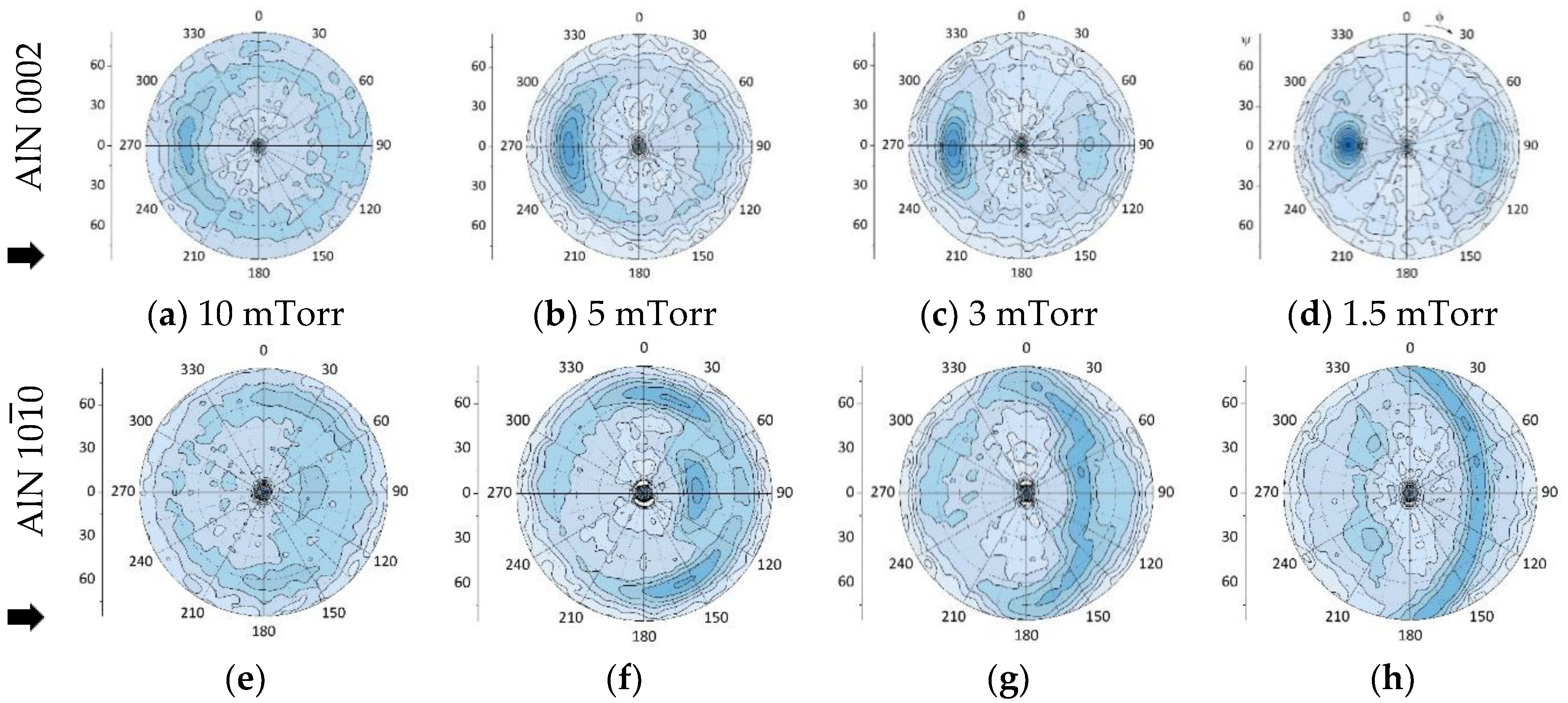
Figure 3 shows XRD pole figures of GLAD AlN columnar films obtained at diffraction angles of 2θ = 36.03° (top) and 33.2° (bottom), which are corresponding to the {0002} and {10 1 ¯ 0} of wurtzite AlN, respectively. With reducing the working pressure from 10 to 1.5 mTorr, the contour of 0002 pole figures (top figures) vary from a ring to two poles, respectively, but all with a dominant pole towards flux direction (marked with an arrow in the figure) at ψ~55°, indicating that the c plane, {0002}, of most nanocolumns tilts towards the sputtering source. The weak poles located at the opposite direction means a small number of domains have their c plane facing away from the source. As to the 10 1 ¯ 0 pole figures (bottom figures) of the samples grown at higher pressures, a maximum intensity of 10 1 ¯ 0 planes at ψ = 35° and 65° (1 strong pole at 35° arising from {10 1 ¯ 0}, 2 poles of weaker intensity at 65° from {1 1 ¯ 00} and {01 1 ¯ 0}) are observed for both 10 mTorr (Figure 3e) and 5 mTorr (Figure 3f) depositions, respectively, indicating that the basal plane orientation of crystallites have a high degree of ordering. Similar pole figures of the samples grown at 3 and 1.5 mTorr show that the 10 1 ¯ 0 poles become arc-like contours, indicating a disordered basal plane orientation of the crystallites. The above results exhibit an overall change from biaxial to fiber texture with c plane tilted toward to flux direction, as the working gas pressure is reduced.
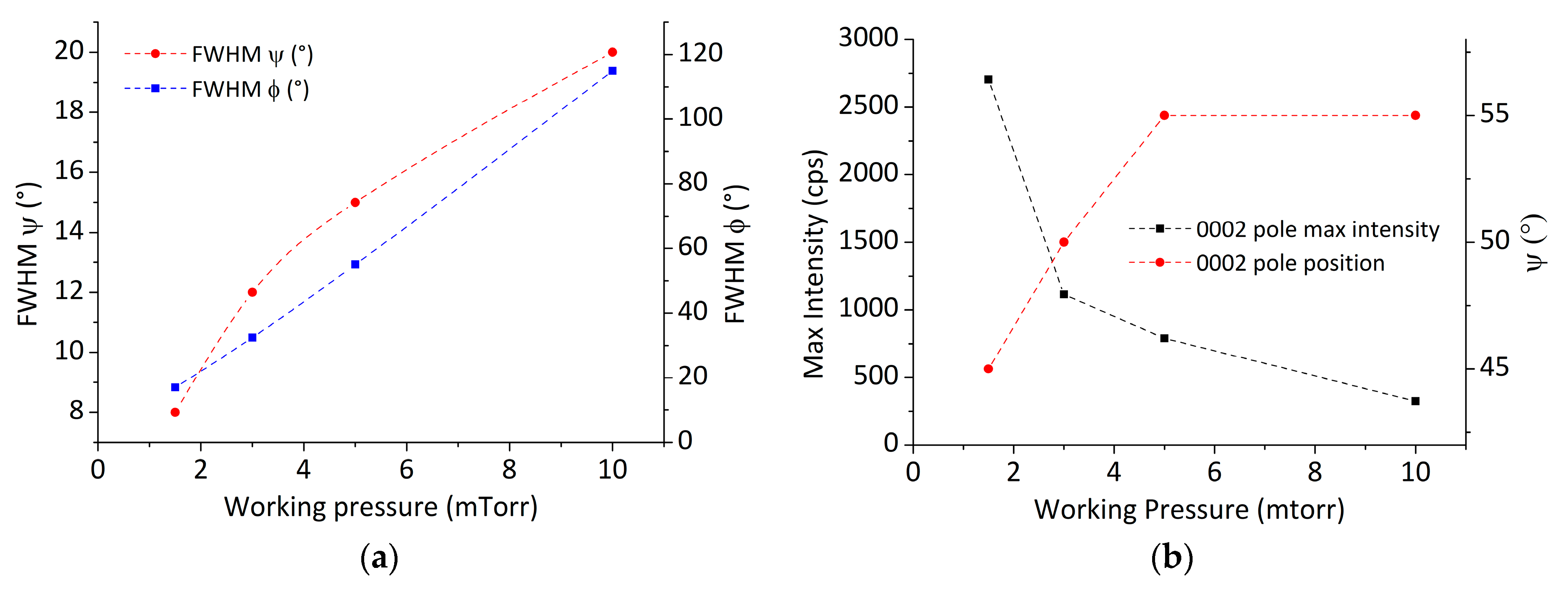
More details regarding grain alignment perpendicular and parallel to the substrate surface can be found from the full width at half maximum (FWHM) of the peaks and used to understand the degree of texture at different working gas pressures. In Figure 4 the graphs illustrate this information, where the FWHM values of AlN 0002 poles increase from 8° to 20° along ψ and 17° to 115° along φ directions, respectively (Figure 4a), and the maximum intensity of the AlN 0002 poles decreases from 2704 to 325 cps as the working gas pressure is increased from 1.5 to 10 mTorr (Figure 4b). The positions of AlN 0002 poles are observed at ψ = 45°, 50°, 55°, and 55° for 1.5, 3, 5, and 10 mTorr working pressures, respectively.
This means that at 10 mTorr working gas pressure the AlN c-axis is tilted by 55° w.r.t. substrate surface normal with a mosaic spread of ±10° and an azimuthal spread of ±57.5° around the c-axis; while at 1.5 mTorr working gas pressure, the AlN c-axis is tilted by 45° with respect to surface normal with a mosaic spread of ±4° and an azimuthal spread of ±8.5° around the c-axis, consistent with the pole figures in Figure 3.

3.2.2. Normal Deposition: α = 0°

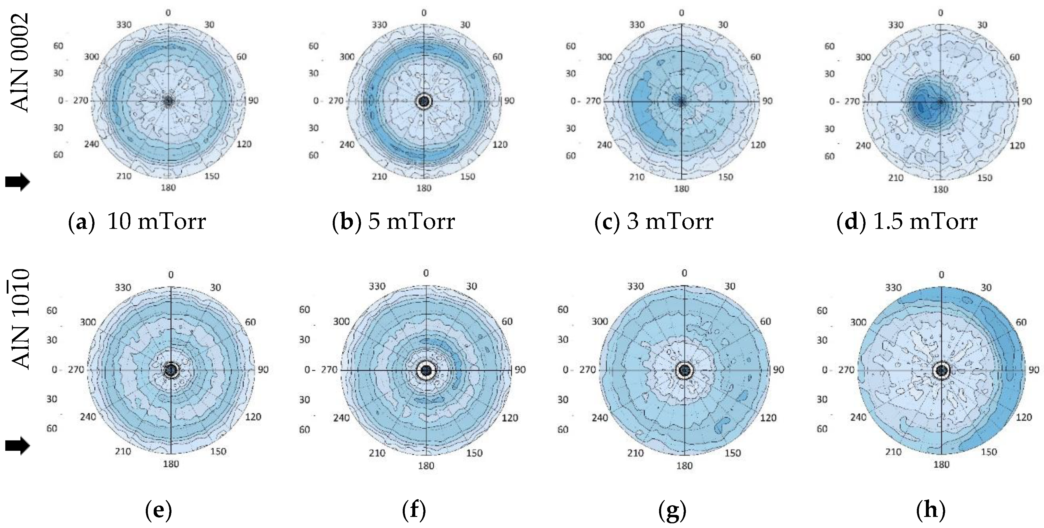
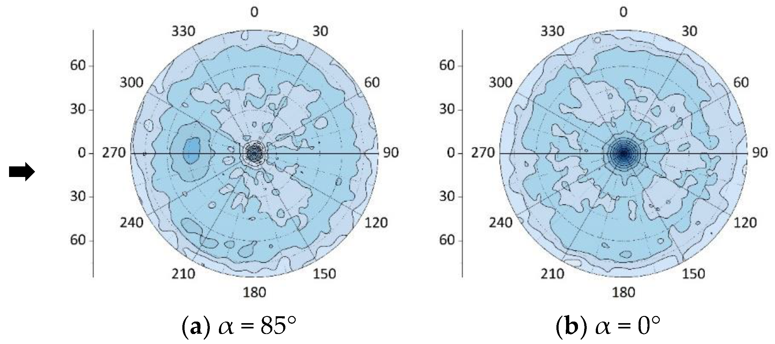
To further study the effect of incoming flux direction on the crystal orientation of as-grown AlN films, the pole figure measurement was performed on the AlN films deposited with the deposition flux parallel to the substrate normal (α = 0°) at different working pressures, shown in Figure 5. At higher working pressure, 10 and 5 mTorr, both 0002 and 10 1 ¯ 0 pole figures reveal the contour in the form of circular rings. Only one ring located at ψ around 60° is observed in the 0002 pole figures (Figure 5a,b), indicating a randomly oriented basal plane orientation with a 60° tilt around the growth direction. Two rings located at ψ around 30° and 60° are observed in 10 1 ¯ 0 pole figures (Figure 5e,f), which are attributed to the contribution of prismatic planes {1 1 ¯ 00} and {01 1 ¯ 0} of wurtzite AlN. The above results indicate that the AlN columnar films may be grown with one of pyramidal planes towards the flux direction. When the working pressure was reduced to 3 and 1.5 mTorr, the contour shown in 0002 pole figures (Figure 5c,d) becomes a dominant single pole located very close to the center, indicating that the AlN films were grown along the c-axis direction. (Note: The slight tilt of the pole is believed to be due to misalignment in substrate position with respect to flux direction.) As to the 10 1 ¯ 0 pole figures, no obvious ring or pole is expected to present because the prismatic planes are perpendicular to c plane. However, an arc contour located at ψ close to 90° is still observed in 1.5 mTorr sample’s pole figure (Figure 5h), which further confirms misalignment in substrate position during this sample deposition.
To further corroborate the transformation of dominant growth planes at different working gas pressures, XRD θ–2θ scans of AlN thin films grown with a normal configuration (α = 0°) were performed. Figure 6 shows a clear transition of crystal plane from 0002 (2θ = 36.12°) dominated growth at 1.5 mTorr to 10 1 ¯ 1 (2θ = 37.92°) dominated growth at 10 mTorr working gas pressure. Here, the peak positions are quite close to the strain-free bulk AlN, 2θ = 36.04° and 37.91° for AlN(0002) and AlN (10 1 ¯ 1) respectively, extracted from International Centre for Diffraction Data (ICDD) reference code 00-025-1133, indicating that the formed AlN individual nanocolumns were grown close to stoichiometry. However, a very small peak located at ~38.3°, referred to Al (111), is observed at 3 and 1.5 mTorr, indicating the growth is under a slightly N insufficient condition.

3.2.3. Short-Time Growth for Both α = 85° and 0°

As the working gas pressure is reduced, the 0002 poles appear more concentrated and show a tendency of tilting towards to the source, thereby indicating c-axis growth is flux dominated at lower pressures and its direction is primarily guided by incident flux direction. This preferred orientation was further studied by investigating AlN 0002 pole figures for a short deposition time (30 min) both using GLAD and normal deposition configurations, shown in Figure 7a,b, respectively. The ψ angles of AlN 0002 poles are almost the same as angles obtained from the 120 min deposition films located at 45° and 0° for α = 85° and 0°, respectively. The result of c-axis growth dominated by incoming flux direction at lower pressures indicates that the evolution of a preferred orientation starts early in the deposition process.
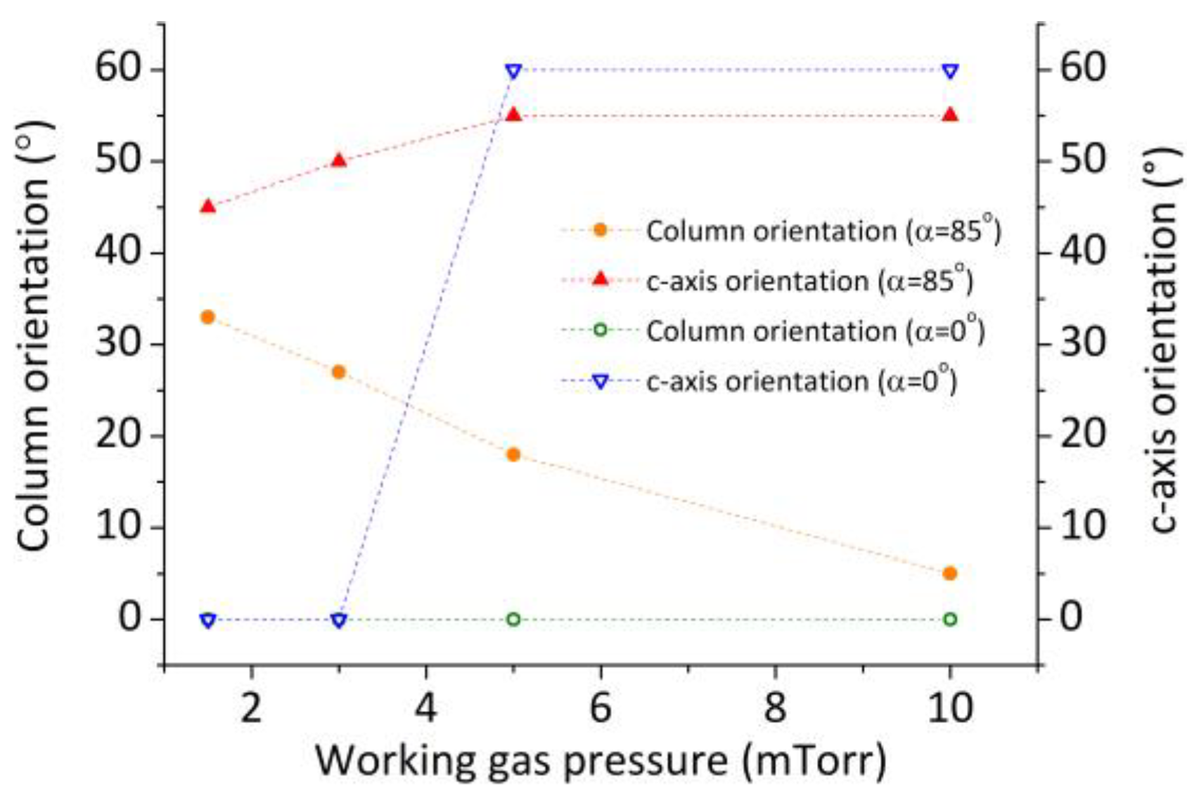
Figure 8 summarizes the above results. For GLAD-deposited columnar AlN thin films, lower working pressure results in increased β from the substrate normal, with the c-axis inclined towards the source by an angle between 45° and 55°. At higher working pressure, β reduces significantly but the c-plane remains inclined towards the source by 55°. For normally deposited columnar AlN thin films, lower working gas pressures did not affect the growth direction of the individual columns and they remain oriented perpendicular to the substrate surface. However, increasing the working pressure from 3 to 5 mTorr results in the c-axis tilt abruptly changing from 0° to around 60°.

3.3. Metal Flux Simulations

The average angle of incidence, α and average energy of sputtered metal flux, E p arrived at the substrate was simulated using SiMTra at the same working conditions as GLAD depositions. Figure 9 shows the average α of incoming particles deposited on the substrate. The top and bottom edge of the maps represents substrate sides facing toward and away from the target, respectively. The actual substrate dimensions and position used in the experiments is represented in the form of a dashed-line square. From the following figures it can be observed that as working pressure decreases from 10 to 1.5 mTorr, the average α increases from about 46° to 59° (Figure 9a–d) and about 48° to 66° (Figure 9e–h) from the surface normal for Ar and N, respectively. This indicates a strong correlation between α of the incoming particles with working pressure, even when the substrate position and tilt were kept constant with regard to the source.
Looking at average E P , as the working pressure is reduced from 10 to 1.5 mTorr, average E P increased from about 2.5 to 5 eV (Figure 10a–d) and about 6 to 14 eV (Figure 10e–h) for Ar and N sputter gases, respectively. This suggests incoming particles reach the substrate with a higher average energy in lower working pressures, compared to higher working pressures. Coupled with the average α obtained for the same working pressures, the trends are in line with the morphology of the nanocolumns obtained from our experiments, suggesting high energy adatoms with a higher α at lower working pressures resulting in a greater tilted morphology of the nanocolumns and vice versa. These maps also reveal a collimation of the arriving flux at the substrate at low working pressures, suggesting less scattering and resulting in an overall higher energy. As working pressure increases, the incoming particles undergo more scattering and the flux loses its directionality, resulting in particles reaching the substrate with an overall lower energy. This can be evidenced by observing the lack of directionality in the metal flux reaching the substrate at higher pressures.

4. Discussion

4.1. GLAD Configuration

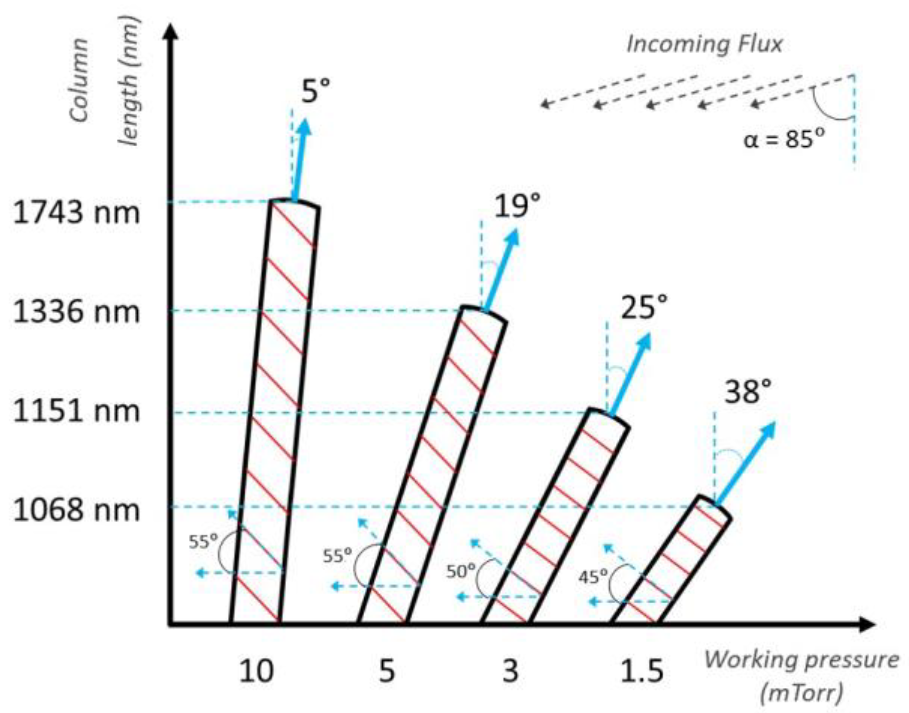
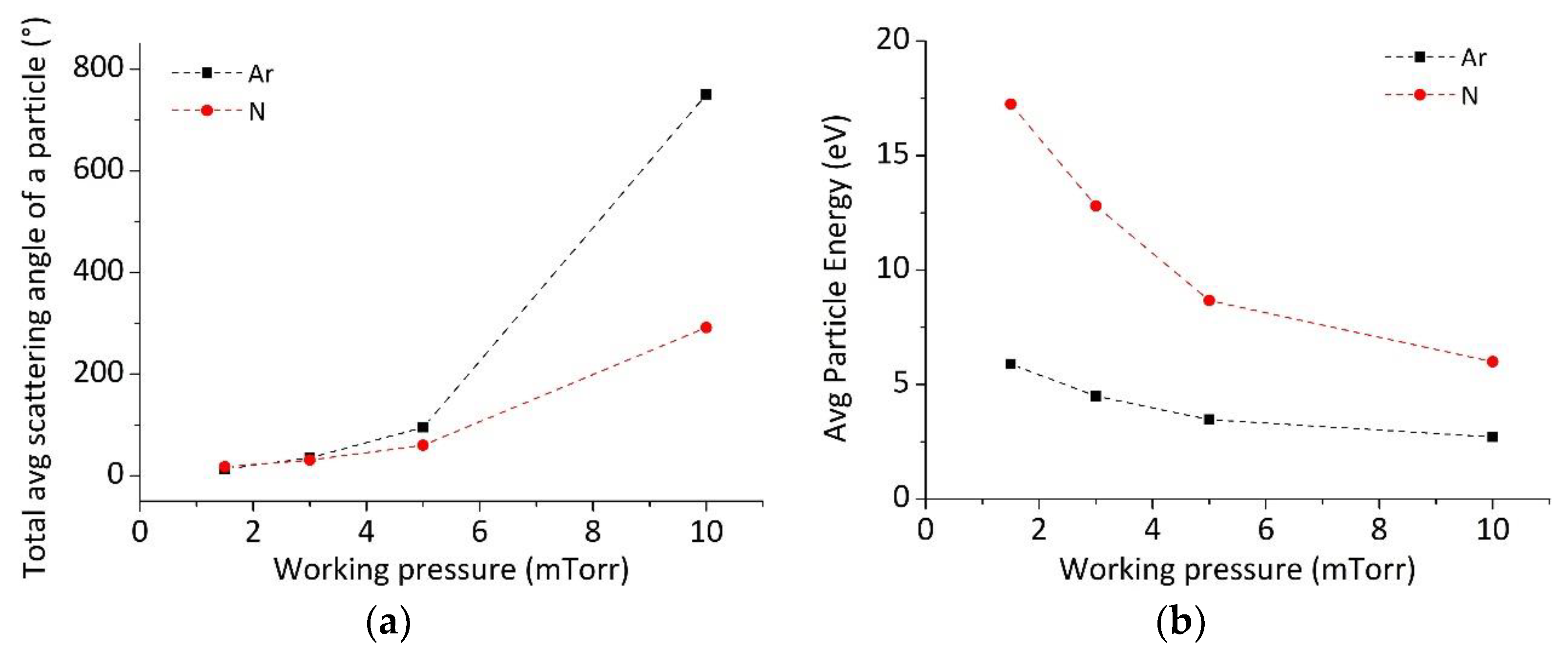
Figure 11 summarizes the column inclinations (β) and heights of AlN columnar thin films grown at different working gas pressures in GLAD configuration with the same angle of flux incidence (α = 85°). Growth at higher working gas pressures of 10 and 5 mTorr is primarily due to ambient flux-dominated deposition, where the incoming particles have a shorter mean free path (λ~1 cm), allowing for more collisions in the gas phase. This can also be observed in our SiMTra simulations where, the mean total accumulated scattering angle of the incoming particles is very high at higher working pressures (Figure 12a). This results in particles arriving at the substrate with a lower mean average E P (Figure 12b), compared to that at lower working pressures. Here, the mean total accumulated scattering angle refers to the sum of all angles that a particle undergoes after scattering multiple times. Note that Figure 9a–h and Figure 10a–h show gradient maps of average α and average E P of the metal flux reaching the substrate at different working pressures; while Figure 12a,b summarizes the mean of the average total accumulated scattering angle and average E P .
As a result, the arriving Al atoms have a larger angular spread and less kinetic energy to undergo significant surface diffusion. The adatoms tend to stick at their landing sites, resulting in column diameter expansion and eventually in coalesced columns with smaller tilt angles β as there is not much shadowing involved even when using a large angle for the incident flux. The higher working pressure is also responsible for a higher amount of deposition flux reaching the substrate for the same deposition time. Consequently, new atoms bury the recently deposited adatoms before they have the time to undergo any significant surface diffusion, resulting in an overall denser morphology of nanocolumns growing almost perpendicular to the substrate. The faceted triangular column terminations were found to orient themselves such that the corner with the largest angle faces the direction of incoming flux corresponding to an in-plane texture (discussed in 4.2) [58], along with the fact that even when the columns grew almost perpendicular to the substrate (β = 5°), the c-axis remained tilted towards the source (55°).
In contrast, at lower pressures of 3 and 1.5 mTorr the incoming atoms arrive at the substrate surface with higher energies owing to λ being larger (~6 cm). However, the adatom mobility is still insufficient for any significant surface diffusion at room temperature, resulting in a kinematically limited growth dominated by ballistic shadowing. Consequently, the film has columns with smaller diameters showing that surface diffusion does not counteract shadowing as the adatoms tend to stick to the tips of the columns and do not diffuse towards the shadowed regions [57]. In addition, the column terminations appear flat as a consequence of (i) the plane at fastest growth direction being extinguished by planes having equal growth rates and (ii) coalescence due to column broadening [18,57,64] and the fact that (iii) higher incident energies of the adatoms result in highly localized temperature spikes allowing the surface atoms to hop to more stable lattice sites [65]. However, this hopping distance is of short-range order (~20 Å) and is not significant enough to affect the overall morphology or growth behavior of the nanocolumns. Figure 13 illustrates the morphology of columnar AlN films at higher (Figure 13a) and lower (Figure 13b) working gas pressures during their initial and final growth stages. The red lines represent the c-axis tilt based on the information from the XRD pole figure measurements, while the insets show higher magnification SEM images of column terminations of as grown films. It can be observed that at higher pressures, even when the columnar morphology is almost perpendicular to the substrate surface, (0002) remains tilted towards the Al source. This is primarily because at higher pressure there is significant scattering amongst the reactive species and the adatoms do not arrive at the substrate from just one direction and have comparatively less energy, resulting in a slower growth rate of (0002) as the incoming adatoms encounter a higher diffusion barrier compared to {1 1 ¯ 0 0} and {11 2 ¯ 0 } [66]. This in turn leads to growth of AlN nanocolumns almost perpendicular to the substrate normal, but with inclined (0002).
Preferred orientation has been extensively studied [67,68,69] and basically stems from a preferred orientation during the nucleation stage or competitive growth and can be affected by a variety of deposition parameters such as temperature, flux intensity, direction of incoming flux and reactive gas composition. As a result, there is a competitive growth taking place where the highly scattered incoming adatoms result in the growth of nanocolumns almost perpendicular to the substrate, but the (0002) remains inclined due to the oblique placement of the source. As λ is shorter, the adatoms have lower energy and the growth rate of (0002) is much smaller than that of (10 1 ¯ 0), resulting in a comparatively denser film with faster lateral growth at 10 mTorr. The slower growth rate of (0002) is attributed to the fact that the bond formation energy of Al-N bonds along [0001] is higher compared to that along [2 11 ¯ 0] at higher pressure [70,71]. Density functional theory (DFT) calculations made by Jindal et al. to generate potential energy surfaces for Al and N adatoms suggest higher diffusion barriers, in general, for the adatoms along (0002), compared to {1 1 ¯ 0 0} and {11 2 ¯ 0 } [66], indicating a requirement of higher energy incident flux for the formation of AlN (0002). It was also found that multiple minimum energy positions existed for the N adatoms (hence, lower diffusion barriers) along {1 1 ¯ 0 0} and {11 2 ¯ 0 } compared to Al, leading to a slower growth rate of (0002).
SiMTra simulations in Figure 14 show a higher number of particles reaching the substrate at 10 mTorr and this combined with the DFT calculations presented in [66] explain an easier pathway for growth of AlN nanocolumns almost perpendicular to the substrate compared to the inclined (0002) growth. This effect is enhanced when the higher amount of deposition flux reaching the substrate buries the recently deposited adatoms thereby mitigating any chances of significant surface diffusion. This results in columns terminating with 0002 facets inclined towards the source, where the faceted termination corresponds to an evolutionary selection process starting at the nucleation stage as the oblique source placement creates a crystal habit for the initial nuclei [57,58]. In this case, due to the lower process temperature and high partial pressure of N2/Ar (N2:Ar = 1:1), coupled with high scattering at a high working gas pressure, the fastest growth direction is almost perpendicular to the substrate and results in a crystal shape terminating with planes having a slower growth rate.

4.2. Variation in Biaxial Texture in GLAD Columnar Films

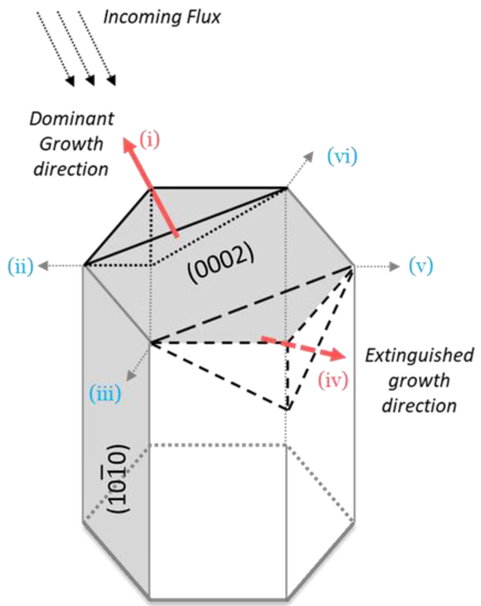
Analyzing the pole figures of columnar AlN films deposited at higher pressures using GLAD (Figure 3a,b,e,f) both the poles arise from the same grain orientation corresponding to the 0002 pole, hence suggesting a biaxial texture. However, broader contours of 0002 poles indicate a lower degree of order in its orientation hence resulting in a lower degree of biaxial texture. In contrast, AlN pole figures at lower pressures (Figure 3c–h) show more defined 0002 poles, indicating a higher degree of orientation, but broader 10 1 ¯ 0 poles, indicating an azimuthally random basal plane orientation. This variation in orientation is possibly because at higher pressures, growth of Al–N bonds along [2 11 ¯ 0] are preferred over [0001] due to comparatively lower diffusion barrier [66] and smaller bond formation energy requirements [11,70]. Another possibility is a higher island nucleation rate at the side planes compared to the c-plane resulting in a higher probability of adatom capture when the facets are facing the source [58]. At lower pressures, the higher kinetic energy condition favors growth along [0001], resulting in randomly oriented {10 1 ¯ 0} planes along the c-axis. This in-plane orientation can be attributed to the so called ‘capture cross section area’ of the initial nuclei [58,72], where the nuclei with their longest edge perpendicular to the incident flux are more capable of capturing the incoming adatoms (in Figure 15, (i) and (iv) dominate over other directions). As neighboring nuclei coalesce to form larger nuclei and in turn tiny islands, they grow in size and cast larger shadows on other neighboring nuclei clusters. As a result of Ostwald ripening and ballistic shadowing, growth rates of these larger nuclei dominate over other smaller shadowed nuclei. This coincides with the 0002 pole figures as we see two grain populations with one having a much higher intensity than the other, and this phenomenon becomes more pronounced at lower working gas pressures (Figure 3c,d) due to stronger directionality of incoming flux. A longitudinal scratch was made along the edge of substrates to mark the direction towards the source. This, along with observations from SEM data, confirmed that growth was dominant along the direction of incident flux.
Also, from the plots in Figure 4a, as we move higher in the working gas pressure regime, the FWHM in both the ψ and φ directions decreases. This indicates a stronger and more confined out-of-plane grain alignment with lower working gas pressure owing to greater directionality, higher adatom mobility and less scattering at lower pressures. The small variation in c-axis tilts with respect to the substrate surface coupled with smaller angular spread and higher maximum intensity of 0002 poles (Figure 4b) at lower working gas pressures further confirms this argument. However, the overall lower intensity of the poles is attributed to lower deposition rates and smaller layer thicknesses related to the asymmetric deposition configuration.

4.3. Evolution of AlN Crystal Plane with Working Pressure in Normal Deposition Configuration

The evolution of AlN crystal planes with working pressure in normal deposition configuration, α = 0°, is depicted in Figure 5 and Figure 6. We see (10 1 ¯ 1) dominated growth at the higher pressures which transforms to (0002) dominated growth at lower pressures, while the columnar AlN films grow parallel to the substrate normal (not shown here). This change in preferred orientation has been widely studied (e.g., Iqbal et al. provide an extensive list of sources in their review [73]) and can be explained in terms of (i) E P of the incoming flux and (ii) amount of N2 in the partial pressure atmosphere. From SiMTra simulations in Figure 12, average E P of the incoming particles is lower at higher working pressures, due to the significantly higher amount of scattering. This lower E P in turn results in preferential growth along 10 1 ¯ 1 plane normal due to lower diffusion barrier and lower bond formation energy requirements compared to 0001 direction as discussed in Section 4.1. In addition to that, the amount of reactive gas in the partial pressure environment can affect preferential growth. This can be tailored by varying the N2 flow rate [11,74,75,76,77,78]. A higher total working pressure (and hence increased amount of N2, while keeping the same partial pressure ratio of N2:Ar = 1:1) results in an overall decrease in the kinetic energy of adatoms as a consequence of the lighter atomic mass of nitrogen particles (N2+, N2, and N) being dominant near the target surface and not being able to transfer their energy to the target atoms sufficiently [11]. As a result, Al adatoms do not have enough kinetic energy to rearrange themselves along (0002). At lower total working pressure (and hence lower amount of N2), Ar ions are in excess and with its higher atomic mass it leads to higher kinetic energy adatoms resulting in c-axis dominated growth [11]. This can be corroborated from the XRD 2θ measurements in Figure 6, which shows the (10 1 ¯ 1) preferential orientation of AlN nanocolumns at 10 mTorr working pressure and (0002) preferential orientation of AlN nanocolumns at 1.5 mTorr working pressure. Coupled to this, the difference in total working pressure results in a variation in λ, thereby increasing the average number of particles reaching the substrate with significantly lower energy compared to those arriving at a lower working pressure (Figure 14 and Figure 12b) along with differences in diffusion barrier energies of different wurtzite crystal planes [66] lead to (10 1 ¯ 1) dominated growth at higher pressures and (0002) dominated growth at lower pressures. Contrary to most reports of (10 1 ¯ 0) preferred growth of AlN thin films at higher pressures (where different N2/Ar ratios were used), our depositions were performed at a unity N2/Ar ratio of 1:1. This, coupled with the other experimental conditions used in our study are responsible for the AlN (10 1 ¯ 1) preferential orientation at higher working gas pressures.

5. Conclusions

Columnar AlN thin films were grown on Si (111) using DC reactive magnetron sputtering in GLAD and normal deposition configurations at different working pressures in the range of 1.5 to 10 mTorr. A mixture of Ar and N2 in 1:1 ratio was used as the working gas and reactive gas, respectively, and the growth mechanism of columnar AlN thin films grown using the two configurations was studied at different pressures. The growth behavior of AlN nanocolumns is found to be highly dependent on working pressure and the direction of incoming flux.
In GLAD configuration, the growth direction of nanocolumns varies from 2° to 38° w.r.t substrate normal with decreasing working pressure from 10 to 1.5 mTorr, while the c-axis orientation of the nanocolumns is almost the same, revealing an inclination towards the source by an angle ~55°. In addition, higher working gas pressures resulted in growing longer column lengths and higher density thanks to increased coalescence. A biaxial texture evolution was also observed at higher pressures where oblique placement of the source created a preferential orientation of the crystal habit, resulting in a higher degree of basal plane alignment. In normal deposition configuration, varying working gas pressures did not affect the nanocolumn growth direction. However, increasing the working pressure from 3 to 5 mTorr leads to the c-axis tilt abruptly changing from 0° to around 60° due to increased scattering and lower energy incoming flux. This resulted in preferential growth along the direction with lower energy requirements.
The evolution of nanocolumn morphology and crystal orientation varied by working pressure and direction of flux is well elucidated by the model of kinetic energy dominated growth process. Results from SiMTra simulations corroborate our GLAD observations where the average α and average E P decreased with increasing working pressures, thereby resulting in lower β as the working pressure was increased. Our results show that lower working pressures are crucial for guiding high energy incident flux and establish a basis for further growth and characterization of twisted and helicoidal binary and ternary nanostructures.

Author Contributions

Conceptualization, S.B., K.J., J.B., and C.-L.H.; methodology, S.B., F.E., and C.-L.H.; software, S.B. and F.E.; validation, S.B., K.J., F.E., L.H., J.B., and C.-L.H.; resources, K.J., L.H., and J.B.; data curation, S.B., F.E., and C.-L.H.; writing—original draft preparation, S.B. and C.-L.H.; writing—review and editing, S.B., K.J., F.E., L.H., J.B., and C.-L.H.; supervision, K.J., J.B., and C.-L.H.; funding acquisition, K.J., J.B., and C.-L.H. All authors have read and agreed to the published version of the manuscript.

Funding

This research was funded by Vetenskapsrådet (grant number 2018-04198), Energimyndigheten (grant number 46658-1), and Stiftelsen Olle Engkvist Byggmästare (grant number 197-0210) and the APC was funded by Linköping University Library. The Swedish Government Strategic Research Area in Materials Science on Functional Materials at Linköping University (Faculty Grant SFO-Mat-LiU 2009-00971) is acknowledged for financial support.

Conflicts of Interest

The authors declare no conflict of interest.

References

  1. Hochbaum, A.I.; Yang, P. Semiconductor nanowires for energy conversion. Chem. Rev. 2010, 110, 527–546. [Google Scholar] [CrossRef]
  2. Szczech, J.R.; Higgins, J.M.; Jin, S. Enhancement of the thermoelectric properties in nanoscale and nanostructured materials. J. Mater. Chem. 2011, 21, 4037–4055. [Google Scholar] [CrossRef]
  3. Bierman, M.J.; Jin, S. Potential applications of hierarchical branching nanowires in solar energy conversion. Energy Environ. Sci. 2009, 2, 1050. [Google Scholar] [CrossRef]
  4. Pişkin, F.; Bliem, R.; Yildiz, B. Effect of crystal orientation on the segregation of aliovalent dopants at the surface of La0.6Sr0.4CoO3. J. Mater. Chem. A 2018, 6, 14136–14145. [Google Scholar] [CrossRef] [Green Version]
  5. Wang, R.; Tong, Y.; Manzi, A.; Wang, K.; Fu, Z.; Kentzinger, E.; Feldmann, J.; Urban, A.S.; Müller-Buschbaum, P.; Frielinghaus, H. Preferential orientation of crystals induced by incorporation of organic ligands in mixed-dimensional hybrid perovskite films. Adv. Opt. Mater. 2018, 6, 1701311. [Google Scholar] [CrossRef]
  6. Hu, Y.; Zhu, J.; Zhang, C.; Yang, W.; Fu, L.; Li, D.; Zhou, L. Understanding the preferred crystal orientation of sputtered silver in Ar/N2 atmosphere: A microstructure investigation. Adv. Mater. Sci. Eng. 2019, 1–8. [Google Scholar] [CrossRef] [Green Version]
  7. Yang, B.; Wang, C.; Yuan, Z.; Chen, S.; He, Y.; Song, H.; Ding, R.; Zhao, Y.; Tang, J. Hydrazine solution processed CuSbSe2: Temperature dependent phase and crystal orientation evolution. Sol. Energy Mater. Sol. Cells 2017, 168, 112–118. [Google Scholar] [CrossRef]
  8. Ruys, A. Alumina as an electrical insulator. In Alumina Ceramics; Elsevier: Amsterdam, The Netherlands, 2019; pp. 413–445. [Google Scholar]
  9. Mylvaganam, K.; Chen, Y.; Liu, W.; Liu, M.; Zhang, L. Hard thin films: Applications and challenges. In Anti-Abrasive Nanocoatings: Current and Future Applications; Elsevier Inc.: Amsterdam, The Netherlands, 2014; pp. 544–567. ISBN 9780857092175. [Google Scholar]
  10. Petti, C.J.; Hilali, M.M.; Prabhu, G. Thin Films in Photovoltaics. In Handbook of Thin Film Deposition: Techniques, Processes, and Technologies, 3rd ed.; Elsevier Inc.: Amsterdam, The Netherlands, 2012; pp. 313–359. ISBN 9781437778748. [Google Scholar]
  11. Iqbal, A.; Walker, G.; Iacopi, A.; Mohd-Yasin, F. Controlled sputtering of AlN (002) and (101) crystal orientations on epitaxial 3C-SiC-on-Si (100) substrate. J. Cryst. Growth 2016, 440, 76–80. [Google Scholar] [CrossRef]
  12. Greene, J.E. Tracing the 5000-year recorded history of inorganic thin films from ∼3000 BC to the early 1900s AD. Appl. Phys. Rev. 2014, 1, 41302. [Google Scholar] [CrossRef] [Green Version]
  13. Robbie, K.; Brett, M.J.; Lakhtakia, A. Chiral sculptured thin films. Nature 1996, 384, 616. [Google Scholar] [CrossRef]
  14. Jen, Y.-J.; Lin, C.-F. Anisotropic optical thin films finely sculptured by substrate sweep technology. Opt. Express 2008, 16, 5372–5377. [Google Scholar] [CrossRef]
  15. Pessoa, R.S.; Fraga, M.A. Biomedical applications of ultrathin atomic layer deposited metal oxide films on polymeric materials. Front. Nanosci. 2019, 14, 291–307. [Google Scholar]
  16. Lein, H.L. Coatings and surfaces with hydrophobic and anti-icing properties. Front. Nanosci. 2019, 14, 257–269. [Google Scholar]
  17. Miranti, R.; Parisi, J. Spectroscopic and electrical properties of hybrid thin films for solar cell applications. Front. Nanosci. 2019, 14, 271–290. [Google Scholar]
  18. Hawkeye, M.M.; Brett, M.J. Glancing angle deposition: Fabrication, properties, and applications of micro- and nanostructured thin films. J. Vac. Sci. Technol. A Vac. Surf. Films 2007, 25, 1317–1335. [Google Scholar] [CrossRef]
  19. Barranco, A.; Borras, A.; Gonzalez-Elipe, A.R.; Palmero, A. Perspectives on oblique angle deposition of thin films: From fundamentals to devices. Prog. Mater. Sci. 2016, 76, 59–153. [Google Scholar] [CrossRef] [Green Version]
  20. Zhou, C.M.; Gall, D. Development of two-level porosity during glancing angle deposition. J. Appl. Phys. 2008, 103, 14307. [Google Scholar] [CrossRef]
  21. Kundt, A. Ueber doppelbrechung des lichtes in metallschichten, welche durch zerstäuben einer kathode hergestellt sind. Ann. Phys. Chem. 1886, 263, 59–71. [Google Scholar] [CrossRef] [Green Version]
  22. Salinger, H.; Beutler, E. Der König in Thule und die dichtungen von der lorelay. Books Abroad 1950, 24, 64. [Google Scholar] [CrossRef]
  23. Liedtke, S.; Grüner, C.; Lotnyk, A.; Rauschenbach, B. Glancing angle deposition of sculptured thin metal films at room temperature. Nanotechnology 2017, 28, 385604. [Google Scholar] [CrossRef] [Green Version]
  24. Besnard, A.; Martin, N.; Millot, C.; Gavoille, J.; Salut, R. Effect of sputtering pressure on some properties of chromium thin films obliquely deposited. IOP Conf. Ser. Mater. Sci. Eng. 2010, 12, 12015. [Google Scholar] [CrossRef]
  25. Messier, R.F.; Sunal, P.D.; Venugopal, V.C. Evolution of sculptured thin films. Eng. Nanostruct. Films Mater. 1999, 3790, 133–141. [Google Scholar]
  26. Suzuki, M. Practical applications of thin films nanostructured by shadowing growth. J. Nanophotonics 2013, 7, 73598. [Google Scholar] [CrossRef]
  27. Kesapragada, S.V.; Sotherland, P.R.; Gall, D. Ta nanotubes grown by glancing angle deposition. J. Vac. Sci. Technol. B Microelectron. Nanometer Struct. 2008, 26, 678. [Google Scholar] [CrossRef]
  28. Zhou, C.M.; Gall, D. The structure of Ta nanopillars grown by glancing angle deposition. Thin Solid Films 2006, 515, 1223–1227. [Google Scholar] [CrossRef]
  29. Charles, C.; Martin, N.; Devel, M. Optical properties of nanostructured WO3 thin films by glancing angle deposition: Comparison between experiment and simulation. Surf. Coat. Technol. 2015, 276, 136–140. [Google Scholar] [CrossRef]
  30. Xu, X.; Arab Pour Yazdi, M.; Sanchez, J.-B.; Billard, A.; Berger, F.; Martin, N. Exploiting the dodecane and ozone sensing capabilities of nanostructured tungsten oxide films. Sens. Actuators B Chem. 2018, 266, 773–783. [Google Scholar] [CrossRef]
  31. Lakhtakia, A. Sculptured thin films: Accomplishments and emerging uses. Mater. Sci. Eng. C 2002, 19, 427–434. [Google Scholar] [CrossRef] [Green Version]
  32. Lintymer, J.; Martin, N.; Chappé, J.-M.; Delobelle, P.; Takadoum, J. Nanoindentation of chromium zigzag thin films sputter deposited. Surf. Coat. Technol. 2005, 200, 269–272. [Google Scholar] [CrossRef]
  33. Singh, J.P.; Tang, F.; Karabacak, T.; Lu, T.-M.; Wang, G.-C. Enhanced cold field emission from 〈100〉 oriented β–W nanoemitters. J. Vac. Sci. Technol. B Microelectron. Nanometer Struct. 2004, 22, 1048. [Google Scholar] [CrossRef]
  34. Singh, A.; Sharma, A.; Tomar, M.; Gupta, V. Tunable nanostructured columnar growth of SnO2 for efficient detection of CO gas. Nanotechnology 2018, 29, 65502. [Google Scholar] [CrossRef]
  35. Xi, J.-Q.; Schubert, M.F.; Kim, J.K.; Schubert, E.F.; Chen, M.; Lin, S.-Y.; Liu, W.; Smart, J.A. Optical thin-film materials with low refractive index for broadband elimination of Fresnel reflection. Nat. Photonics 2007, 1, 176–179. [Google Scholar] [CrossRef]
  36. Parra-Barranco, J.; Oliva-Ramirez, M.; Gonzalez-Garcia, L.; Alcaire, M.; Macias-Montero, M.; Borras, A.; Frutos, F.; Gonzalez-Elipe, A.R.; Barranco, A. Bending induced self-organized switchable gratings on polymeric substrates. ACS Appl. Mater. Interfaces 2014, 6, 11924–11931. [Google Scholar] [CrossRef]
  37. Chi, P.-W.; Su, C.-W.; Wei, D.-H. Control of hydrophobic surface and wetting states in ultra-flat ZnO films by GLAD method. Appl. Surf. Sci. 2017, 404, 380–387. [Google Scholar] [CrossRef]
  38. Allenstein, U.; Wisotzki, E.I.; Gräfe, C.; Clement, J.H.; Liu, Y.; Schroers, J.; Mayr, S.G. Binary Fe-Pd submicron structures fabricated through glancing angle deposition (GLAD) for bioapplications. Mater. Des. 2017, 131, 366–374. [Google Scholar] [CrossRef]
  39. Petrov, I.; Barna, P.B.; Hultman, L.; Greene, J.E. Microstructural evolution during film growth. J. Vac. Sci. Technol. A Vac. Surf. Films 2003, 21, S117–S128. [Google Scholar] [CrossRef]
  40. Hsiao, C.L.; Palisaitis, J.; Persson, P.O.Å.; Junaid, M.; Serban, E.A.; Sandström, P.; Hultman, L.; Birch, J. Nucleation and core-shell formation mechanism of self-induced InxAl1–xN core-shell nanorods grown on sapphire substrates by magnetron sputter epitaxy. Vacuum 2016, 131, 39–43. [Google Scholar] [CrossRef] [Green Version]
  41. Serban, E.A.; Palisaitis, J.; Yeh, C.C.; Hsu, H.C.; Tsai, Y.L.; Kuo, H.C.; Junaid, M.; Hultman, L.; Persson, P.O.Å.; Birch, J.; et al. Selective-area growth of single-crystal wurtzite GaN nanorods on SiOx/Si(001) substrates by reactive magnetron sputter epitaxy exhibiting single-mode lasing. Sci. Rep. 2017, 7, 1–11. [Google Scholar]
  42. Niewehuizen, J.M.; Haanstra, H.B. Microfractography of thin films. Philips Tech. Rev. 1966, 27, 87–91. [Google Scholar]
  43. Tait, R.N.; Smy, T.; Brett, M.J. Modelling and characterization of columnar growth in evaporated films. Thin Solid Films 1993, 226, 196–201. [Google Scholar] [CrossRef]
  44. Meakin, P. Ballistic deposition onto inclined surfaces. Phys. Rev. A 1988, 38, 994–1004. [Google Scholar] [CrossRef]
  45. Lichter, S.; Chen, J. Model for columnar microstructure of thin solid films. Phys. Rev. Lett. 1986, 56, 1396–1399. [Google Scholar] [CrossRef]
  46. Tanto, B.; Ten Eyck, G.; Lu, T.-M.M. A model for column angle evolution during oblique angle deposition. J. Appl. Phys. 2010, 108, 2008–2011. [Google Scholar] [CrossRef]
  47. Grüner, C.; Liedtke, S.; Bauer, J.; Mayr, S.G.; Rauschenbach, B. Morphology of thin films formed by oblique physical vapor deposition. ACS Appl. Nano Mater. 2018, 1, 1370–1376. [Google Scholar] [CrossRef]
  48. Shetty, A.R.; Karimi, A. Texture mechanisms and microstructure of biaxial thin films grown by oblique angle deposition. Phys. Status Solidi Basic Res. 2012, 249, 1531–1540. [Google Scholar] [CrossRef]
  49. Wu, Q. Circular polarization filters made of chiral sculptured thin films: Experimental and simulation results. Opt. Eng. 2000, 39, 1863. [Google Scholar] [CrossRef]
  50. Lakhtakia, A. Experimental realization of sculptured-thin-film polarization-discriminatory light-handedness inverters. Opt. Eng. 2000, 39, 2831–2834. [Google Scholar] [CrossRef]
  51. Hodgkinson, I.J.; Wu, Q.H.; Lakhtakia, A.; McCall, M.W. Spectral-hole filter fabricated using sculptured thin-film technology. Opt. Commun. 2000, 177, 79–84. [Google Scholar] [CrossRef]
  52. García-Méndez, M.; Morales-Rodríguez, S.; Machorro, R.; De La Cruz, W. Characterization of ALN thin films deposited by DC reactive magnetron sputtering. Rev. Mex. Fis. 2008, 54, 271–278. [Google Scholar]
  53. Zhang, X.-H.H.; Shao, R.-W.W.; Jin, L.; Wang, J.-Y.Y.; Zheng, K.; Zhao, C.-L.L.; Han, J.-C.C.; Chen, B.; Sekiguchi, T.; Zhang, Z.; et al. Helical growth of aluminum nitride: New insights into its growth habit from nanostructures to single crystals. Sci. Rep. 2015, 5, 1–12. [Google Scholar] [CrossRef] [Green Version]
  54. Wu, Q.; Hu, Z.; Wang, X.; Lu, Y.; Chen, X.; Xu, H.; Chen, Y. Synthesis and characterization of faceted hexagonal aluminum nitride nanotubes. J. Am. Chem. Soc. 2003, 125, 10176–10177. [Google Scholar] [CrossRef]
  55. Wu, Q.; Hu, Z.; Wang, X.; Chen, Y.; Lu, Y.; Qiang, W.; Zheng, H.; Xizhang, W.; Chen, Y.; Lu, Y.; et al. Synthesis and optical characterization of aluminum nitride nanobelts. J. Phys. Chem. B 2003, 107, 9726–9729. [Google Scholar] [CrossRef]
  56. Wu, Q.; Hu, Z.; Wang, X.; Lu, Y.; Huo, K.; Deng, S.; Xu, N.; Shen, B.; Zhang, R.; Chen, Y. Extended vapor–liquid–solid growth and field emission properties of aluminium nitride nanowires. J. Mater. Chem. 2003, 13, 2024–2027. [Google Scholar] [CrossRef]
  57. Mahieu, S.; Ghekiere, P.; Depla, D.; De Gryse, R. Biaxial alignment in sputter deposited thin films. Thin Solid Films 2006, 515, 1229–1249. [Google Scholar] [CrossRef] [Green Version]
  58. Deng, R.; Muralt, P.; Gall, D. Biaxial texture development in aluminum nitride layers during off-axis sputter deposition. J. Vac. Sci. Technol. A Vac. Surf. Films 2012, 30, 51501. [Google Scholar] [CrossRef]
  59. Article, R.; Bogaerts, A.; Bultinck, E.; Kolev, I. The metal flux from a rotating cylindrical magnetron. J. Phys. D Appl. Phys. 2008, 41, 205307. [Google Scholar]
  60. Hsiao, C.-L.; Magnusson, R.; Palisaitis, J.; Sandström, P.; Persson, P.O.Å.; Valyukh, S.; Hultman, L.; Järrendahl, K.; Birch, J. Curved-lattice epitaxial growth of InxAl1–xN nanospirals with tailored chirality. Nano Lett. 2014, 15, 294–300. [Google Scholar] [CrossRef]
  61. Kuo, Y.-H.H.; Magnusson, R.; Serban, E.A.; Sandström, P.; Hultman, L.; Järrendahl, K.; Birch, J.; Hsiao, C.-L.L. Influence of InALN nanospiral structures on the behavior of reflected light polarization. Nanomaterials 2018, 8, 157. [Google Scholar] [CrossRef] [Green Version]
  62. James Ziegler—SRIM & TRIM. Available online: http://www.srim.org/index.htm#HOMETOP (accessed on 14 June 2020).
  63. Alvarez, R.; Garcia-Martin, J.M.; Garcia-Valenzuela, A.; Macias-Montero, M.; Ferrer, F.J.; Santiso, J.; Rico, V.; Cotrino, J.; Gonzalez-Elipe, A.R.; Palmero, A. Nanostructured Ti thin films by magnetron sputtering at oblique angles. J. Phys. D Appl. Phys. 2015, 49, 45303. [Google Scholar] [CrossRef] [Green Version]
  64. Cheng, H.; Sun, Y.; Hing, P. The influence of deposition conditions on structure and morphology of aluminum nitride films deposited by radio frequency reactive sputtering. Thin Solid Films 2003, 434, 112–120. [Google Scholar] [CrossRef]
  65. Zhou, X.W.; Wadley, H.N.G. Hyperthermal vapor deposition of copper: Athermal and biased diffusion effects. Surf. Sci. 1999, 431, 42–57. [Google Scholar] [CrossRef]
  66. Jindal, V.; Shahedipour-Sandvik, F. Density functional theoretical study of surface structure and adatom kinetics for wurtzite AlN. J. Appl. Phys. 2009, 105, 84902. [Google Scholar] [CrossRef]
  67. Kajikawa, Y.; Noda, S.; Komiyama, H. Comprehensive perspective on the mechanism of preferred orientation in reactive-sputter-deposited nitrides. J. Vac. Sci. Technol. A Vac. Surf. Films 2003, 21, 1943–1954. [Google Scholar] [CrossRef]
  68. Gall, D.; Petrov, I.; Hellgren, N.; Hultman, L.; Sundgren, J.E.; Greene, J.E. Growth of poly- and single-crystal ScN on MgO(001): Role of low-energy N2+ irradiation in determining texture, microstructure evolution, and mechanical properties. J. Appl. Phys. 1998, 84, 6034–6041. [Google Scholar] [CrossRef] [Green Version]
  69. Gall, D.; Kodambaka, S.; Wall, M.A.; Petrov, I.; Greene, J.E. Pathways of atomistic processes on TiN(001) and (111) surfaces during film growth: Anab initiostudy. J. Appl. Phys. 2003, 93, 9086–9094. [Google Scholar] [CrossRef] [Green Version]
  70. Xu, X.H.; Wu, H.S.; Zhang, C.J.; Jin, Z.H. Morphological properties of AlN piezoelectric thin films deposited by DC reactive magnetron sputtering. Thin Solid Films 2001, 388, 62–67. [Google Scholar] [CrossRef]
  71. Cheng, H.; Sun, Y.; Hing, P. Microstructure evolution of AIN films deposited under various pressures by RF reactive sputtering. Surf. Coat. Technol. 2003, 166, 231–236. [Google Scholar] [CrossRef]
  72. Mahieu, S.; Ghekiere, P.; De Winter, G.; Heirwegh, S.; Depla, D.; De Gryse, R.; Lebedev, O.I.; Van Tendeloo, G. Mechanism of preferential orientation in sputter deposited titanium nitride and yttria-stabilized zirconia layers. J. Cryst. Growth 2005, 279, 100–109. [Google Scholar] [CrossRef]
  73. Iqbal, A.; Mohd-Yasin, F. Reactive sputtering of aluminum nitride (002) thin films for piezoelectric applications: A review. Sensors 2018, 18, 1797. [Google Scholar] [CrossRef] [Green Version]
  74. Taurino, A.; Signore, M.A.; Catalano, M.; Kim, M.J. (101) and (002) oriented AlN thin films deposited by sputtering. Mater. Lett. 2017, 200, 18–20. [Google Scholar] [CrossRef]
  75. Kar, J.P.; Bose, G.; Tuli, S. A study on the interface and bulk charge density of AlN films with sputtering pressure. Vacuum 2006, 81, 494–498. [Google Scholar] [CrossRef]
  76. Cheng, H.; Sun, Y.; Zhang, J.X.; Zhang, Y.B.; Yuan, S.; Hing, P. AlN films deposited under various nitrogen concentrations by RF reactive sputtering. J. Cryst. Growth 2003, 254, 46–54. [Google Scholar] [CrossRef]
  77. Cheng, H. Preparation of [002] oriented AlN thin films by mid frequency reactive sputtering technique. Thin Solid Films 2003, 425, 85–89. [Google Scholar] [CrossRef]
  78. Singh, A.V.; Chandra, S.; Bose, G. Deposition and characterization of c-axis oriented aluminum nitride films by radio frequency magnetron sputtering without external substrate heating. Thin Solid Films 2011, 519, 5846–5853. [Google Scholar] [CrossRef]
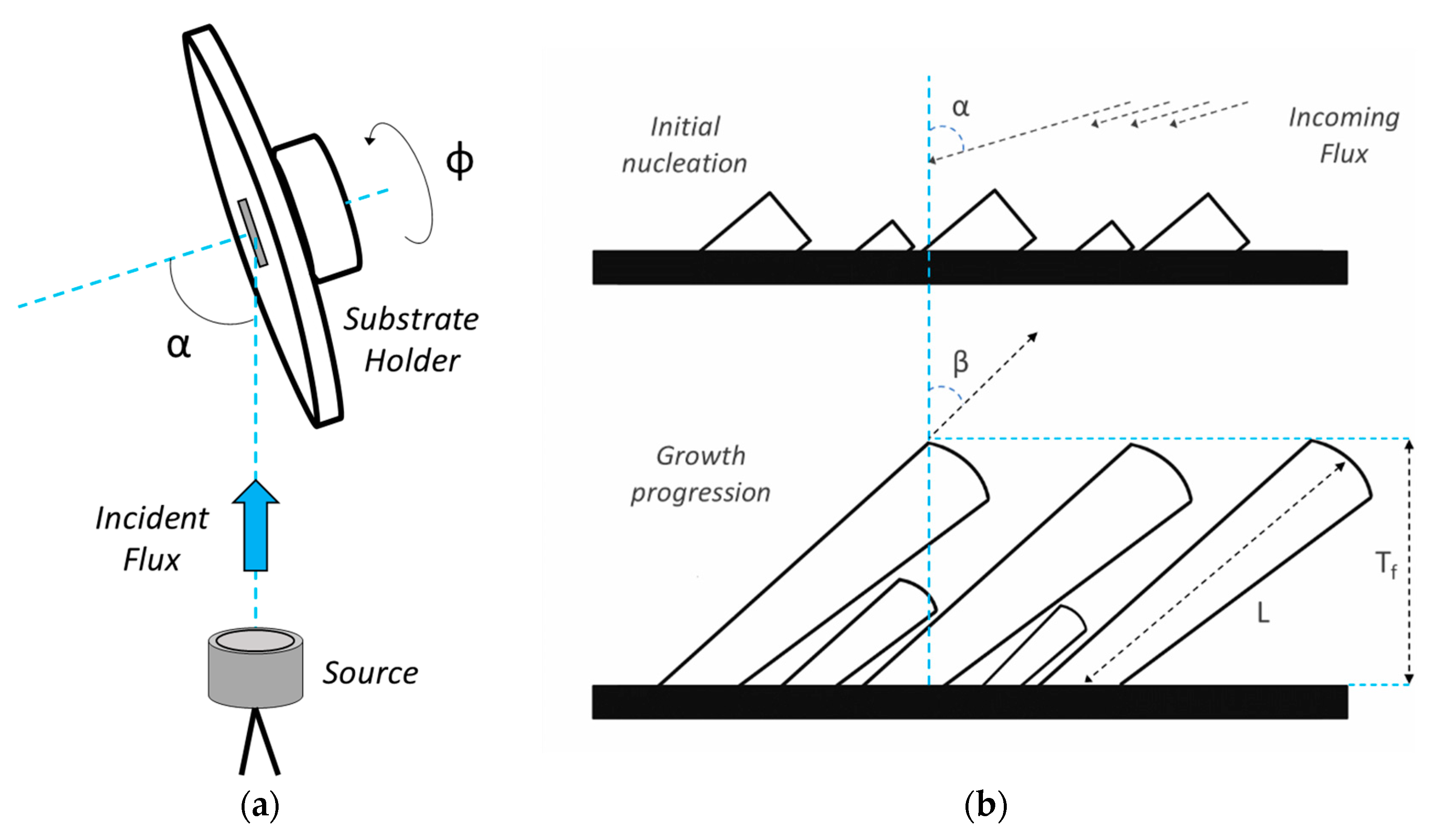
Figure 1. (a) Glancing angle deposition (GLAD) configuration showing incident flux angle, α, and rotation angle, φ, around the substrate normal. (b) Growth of nanocolumns with GLAD in Volmer–Weber growth mode illustrating growth progression, incident flux angle, α, column tilt angle, β, column length, L, and overall film thickness, Tf.
Coatings 10 00768 g001
Figure 2. (ad) Top-view and (eh) side-view scanning electron microscope (SEM) images of AlN nanocolumns grown at different working gas pressures. The average β angles measured from side-view images (eh) are 38°, 25°, 19°, and 5°, respectively. Initial and final β values of the nanocolumns are indicated at the bottom and top (respectively) in the side-view images (discussed in Section 3.1).
Coatings 10 00768 g002
Figure 3. Pole figures for AlN 0002 (ad) and 10 1 ¯ 0 (eh) grown with α = 85° at different working gas pressures with black arrows indicating direction of incoming flux.
Coatings 10 00768 g003
Figure 4. Plots showing AlN (0002) (a) peak full width at half maximum (FWHM) along ψ and φ and (b) peak intensity with corresponding polar position at different working pressures.
Coatings 10 00768 g004
Figure 5. Pole figures for AlN 0002 (ad) and 10 1 ¯ 0 (eh) grown with α = 0° at different working gas pressures with black arrows indicating the direction of incoming flux.
Coatings 10 00768 g005
Figure 6. X-ray diffraction (XRD) θ–2θ scans of AlN thin films at different working gas pressures.
Coatings 10 00768 g006
Figure 7. AlN 0002 pole figures for samples grown for 30 min at 1.5 mTorr using (a) GLAD and (b) normal deposition configuration with black arrows indicating the direction of incoming flux.
Coatings 10 00768 g007
Figure 8. Plot illustrating variation of AlN column and c-axis tilts for both growth configurations at different working gas pressures.
Coatings 10 00768 g008
Figure 9. Simulations showing average α of incoming metal flux when Al is sputtered using Ar (top) and N (bottom) at 10 (a,e), 5 (b,f), 3 (c,g), and 1.5 (d,h) mTorr working pressures in GLAD configuration. The dashed-line square in the maps represents position and (1 × 1 cm2) dimensions of the substrate while the gradient map represents a 5 × 5 cm2 area to visualize the behavior of transport of metal flux to and around the substrate. The maps are oriented such that the top edge of the map faces the Al source (not shown) placed 12 cm away from the dashed-line square (substrate).
Coatings 10 00768 g009
Figure 10. Simulations showing average E P of incoming particles when Al is sputtered using Ar (top) and N (bottom) at 10 (a,e), 5 (b,f), 3 (c,g), and 1.5 (d,h) mTorr working pressures in GLAD configuration. The dashed-line square in the maps represents position and (1 × 1 cm2) dimensions of the substrate while the gradient map represents a 5 × 5 cm2 area to visualize the behavior of the transport of metal flux to and around the substrate. The maps are oriented such that the top edge of the map faces the Al source (not shown) placed 12 cm away from the dashed-line square (substrate).
Coatings 10 00768 g010
Figure 11. Summary illustrating different AlN column lengths, average β angle (indicated on top of columns), and c-axis tilts (red lines represent c-planes) at different working gas pressures grown using GLAD configuration.
Coatings 10 00768 g011
Figure 12. Summary of (a) mean average total scattering angle and (b) mean average particle energy of simulated particles reaching the substrate after being sputtered using Ar (black) and N (red) at different working pressures in GLAD configuration. A range of total average scattering angle of the particles was simulated at different pressures and the mean of this averaged range was used to summarize the results in (a). Similarly, a range of average E P was simulated at different pressures and the mean of this averaged range was used to summarize results in (b).
Coatings 10 00768 g012
Figure 13. Illustrations of initial and final stages of AlN columnar film growth (with insets showing top-view SEM images of final column terminations and red lines representing c-axis tilt) at (a) 10 mTorr and (b) 1.5 mTorr.
Coatings 10 00768 g013
Figure 14. Summary of mean average number of simulated particles reaching the substrate after being sputtered using Ar (black) and N (red) at different working pressures in GLAD configuration.
Coatings 10 00768 g014
Figure 15. Illustration of dominant (i) and extinguished (ii, iii, iv, v, and vi) growth directions of AlN columns grown using GLAD.
Coatings 10 00768 g015