Article

Investigations in Anti-Impact Performance of TiN Coatings Prepared by Filtered Cathodic Vacuum Arc Method under Different Substrate Temperatures

1
Science and Technology on Plasma Dynamics Laboratory, Air Force Engineering University, Xi’an 710038, China
2
Cardiff School of Engineering, Cardiff University, Cardiff CF24 3AA, UK
*
Author to whom correspondence should be addressed.
Coatings 2020, 10(9), 840; https://doi.org/10.3390/coatings10090840
Submission received: 17 July 2020 / Revised: 21 August 2020 / Accepted: 25 August 2020 / Published: 28 August 2020

Abstract

:
In this study, the anti-impact performance of the TiN coatings prepared under various substrate temperatures (35, 200, 400, and 600 °C) were evaluated using a cyclic impact tester under 104 cycles. Moreover, the microstructure and anti-impact performance-related mechanical properties (adhesion strength and nano-hardness) were investigated to reveal the underlying mechanism of how the substrate temperature affects the anti-impact performance of the coatings. The results showed that the substrate temperature has a great influence on the internal stress, nano-hardness, and adhesion strength as well as the anti-impact performance of TiN coatings, and the coatings prepared under 400 °C exhibit the best impact resistance. The small internal stress, strong adhesion strength as well as high hardness and H3/E2 value for the 400 °C prepared coatings are the main contributes.

1. Introduction

Titanium alloy, such as Ti6Al4V, has been extensively used in the aviation and aerospace industries due to its excellent mechanical and physical properties [1,2]. However, its poor tribological behavior and low anti-erosion resistance could seriously limit its application [3,4]. To be more specific, the harsh serving conditions such as sandy and high-speed operations of the aeroengine compressor blades could cause prominent sand erosion damage on the inlet edge of these components. These erosion damage sites will act as the crack initiation origins, which will induce the failure of the fabricated components and pose serious threat to the flight safety [5,6]. In order to prolong the service life of these titanium alloy-fabricated components, the protective coatings deposited on the components’ surface is considered as a suitable choice [7,8,9,10]. With these protective coatings on the fabricated components surface, the sand induced impact and abrasion will not directly work on the components’ surface but on the coatings. As a result, the failure of the components can be slowed down in a certain degree. As for the anti-erosion resistance enhancement, TiN coatings have been demonstrated as one of most suitable coatings to resist sand erosion because of their inherently excellent mechanical and physical properties [11,12,13,14,15], including high hardness, strong adhesion, and dense microstructure.
In the past few decades, various deposition techniques have been employed to prepare TiN coatings, including magnetron sputtering [16], ion beam deposition [17], pulsed laser deposition [18], and cathodic arc deposition [19], etc. Being different from the above-mentioned deposition techniques, the coatings prepared via the magnetic filtered cathodic vacuum arc (FCVA) method have specific advantages, such as denser microstructure and stronger adhesion strength [20,21], which contribute to its excellent sand erosion resistance. Therefore, a lot of investigations about the use of the FCVA method for the deposition of TiN coatings have been made by our research group in the past several years [22,23,24,25,26]. For example, Zhang et al. [24] studied the multilayer structure’s sand erosion resistance of TiN coatings by the technique of FCVA with different TiN layers under the condition of the same total thickness. It was found that the TiN coatings with fewer TiN layers possess the more superior sand erosion resistance, benefiting from fewer vulnerable regions in coatings.
The sand erosion is a very complex process, which mainly consists of successive impacts by sand particles with different shape, size, impact energy, and impact angles [4,27,28]. In addition, under this high angle impact of injected solid particles, the TiN coatings with high hardness often could not resist sufficiently and easily fail in the form of brittle fracture due to the fact that the coatings exhibit lower toughness [26,27,29]. Hence, the anti-impact performance of TiN coatings is a key factor for the protective coatings from severe erosion damage. Moreover, extensive efforts have been devoted to improve the toughness of coatings, such as the optimization of structure and deposition parameters. Specifically, it has been demonstrated by Cao et al. [22] that the gradient multilayered structure of TiN/Ti coatings could decrease the degree of deformation mismatch between the hard and soft layers during the impact process, leading to the higher toughness and excellent sand erosion resistance for coatings. Moreover, Zhang et al. [25] revealed that the phase constituents and mechanical properties (the hardness and toughness) of TiN coatings can be optimized by adjusting the N2 flow rate, which ultimately have a great influence on the anti-sand erosion performance of TiN coatings.
Additionally, it has already been demonstrated that the substrate temperature could influence on the crystal structure and mechanical properties of the TiN coatings to a great extent which are prepared by other deposition methods [16,30,31]. For example, Subramanian et al. [30] have investigated the influence of substrate temperature on the microstructure and electrical properties of Ti/TiN films deposited by the DC reactive magnetron sputtering method and it was demonstrated that the conductivity of deposited Ti/TiN films depends on the substrate temperature. In addition, Kumar et al. [31] have studied the effect of substrate temperature on the grain size, hardness, and internal stress of Ni/TiN nanocomposite films prepared by magnetron co-sputtering. It was reported that the Ni-TiN films deposited under substrate temperature of 300 °C have the optimal synthesized properties of higher hardness and scratch resistance. However, as for the FCVA method, the effect of substrate temperature on the microstructure and mechanical properties of TiN coatings has rarely been studied. Hence, further investigations are needed to explore the influence of substrate temperature on the anti-impact performance of TiN coatings.
In this study, the anti-impact performance of the TiN coatings prepared under different substrate temperatures (35, 200, 400, and 600 °C) was quantitatively investigated using the cyclic impact tester, during which the dynamic response (impact velocity, impact force, and impact kinetic energy) of the impact block could be recorded. The microstructure and mechanical properties were investigated to explore the underlying mechanism of how the substrate temperature affects the anti-impact performance of the TiN coatings.

2. Materials and Methods

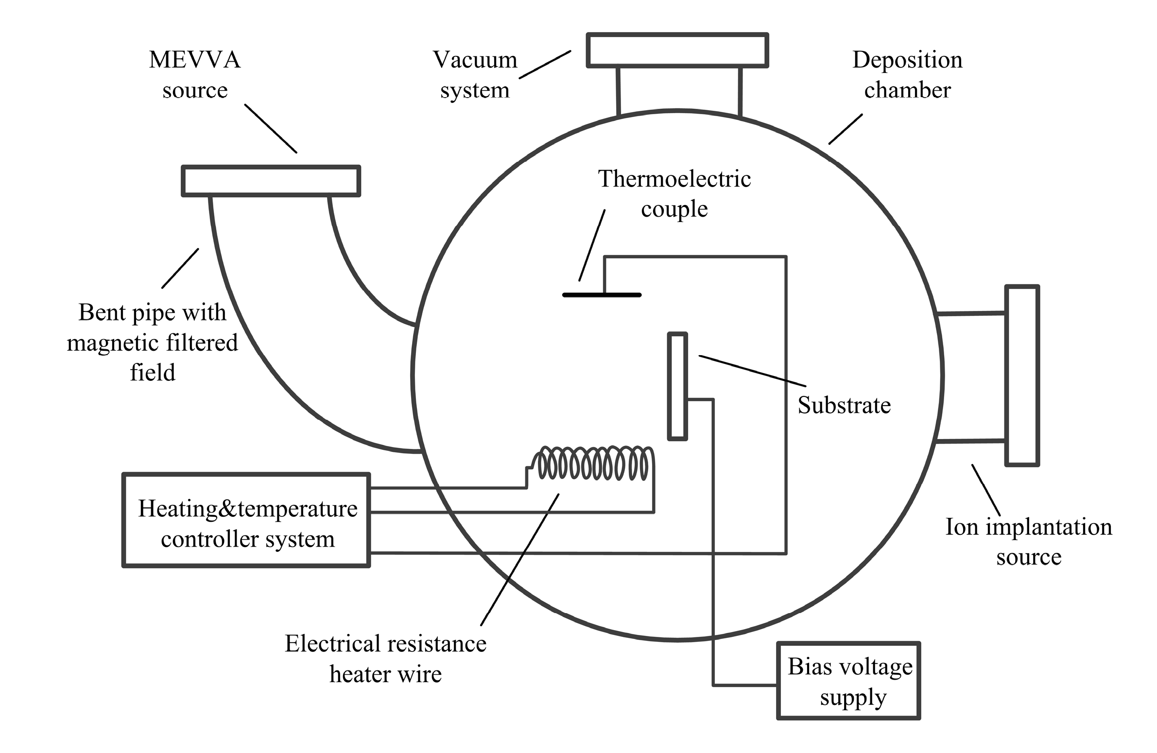
2.1. Coatings Preparation

The as-received Ti6Al4V titanium alloy plates were cut into specimens with the dimension of 50 × 20 × 3 mm as the substrate material to deposit the TiN coatings on. Prior to being fixed into the chamber, all the substrate top surfaces were grinded stepwise using the sandpaper ranging from #400 to #2000, followed by being polished with Al2O3 polishing paste (0.02 μm) until the substrate surface roughness was about 0.1 μm. Afterwards, all the samples were ultrasonically cleaned with acetone for 15 min and dried in the pure N2 atmosphere. As shown in Figure 1 [32], the coating deposition equipment mainly consists of ion implantation source and FCVA apparatus with a metal vapor vacuum arc (MEVVA) source. It should be noted that the ion implantation source here was used to improve the adhesion strength for TiN coatings [24,33].
The TiN coatings were prepared on the Ti6Al4V alloy under four different substrate temperatures (35, 200, 400, and 600 °C), and the corresponding specimens were denoted as Ts35, Ts200, Ts400, Ts600, respectively. It has to be mentioned that the substrate temperature was controlled by the heating and temperature controller system. In order to avoid excessive oxidation of the substrate specimens, the heating process was conducted when the vacuum chamber was evacuated to the pressure of 1.0 × 10⁻³ Pa. The deposition rate was ascertained according to the preliminary experiments (about 1 μm per 14 min) and the process preparation parameters for TiN coatings are summarized in Table 1.

2.2. Structural Characterization and Mechanical Performance Testing

To investigate the chemical bonding energy of the coatings, X-ray photoelectron spectroscopy (XPS) analysis was used in this study on a Thermo Fisher ESCALAB (ESCALAB 250Xi, Thermo Fisher, USA). Al K-Alpha radiation was operated at 320 W as the excitation source and the monochromator was used. In order to remove surface contamination, Ar+ ion etching was carried out for 120 s prior to the XPS analysis.
The crystal structure and internal stress of the coatings were studied by X-ray diffractometer (D8 ADVANCE, Bruker, Germany), in which the Cu Kα (λ = 0.154, 056 nm) radiation was operated under the working voltage of 40 kV and current of 40 mA. To eliminate the information disruption of substrate on TiN coatings, the grazing incident method with the incident angle of 2° was utilized. The range of 2θ was 20°–90° and the scan steps were 0.02° at the scanning speed of 2.45°/min. Furthermore, the cos2αsin2ψ method was used to calculate the internal stress of the coating with the constant incident angle of 2°. During the residual stress testing, the diffraction peaks (2θ = 77.913°) of TiN (220) were selected, which were measured at six inclination angles (ψ = 0, 9, 18, 27, 36, and 45°).
Surface morphologies of the coatings were observed by an atomic force microscope (INNOVA, Bruker, Germany). It has to be mentioned that the scanning area of the AFM is a square area with the dimension of 1 × 1 μm. The cross-sectional morphologies of the TiN coatings were observed by the scanning electron microscopy (VEGA3, TESCAN, Prague, Czech Republic).
The adhesion strength of the TiN coatings was measured using a scratch tester (Revetest, Anton Paar, Graz, Austria). The scratch tests were carried out with a Rockwell C diamond indenter. The scratch length of 5 mm with a loading rate of 80 N/min and scratch speed of 10 mm/min were applied. Moreover, the scratch morphologies were observed by the Optical Microscope (VHX-7000, KEYENCE, Shanghai, China). In order to reduce the measurement error, at least three scratches were made for each sample.
The nano-hardness and elastic modulus of the coatings were tested by Nano-Indenter (NanoTest Vantage, MML, London, UK) with a Berkovich indenter. In order to eliminate the influence of the substrate during the indentation, the indentation depth was set to less than 10% of the thickness of the coating for all the nanoindentation experiments. The maximum load, loading rate, and dwell time are 100 mN, 1 mN/s, and 5 s, respectively. Nine indentation sites were randomly selected to conduct the nanoindentation tests, and the average values of the hardness (H) and elastic modulus (E) were calculated by Oliver-Pharr’s method [34].

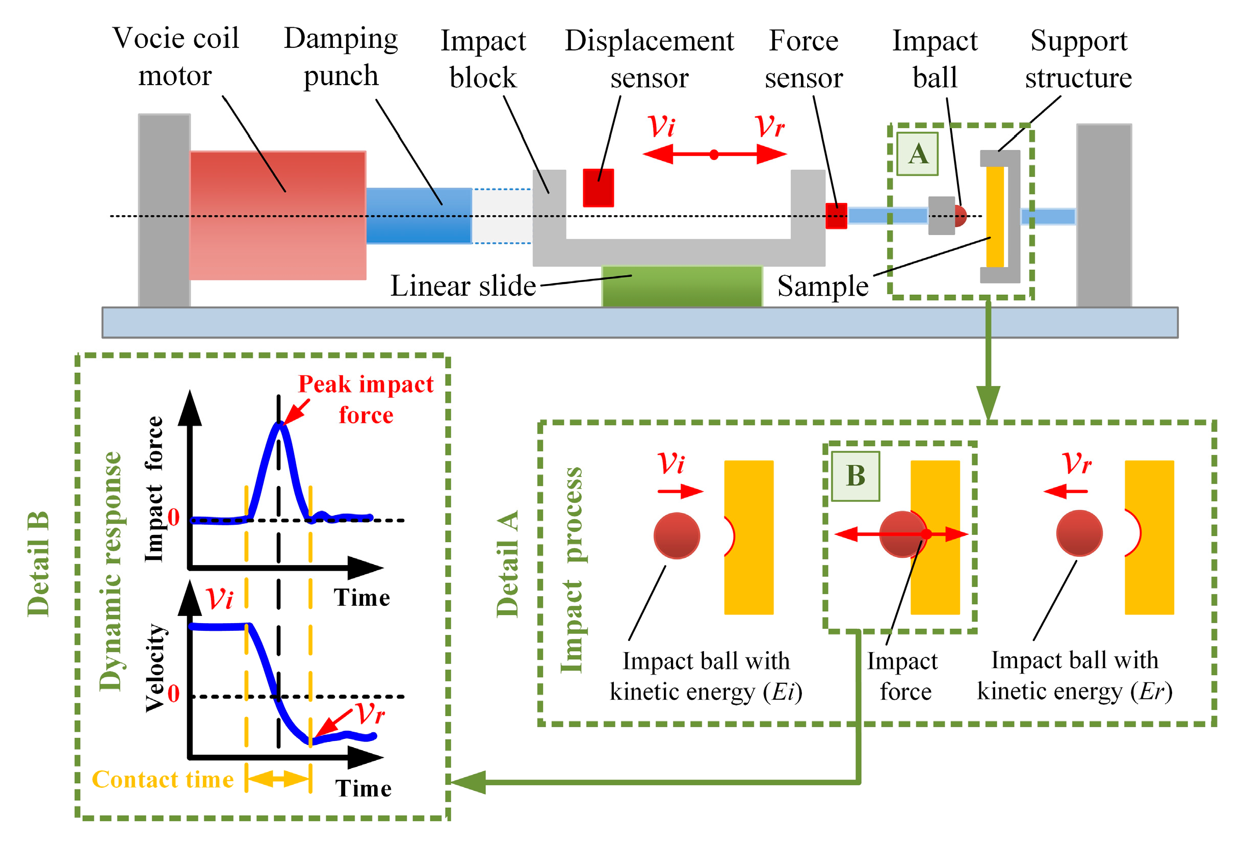
2.3. Cyclic Impact Experiment

In general, the weight loss rate of coatings during the erosion process is taken as the evaluation indicator for the anti-impact performance [8,27]. Nevertheless, the real-time impact effect of solid particles (i.e., impact force and impact energy) on the coatings surface can hardly be evaluated by the conventional erosion test. Hence, the information of dynamic impact response is needed to be investigated. Further, a cyclic impact tester with energy-control was developed to assess the impact response during each impact, which are realized by the sensors to record the information of impact force and impact energy [35,36,37]. In order to assess the impact resistance of the coatings, the impact cycles in this study were fixed at 104 cycles. From Figure 2, the impact effect in this tester is conducted by the impact block, which is driven by the coil motor. The impact process for each impact can be briefly concluded as follows: After the damping punch is motivated by the coil motor, the impact block will be driven next. When the speed of the impact block is accelerated to a certain velocity (νi), the impact block will continue to run a nearly uniform motion to impact the coating sample, due to the negligible friction force of linear guide and the fact that the damping punch is separated from the impact block. The impact ball installed located on the impact block will impact the coatings surface on a freely process, and after the impacting process, the impact ball will be rebounded with a separated velocity (νr), and reconnected with the damping punch for the next impact. In this study, the Si3N4 ceramic ball with the diameter of 2.38 mm was chosen as the impact ball, the mass of the impact block (m) was 252.5 g, and the speed was 120 mm/s. Each experiment was repeated three times. The impact morphologies on the TiN coatings were observed by the scanning electron microscopy (VEGA3, TESCAN, Prague, Czech Republic) at the magnification of 500× and 1500×.
Moreover, the working principle of this cyclic impact tester is as follows: The normal impact process on the sample surface was conducted by the hard ball, which is to simulate the successive sand particles impacts from a normal angle during the real erosion process. It is worth noticing that the simulation of the ball impacts could simplify the complex sand impacts with different sizes and shapes of particles via controlling the impact energy of impact block. The contact force was recorded by the force sensor, nominally as the impact force, which was induced by the contact between the impact ball and sample. Moreover, the kinetic energy of impact block was calculated with the velocity of impact block during each impact, which was recorded by the displacement sensor. In order to further reveal the working principles of the impact devices, two detailed schematic diagrams were added to Figure 2. As shown in the detailed A diagram, the impact ball, which was installed on the impact block, was accelerated to a certain initial velocity to conduct the impact process. During the specific contact process, the impact ball with the initial kinetic energy (Ei) will reduce the impact interaction between the impact ball and sample surface. Subsequently, the impact block will be rebounded with a separated velocity (νr), and the rebound kinetic energy (Er) could be calculated according to the separated velocity (νr). It has to be declared that there was a kinetic energy loss during the impact process, which is mainly consumed for the materials deformation [38]. To clarify the dynamic response during the impact process, the detailed B diagram was also added. As shown in this diagram, the impact force will increase to the maximum value (peak impact force) from zero and then decrease to zero again. Correspondingly, the velocity of the impact block will reduce to zero firstly and subsequently increase to a certain value, which is less than the initial velocity due to the energy loss during impacts.

3. Results

3.1. Anti-Impact Performance
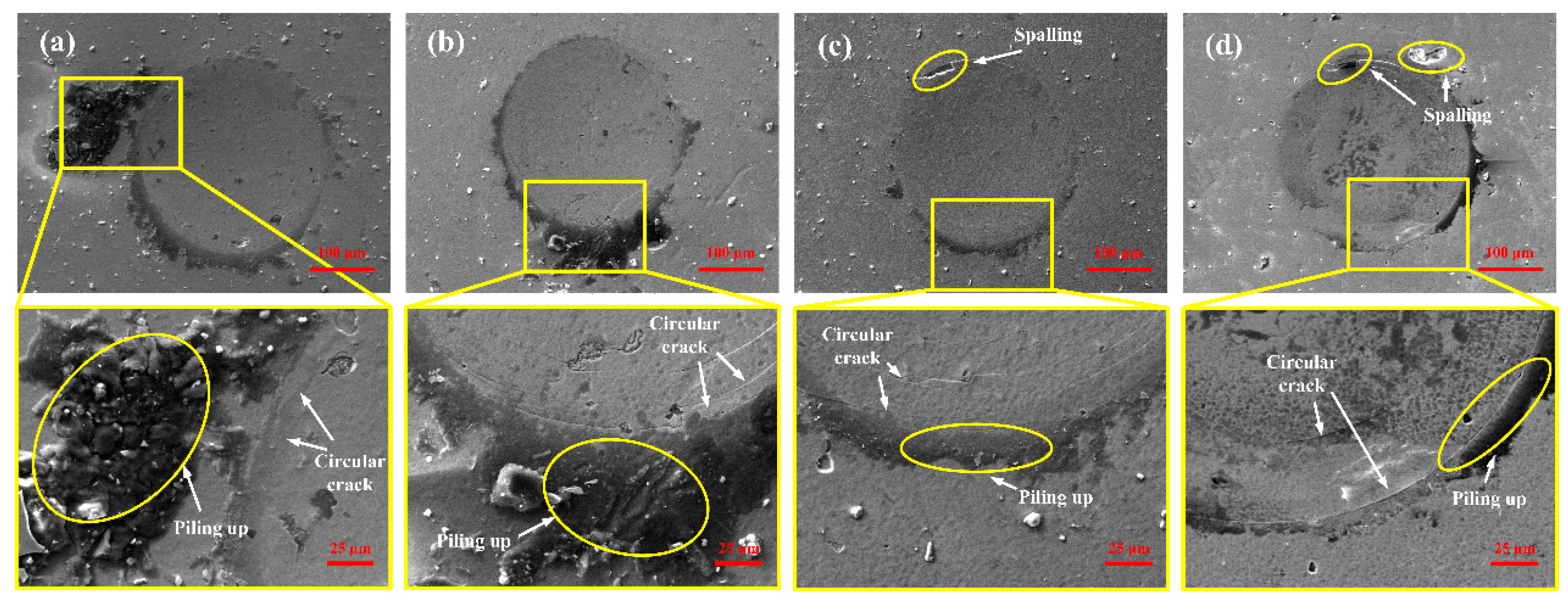
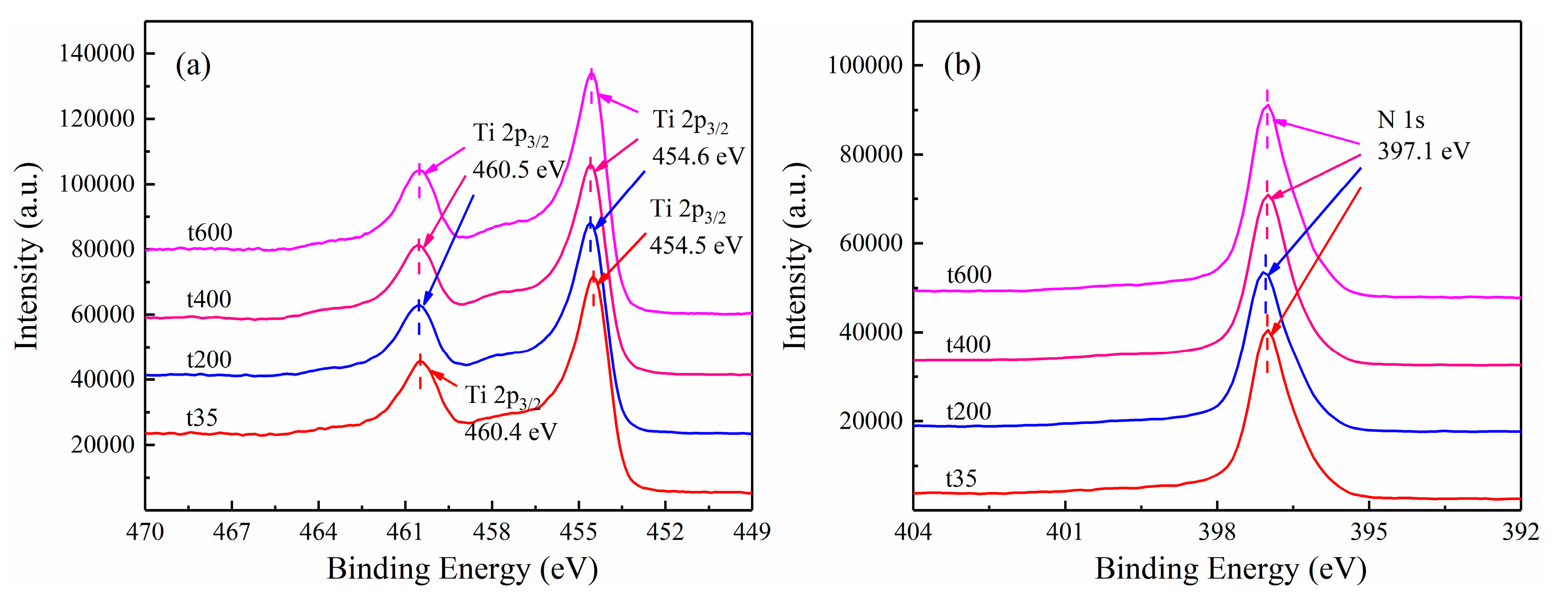
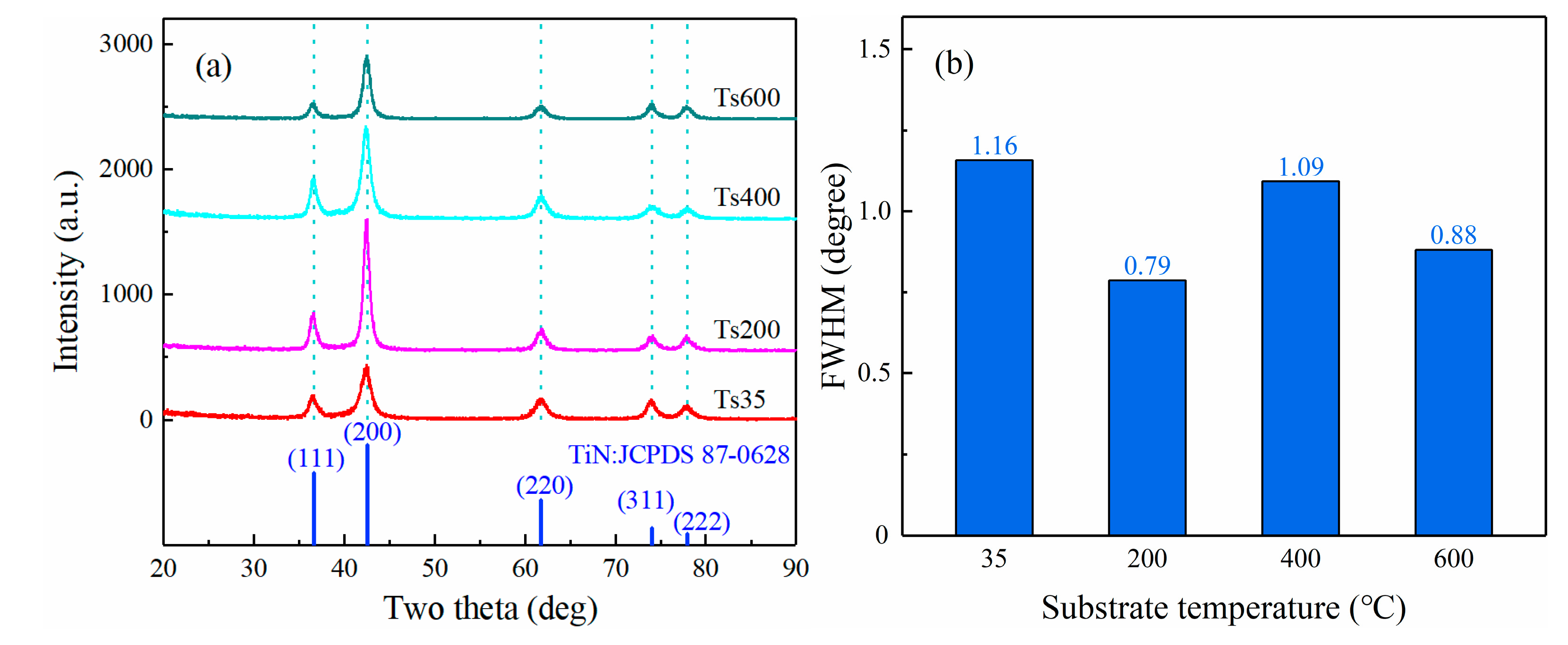
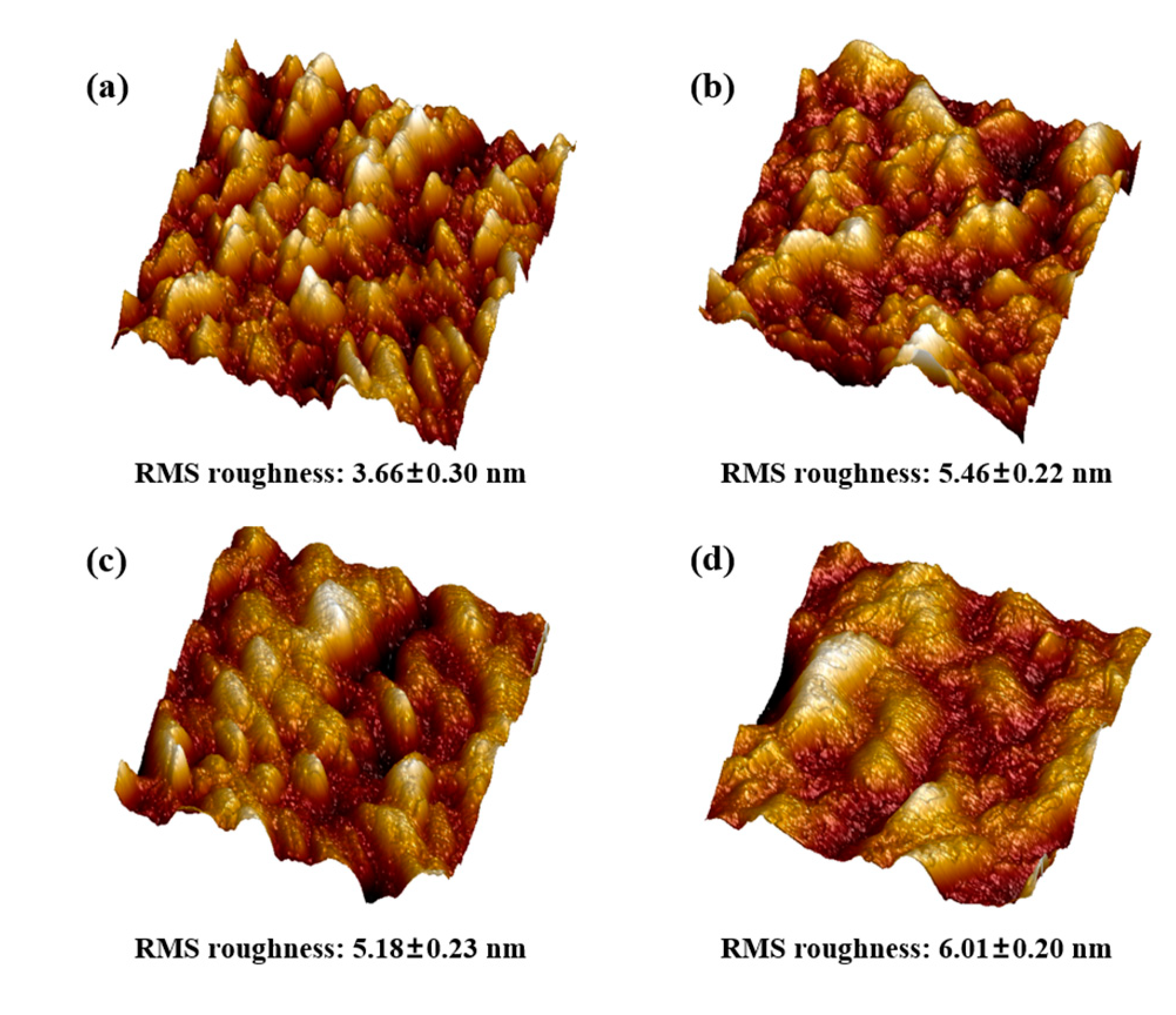
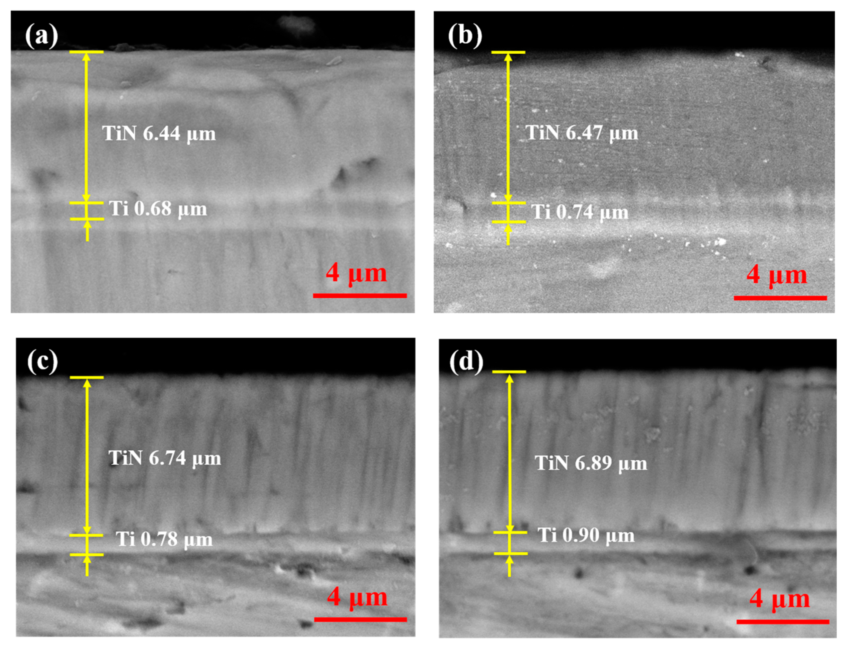
The same cyclic impact conditions with the initial impact energy were applied. According to the kinetic energy formula, the initial kinetic energy (Ei) is 1.818 mJ and the rebound kinetic energy (Er) could be calculated according to the separated velocity (νr). It has to be mentioned that the energy absorption rate (σ) was calculated by the following formula:
σ = E i E r E i
Figure 3a,b shows the impact force and impact kinetic energy evolution versus contact time during the 10th impact for TiN coatings prepared under different temperatures, and their peak impact force and energy absorption rate were extracted (as shown in Figure 3c). As shown in Figure 3a, during the impact process, the curve of impact force versus contact time looks similar to a sinusoidal curve. The impact force reaches a peak value when the coating experiences the maximum plastic deformation. Then, the impact force drops to zero when the impact ball is separated from the coating surface totally. It can be seen from Figure 3a that there was a negligible difference for the contact time among different TiN coatings, which is from 0.53 to 0.55 ms. In addition, the dissipation of impact kinetic energy of the impact block was observed in Figure 3b, and it can be found that the impact kinetic energy decreased sharply during the whole impact process compared to the initial value of 1.818 mJ. Moreover, as shown in Figure 3c, the peak impact force and energy absorption rate show the same trend with the substrate temperatures variation. Specifically, it firstly decreases, then increases and the temperature of 400 °C is the inflection point, which indicates the best anti-impact performance. The high hardness and toughness of the coatings, which can be influenced by the substrate temperature in the course of deposition, were the attributes for the lower peak impact force [38]. Moreover, it has already been demonstrated by He et al. [38] that the energy absorption rate is related to the plastic deformation resistance, and the lowest absorption rate for TiN coatings prepared under 400 °C exhibits the best anti-impact resistance.
Further, to study the impact damage behavior of different coatings, the corresponding impact morphologies have been investigated via the scanning electron microscopy. The morphologies of these impact pits on different coating surfaces were observed, as shown in Figure 4. Correspondingly, the enlarged view was also displayed in Figure 4. From the perspective of qualitative analysis, there were three typical damage behaviors, including circular cracks, piling up, and spalling. Interestingly, the circular cracks can be found on the periphery of all the coating surfaces, which are attributed to the tensile stress during the cyclic impact [23,39], but the piling up [39,40] and spalling [26,36,40] are different for TiN coatings prepared under different substrate temperatures, where the large area of piling up around the pits occurs at the Ts35 and Ts200 coatings, while the spalling of pits can be only found for the TiN coatings under 400 and 600 °C, especially for the Ts600 coatings. From the above-reported results, it is clear that the substrate temperature has a significant influence on the anti-impact performance for TiN coatings, and the excellent anti-impact performance is obtained for the Ts400 coatings. According to the literature, the anti-impact performance is related to the microstructure and mechanical properties [40,41,42]. Hence, these microstructure and mechanical properties were investigated further in the next section.

3.2. Microstructure

It was reported that the binding energy of the atomic bonds for titanium and nitrogen elements has a significant influence on the phase and mechanical properties of TiN coatings [25]. Therefore, in this part, the XPS was employed to investigate the binding energies of the coatings prepared under different substrate temperatures, whose results are shown in Figure 5. First of all, it has to be declared that the C 1 s spectrum (BE value of 284.8 eV) from adventitious carbon was conducted for energy referencing of the XPS spectra. Surprisingly, it can be seen from Figure 5a,b that there is negligible difference in the position and intensity of these peaks corresponding to the Ti 2p and N 1s on these TiN coatings, indicating that the substrate temperature almost has no influence on the binding energies of the Ti and N atoms.
Although the binding energy has little difference on the TiN coatings under different substrate temperatures, the phase structure may be influenced by the substrate temperature, which could affect the anti-impact performance [26]. Therefore, the XRD patterns of TiN coatings prepared under different substrate temperatures are shown in Figure 6a. It was found that there were five representative diffraction peaks on the TiN coatings which were identified as (111), (200), (220), (311), and (222) of TiN phase according to the TiN card (JCPDS87-0628) and no new peaks were observed for all the cases. Moreover, the three peaks of (220), (311), and (222) located at higher degree show a slight difference in peak intensity, and no shifting and widening of peaks were found. Nevertheless, these changes are obvious for the lower degree peaks of (111) and (200). In particular, when the substrate temperature increased from 35 to 600 °C, the intensity for the peak of (200) firstly shows a significant increase, but then it started to decrease from the point of 200 °C. However, it is still higher than those of TiN prepared under 35 °C. Further, the full width at half maximum (FWHM) of the (200) peaks of these coatings was calculated, as shown in Figure 6b, it can be seen that the FWHM values of the (200) peak on different coatings show a nonlinear trend. According to the Scherrer formula, it can be said that the higher substrate temperature can increase the grain size, which can be explained by the fact that the higher substrate temperature could promote the mobility of the atoms, hence further enhancing the nucleation and agglomeration of crystallites [30].
Figure 7 shows the surface morphology and roughness (root-mean-square, RMS) of the as-deposited coatings, investigated by the atomic force microscope (1 × 1 μm). The RMS values of all coatings were less than 10 nm. Moreover, it can be seen that there is a nonlinear relationship between the roughness evolution and substrate temperature. Particularly, as the substrate temperature increased from 35 to 600 °C, the trend of roughening was clear, and the hills-like structure became rougher and nonuniform, especially in Ts600 coatings, which may be related to the larger grain size caused by the higher temperature [30].
The cross-sectional morphologies of the TiN coatings were observed by the scanning electron microscopy, as shown in Figure 8. It can be found that the thickness of TiN layers and Ti layers all show a slowly increased tendency as the substrate temperature evaluated, which may be influenced by the enhanced atoms diffusion and increased crystallite size with the higher substrate temperature [18].

3.3. Mechanical Properties

As the results of XPS and XRD were shown above, there were negligible differences on the microstructure of TiN coatings under different substrate temperatures. The mechanical properties are also proved to have a significant influence on the anti-impact performance [40,41]. Hence, the mechanical properties, consist of residual stress, and adhesion strength and the nano-hardness of these TiN coatings will be shown in the following parts.
Residual stress distribution on the TiN/Ti coating surface prepared under different substrate temperatures was measured by the XRD using the side-inclination method, as shown in Figure 9. It can be seen that the surface residual stresses on all the coatings are compressive. This can be attributed to the fact that the atomic peening effect during the deposition process could induce the lattice distortion and compressive residual stress on the coating [43]. To be more specific, when the substrate temperature increases from 35 to 400 °C, the residual stress shows a continuous decline. However, when the substrate temperature comes to 600 °C, the surface residual stress is higher than that of the coatings under the circumstance of 400 °C. The decreased residual stress caused by the temperature increase is due to the fact that the increased temperature could promote the flow of the atoms, as a result, the bound atoms have more energy to escape from the non-equilibrium state to a balance position where they tend to move, which will release the stress inside the coating [44]. However, the excessive substrate temperature (600 °C) may result in a negative effect, which is caused by the enhanced thermal stress generated for the difference in thermal expansion coefficients of the coating and the substrate [45]. Therefore, selecting an appropriate substrate temperature is a key step for the property’s optimization of the coatings.
The adhesion strength, which can be evaluated via the scratch test, of the prepared coatings is an important indicator for the coatings [46]. In this study, the critical loads (LC3) being exploited during the scratch test were adopted to assess the adhesion strength for different coatings according to these literatures [47,48]. The LC3 is the transient load when the first delamination occurs between the coatings and substrate, which could be observed from the scratch morphologies [49]. The scratch morphologies of these TiN coatings were shown in Figure 10, and the LC3 of each coating is marked by the red arrow. Obviously, the evolution of the adhesion strength of these coatings show a similar trend with the residual stress. The evolution of the adhesion strength with the substrate temperature change was the combined results from the atomic diffusion and crystallization as well as the mismatched thermal stress. When the substrate temperature is increased, the atomic diffusion and crystallization are intensive and strengthened [50], leading to an increase in the adhesion strength. In addition, thermal stresses that originated from a severe mismatch between the coating and the substrate under much higher temperature (600 °C) were attributed to the weakened adhesion strength. These results indicate that the substrate temperature could affect the adhesion strength to a great extent, and the optimal substrate temperature is 400 °C.
Figure 11 displays the nano-hardness, elastic modulus, and H3/E2 value of TiN coatings prepared under different substrate temperatures. It can be seen from Figure 11a that both the hardness and elastic modulus of these coatings show a first increased and then decreased trend. The inflection points of these two values correspond to the temperature of 400 °C, and the corresponding hardness and elastic modulus were measured to be 30.2 ± 2.7 and 280.8 ± 8.5 GPa, respectively. This change of hardness may be attributed to the combined effect of grain size and microstructure. The grain size of TiN coatings increased with the substrate temperature evaluated, which could result in the decrease of hardness [18]. However, the hardness is enhanced instead from 35 to 400 °C, which exhibits an opposite trend. The enhanced hardness may be attributed to the fact that the microstructure will become denser when the substrate temperature is evaluated, which could lead to the increase of hardness [51]. In addition, the hardness influenced by the dense microstructure is the prominent effect for the hardness of coatings from 35 to 400 °C. Consequently, the hardness reaches the highest value under substrate temperature of 400 °C.
Furthermore, to qualitatively evaluate the toughness of as-deposited coatings, the indicator of H3/E2 was widely used to evaluate the resistance to plastic deformation [52,53,54]. The higher H3/E2 value of the coatings, the stronger the ability to resist plastic deformation. Figure 11b shows the H3/E2 value of TiN coatings prepared under different substrate temperatures. Interestingly, the H3/E2 value has the similar tendency with nano-hardness and elastic modulus as well as the adhesion strength, and it peaks at the temperature of 400 °C.

4. Discussion

From the above-reported results, it has been demonstrated that the substrate temperature has a significant influence on the anti-impact performance of the TiN coatings. With respect to the dynamic response results of these coatings (Figure 3), the peak impact force and energy absorption rate do not show a monotonous variation but a firstly increase and then decrease trend with the evolution of the substrate temperature. In particular, the substrate temperature of 400 °C is the inflection point, in which the peak impact force and energy absorption rate reach the lowest values of 173 N and 79.6%, respectively. The lowest peak impact force and energy absorption rate means the best anti-impact performance of the TiN coatings prepared under this certain substrate temperature. According to the literature [26], Zhang et al. indicated that the anti-impact performance is affected by the synthesized effects of hardness and toughness. Moreover, according to He’s interpretation [38], the TiN coatings with the highest H3/E2 value exhibit the highest plastic deformation resistance, leading to the lowest energy absorption rate. In this study, as shown in Figure 11a,b, the coating prepared under 400 °C exhibited the highest hardness and H3/E2 value, the reported result is consistent with Zhang’s findings [26]. Therefore, it can be said that the highest hardness and H3/E2 value for the coatings prepared under 400 °C in this study are the main contributes for the lower impact damage with respect to the dynamic response.
Additionally, from the impact morphologies of these coatings after the impact test (shown in Figure 4), it can be found that there are three main characteristic damage features, including circular cracks, piling up, and spalling on the sample surface, which reflect different mechanisms experienced during the impact process. To be more specific, the circular cracks on the periphery of impact pits are caused by the tensile stress during the cyclic impact [23,39]. The piling up around the impact pits was formed by the accumulated debris in the course of impact, which is attributed to the severe deformation and removal of surface materials [26,39,40,55]. Additionally, the spalling is due to the cyclic shearing stress in the subsurface of coatings, which could induce the initiation and propagation of cracks [36,40,56]. It has to be noted that spalling mainly occurs at the edge of the scar [36]. A large number of piling up and relatively small number of circular cracks around the impact pits were found on the surface of the Ts35 and Ts200 coatings (shown in Figure 4a,b), which is caused by the relatively soft coatings with lower hardness and lower H3/E2 value. It has to be mentioned that the extensive piling up for the Ts35 and Ts200 coatings is caused by the severe plastic deformation during the impact process. Being different from the Ts35 and Ts200 coatings, the slight piling up for the Ts400 and Ts600 coatings are attributed to the enhanced hardness as well as the higher H3/E2 value, which could reduce the plastic deformation occurrence. As the cyclic impact process is a very complex process, and the fatigue damage could be induced during the repeated impact process [42], the Ts600 coatings, which process a lower adhesion strength and higher internal stress, is vulnerable to spall and forms a larger scale of spalling on the peripheral area when subjected to tensile stress during the cyclic impacts (shown in Figure 4d). As for the TiN coatings prepared under 400 °C, a small number of piling up and spalling were found, which indicates the best anti-impact performance of the coating. The highest hardness and H3/E2 value of coatings prepared under 400 °C should play the dominating role.
In summary, it can be concluded that the TiN coatings prepared under 400 °C exhibit the best anti-impact performance using the FCVA method, which result from the combined effects of the small internal stress, the strong adhesion strength as well as high hardness and H3/E2 value.

5. Conclusions

In this study, TiN coatings were prepared on the Ti6Al4V titanium alloy substrate using the FCVA method with various substrate temperatures. The microstructure and mechanical properties of different TiN coatings were investigated and compared. Finally, the impact resistance of these as-deposited coatings was evaluated by the cyclic impact tester. The results show that the substrate temperature has a significant influence on the anti-impact performance and mechanical properties of the TiN coatings. Some specific results can be concluded as follows:
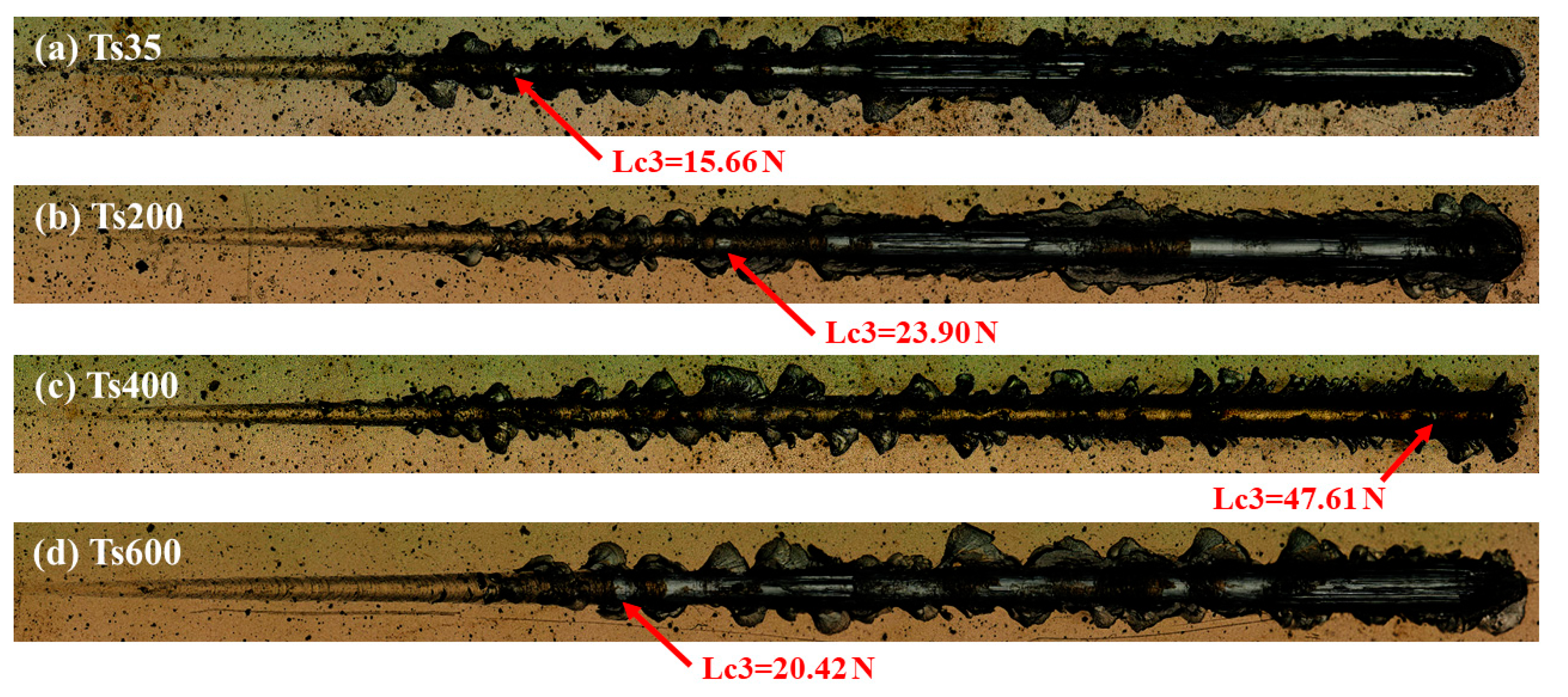
  • With the change of the substrate temperature from 35 to 600 °C, the adhesion strength and nano-hardness show the same trend (firstly increase and then decrease), and they peak at the substrate temperature of 400 °C, which is 47.61 N and 30.2 ± 2.7 GPa, respectively.
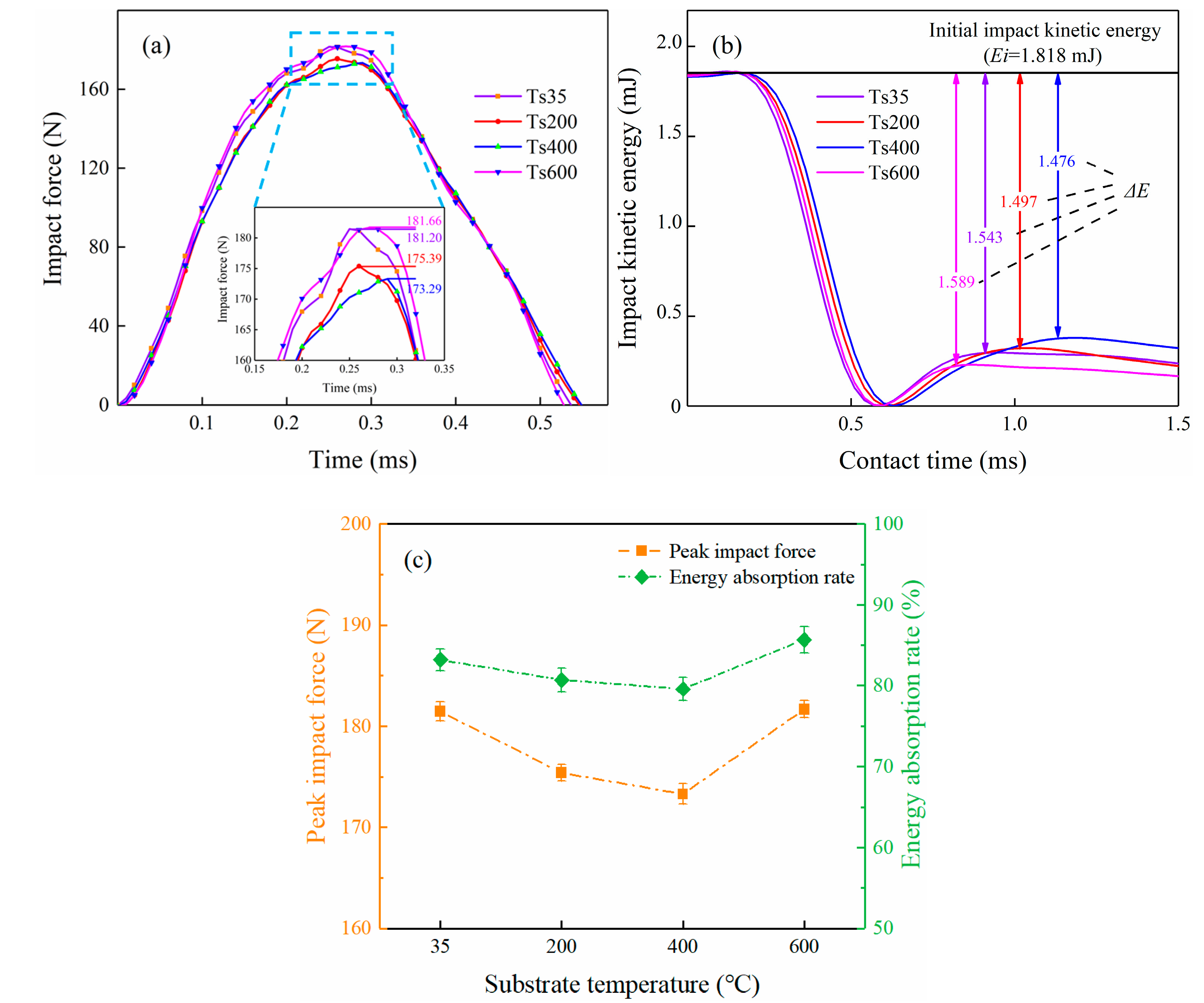
  • The TiN coatings prepared under the 400 °C show the best impact resistance performance with the lowest peak impact force (173 N) and energy absorption rate (79.6%).
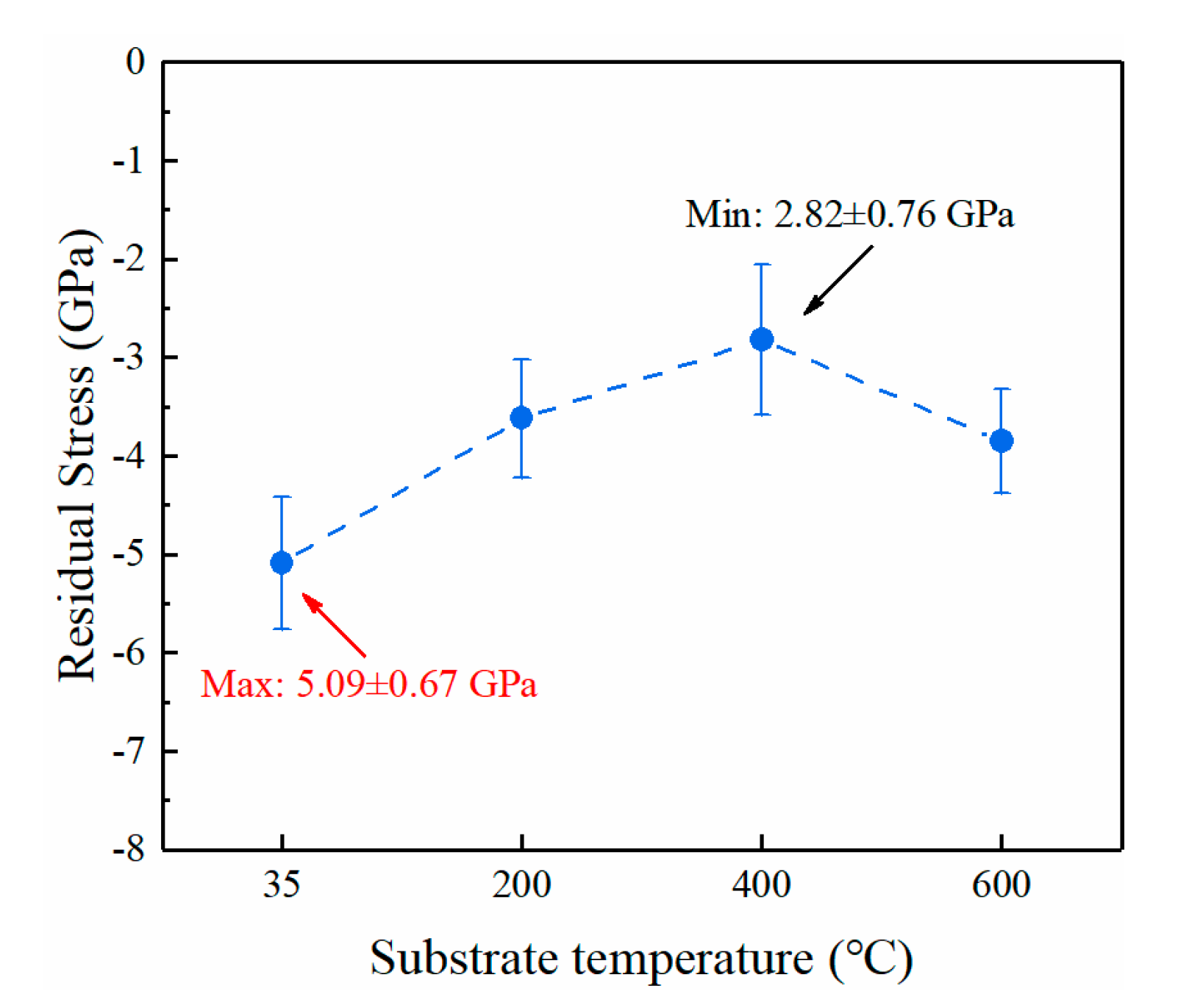
  • The evolution of the substrate temperature has a negligible effect on the microstructure of the TiN coatings. Therefore, it is deduced that the best impact resistance of the coatings is attributed to the small internal stress, strong adhesion strength as well as high hardness and H3/E2 value.
All in all, it can be concluded from this study that the substrate temperature is an important coating deposition parameter, and for the specific TiN coatings, 400 °C is suitable for the investigated parameters. The results in this study further demonstrate the significant effect of substrate temperature on the anti-impact performance of TiN coatings. The results lay some foundations for the deposition parameters optimization on the purpose of anti-impact performance enhancement for TiN coatings.

Author Contributions

Conceptualization, X.C.; investigation, D.H.; methodology, Y.J.; project administration, W.H.; writing—original draft, D.H.; writing—review and editing, D.H. and Y.J. All authors have read and agreed to the published version of the manuscript.

Funding

This research was funded by the National Science and Technology Major Project (2017-VII-0003-0096 and 2017-VII-0012-0107).

Acknowledgments

The College of Nuclear Science and Technology at Beijing Normal University supported the coating deposition facilities.

Conflicts of Interest

The authors declare no conflict of interest.

References

  1. Yumak, N.; Aslantas, K.; Pekbey, Y. Effect of cryogenic and aging treatments on low-energy impact behaviour of Ti–6Al–4V alloy. Trans. Nonferr. Met. Soc. 2017, 27, 514–526. [Google Scholar] [CrossRef]
  2. Wu, Z.H.; Kou, H.C.; Tang, B.; Fan, J.K.; Chen, Y.; Li, J.S. Stress relaxation induced morphological evolution and texture weakening of α phase in Ti-6Al-4V alloy. Mater. Lett. 2019, 236, 148–151. [Google Scholar] [CrossRef]
  3. Selivanov, K.S.; Smyslov, A.M.; Dyblenko, Y.M.; Semenova, I.P. Erosive wear behavior of Ti/Ti(V,Zr)N multilayered PVD coatings for Ti-6Al-4V alloy. Wear 2019, 418–419, 160–166. [Google Scholar] [CrossRef]
  4. Tortuero, S.; Garrido, M.A.; Poza, P.; Rodríguez, J. Evaluating the erosion resistance of Ti6Al4V coatings deposited by cold spray. Wear 2020, 454–455, 203337. [Google Scholar] [CrossRef]
  5. Bonu, V.; Jeevitha, M.; Praveen Kumar, V.; Barshilia, H.C. Nanolayered multilayer Ti/TiN coatings: Role of bi-layer thickness and annealing on solid particle erosion behaviour at elevated temperature. Surf. Coat. Technol. 2019, 357, 204–211. [Google Scholar] [CrossRef]
  6. Yang, Q.; McKellar, R. Nanolayered CrAlTiN and multilayered CrAlTiN–AlTiN coatings for solid particle erosion protection. Tribol. Int. 2015, 83, 12–20. [Google Scholar] [CrossRef]
  7. Deng, J.; Wu, F.; Lian, Y.; Xing, Y.; Li, S. Erosion wear of CrN, TiN, CrAlN, and TiAlN PVD nitride coatings. Int. J. Refract. Met. Hard Mater. 2012, 35, 10–16. [Google Scholar] [CrossRef]
  8. Chen, J.; Zhang, Z.; Yang, G.; Fang, Z.; Yang, Z.; Li, Z.; He, G. Performance and damage mechanism of TiN/ZrN nano-multilayer coatings based on different erosion angles. Appl. Surf. Sci. 2020, 513, 145457. [Google Scholar] [CrossRef]
  9. Lin, S.; Zhou, K.; Dai, M.; Lan, E.; Shi, Q.; Hu, F.; Kuang, T.; Zhuang, C. Structural, mechanical, and sand erosion properties of TiN/Zr/ZrN multilayer coatings. Vacuum 2015, 122, 179–186. [Google Scholar] [CrossRef]
  10. Todt, J.; Pitonak, R.; Köpf, A.; Weißenbacher, R.; Sartory, B.; Burghammer, M.; Daniel, R.; Schöberl, T.; Keckes, J. Superior oxidation resistance, mechanical properties and residual stresses of an Al-rich nanolamellar Ti0.05Al0.95N coating prepared by CVD. Surf. Coat. Technol. 2014, 258, 1119–1127. [Google Scholar] [CrossRef]
  11. Bonu, V.; Jeevitha, M.; Kumar, P.V.; Bysakh, S.; Barshilia, H.C. Ultra-thin multilayered erosion resistant Ti/TiN coatings with stress absorbing layers. Appl. Surf. Sci. 2019, 478, 872–881. [Google Scholar] [CrossRef]
  12. Borawski, B.; Todd, J.A.; Singh, J.; Wolfe, D.E. The influence of ductile interlayer material on the particle erosion resistance of multilayered TiN based coatings. Wear 2011, 271, 2890–2898. [Google Scholar] [CrossRef]
  13. Feuerstein, A.; Kleyman, A. Ti–N multilayer systems for compressor airfoil sand erosion protection. Surf. Coat. Technol. 2009, 204, 1092–1096. [Google Scholar] [CrossRef]
  14. Reedy, M.W.; Eden, T.J.; Potter, J.K.; Wolfe, D.E. Erosion performance and characterization of nanolayer (Ti,Cr)N hard coatings for gas turbine engine compressor blade applications. Surf. Coat. Technol. 2011, 206, 464–472. [Google Scholar] [CrossRef]
  15. Sundgren, J.E. Structure and properties of TiN coatings. Thin Solid Films 1985, 128, 21–44. [Google Scholar] [CrossRef]
  16. Vasu, K.; Krishna, M.G.; Padmanabhan, K.A. Substrate-temperature dependent structure and composition variations in RF magnetron sputtered titanium nitride thin films. Appl. Surf. Sci. 2011, 257, 3069–3074. [Google Scholar] [CrossRef]
  17. Liang, W.; Ling, Y.; Liu, K.; Hu, Y.; Yin, A.; Zhu, F.; Chen, L.; Zhang, Z. Corrosion resistance and mechanism of CeN, TiN and CeN/TiN bilayer composite film deposited by dual ion beam sputtering. Surf. Coat. Technol. 2018, 335, 280–287. [Google Scholar] [CrossRef]
  18. Guo, H.; Chen, W.; Shan, Y.; Wang, W.; Zhang, Z.; Jia, J. Microstructures and properties of titanium nitride films prepared by pulsed laser deposition at different substrate temperatures. Appl. Surf. Sci. 2015, 357, 473–478. [Google Scholar] [CrossRef]
  19. Ravi, N.; Markandeya, R.; Joshi, S.V. Effect of substrate roughness on adhesion and tribological properties of nc-TiAlN/a-Si3N4 nanocomposite coatings deposited by cathodic arc PVD process. Surf. Eng. 2017, 33, 7–19. [Google Scholar] [CrossRef]
  20. Vereschaka, A.A.; Vereschaka, A.; Batako, A.; Mokritskii, B.; Aksenenko, A.; Sitnikov, N. Improvement of structure and quality of nanoscale multilayered composite coatings, deposited by filtered cathodic vacuum arc deposition method. Nanomater. Nanotechnol. 2017, 7, 1–13. [Google Scholar] [CrossRef] [Green Version]
  21. Shulepov, I.; Kashkarov, E.; Stepanov, I.; Syrtanov, M.; Alina, S.; Shanenkov, I.; Obrosov, A.; Weiss, S. The formation of composite Ti-Al-N coatings using filtered vacuum arc deposition with separate cathodes. Metals 2017, 7, 497. [Google Scholar] [CrossRef] [Green Version]
  22. Cao, X.; He, W.; Liao, B.; Zhou, H.; Zhang, H.; Tan, C.; Yang, Z. Sand particle erosion resistance of the multilayer gradient TiN/Ti coatings on Ti6Al4V alloy. Surf. Coat. Technol. 2019, 365, 214–221. [Google Scholar] [CrossRef]
  23. Cao, X.; Xu, W.; He, W. A method for evaluating the impact wear behavior of multilayer TiN/Ti coating. Coatings 2020, 10, 132. [Google Scholar] [CrossRef] [Green Version]
  24. Zhang, H.; Li, Z.; He, W.; Liao, B.; He, G.; Cao, X.; Li, Y. Damage evolution and mechanism of TiN/Ti multilayer coatings in sand erosion condition. Surf. Coat. Technol. 2018, 353, 210–220. [Google Scholar] [CrossRef]
  25. Zhang, H.; Li, Z.; Ma, C.; He, W.; Cao, X.; Li, Y. The anti-sand erosion performance of TiN films fabricated by filtered cathodic vacuum arc technique at different nitrogen flow rates. Ceram. Int. 2019, 45, 10819–10825. [Google Scholar] [CrossRef]
  26. Zhang, H.; Li, Z.; He, W.; Ma, C.; Liao, B.; Li, Y. Mechanical modification and damage mechanism evolution of TiN films subjected to cyclic nano-impact by adjusting N/Ti ratios. J. Alloy Compd. 2019, 809, 151816. [Google Scholar] [CrossRef]
  27. Wang, D.; Lin, S.; Liu, L.; Yang, H.; Shi, J.; Jiang, B.; Zhou, K.; Zhang, X. Micro-nano multilayer structure design and solid particle erosion resistance performance of CrAlNx/CrAlN coating. Vacuum 2020, 172, 109064. [Google Scholar] [CrossRef]
  28. Lin, Y.; Cai, Z.-B.; Li, Z.-Y.; Yin, M.-G.; Wang, W.-J.; He, W.-F.; Zhou, Z.-R. Study on the abrasive wear behavior of laser shock peening Ti-6Al-4V titanium alloy under controlled cycling impact. Wear 2019, 426–427, 112–121. [Google Scholar] [CrossRef]
  29. Bartosik, M.; Rumeau, C.; Hahn, R.; Zhang, Z.L.; Mayrhofer, P.H. Fracture toughness and structural evolution in the TiAlN system upon annealing. Sci. Rep. 2017, 7, 16476. [Google Scholar] [CrossRef]
  30. Subramanian, B.; Ananthakumar, R.; Vidhya, V.S.; Jayachandran, M. Influence of substrate temperature on the materials properties of reactive DC magnetron sputtered Ti/TiN multilayered thin films. Mater. Sci. Eng. B 2011, 176, 1–7. [Google Scholar] [CrossRef]
  31. Kumar, M.; Mitra, R. Effect of substrate temperature and annealing on structure, stress and properties of reactively co-sputtered Ni-TiN nanocomposite thin films. Thin Solid Films 2017, 624, 70–82. [Google Scholar] [CrossRef]
  32. Zhang, Z.; Chen, J.; He, G.; Yang, G. Fatigue and mechanical behavior of Ti-6Al-4V alloy with CrN and TiN coating deposited by magnetic filtered cathodic vacuum arc process. Coatings 2019, 9, 689. [Google Scholar] [CrossRef] [Green Version]
  33. Cao, X.; He, W.; He, G.; Liao, B.; Zhang, H.; Chen, J.; Lv, C. Sand erosion resistance improvement and damage mechanism of TiAlN coating via the bias-graded voltage in FCVA deposition. Surf. Coat. Technol. 2019, 378, 125009. [Google Scholar] [CrossRef]
  34. Oliver, W.C.; Pharr, G.M. An improved technique for determining hardness and elastic modulus using load and displacement sensing indentation experiments. J. Mater. Res. 1992, 7, 1564–1583. [Google Scholar] [CrossRef]
  35. Cai, Z.-B.; Li, Z.-Y.; Ding, Y.; Zheng, J.; Liu, J.-H.; Zhou, Z.-R. Preparation and impact resistance performance of bionic sandwich structure inspired from beetle forewing. Compos. Part B Eng. 2019, 161, 490–501. [Google Scholar] [CrossRef]
  36. Wang, Z.; Cai, Z.-B.; Sun, Y.; Peng, J.-F.; Zhu, M.-H. Low velocity impact wear behavior of MoS2/Pb nanocomposite coating under controlled kinetic energy. Surf. Coat. Technol. 2017, 326, 53–62. [Google Scholar] [CrossRef]
  37. Yin, M.-G.; Cai, Z.-B.; Li, Z.-Y.; Zhou, Z.-R.; Wang, W.-J.; He, W.-F. Improving impact wear resistance of Ti-6Al-4V alloy treated by laser shock peening. Trans. Nonferr. Met. Soc. 2019, 29, 1439–1448. [Google Scholar] [CrossRef]
  38. He, D.; Li, W.; Wang, L.; Lu, Z.; Zhang, G.; Cai, Z. Impact wear behavior of WC/a-C nanomultilayers. Mater. Res. Express 2019, 6, 116443. [Google Scholar] [CrossRef]
  39. Bantle, R.; Matthews, A. Investigation into the impact wear behaviour of ceramic coatings. Surf. Coat. Technol. 1995, 74–75, 857–868. [Google Scholar] [CrossRef]
  40. Beake, B.D.; Isern, L.; Endrino, J.L.; Fox-Rabinovich, G.S. Micro-impact testing of AlTiN and TiAlCrN coatings. Wear 2019, 418–419, 102–110. [Google Scholar] [CrossRef] [Green Version]
  41. Chang, Y.-Y.; Yang, Y.-J.; Weng, S.-Y. Effect of interlayer design on the mechanical properties of AlTiCrN and multilayered AlTiCrN/TiSiN hard coatings. Surf. Coat. Technol. 2020, 389, 125637. [Google Scholar] [CrossRef]
  42. Chen, J.; Li, H.; Beake, B.D. Load sensitivity in repetitive nano-impact testing of TiN and AlTiN coatings. Surf. Coat. Technol. 2016, 308, 289–297. [Google Scholar] [CrossRef]
  43. Xi, Y.; Gao, K.; Pang, X.; Yang, H.; Xiong, X.; Li, H.; Volinsky, A.A. Film thickness effect on texture and residual stress sign transition in sputtered TiN thin films. Ceram. Int. 2017, 43, 11992–11997. [Google Scholar] [CrossRef]
  44. Cheng, Y.H.; Tay, B.K.; Lau, S.P. Influence of deposition temperature on the structure and internal stress of TiN films deposited by filtered cathodic vacuum arc. J. Vac. Sci. Technol. A 2002, 20, 1270–1274. [Google Scholar] [CrossRef]
  45. Moreno, C.M.; Sanchez, J.M.; Ardila, L.C.; Molina Aldareguia, J.M. Determination of residual stresses in cathodic arc coatings by means of the parallel beam glancing X-ray diffraction technique. Thin Solid Films 2009, 518, 206–212. [Google Scholar] [CrossRef]
  46. Chen, W.; Meng, X.; Wu, D.; Yao, D.; Zhang, D. The effect of vacuum annealing on microstructure, adhesion strength and electrochemical behaviors of multilayered AlCrTiSiN coatings. Appl. Surf. Sci. 2019, 467–468, 391–401. [Google Scholar] [CrossRef]
  47. Stallard, J.; Poulat, S.; Teer, D.G. The study of the adhesion of a TiN coating on steel and titanium alloy substrates using a multi-mode scratch tester. Tribol. Int. 2006, 39, 159–166. [Google Scholar] [CrossRef]
  48. Ou, Y.X.; Lin, J.; Che, H.L.; Sproul, W.D.; Moore, J.J.; Lei, M.K. Mechanical and tribological properties of CrN/TiN multilayer coatings deposited by pulsed dc magnetron sputtering. Surf. Coat. Technol. 2015, 276, 152–159. [Google Scholar] [CrossRef]
  49. Ou, Y.X.; Lin, J.; Tong, S.; Sproul, W.D.; Lei, M.K. Structure, adhesion and corrosion behavior of CrN/TiN superlattice coatings deposited by the combined deep oscillation magnetron sputtering and pulsed dc magnetron sputtering. Surf. Coat. Technol. 2016, 293, 21–27. [Google Scholar] [CrossRef]
  50. Jiménez, H.; Restrepo, E.; Devia, A. Effect of the substrate temperature in ZrN coatings grown by the pulsed arc technique studied by XRD. Surf. Coat. Technol. 2006, 201, 1594–1601. [Google Scholar] [CrossRef]
  51. Balakrishnan, G.; Tripura Sundari, S.; Ramaseshan, R.; Thirumurugesan, R.; Mohandas, E.; Sastikumar, D.; Kuppusami, P.; Kim, T.G.; Song, J.I. Effect of substrate temperature on microstructure and optical properties of nanocrystalline alumina thin films. Ceram. Int. 2013, 39, 9017–9023. [Google Scholar] [CrossRef]
  52. Musil, J. Hard and superhard nanocomposite coatings. Surf. Coat. Technol. 2000, 125, 322–330. [Google Scholar] [CrossRef]
  53. Hassani, S.; Bielawski, M.; Beres, W.; Martinu, L.; Balazinski, M.; Klemberg-Sapieha, J.E. Predictive tools for the design of erosion resistant coatings. Surf. Coat. Technol. 2008, 203, 204–210. [Google Scholar] [CrossRef]
  54. Xu, Y.X.; Riedl, H.; Holec, D.; Chen, L.; Du, Y.; Mayrhofer, P.H. Thermal stability and oxidation resistance of sputtered TiAlCrN hard coatings. Surf. Coat. Technol. 2017, 324, 48–56. [Google Scholar] [CrossRef]
  55. Chang, Y.-Y.; Wu, C.-J. Mechanical properties and impact resistance of multilayered TiAlN/ZrN coatings. Surf. Coat. Technol. 2013, 231, 62–66. [Google Scholar] [CrossRef]
  56. Chen, J.; Ji, R.; Khan, R.H.U.; Li, X.; Beake, B.D.; Dong, H. Effects of mechanical properties and layer structure on the cyclic dynamic loading of TiN-based coatings. Surf. Coat. Technol. 2011, 206, 522–529. [Google Scholar] [CrossRef]
Figure 1. Schematic representation of coatings deposition equipment.
Coatings 10 00840 g001
Figure 2. Schematic representation of cyclic impact tester: (A) the detail of impact process; (B) the detail of dynamic response.
Coatings 10 00840 g002
Figure 3. Impact response of TiN coatings prepared under different substrate temperatures: (a) Impact force; (b) impact kinetic energy; (c) peak impact force, and energy absorption rate.
Coatings 10 00840 g003
Figure 4. SEM micrographs of impact morphologies on the TiN coatings under different substrate temperatures: (a) Ts35; (b) Ts200; (c) Ts400; (d) Ts600.
Coatings 10 00840 g004
Figure 5. Binding energy of TiN coatings under different substrate temperatures: (a) Ti 2p; (b) N 1s.
Coatings 10 00840 g005
Figure 6. X-ray diffraction pattern and the full width at half maximum (FWHM) value of TiN coatings under different substrate temperatures: (a) XRD pattern; (b) FWHM value.
Coatings 10 00840 g006
Figure 7. Atomic force microscopy (1 × 1 μm) and roughness (RMS) of TiN coatings under different substrate temperatures: (a) Ts35; (b) Ts200; (c) Ts400; (d) Ts600.
Coatings 10 00840 g007
Figure 8. SEM cross-sectional morphologies of TiN coatings under different substrate temperatures: (a) Ts35; (b) Ts200; (c) Ts400; (d) Ts600.
Coatings 10 00840 g008
Figure 9. Residual stress of TiN coatings under different substrate temperatures.
Coatings 10 00840 g009
Figure 10. Adhesion of TiN coatings under different substrate temperatures: (a) Ts35; (b) Ts200; (c) Ts400; (d) Ts600.
Coatings 10 00840 g010
Figure 11. Nano-hardness, elastic modulus, and H3/E2 value of TiN coatings under different substrate temperatures: (a) Nano-hardness, elastic modulus; (b) H3/E2 value.
Coatings 10 00840 g011
Table 1. TiN coatings preparation process and parameters.
ProcessImplantation Voltage (kV)Dose (×1017 Ions/cm2)Arc Current (A)Bias Voltage (V)N2 Flow (mL/min)Duty Cycle (%)Deposition Time (min)
Implantation81.68-----
Adhesive layer(Ti)--100−800→−600→−4000901
--100−35009012
--100−800→−600→−4000901
Hard layer(TiN)--100−3501590108

