Article

Microstructure and Properties of the AlCrSi(O)N Tool Coatings by Arc Ion Plating

Tianjin Key Laboratory of High Speed Cutting and Precision Machining, Tianjin University of Technology and Education, Tianjin 300222, China
*
Author to whom correspondence should be addressed.
Coatings 2020, 10(9), 841; https://doi.org/10.3390/coatings10090841
Submission received: 28 July 2020 / Revised: 23 August 2020 / Accepted: 28 August 2020 / Published: 29 August 2020

Abstract

:
Aluminum rich nitride coatings are often used to protect cutting tools and prolong their service life. In this work, a preoxidation technique and duplex coating design were combined to further improve the bearing capacity and heat resistance of cutting tools. The Al-Cr-Si-N, Al-Cr-Si-O-N, and Al-Cr-Si-N/Al-Cr-Si-O-N duplex coatings were developed by arc ion plating, respectively. The morphology, phase constituents, mechanical and tribological properties of the coatings were characterized and tested by SEM, XRD, a micro-hardness tester, scratch tester, and tribometer. The results showed the coating became more compact and smoother after oxygen doping. However, the Al-Cr-Si-N coating presented the best mechanical properties and tribological behaviors. Its hardness and critical load showed the highest values, which were about 4000 HV and 81 N, respectively. A friction coefficient of 0.67 and wear rate of 1.4 × 10⁻³ μm3/N·mm were also the lowest values in the study. The three coatings were deposited on the same solid carbide end mills and performed the cutting tests under same conditions. By comparison, the Al-Cr-Si-N coated tool presented the longest tool life and minimum cutting force when cutting C1045 medium-carbon steel. After 90 min of dry milling, the width of the flank wear band (VB) of the AlCrSiN coated tool reached 135 μm, which was much lower than that of the other two coated tools.

1. Introduction

With the development of manufacturing technology, the performance requirements of cutting tools are getting much higher. Optimizing cutting tool material to improve the overall performance, depositing a layer of functional film on the tool surface, is a positive and effective method. The tool coatings have many advantages, such as a high hardness, good wear resistance, excellent oxidation resistance and corrosion resistance. They not only can significantly prolong the tool life, enhance the stability during the cutting process, and improve the machining efficiency, but also lower production costs and increase economic benefits [1,2,3,4]. Physical vapor deposition (PVD) is one of the important methods for preparing tool coatings. It has the advantages of low energy consumption, low pollution, low cost and good effects. Compared with chemical vapor deposition (CVD), the prepared coating is more suitable for sophisticated tools, and the process is nonpolluting and can realize green production, which makes PVD technology an effective method to improve tool performance. Arc ion plating as one of the typical PVD technologies has many advantages, such as a high ionization rate for targets, fast deposition speed, good adhesion between the coating and substrate, strong diffraction ability, good coating quality, and wide application fields [5,6].
The AlCrN coatings possess good mechanical and antioxidative properties and thus have been widely used for cutting tool protection. However, the thermal-induced decomposition of the face-centered cubic (Al, Cr)N phase leads to a drastic reduction in the coating hardness at elevated temperatures. As a result, the AlCrN coated tools were restricted to machine the difficult-to-process materials with high strength [7]. To resolve this problem, the addition of Si into the AlCrN coating has been investigated for realizing a high hardness (more than 40 GPa), superior oxidation resistance (up to 1100 °C), and low friction coefficient at high temperatures, because Si reacts with N to form amorphous SiNX phase which inhibits the growth of (Al, Cr)N grains. Namely, the nanocomposite structure of (Al,Cr)N nanocrystals surrounded by amorphous SiNx layers was formed. There are no dislocations existing in fine nanocrystals, and the thin amorphous layer between the grains can effectively block the grain boundary slip, so a large number of two-phase interfaces increased the resistance of crack propagation and improved the coating toughness [8,9,10]. Recently, to further improve the AlCrSiN coating performance for cutting application under severe working conditions, various alloying additives or lubricants have been introduced to AlCrSiN coating system. Liu [11] et al. deposited Ni-alloyed AlCrSiN coatings by cathodic arc evaporation and introducing the ductile Ni metallic phase greatly improved coating toughness and reduced the friction coefficient (~0.66), although caused a small loss in hardness. Tillmann [12] et al. incorporated nano-structured WN in an AlCrSiN system to get homogenous hard coatings through designating plug targets. The mechanical and tribological properties of the resulting coatings were optimized by a solid solution strengthening originating from the different atom radii. Lukaszkowicz [13] et al. prepared the CrAlSiN films covered by MoS2 lubricant using cathodic arc and magnetron sputtering technology. As a result, the reduction in the friction coefficient (~0.3), increase in hardness (~38 GPa), enhancement of adhesion (critical load 62 N), and improvement of tribological conditions in the contact zone between the tool and workpiece were realized.
Preoxidation is an effective protective method to inhibit the oxidation reaction through reducing the oxygen concentration difference between the inside and outside of the material. If it is applied to coating protection, namely introducing an appropriate amount of oxygen during the coating process, the oxidation resistance and thermal stability of the resulted coatings are expected to be improved by forming an oxide barrier. Ahmad [14] et al. developed the AlCrN/AlCrON duplex coatings and optimized the oxygen flow rate for the preparation of an AlCrON top layer. The coating deposited under the oxygen flow rate of 150 sccm presented the best phase structure stability with solid solution fcc-(Cr,Al)ON phase at 700 °C. Meanwhile, the minimum friction coefficient of 0.52 and the lowest wear rate of 1.57 × 10⁻¹⁶ m3/(N∙m) were obtained during wear tests at a high temperature. Geng [15] et al. prepared AlCrSiON coatings with different oxygen contents and compared their mechanical and tribological properties. They found the coating possessed the superior wear resistance whether at room temperature or at high temperatures as the oxygen content was 16 at.%. After oxygen doping, the friction coefficient of AlCrSiON coating decreased by about 70% at 600 and 800 °C.
In addition, the single hard coating deposited directly on the soft substrate usually has a low load-bearing capacity, and it is vulnerable to failure due to its drawbacks of being intrinsically brittle and the obvious difference in hardness and Young modulus between the substrate and coating. This is the so-called “egg scale effect”, which is worse at high temperatures [16]. Therefore, some active solutions have been proposed to improve the service performance of a single coating, such as a duplex coating system, or multilayer structure, etc. For example, Li [17] et al. designated and fabricated a CrN/Cr3C2-NiCr duplex coating, and compared the mechanical properties, thermal shock resistance, and tribological behaviors at elevated temperatures with those of the single CrN coating. It was verified that the introduction of a cermet interlayer realized the smooth transition from soft metal substrate to a hard and brittle ceramic coating. A strong and thick cermet interlayer provided a good support to the top thin film and prevented the top film fracturing or collapsing under high stresses and severe sliding wear. By virtue of semicoherent or coherent heterophase interfaces, the superhard effect of multilayers can be realized. Hou [18] et al. prepared the nanostructured Ti/Zr multilayers. Through optimizing the modulation period and ratios of multilayers, the hardness of resulted coatings was superior to the constituent layers.
In view of the above, fabricating an underlying AlCrSiN layer, followed by an outermost AlCrSiON layer on the tool surface, is expected to greatly improve the bearing capacity and heat resistance of cutting tools. To verify it, the AlCrSiN, AlCrSiON, and AlCrSiN/AlCrSiON duplex coating were prepared by arc ion plating, respectively. Their morphologies, compositions, mechanical properties, tribological behaviors, and cutting performance were compared and discussed.

2. Materials and Methods

2.1. Deposition of the AlCrSi(O)N Coatings

The AlCrSiN coating, AlCrSiON coating, and AlCrSiN/AlCrSiON duplex coating were prepared by arc ion plating technology, respectively. The Cr target (99.99 purity) and AlCrSi target (atomic ratio 60:30:10) were symmetrically mounted on the vacuum chamber wall. The mirror-polished monocrystalline silicon wafer (100), and P05 cemented carbide sheet were selected as substrates, wherein the silicon wafer was used to observe the coating morphologies and to characterize the microstructure, the cemented carbide sheet was used to test mechanical properties and tribological performance. All the substrates were ultrasonically washed with detergent, absolute ethanol and acetone for 15 min, respectively, and then dried with high purity N2. Before coating deposition, the pressure of the vacuum chamber was evacuated to 2.0 × 10⁻³ Pa, the temperature was raised to 400 °C, 400 sccm of argon was injected, and the pulse bias was adjusted to −800 V. Glow discharge cleaning for 20 min was conducted to remove impurities on the substrate surface. After that, the argon flow was reduced to 100 sccm, the Cr target was ignited, and the pulse bias was changed to −800, −600, −400, −200 V for 2 min, respectively. The above ion bombardment is to further clean the substrate and enhance the adhesion between coating and substrate. Then the CrN transition layer was deposited for 20 min and followed by the functional coating. Each of the three coatings were deposited for 180 min. When the AlCrSiN coating was deposited, the negative bias increased linearly from −80 to −200 V in order to optimize the stress distribution. For the deposition of the AlCrSiON coating, the reaction gas O2 was introduced into coating chamber, and the negative bias decreased gradually from −200 to −80 V. For the preparation of the AlCrSiN/AlCrSiON duplex coating, an AlCrSiN layer was first deposited for 90 min, then followed by an AlCrSiON coating for 90 min, and the variation of respective bias voltage was the same as above. The purity of the reactive gas and inert gas is 99.999%. The choice of above process was based on our previous research [19,20] and related literature [8,15], and other detailed deposition parameters are listed in Table 1.

2.2. Coating Characterization

The phase constituents of three coatings were identified by an X-ray diffractometer (XRD, D8-Discovery, Brucker, Billerica, USA) with monochromatic Cu Kα (λ = 0.154056 nm) radiation operated at 40 kV and 40 mA. The analyzed range of diffraction angle 2θ was between 20° and 80°. The surface and cross-sectional morphologies of the coatings were observed by using a field emission scanning electron microscope (FE-SEM, Hitachi S-4800, Hitachi, Tokyo, Japan) coupled with an energy dispersive X-ray spectroscopy (EDS, Oxford ISIS, Oxford, Oxfordshire, UK). The latter was used to determine the chemical compositions of the coatings.
The coating thickness was measured by the “dimple grinding” method. A stainless-steel ball was used to grind against the coated sample until the coating was worn out. Then the coating thickness could be calculated by the dimensions of the annular wear scar and radius of the stainless-steel ball. Each coating had three dimples ground at different positions. The coating hardness was evaluated by a Vickers microhardness tester (Matsuzawa, MMT-7, Kawabe, Japan) under a load of 25 g and a dwell time of 10 s. All the hardness values were measured with the indentation depths of less than one-tenth of the coating thickness which would avoid the influence of substrate effect. The distance between two indentations was not less than three times the diagonal length to prevent stress-field effects from nearby indentations. At least 20 separated measurements were taken on each coating to obtain a mean value. The calibration of hardness values was regularly checked by measuring the stainless-steel sample. The adhesion between the coating and substrate was tested by a scratch tester (Anton Paar, RST3, Graz, Austria). During the scratch tests, the normal load was increased gradually from 0 N to 150 N with a loading rate of 5 N/s and a stroke speed of 10 mm/min, and the scratch length was 5mm. An attached optical microscope was used to identify the starting position of adhesion failure. The values of critical load presented in this paper are the average of five measurements made on each coating.
The tribological properties of the coatings were investigated by a high temperature tribometer (Anton Paar, THT) in air. An Al2O3 ball with a diameter of 6 mm was used as the grinding pair at a sliding speed of 10 cm/s. The total sliding distance of each test was 251 m, namely 5000 cycles with a wear scar radius of 8 mm were performed. A normal load of 5 N was selected. The three tribological tests were carried out on each coating at different locations. The steady stage of every friction coefficient curve was selected to calculate the average friction coefficient of the coating. The depth and cross-sectional area of wear scars were tested by α-step profilometer in four different directions, then averaged the measured values. The wear rate K was calculated by the Equation (1) [19]:
K = V/(S1L)
where S1 and L are the sliding distance for the tribological test and the normal load, respectively. V is the wear volume that can be calculated by the following Equation (2):
V = 2πrS
r is the radius of wear scar, S is the cross-sectional area of wear scar. The worn morphologies of the coatings after tests were observed by a microscope with a super wide depth of field (Keyence, VHX-1000C, Osaka, Japan).

2.3. Cutting Tests

The AlCrSiN coating, AlCrSiON coating, and AlCrSiN/AlCrSiON duplex coating were also deposited on the surface of solid P05 cemented carbide end mills with a diameter of 6 mm. All the mills were made of the same material and had the same geometric parameters. Namely, there were four flutes for each one, and the cutting-edge length was 16 mm. The cutting tests were carried out using a vertical machining center (JOHNFORD-VMC-850, Johnford, Taichung, Taiwan). The BT40-C32 tool holder with a powerful milling chuck was applied to clamp the tool and keep an overhang length of 21 mm. C1045 medium-carbon steel with a size of 38.6 × 192.2 × 170.0 mm3 was used as workpiece material. The side edge fine milling method was selected for the cutting experiment. The cutting mode of down milling was applied, and the plane was machined along the circular route. The detailed cutting parameters were as follows: Vc = 120 m/min, Vf = 1200 mm/min, fz = 0.05 mm/z, Ap = 9 mm, Ae = 0.4 mm (Vc, Vf, fz, Ap, and Ae are the cutting speed, feed rate, feed per tooth, axial depth of cutting, and cutting width, respectively). The milling time was 90 min. The tools with the same coating were tested three times under the same conditions. In total, nine cutting tests were completed. The wear morphologies of tools after cutting were observed by a microscope with a super wide depth of field, and the widths of flank wear were measured. A Kistler 9257B three-way dynamometer (Winterthur, Switzerland) was used to measure the cutting force. It consisted of a force-measured device, a charge amplifier, and a data acquisition system. Figure 1 shows how the dynamometer and the workpiece were clamped in the workplace of machining center. The cutting forces in different directions (X, Y and Z axes) could be measured accurately in real time during the cutting process. Finally, the total cutting force F was calculated by Equation (3) [21]:
F = (Fx2 + Fy2 + Fz2)1/2

3. Results and Discussion

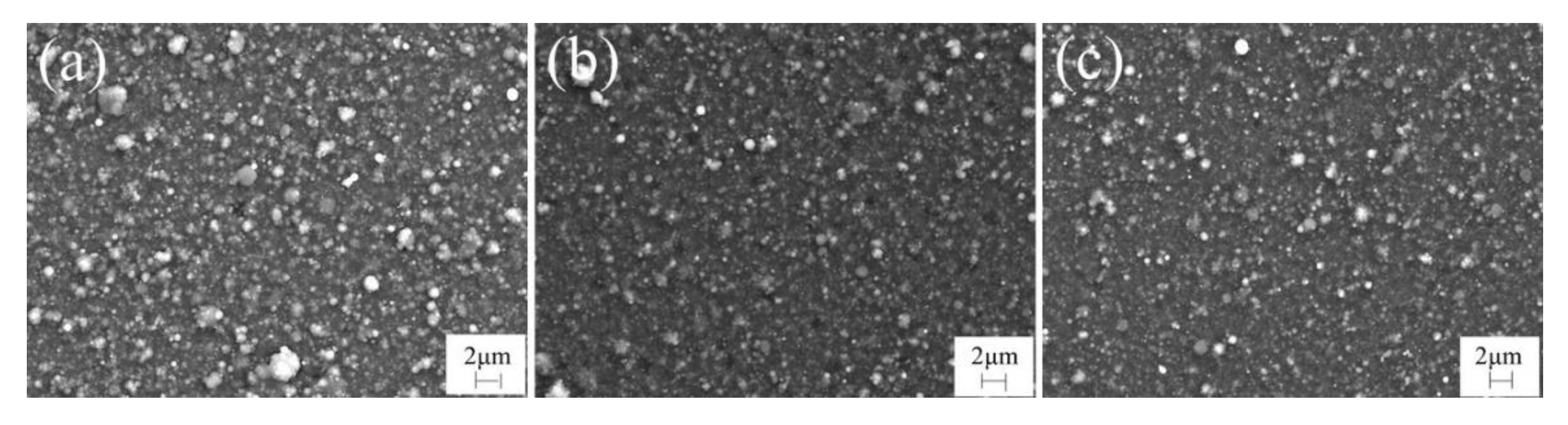
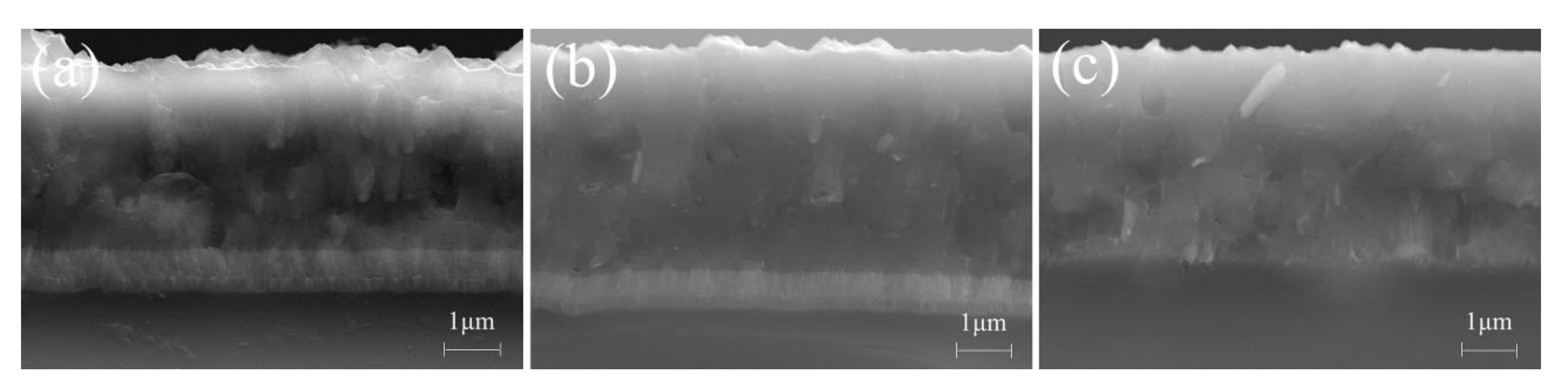
3.1. Deposition Rate and Microstructure

The deposition rates of the AlCrSiN coating, AlCrSiON coating, and AlCrSiN/AlCrSiON duplex coating are shown in Figure 2. It can be seen that the difference among them is not obvious. The deposition rate of AlCrSiN coating is about 22.3 ± 0.6 nm/min, and that of AlCrSiON coating is the about 24.5 ± 0.7 nm/min, while that of AlCrSiN/AlCrSiON duplex coating is somewhere in between. The above tendency was attributed to the addition of oxygen, the rapid oxidation reaction resulted in the formation of oxide substance with bigger volume, so the deposition rate was increased slightly. Whereas the time of oxygen input was reduced during the deposition of the AlCrSiN/AlCrSiON duplex coating, which led to a slight decrease in the deposition rate.
Figure 3 presents the typical surface morphologies of the AlCrSiN coating, AlCrSiON coating, and AlCrSiN/AlCrSiON duplex coating, respectively. It can be seen that there are some defects such as macro particles, pinholes and solid droplets on the surface of the three coatings—which were due to the ion cluster collision during the coating process to form large particles or the metal droplets evaporated from the target surface—which were directly deposited on the substrate, and rapid cooling and shrinkage formed defects occurred with the decrease in temperature [22,23]. Compared with the AlCrSiN coating (Figure 3a), both the amount and size of macro particles on the AlCrSiON coating (Figure 3b) and AlCrSiN/AlCrSiON duplex coating (Figure 3c) were significantly reduced. There are two possible reasons for this. One is that the droplets emitted from the target surface were usually positively charged from metal ions. Oxygen reacts with metal ions more easily than nitrogen to generate neutral particles due to the higher activity of former. Moreover, if the droplet is bigger, the oxidation reaction is more sufficient. In the negative bias electric field near the substrate, these neutral particles could be accelerated, which induced smaller and fewer of macroparticles formed on the resulted coating surface [24]. The other reason is attributed to the well-known target-poisoning effect as oxygen is introduced. The gradual accumulation of weakly electrically conductive oxide films on the target surface further hindered the evaporation of many larger droplets, which formed the smoother coating surface [25]. However, more pinholes can be observed in Figure 3b,c than those in Figure 3a, which is attributed to the change in the tissue volume caused by the formation of oxides.
The fractured cross-sectional images of above three coatings are shown in Figure 4. All the coatings presented a featureless glassy microstructure, and no obvious boundary could be observed between the AlCrSiN layer and AlCrSiON layer in the AlCrSiN/AlCrSiON duplex coating. The AlCrSiON coating and AlCrSiN/AlCrSiON duplex coating are denser than the AlCrSiN coating. This indicates that the introduction of oxygen enhanced the forming ability of the nanocomposite structure. Namely, the amorphous layers inhibited the nanocrystal growth by surrounding them, which led to a dense microstructure. The three coatings were also well bonded to the substrate, which is due to the gradient change in the bias voltage during coating deposition. The kinetic energy of the evaporated particles was adjusted by changing the substrate bias. The variation in the bombardment effect could change the surface energy of the coating and make an internal stress gradient distribution along the direction of the coating growth, which avoided the stress concentration and resulted in denser coating tissues [26]. A good adhesion was also obtained which was especially suitable for thick coating preparation. In Figure 4, all the CrN transition layers presented a columnar structure which grew perpendicularly to the substrate surface. Moreover, there was a thin Cr layer at the bottom of the CrN transition layer. This is because the decrease in substrate bias in the later stage of ion bombardment cleaning reduced the ion energy and caused a thin Cr layer deposit on the substrate surface.

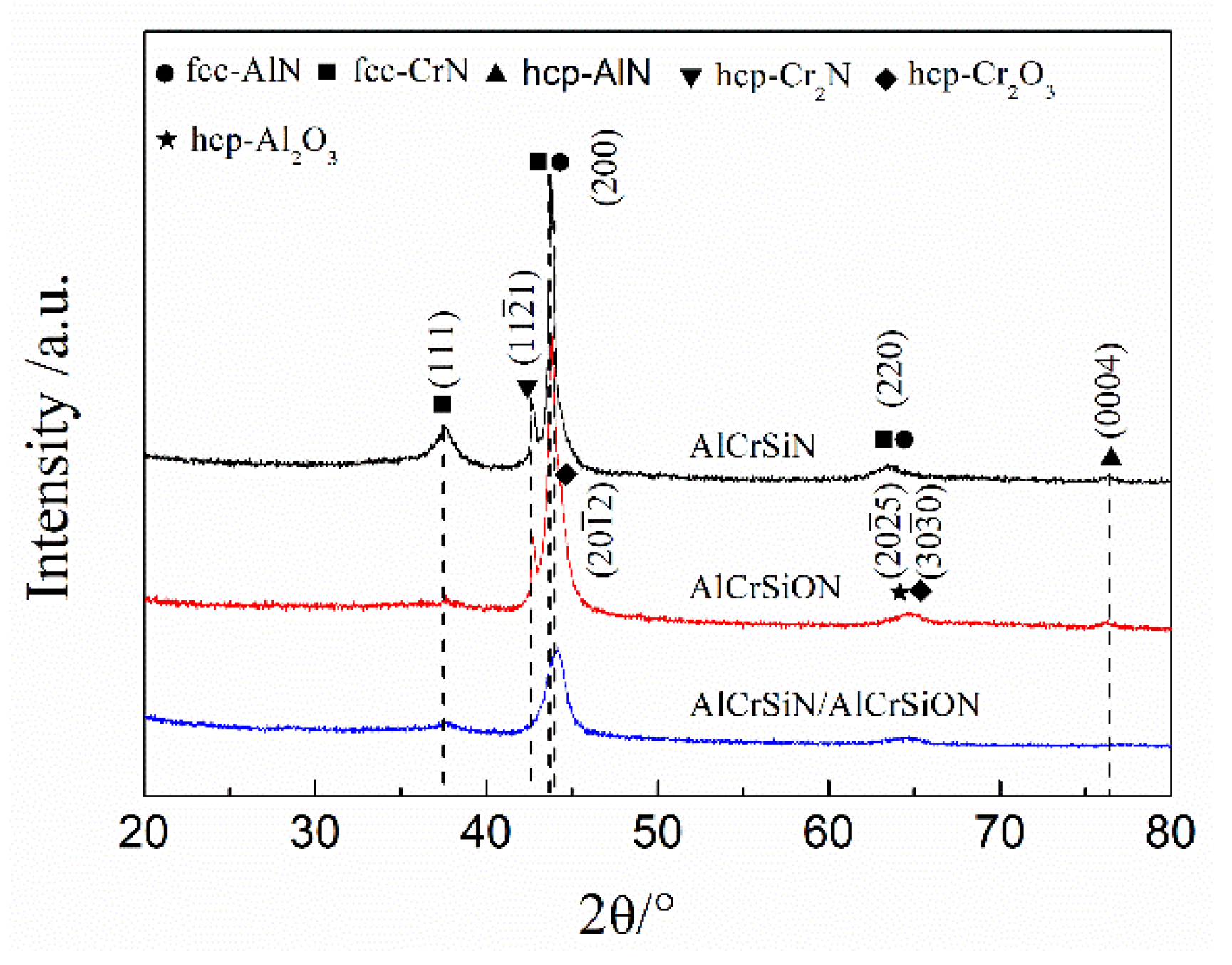
3.2. Composition and Phase Constituents

Because the AlCrSiN/AlCrSiON duplex coating consisted of an underlying AlCrSiN layer and an outermost AlCrSiON layer, here only the compositions of the AlCrSiN coating and AlCrSiON coating are analyzed and compared. Table 2 listed the contents of element Al, Cr, Si, O, and N in the AlCrSiN coating and AlCrSiON coating. It can be found that the atomic ratios of Al vs. Cr in both coatings were less than that of the target, but the atomic ratios of Al vs. Si in both coatings were more than that of the target. The above phenomena were attributed to the different evaporation efficiencies of Al, Cr, and Si elements in the target. Usually, their order of evaporation efficiency during coating deposition by arc ion plating is Cr > Al > Si [27]. After oxygen doping, the atomic ratios of Al, Cr, and Si in the AlCrSiON coating almost kept consistent with those of the AlCrSiN coating. However, their respective contents decreased slightly. In addition, the content of N in the AlCrSiON coating reduced significantly from 53.11% to 22.72% due to the higher chemical activity of oxygen than nitrogen [28].
Figure 5 showed the X-ray diffraction patterns of the AlCrSiN coating, AlCrSiON coating, and AlCrSiN/AlCrSiON duplex coating. It can be seen that the main phase of the three kinds of coatings was the fcc-(Al,Cr)N phase. The strongest diffraction peaks of the three coatings were partially overlapped diffraction peaks of the fcc-CrN and fcc-AlN grains when 2θ was 43.7° and 43.9°, and both grew along the (200) crystal plane. Moreover, the diffraction peak intensity of the AlCrSiN/AlCrSiON duple coating was significantly reduced, which may be due to the increase in internal stresses between the two coatings, leading to a distorted crystal structure, and structural defects could also cause the decrease in the diffraction peak intensity [14]. In addition, the fcc-CrN diffraction peaks on the (111) crystal plane at 2θ = 37.5° were detected for all the coatings, and the peak intensities of the AlCrSiON coating and AlCrSiN/AlCrSiON duplex coating were significantly lower than that of the AlCrSiN coating. This may be due to the partial substitution of nitrogen atoms by oxygen atoms, which led to the weakening of the CrN diffraction peak and also refined the grain growth. Moreover, the AlCrSiN coating and AlCrSiON coating exhibited the diffraction peaks of hcp-Cr2N on the ( 11 2 - 1 ) crystal plane and the diffraction peaks of hcp-AlN on the ( 00 0 - 4 ) crystal plane as 2θ was 42.6° and 76.4°, respectively. As the diffraction angle 2θ was 63.5° and 63.9°, the weak diffraction peaks of fcc-CrN and fcc-AlN grains on the (220) plane were detected in the AlCrSiN coating. The hcp-Al2O3 and hcp-Cr2O3 phases could also be identified in the AlCrSiON coating at 2θ = 64.6° and 65.1°, respectively. In all the XRD patterns, no diffraction peaks of silicon nitride or compounds containing silicon were detected, they maybe exist in the form of amorphous [8].

3.3. Mechanical Properties

Figure 6 showed the hardnesses of the AlCrSiN coating, AlCrSiON coating, and AlCrSiN/AlCrSiON duplex coating. It can be seen that the coating hardness decreased to some extent after adding oxygen. The AlCrSiN coating possessed the highest hardness of 4000 ± 190 HV. The hardness of the AlCrSiON coating decreased sharply to 3400 ± 140 HV after oxygen doping. However, the hardness of the AlCrSiN/AlCrSiON duplex coating maintained about 3800 ± 120 HV. Combined with the XRD spectrum (Figure 3), it was found that the high hardness of the AlCrSiN coating was mainly caused by the hard (Al,Cr)N phase, while the other two coatings impaired hardness due to the incorporation of oxygen [29]. The formation of brittle oxide made the cracks easy to initiate and expand, which led to the decrease in the coating hardness. In the AlCrSiN/AlCrSiON duplex coating, the heterogeneous interface played an important role in prohibiting the crack propagation, grain boundary sliding, and dislocation movement, so a certain strengthening effect was achieved. In addition, the harder underlying AlCrSiN layer also provided hard support. As a result, the hardness of the AlCrSiN/AlCrSiON duplex coating was between the AlCrSiN coating and AlCrSiON coating.
The scratch profile views of the AlCrSiN coating, AlCrSiON coating, and AlCrSiN/AlCrSiON coating shown in Figure 7a–c, and Figure 7d,e are partially enlarged views of the failure position of the three coatings. The scratch test is generally divided into three stages. One is the stage of micro cracks just entering the running, although the coating has slight cracks, and is not yet invalid. In the second stage, the coating begins to peel off locally, and the functionality of the layer is affected and the coating begins to fail. The load at this time is also defined as the critical load (Lc) indicating the adhesion between the coating and substrate. In the third stage, the coating is completely peeled off and the substrate is exposed, so the coating loses its function [30]. In this work, all three coatings did not exhibit the third stage when undergoing the maximum normal load of 150 N, which suggests an excellent adhesion between the coating and substrate. Figure 8 showed the critical loads of the three coatings. The AlCrSiN coating possessed the highest adhesive strength, and its critical load was about 80.9 ± 1.5 N; the AlCrSiON coating presented the lowest critical load of 50.6 ± 2.2 N; the critical load of AlCrSiN/AlCrSiON duplex coating was 70.7 ± 1.8 N. From Figure 7, it can be seen that the AlCrSiN coating and AlCrSiN/AlCrSiON duplex coating were accompanied by relatively large local spalling on both sides of the scratch scars, and much debris with a fish scale shape could be found. This is because a large number of brittle cracks occurred when the rockwell C diamond stylus moved across the hard coating surface. There was less local peeling on both sides of the scratch scar of the AlCrSiON coating, although its critical load was the lowest. The low hardness of the AlCrSiON coating was an important reason for the above phenomenon.

3.4. Tribological Behaviors
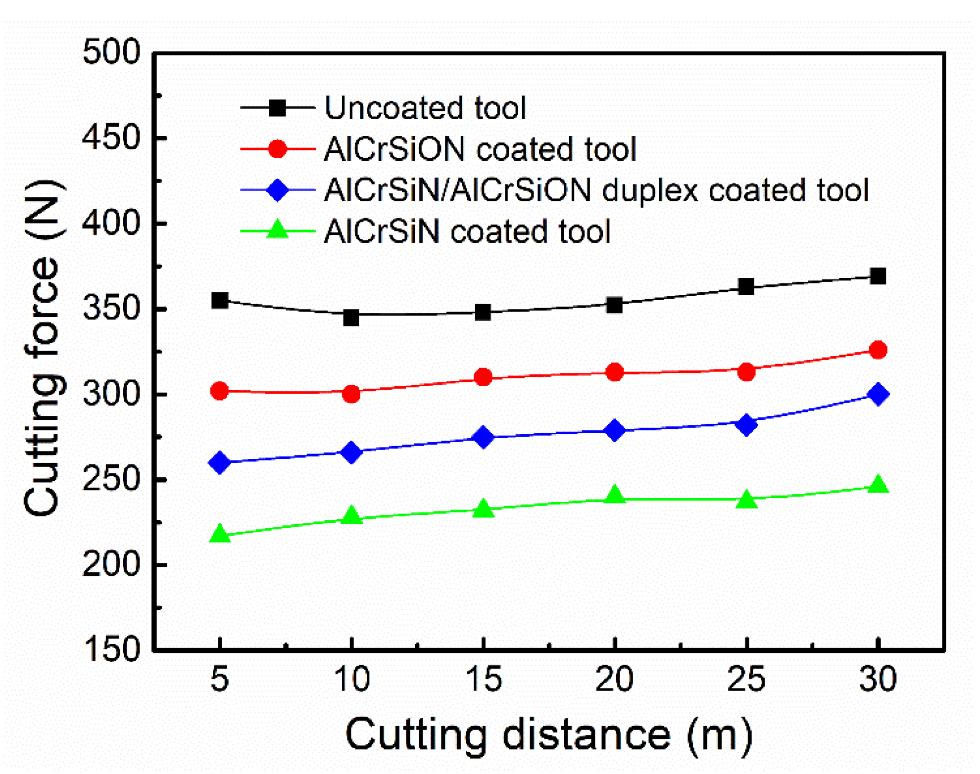
Figure 9 showed the average friction coefficients of the three coatings. It can be seen that the AlCrSiN coating had the lowest friction coefficient of 0.67 ± 0.02; whereas the friction coefficients of the other two oxygen-containing coatings were increased to some extent. This is because the alumina and/or chromium oxide in the oxygen-containing coating had a good affinity with the alumina ball, which led to the increase in the friction coefficient. Furthermore, the contact area between the coating and the alumina ball was also increased under the same normal load due to the low hardness, it could also increase the friction coefficient. The trend of the friction coefficient of the three coatings was consistent with that of their hardness, which also indirectly indicated that hardness is a vital factor in affecting the friction coefficient of the coating.
After tribological tests, the typical morphologies of the wear scars of the three coatings were shown in Figure 10. It can be seen that the wear scar of the AlCrSiON coating was wider and deeper than the other two coatings. There were some wear debris left on the surface of the wear scar. This was also due to the loose structure of the AlCrSiON coating, relatively low adhesion and hardness, and a high coefficient of friction resulting in a decrease in the wear resistance of the coating. The wear scar of the AlCrSiN coating was the shallowest and narrowest among them, which presented the best wear resistance. The micro furrows could be found on the surface of all wear scars, and the typical abrasive wear occurred. During the friction process, the hard particles and fragments from the coating and/or friction pair were gradually stripped off under the combined action of normal stress and shear stress. Then these debris were transferred to the friction interface and driven by the alumina ball with a high sliding speed, which thus participated in friction as the third body. The asperities with sharp edges repeatedly scratched the coating in the contact zone, which caused the micro furrow wear [31]. In view of the above, the main wear failure mechanism of the three coatings was plastic deformation, work hardening in the contact zone, the peeling off of the hard fragments, and micro ploughing.
To further compare the wear resistance of the three coatings, their wear rates were measured and are shown in Figure 11. The maximum depth measurement of the wear scars verified that all the coatings were not worn through after tribological tests. It can be seen from Figure 11 that the wear rate of the AlCrSiN coating was the lowest, that the AlCrSiN/AlCrSiON duplex coating was second, and the AlCrSiON coating was the highest. This trend is consistent with the results of the wear morphologies in Figure 10. According to the above analysis of coating compositions, microstructures, and mechanical properties, it can be found that a dense microstructure, high hardness, good adhesion, and low friction coefficient were the principle reasons for AlCrSiN coating presenting the best wear resistance. On the contrary, the AlCrSiON coating’s wear resistance was the worst, and that of AlCrSiN/AlCrSiON duplex coating was in between. In this work, although the preoxidation method and duplex coating design did not improve the resulted coating performance, it pointed out the direction for developing multilayer coatings, namely that the thickness of the oxygen-containing layer should be as small as possible and the multilayer interfaces should be used to improve toughness.

3.5. Cutting tests

In order to evaluate the cutting performance of the above three coatings, the flank wear widths of the solid cemented carbide end mills coated by three different coatings were compared after 90 min of dry milling C1045 medium-carbon steel. Figure 12a–c shows the typical flank wear profiles for the AlCrSiN coated end mill, AlCrSiON coated end mill, and AlCrSiN/AlCrSiON duplex coated end mill, respectively. It can be seen that flank wear occurred for all the coated solid cemented carbide end mills, and the tool substrate near the cutting-edge was exposed. Moreover, the evident coating spalling and failure on the flank and edge can be observed in Figure 12b,c. Whereas the AlCrSiN coating was only slightly worn through near the cutting-edge (Figure 12a), and its flank wear width was the smallest at around 135 μm. The AlCrSiN coated solid cemented carbide end mill can still be used after this test. The other two oxygen containing coated tools were seriously worn, and their flank wear widths were relatively large, at 294 and 204 μm, respectively. The AlCrSiON coated solid cemented carbide end mill presented the worst cutting performance that was attributed to the addition of oxygen impairing the coating toughness. As a result, the resulting coat was prone to cracking and peeling off under the action of complex stresses. This made it quickly lose protective function [32]. The AlCrSiN coating possessed a high hardness, good adhesion and tribological properties, which were the direct reasons for its excellent cutting performance.
Figure 13 showed the variation in the cutting force at a cutting distance from 5 to 30 m for the uncoated end mill, AlCrSiN coated end mill, AlCrSiON coated end mill, and AlCrSiN/AlCrSiON duplex coated end mill. It can be seen that the cutting force of the coated end mills was less than that of the uncoated end mill, which implies that the three coatings could improve the cutting performance of end mills to different extents. There were sparks in the cutting process for the uncoated end mill. The small cutting force can improve the machining accuracy and prolong tool life. Among the three coated tools, the cutting force of the AlCrSiN coated end mill was the minimum, that of the AlCrSiON coated end mill was the maximum, and that of the AlCrSiN/AlCrSiON duplex coated end mill was the medium. This trend is consistent with the change trend of the mechanical and tribological properties of the three coatings. Usually, the cutting force is directly related to the friction coefficient of the tool surface. In this work, the AlCrSiN coating possessed the lowest friction coefficient which led to its minimum cutting force under dry milling conditions. For the oxygen-containing coated tools, the spalling of the brittle oxide fragments from the coating and transfer to the interface between the cutting layer and rake face, as well as the high friction coefficient, are the reasons for the larger cutting force. In addition, the cutting force of both coated and uncoated tools was relatively stable and increased slightly with the increase in the cutting distance. On the one hand, the deformation of the cutting zone became larger with the increase in the cutting temperature, which resulted in an increasing cutting force [33]. On the other hand, the gradual wear of cutting tools is also one of the reasons for the increase in the cutting force.

4. Conclusions

In this work, the microstructure, composition, mechanical and tribological properties of the AlCrSiN coating, AlCrSiON coating, and AlCrSiN/AlCrSiON duplex coating were studied. The cutting experiments were carried out to verify the service performance of the above coatings. Some important conclusions were drawn:
(1)
All the coatings possessed the dense structure, and the face-centered cubic (Al,Cr)N crystallites preferentially grew along the (200) crystal plane. However, a hexagonal oxide phase appeared in the AlCrSiON coating.
(2)
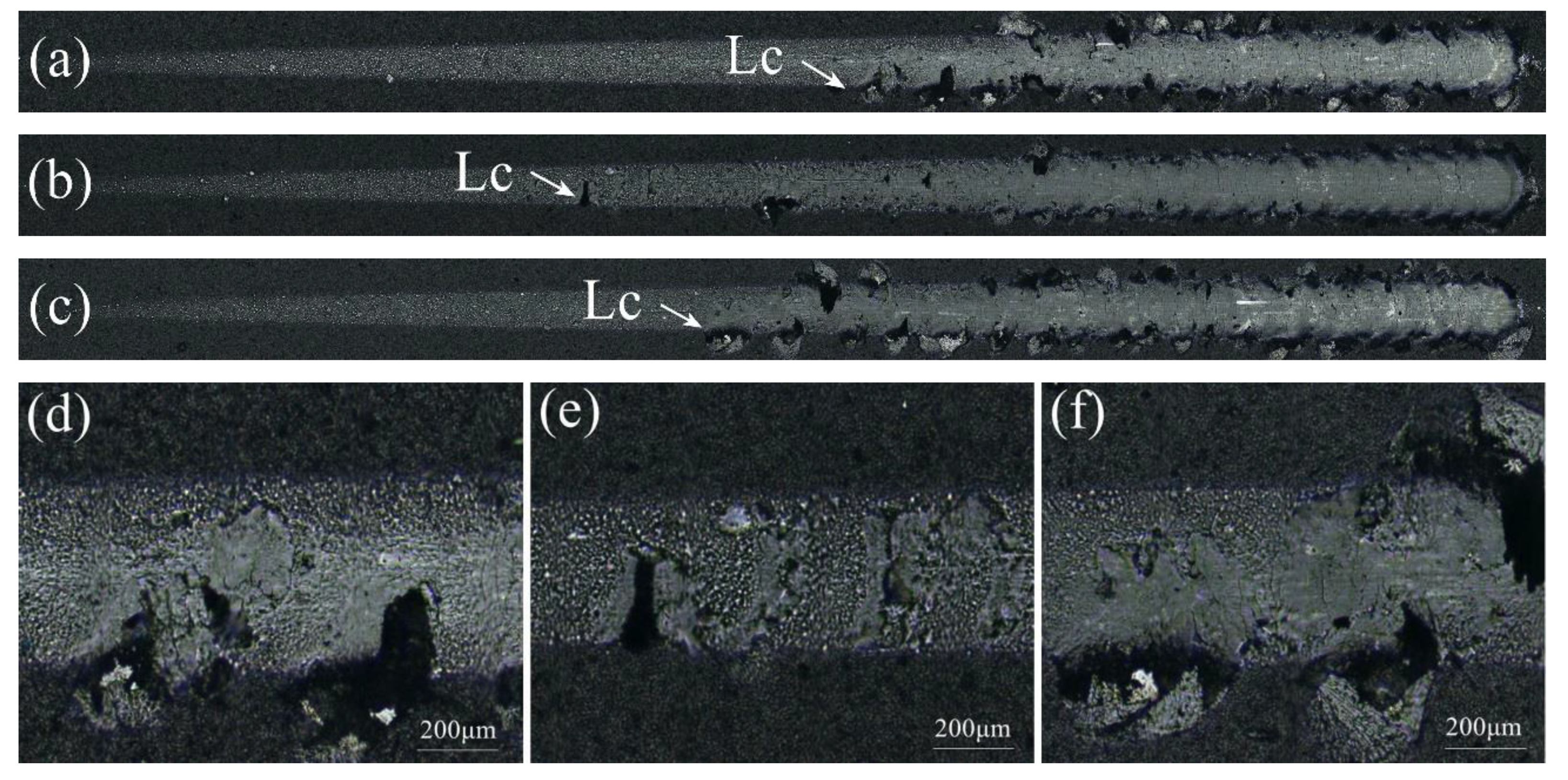
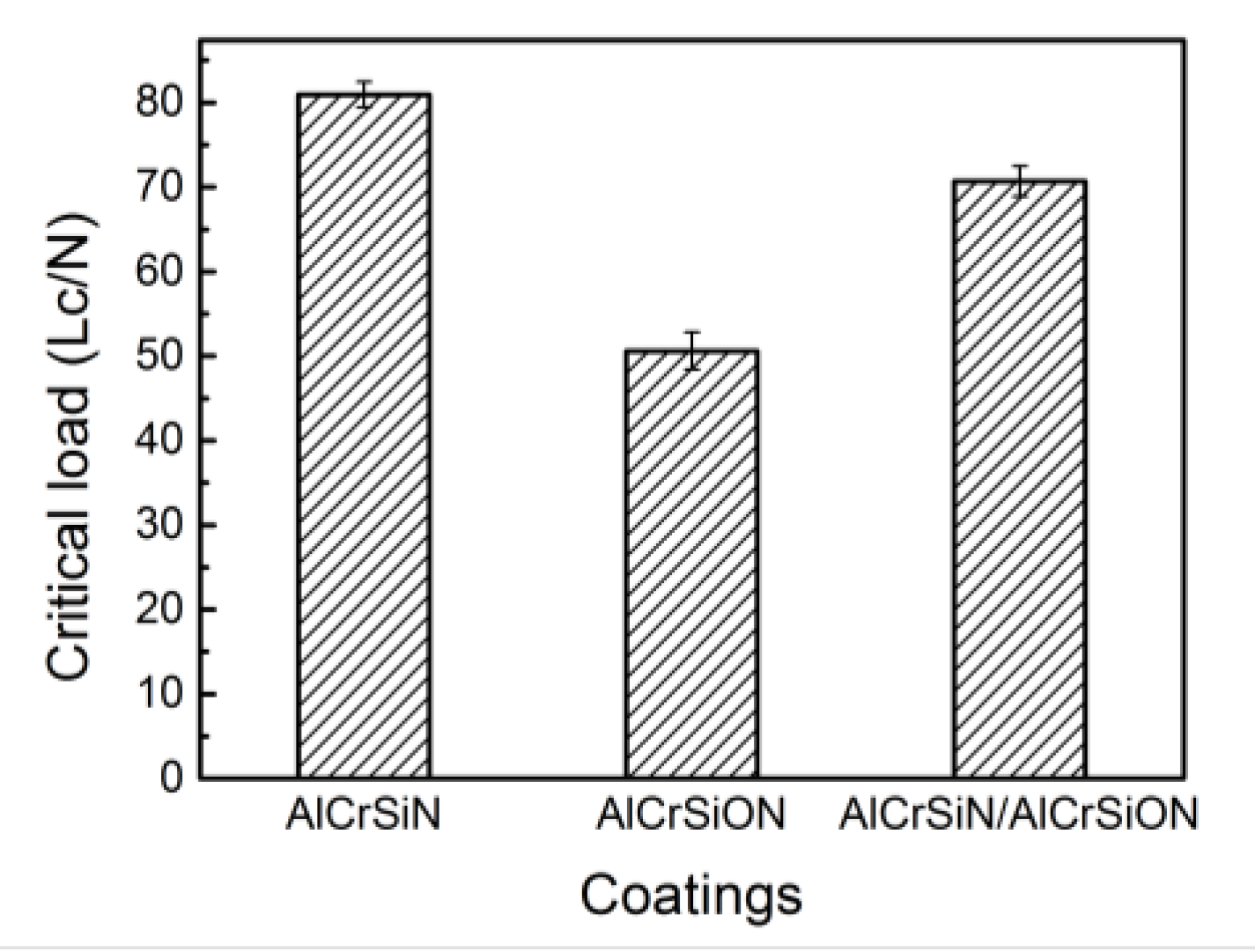
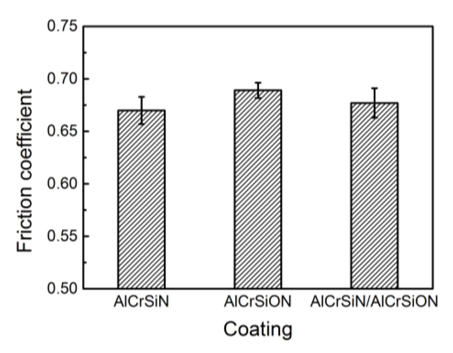
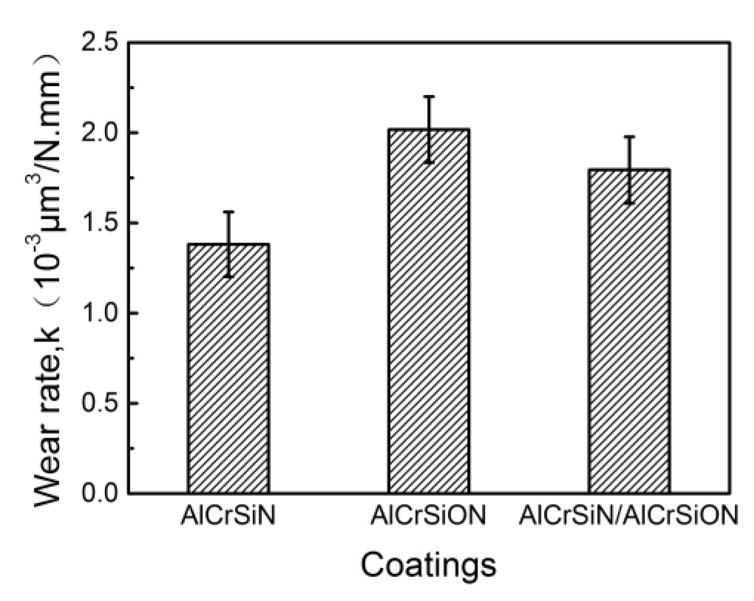
The AlCrSiN coatings possessed the best mechanical properties, and the coating hardness and critical load reached 4000 HV and 81 N, respectively. Moreover, this coating showed the lowest friction coefficient and the best wear resistance.
(3)
By a comparison of cutting tests, the Al-Cr-Si-N coated tool presented the minimum cutting force. After 90 min of dry milling, the width of flank wear of the AlCrSiN coated tool reached 135 μm, which was much lower than that of the AlCrSiON coated tool and AlCrSiN/AlCrSiON duplex coated tool.

Author Contributions

Conceptualization, Y.L. and T.-G.W.; methodology, W.L.; validation, Q.Z., X.H. and T.-G.W.; formal analysis, X.H.; investigation, W.L. and B.Y.; resources, B.Y.; data curation, Q.Z.; writing—original draft preparation, W.L.; writing—review and editing, Y.L.; supervision, T.-G.W.; project administration, T.-G.W.; funding acquisition, T.-G.W. All authors have read and agreed to the published version of the manuscript.

Funding

This research was funded by National Natural Science Foundation of China (51301181 and 51875555), Tianjin Science and Technology Major Project (18ZXJMTG00050), and Tianjin Natural Science Foundation (19JCYBJC17100).

Conflicts of Interest

The authors declare no conflict of interest.

References

  1. Bag, R.; Panda, A.; Sahoo, A.K.; Kumar, R. Cutting tools characteristics and coating depositions for hard part turning of AISI 4340 martensitic steel: A review study. Mater. Today Proc. 2020, 26, 2073–2078. [Google Scholar] [CrossRef]
  2. Vereschaka, A.; Tabakov, V.; Grigoriev, S.; Sitnikov, N.; Milovich, F.; Andreev, N.; Sotova, C.; Kutina, N. Investigation of the influence of the thickness of nanolayers in wear-resistant layers of Ti-TiN-(Ti,Cr,Al)N coating on destruction in the cutting and wear of carbide cutting tools. Surf. Coat. Technol. 2020, 385, 125402. [Google Scholar] [CrossRef]
  3. Zhao, J.; Liu, Z. Influences of coating thickness on cutting temperature for dry hard turning Inconel 718 with PVD TiAlN coated carbide tools in initial tool wear stage. J. Manuf. Process. 2020, 56, 1155–1165. [Google Scholar] [CrossRef]
  4. He, Q.; Paiva, J.M.; Kohlscheen, J.; Beake, B.; Veldhuis, S. An integrative approach to coating/carbide substrate design of CVD and PVD coated cutting tools during the machining of austenitic stainless steel. Ceram. Int. 2020, 46, 5149–5158. [Google Scholar] [CrossRef]
  5. Iram, S.; Cai, F.; Wang, J.; Zhang, J.; Liang, J.; Ahmad, F.; Zhang, S. Effect of Addition of Mo or V on the Structure and Cutting Performance of AlCrN-Based Coatings. Coatings 2020, 10, 298. [Google Scholar] [CrossRef] [Green Version]
  6. Hao, G.; Liu, Z.; Liang, X.; Zhao, J. Influences of TiAlN coating on cutting temperature during orthogonal machining H13 hardened steel. Coatings 2019, 9, 355. [Google Scholar] [CrossRef] [Green Version]
  7. Liu, Z.R.; Xu, Y.X.; Peng, B.; Wei, W.; Chen, L.; Wang, Q. Structure and property optimization of Ni-containing AlCrSiN coatings by nano-multilayer construction. J. Alloy. Compd. 2019, 808, 151630. [Google Scholar] [CrossRef]
  8. Cai, F.; Gao, Y.; Zhang, S.; Zhang, L.; Wang, Q. Gradient architecture of Si containing layer and improved cutting performance of AlCrSiN coated tools. Wear 2019, 193–202. [Google Scholar] [CrossRef]
  9. Bobzin, K.; Brögelmann, T.; Kruppe, N.; Carlet, M. Wear behavior and thermal stability of HPPMS (Al,Ti,Cr,Si)ON, (Al,Ti,Cr,Si)N and (Ti,Al,Cr,Si)N coatings for cutting tools. Surf. Coat. Technol. 2020, 385, 125370. [Google Scholar] [CrossRef]
  10. Bobzin, K.; Brögelmann, T.; Kruppe, N.; Carlet, M. Nanocomposite (Ti,Al,Cr,Si)N HPPMS coatings for high performance cutting tools. Surf. Coat. Technol. 2019, 378, 124857. [Google Scholar] [CrossRef]
  11. Liu, Z.R.; Peng, B.; Xu, Y.X.; Zhang, Q.; Wang, Q.; Chen, L. Influence of Ni-addition on mechanical, tribological properties and oxidation resistance of AlCrSiN coatings. Ceram. Int. 2019, 45, 3735–3742. [Google Scholar] [CrossRef]
  12. Tillmann, W.; Fehr, A.; Stangier, D. Microstructural and tribological properties of sputtered AlCrSiWN films deposited with segmented powder metallurgic target materials. Thin Solid Films 2019, 687, 137465. [Google Scholar] [CrossRef]
  13. Lukaszkowicz, K.; Kubacki, J.; Balin, K.; Sondor, J.; Pancielejko, M. Characteristics of CrAlSiN+MoS2 coating deposited by cathodic arc and magnetron sputtering process. Vacuum 2019, 163, 360–367. [Google Scholar] [CrossRef]
  14. Ahmad, F.; Zhang, L.; Zheng, J.; Sidra, I.; Cai, F.; Zhang, S. Structural evolution and high-temperature tribological properties of AlCrON coatings deposited by multi-arc ion plating. Ceram. Int. 2020. [Google Scholar] [CrossRef]
  15. Geng, D.; Li, H.; Zhang, Q.; Zhang, X.; Wang, C.; Wu, Z.; Wang, Q. Effect of incorporating oxygen on microstructure and mechanical properties of AlCrSiON coatings deposited by arc ion plating. Surf. Coat. Technol. 2017, 310, 223–230. [Google Scholar] [CrossRef]
  16. Chen, W.; Fang, B.; Zhang, D.; Meng, X.; Zhang, S. Thermal stability and mechanical properties of HVOF/PVD duplex ceramic coatings produced by HVOF and cathodic vacuum arc. Ceram. Int. 2017, 43, 7415–7423. [Google Scholar] [CrossRef]
  17. Li, W.; Tang, P.; Shang, L.; He, D.; Wang, L.; Zhang, G.; Jin, K. Tribological behaviors of CrN/Cr3C2-NiCr duplex coating at elevated temperatures. Surf. Coat. Technol. 2019, 378, 124926. [Google Scholar] [CrossRef]
  18. Hou, Z.; Zhang, J.; Zhang, P.; Wu, K.; Li, J.; Wang, Y.; Liu, G.; Zhang, G.; Sun, J. Modulation-dependent deformation behavior and strengthening response in nanostructured Ti/Zr multilayers. Appl. Surf. Sci. 2020, 502, 144118. [Google Scholar] [CrossRef]
  19. Li, B.S.; Wang, T.G.; Ding, J.; Cai, Y.; Shi, J.; Zhang, X. Influence of N2/Ar flow ratio on microstructure and properties of the AlCrSiN coatings deposited by high-power impulse magnetron sputtering. Coatings 2018, 8, 3. [Google Scholar] [CrossRef] [Green Version]
  20. Zhang, J.J.; Wang, T.G.; Yan, B.; Liu, Y.; Jiang, S.; Dong, Y. Influence of DC bias voltage on structure and performance of the Al-Cr-Si-N coatings prepared by arc ion plating technique. Rare Metal. Mat. Eng. 2018, 47, 2232–2239. [Google Scholar]
  21. Toubhans, B.; Fromentin, G.; Viprey, F.; Karaouni, H.; Dorlin, T. Machinability of inconel 718 during turning: Cutting force model considering tool wear, influence on surface integrity. J. Mater. Process. Technol. 2020, 285, 116809. [Google Scholar] [CrossRef]
  22. Li, G.; Zhang, L.; Cai, F.; Yang, Y.; Wang, Q.; Zhang, S. Characterization and corrosion behaviors of TiN/TiAlN multilayer coatings by ion source enhanced hybrid arc ion plating. Surf. Coat. Technol. 2019, 366, 355–365. [Google Scholar] [CrossRef]
  23. Wang, L.; Wang, M.; Chen, H. Corrosion mechanism investigation of TiAlN/CrN superlattice coating by multi-arc ion plating in 3.5 wt% NaCl solution. Surf. Coat. Technol. 2020, 391, 125660. [Google Scholar] [CrossRef]
  24. Zhang, Y.; Dai, J.; Bai, G.; Zhang, H. Microstructure and thermal conductivity of AlN coating on Cu substrate deposited by arc ion plating. Mater. Chem. Phys. 2020, 241, 122374. [Google Scholar] [CrossRef]
  25. Arif, M.; Eisenmenger-Sittner, C. In situ assessment of target poisoning evolution in magnetron sputtering. Surf. Coat. Technol. 2017, 324, 345–352. [Google Scholar] [CrossRef]
  26. Zhao, B.; Zhao, X.; Lin, L.; Zou, L. Effect of bias voltage on mechanical properties, milling performance and thermal crack propagation of cathodic arc ion-plated TiAlN coatings. Thin Solid Films 2020, 708, 138116. [Google Scholar] [CrossRef]
  27. Liu, Y.; Sun, J.; Pei, Z.; Li, W.; Liu, J.; Gong, J.; Sun, C. Oxidation and hot corrosion behavior of NiCrAlYSi+NiAl/cBN abrasive coating. Corros. Sci. 2020, 167, 108486. [Google Scholar] [CrossRef]
  28. Liang, J.; Chen, S.; Zou, C.; Tian, C.; Wang, T.; Liao, S. Influence of oxygen contents on the microstructure, high temperature oxidation and corrosion resistance properties of Cr–Si–O–N coatings. Coatings 2018, 8, 19. [Google Scholar] [CrossRef] [Green Version]
  29. Karimi, A.; Morstein, M.; Cselle, T. Influence of oxygen content on structure and properties of multi-element AlCrSiON oxynitride thin films. Surf. Coat. Technol. 2010, 204, 2716–2722. [Google Scholar] [CrossRef]
  30. Tillmann, W.; Grisales, D.; Stangier, D.; Ben Jebara, I.; Kang, H. Influence of the etching processes on the adhesion of TiAlN coatings deposited by DCMS, HiPIMS and hybrid techniques on heat treated AISI H11. Surf. Coat. Technol. 2019, 378, 125075. [Google Scholar] [CrossRef]
  31. Wang, T.-G.; Zhao, S.-S.; Hua, W.-G.; Gong, J.; Sun, C. Design of a separation device used in detonation gun spraying system and its effects on the performance of WC–Co coatings. Surf. Coat. Technol. 2009, 203, 1637–1644. [Google Scholar] [CrossRef]
  32. Barthelmä, F.; Frank, H.; Mahr, P.; Reich, S. Oxygen-improved hard coatings for high performance cutting processes. Procedia CIRP 2012, 1, 208–213. [Google Scholar] [CrossRef] [Green Version]
  33. Pang, X.; Zhang, Y.; Wang, C.; Chen, Z.; Tang, N.; Chen, B. Effect of cutting parameters on cutting force and surface quality in cutting of articular cartilage. Procedia CIRP 2020, 89, 116–121. [Google Scholar] [CrossRef]
Figure 1. Photo of the dynamometer and the workpiece clamped in the workplace of machining enter.
Coatings 10 00841 g001
Figure 2. Deposition rates of the AlCrSiN coating, AlCrSiON coating, and AlCrSiN/AlCrSiON duplex coating.
Coatings 10 00841 g002
Figure 3. Surface morphologies of the three coatings: (a) AlCrSiN coating, (b) AlCrSiON coating, (c) AlCrSiN/AlCrSiON duplex coating.
Coatings 10 00841 g003
Figure 4. Fractured cross-sectional SEM images of the three coatings: (a) AlCrSiN coating, (b) AlCrSiON coating, (c) AlCrSiN/AlCrSiON duplex coating.
Coatings 10 00841 g004
Figure 5. X-ray diffraction patterns of the AlCrSiN coating, AlCrSiON coating, and AlCrSiN/AlCrSiON duplex coating.
Coatings 10 00841 g005
Figure 6. Hardnesses of the AlCrSiN coating, AlCrSiON coating, and AlCrSiN/AlCrSiON duplex coating.
Coatings 10 00841 g006
Figure 7. Images of scratch scar and partial enlargement of the three coatings after scratch tests, (a,d) AlCrSiN coating, (b,e) AlCrSiON coating, (c,f) AlCrSiN/AlCrSiON duplex coating.
Coatings 10 00841 g007
Figure 8. Critical loads of the AlCrSiN coating, AlCrSiON coating, and AlCrSiN/AlCrSiON duplex coating.
Coatings 10 00841 g008
Figure 9. Average friction coefficients of the AlCrSiN coating, AlCrSiON coating, and AlCrSiN/AlCrSiON duplex coating.
Coatings 10 00841 g009
Figure 10. Morphologies of wear scar of the (a) AlCrSiN coating, (b) AlCrSiON coating, and (c) AlCrSiN/AlCrSiON duplex coating.
Coatings 10 00841 g010
Figure 11. Wear rates of the AlCrSiN coating, AlCrSiON coating, and AlCrSiN/AlCrSiON duplex coating.
Coatings 10 00841 g011
Figure 12. Wear profiles of flank after cutting tests: (a) AlCrSiN coated end mill, (b) AlCrSiON coated end mill, and (c) AlCrSiN/AlCrSiON duplex coated end mill.
Coatings 10 00841 g012
Figure 13. Variation of cutting force at the cutting distance from 5 to 30 m for the uncoated tool, AlCrSiN coated tool, AlCrSiON coated tool, and AlCrSiN/AlCrSiON duplex coated tool.
Coatings 10 00841 g013
Table 1. Detailed deposition parameters for the AlCrSi(O)N coatings prepared by arc ion plating.
ParameterValues
Base pressure/Pa2.0 × 10−3
Working pressure/Pa2.9
Deposition temperature/°C450
Arc current of AlCrSi cathode/A100
Bias voltage/V80–200
N2/Ar/O2 gas flow ratio/Sccm600/50/20
Substrate rotation speed/(r·min−1)20
Distance between the target and substrate/mm220
Table 2. Chemical compositions of the AlCrSiN coating and AlCrSiON coating (at.%).
CoatingAl CrSiNOAl:CrAl:Si
AlCrSiN26.1616.694.0453.1101.576.48
AlCrSiON24.6214.423.7922.7234.461.716.50

