Experimental Study on Coal Fly Ash-Based Gas-Sealing Coating Used for Coal Mine Roadway Walls

Abstract
:1. Introduction
2. Materials and Methods
2.1. Experimental Materials
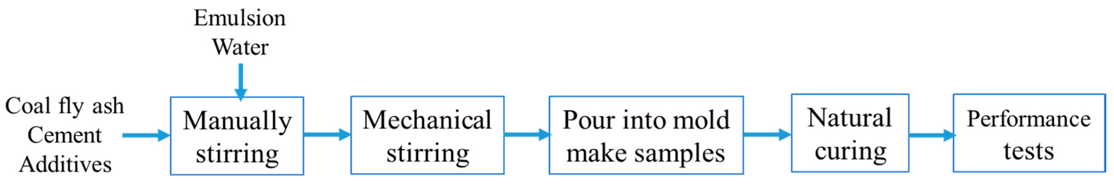
2.2. Experimental Methods
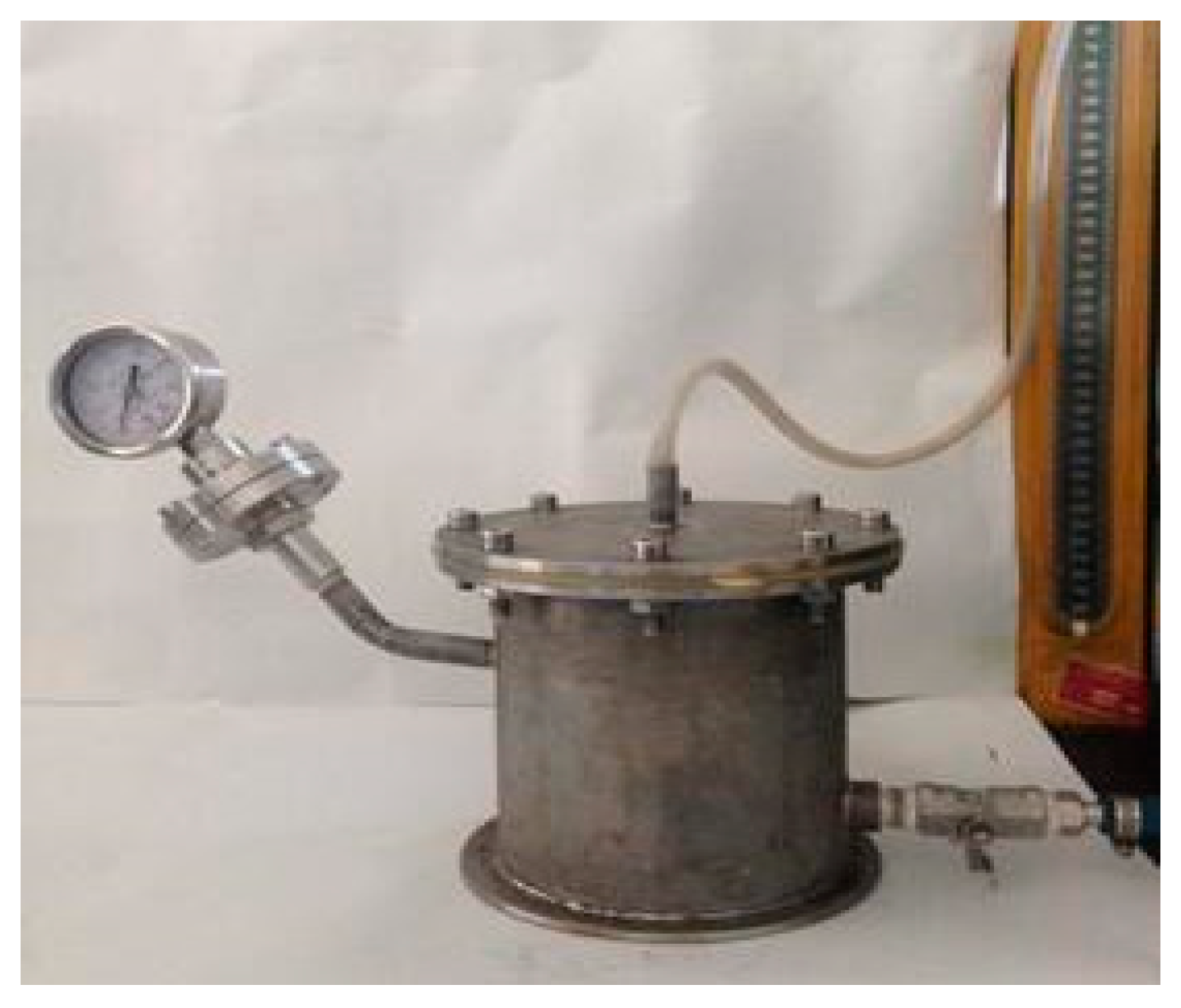
2.3. Coating Air Tightness Detection Method
3. Results and Discussion
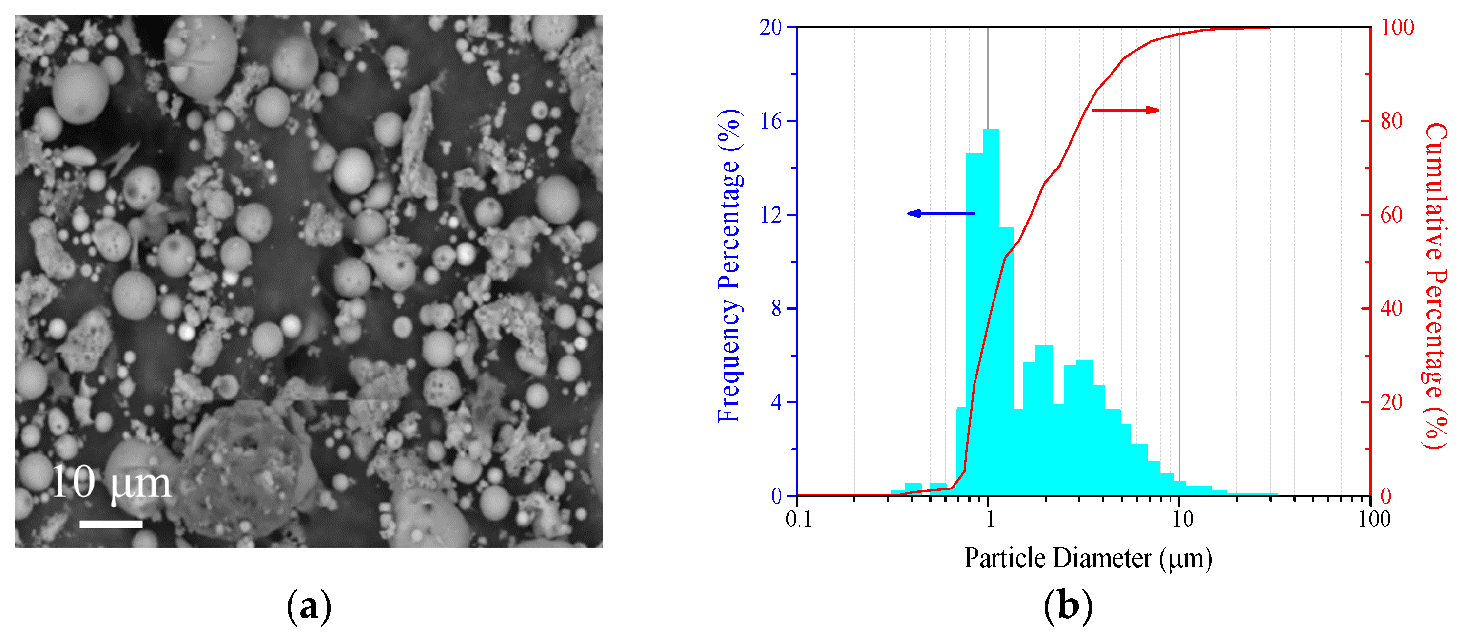
3.1. Analysis of Ultrafine CFA
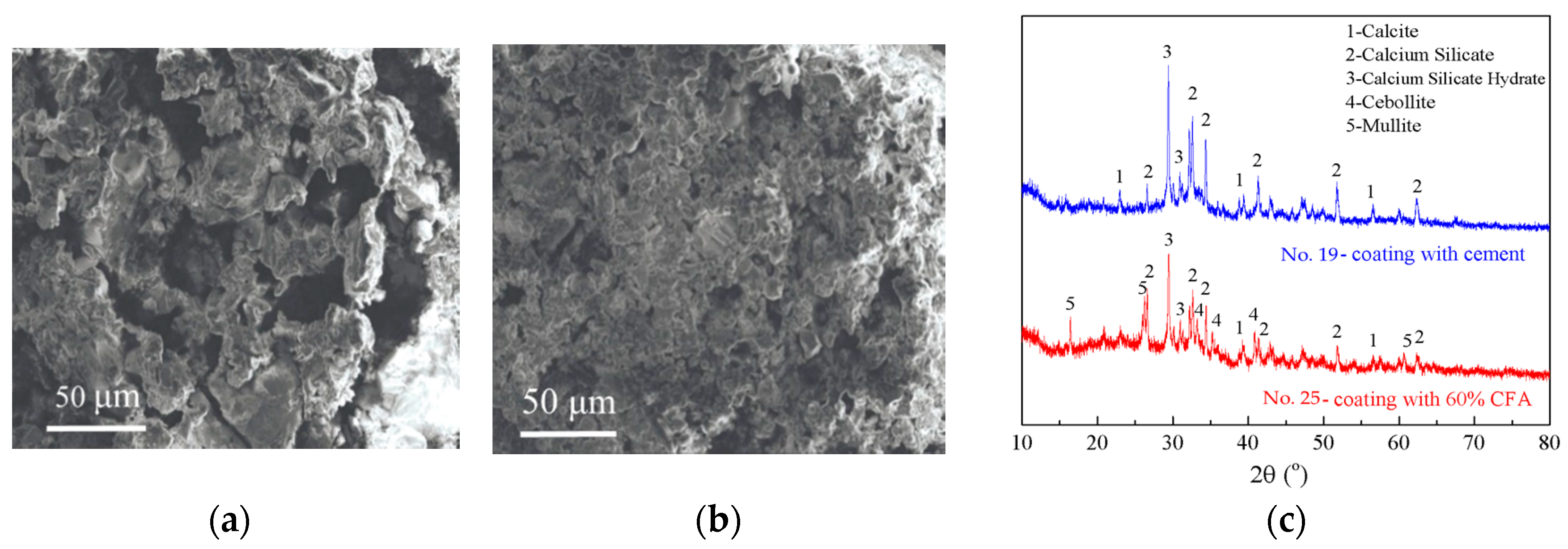
3.2. The Apparent Performance of Coatings
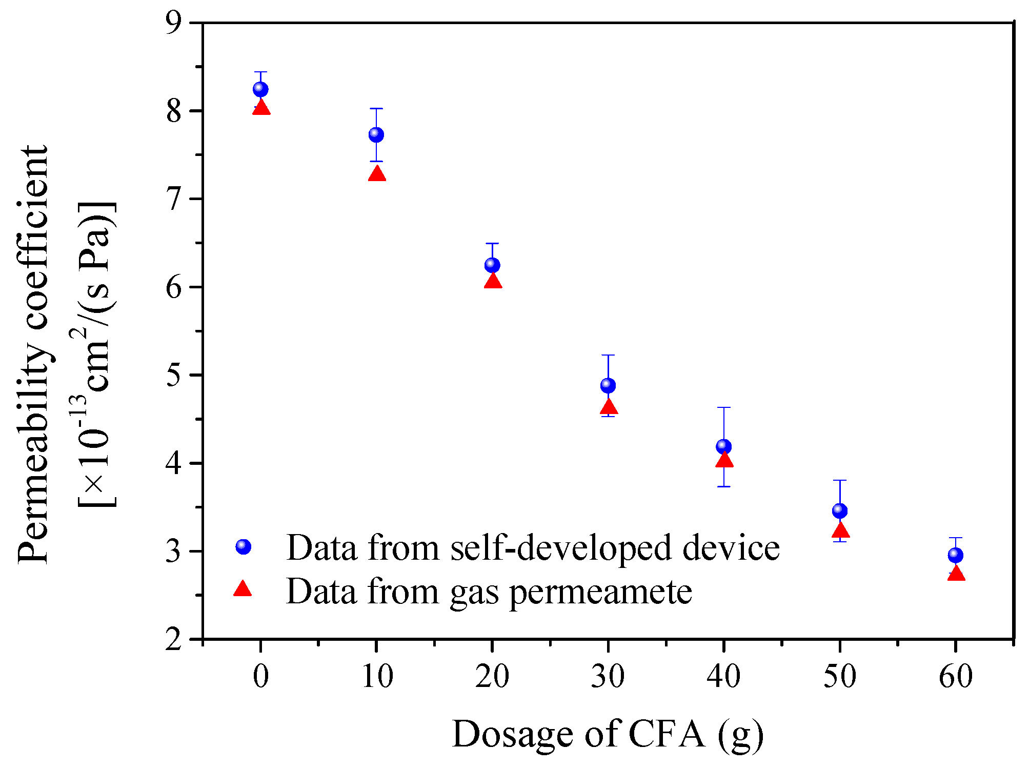
3.3. Air Tightness Detection of Coating Specimens with Different Additive Amounts of CFA
3.4. Impermeability Test of Coatings
3.5. Flame-Retardant and Static Electricity Test
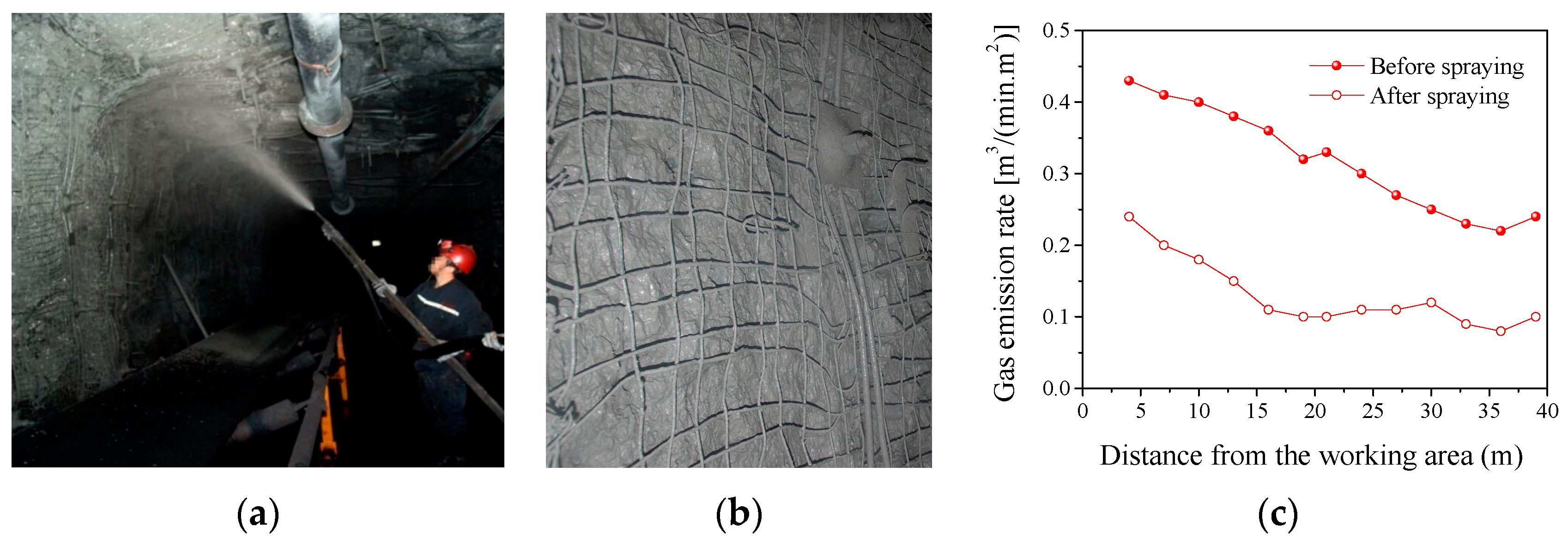
3.6. Application of CFA-Based Gas-Sealing Coating
4. Conclusions
Supplementary Materials
Author Contributions
Funding
Conflicts of Interest
References
- Meng, X.F.; Liu, Q.L.; Luo, X.X.; Zhou, X.X. Risk assessment of the unsafe behaviors of humans in fatal gas explosion accidents in China’s underground coal mines. J. Clean. Prod. 2019, 210, 970–976. [Google Scholar] [CrossRef]
- Pei, X.D.; Wang, K.; Jiang, S.G.; Wu, Z.Y.; Shao, H. Experimental study on ventilation supply–demand matching to dispense the stope gas disaster risk of coal mines. Geomat. Nat. Haz. Risk 2020, 11, 1299–1318. [Google Scholar] [CrossRef]
- Euler, D.S. Application of ventilation management programs for improved mine safety. Int. J. Min. Sci. Technol. 2017, 27, 647–650. [Google Scholar] [CrossRef]
- Ju, Y.W.; Sun, Y.; Sa, Z.Y.; Pan, J.N.; Wang, J.L.; Hou, Q.L.; Li, Q.G.; Yan, Z.F.; Liu, J. A new approach to estimate fugitive methane emissions from coal mining in China. Sci. Total Environ. 2016, 543, 514–523. [Google Scholar] [CrossRef] [PubMed]
- Ran, V.K.S. Spontaneous heating and fire in coal mines. Procedia Eng. 2013, 62, 78–90. [Google Scholar] [CrossRef] [Green Version]
- Karacan, C.Ö.; Ruiz, F.A.; CotèCoal, M. Mine methane: A review of capture and utilization practices with benefits to mining safety and to greenhouse gas reduction. Int. J. Coal Geol. 2011, 86, 121–156. [Google Scholar] [CrossRef]
- Wang, K.; Lou, Z.; Wei, G.Y.; Qin, B.B.; Wang, L. A novel anti-air-leakage method and an organic polymer material for improving methane drainage performance. Process. Saf. Environ. 2019, 129, 152–162. [Google Scholar] [CrossRef]
- Guo, J.; Cai, G.B.; Jin, Y.; Zheng, X.Z.; Liu, Y. An improved composite fly ash gel to extinguish underground coal fire in close distance coal seams: A case study. Adv. Mater. Sci. Eng. 2020, 5695471, 1–11. [Google Scholar] [CrossRef]
- Zhou, F.B.; Shi, B.B.; Liu, Y.K.; Song, X.L.; Cheng, J.W.; Hu, S.Y. Coating material of air sealing in coal mine: Clay composite slurry (CCS). Appl. Clay Sci. 2013, 80, 299–304. [Google Scholar] [CrossRef]
- Tian, L.; Liu, S.; Li, Y. Application of inorganic solidified foam to control the coexistence of unusual methane emission and spontaneous combustion of coal in the Luwa coal mine, China. Combust. Sci. Technol. 2020, 192, 638–656. [Google Scholar] [CrossRef]
- Song, H.P.; Liu, J.Q.; Xue, F.B.; Cheng, F.Q. The application of ultra-fine fly ash in the seal coating for the wall of underground coal mine. Adv. Powder. Technol. 2016, 27, 1645–1650. [Google Scholar] [CrossRef]
- Song, H.P.; Liu, J.Q.; Xue, F.B.; Cheng, F.Q. Inorganic powder of the coal mine tunnel waterproof material used in coal mine. Polymer 2016, 61, 844–849. [Google Scholar] [CrossRef]
- Zhai, C.; Hao, Z.Y.; Lin, B.Q. Research on a new composite sealing material of gas drainage borehole and its sealing performance. Procedia Eng. 2011, 26, 1406–1416. [Google Scholar] [CrossRef] [Green Version]
- Rubber, Vulcanized or Thermoplasitic Determination of Permeability to Gases; GB/T 7755-2003; General Administration of Quality Supervision: Inspection and Quarantine of the People’s Republic of China (AQSIQ): Beijing, China, 2003.
- Lang, Y.R.; Jang, H.P.; Wang, Y.Q.; Li, Z.; Zhang, L.Q. Structure and properties of OMMT/IIR nanocomposites. China Rubber Ind. 2005, 52, 261–265. [Google Scholar] [CrossRef]
- Fly Ash Used in Cement and Concrete; GB/T 1596-2005; General Administration of Quality Supervision: Inspection and Quarantine of the People’s Republic of China (AQSIQ); Standardization Administration of China: Beijing, China, 2005.
- General Test Methods and Judgment Rules for Flame Retardant and Antistatic Properties of Polymer Products Used in Coal Mines; MT113-1995; Ministry of Coal Industry of the People’s Republic of China: Beijing, China, 1996.
- Polymer-Modified Cement Compounds for Waterproofing Membrane; GB/T 23445-2009; General Administration of Quality Supervision: Inspection and Quarantine of the People’s Republic of China (AQSIQ); Standardization Administration of China: Beijing, China, 2009.
- Song, H.P.; Xue, F.B.; Liu, J.Q.; Chen, F.Q. A Test Device for Air Tightness of Coal Wall Coatings. Chinese Patent 201621413167.1, 8 August 2017. [Google Scholar]
- Hodul, J.; Mészárosová, L.; Žlebek, T.; Drochytka, R.; Dufek, Z. Impact of aggressive media on the properties of polymeric coatings with solidification products as fillers. Coatings 2019, 9, 793. [Google Scholar] [CrossRef] [Green Version]
- Song, H.P.; Cao, Z.Y.; Xie, W.S.; Cheng, F.Q.; Gasem, K.A.M.; Fan, M.H. Improvement of dispersion stability of filler based on fly ash by adding sodium hexametaphosphate in gas-sealing coating. J. Clean. Prod. 2019, 235, 259–271. [Google Scholar] [CrossRef]
- Li, H.Y.; Xue, F.B.; Liu, J.Q.; Song, H.P.; Cheng, F.Q. Pilot test of coal mine roadway spraying material. Energy Chem. Ind. 2015, 36, 73–76. [Google Scholar] [CrossRef]
- Kruger, F.J. The occurrence of cebollite in kimberlite and included zeolitized crustal xenoliths: A correction and discussion of the occurrence of pectolite. Mineral. Mag. 1982, 339, 274–275. [Google Scholar] [CrossRef]
- Cao, L.Q.; Li, H.Y.; Xue, F.B.; Song, H.P.; Cheng, F.Q. Study on industrial experiment of solidified sealing material used in soft coal seam. Energy Chem. Ind. 2019, 40, 51–54. [Google Scholar]


| Chemical Composition | SiO2 | Al2O3 | Fe2O3 | CaO | SO3 | TiO2 | K2O | MgO | Others |
|---|---|---|---|---|---|---|---|---|---|
| Content (%) | 49.48 | 30.66 | 6.26 | 3.87 | 0.96 | 0.95 | 1.03 | 0.6 | 6.19 |
| Formulation and Factors | The Apparent Performance of Coatings | ||||||||
|---|---|---|---|---|---|---|---|---|---|
| CFA/g | 0 | 10 | 20 | 30 | 40 | 50 | 60 | 70 | 80 |
| Cement/g | 80 | 70 | 60 | 50 | 40 | 30 | 20 | 10 | 0 |
| Antistatic agent | 3 g graphite, 2 g conductive black | ||||||||
| Flame retardants | 5 g chlorcosane, 3 g aluminum hydroxide, 4 g zinc borate, 3 g antimonous oxide | ||||||||
| ~12 °C | No. 1 | No. 2 | No. 3 | No. 4 | No. 5 | No. 6 | No. 7 | No. 8 | No. 9 |
| Emulsion/g | ← 20 g → | ||||||||
| Surface drying time/min | 150 | 150 | 150 | 150 | 150 | 150 | 160 | 160 | 160 |
| Drying time/h | 36 | 36 | 36 | 36 | 36 | 40 | 40 | 40 | 40 |
| Apparent performance of coating samples |  |  |  |  |  |  |  |  |  |
| ~12 °C | No. 10 | No. 11 | No. 12 | No. 13 | No. 14 | No. 15 | No. 16 | No. 17 | No. 18 |
| Emulsion/g | ← 50 g → | ||||||||
| Surface drying time/min | 30 | 32 | 30 | 30 | 31 | 33 | 30 | 34 | 34 |
| Drying time/h | 16 | 16 | 16 | 16 | 16 | 16 | 16 | 17 | 17 |
| Apparent performance of coating samples |  |  |  |  |  |  |  |  |  |
| ~22 °C | No. 19 | No. 20 | No. 21 | No. 22 | No. 23 | No. 24 | No. 25 | No. 26 | No. 27 |
| Emulsion/g | ← 50 g → | ||||||||
| Surface drying time/min | 8 | 8 | 8 | 9 | 9 | 10 | 10 | 11 | 13 |
| Drying time/h | 6 | 6 | 6 | 6 | 6.5 | 7 | 7 | 7 | 7.5 |
| Apparent performance of coating samples | 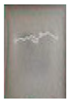 |  |  |  |  |  |  |  |  |
| Coating | Flame Retardancy Tests | ||||
|---|---|---|---|---|---|
| Burning Time with Fire/s | Burning Time without Fire/s | Flame Spread Length/mm | Specimen Pictures | Results | |
| No. 19 | 2 | 9.8 | 114–146 |  | Qualified |
| No. 25 | 2.1 | 8 | 105–129 | 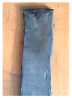 | Qualified |
| MT113 Requirement | ≤6 | ≤20 | ≤250 | - | - |
| Coating | Antistatic Resistance Tests | |||
|---|---|---|---|---|
| Specimen Pictures | Upper Surface Resistance/Ω | Lower Surface Resistance/Ω | Results | |
| No. 19 | 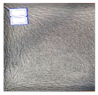 | 7.8 × 10⁴ | 3.2 × 10⁴ | <3 × 10⁸ Ω Qualified |
| No. 25 | 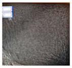 | 6.1 × 10³ | 1.3 × 10⁴ | <3 × 10⁸ Ω Qualified |
© 2020 by the authors. Licensee MDPI, Basel, Switzerland. This article is an open access article distributed under the terms and conditions of the Creative Commons Attribution (CC BY) license (http://creativecommons.org/licenses/by/4.0/).
Share and Cite
Song, H.; Liu, C.; Xue, F.; Wen, X.; Cheng, F. Experimental Study on Coal Fly Ash-Based Gas-Sealing Coating Used for Coal Mine Roadway Walls. Coatings 2020, 10, 863. https://doi.org/10.3390/coatings10090863
Song H, Liu C, Xue F, Wen X, Cheng F. Experimental Study on Coal Fly Ash-Based Gas-Sealing Coating Used for Coal Mine Roadway Walls. Coatings. 2020; 10(9):863. https://doi.org/10.3390/coatings10090863
Chicago/Turabian StyleSong, Huiping, Chunhui Liu, Fangbin Xue, Xuhui Wen, and Fangqin Cheng. 2020. "Experimental Study on Coal Fly Ash-Based Gas-Sealing Coating Used for Coal Mine Roadway Walls" Coatings 10, no. 9: 863. https://doi.org/10.3390/coatings10090863