Article

Preparation and Properties of Composite Nanoceramic NiCrBSi-TiO2/WC(Co) Coatings

1
Henan Provincial Key Laboratory of Intelligent Manufacturing of Mechanical Equipment, School of Mechanical and Electrical Engineering, Zhengzhou University of Light Industry, Zhengzhou 430002, China
2
Henan Engineering Research Center of New Energy Vehicle Light Weight Design and Manufacturing, Zhengzhou 430002, China
3
National Key Laboratory for Remanufacturing, Academy of Armored Forces Engineering, Beijing 100072, China
*
Author to whom correspondence should be addressed.
Coatings 2020, 10(9), 868; https://doi.org/10.3390/coatings10090868
Submission received: 11 March 2020 / Revised: 30 August 2020 / Accepted: 7 September 2020 / Published: 8 September 2020

Abstract

:
Using the supersonic plasma spraying (SPS) technique, the preparation of a NiCrBSi (Ni60) coating was achieved by adding nano TiO2 in Ni60 coating with WC ceramic particles. Ni60-TiO2 (Ni60T) and Ni60-TiO2/WC coating (Ni60TW) were successfully prepared. Results show that of the three, Ni60T had the best densification, the porosity of the Ni60T coating exhibited the best value of 1.3%, and also has a stronger hardness value of 890 HV. At the same time, the coating corrosion resistance, wear coefficient, and the wear morphology of Ni60T are superior to Ni60 and Ni60TW coatings. It is added TiO2 and ceramic WC(Co) in Ni-based spraying powder. The main purpose is for the nanoparticles to achieve the effect of refining the grain, which can greatly improve the coating’s hardness and toughness.

1. Introduction

In recent years, supersonic plasma spraying (SPS) is a new multi-purpose precision spraying method developed after the success of flame spraying. It is also a method used in material surface strengthening and surface modification [1,2]. SPS has a lot of rigidity, with the jet being given priority with laminar flow, surrounding air cannot easily enter and less impurities. Also, the ion impact kinetic energy on the surface of the substrate is bigger, which reduces the incomplete overlap between the ions, makes preparation of coating have A higher hardness and bonding strength, low porosity, crack, less coating quality, and good waiting times for A characteristic. These features for the preparation of ceramic powder coating have great advantages, and the technology is stable. With spraying material variety, the part deformation is small, do not change the overall performance of the parts, have received extensive attention from researchers, and is an ultra-high temperature, high speed ion spray, resulting in a dense coating with low porosity [3,4,5,6]. The spraying material is not easy to oxidize and adds wear resistance, corrosion resistance, high temperature oxidation resistance, and other properties to the substrate surface material [7,8]. This important technology has been widely in the aerospace, electronics, and automotive industries to save energy, improve product quality, extend product life, improve the efficiency of materials, and improve reusability [9]. Figure 1 Schematic diagram of SPS.
NiCrBSi (Ni60) is an allow powder with a low melting point, good flow performance, high hardness, and good organizational performance, often used for the preparation of heat resistant, corrosion resistant, oxidation resistant alloy coatings [10]. Ni60 coating exhibits excellent wear resistance, oxidation resistance, low cost, and good fracture toughness [11]. Due to its favorable qualities, it has the attention of researchers, but Ni60 compared with ceramic coating, problems such as low hardness and easy deformation cannot meet the requirements of wear resistance [12]. WC and Co metallic ceramic coating are used in the metal surface in order to improve the surface hardness, wear resistance, and corrosion resistance; however, if the proportion of the metal to ceramic in the material is not correct, the surface coating may be too brittle [13,14,15]. In this paper, the supersonic plasma spraying technology was used to create materials with Ni60 powder, nano TiO2 powder, and Co cladding WC cermet coating material preparation Ni coating material. The preparation technology and properties of the three kinds of coatings were studied.

2. Experimental Methods

2.1. Experimental Materials

Figure 2 presents an experiment using a spraying of 45# steel substrate material. The processing size was Φ 20 mm × 20 mm cylindrical specimens. Acetone and alcohol were used to remove surface oil pollution before spraying. Used 800 μm corundum sand processing was also carried out on the sample. The sample spraying equipment adopts supersonic plasma spraying equipment to prepare the coating (DH-2080, Shanghai Dahao Nanomaterial Spraying Co., Ltd., Shanghai, China). The specific technological parameters are shown in Table 1. Ni60 powder (Particle size, 15–45 μm), nano TiO2 powder (Particle size, 50–80 nm), and WC-12 wt.% Co powder (Particle size, 15–45 μm) were used as raw materials, as shown in Table 1. In order to make nano titanium oxide as a spraying material, nano titanium oxide microparticles should be prepared into aggregates. Nano TiO2 aggregate powder was prepared by the spray drying method, Table 2 contains the parameters for supersonic plasma spraying.
Metal Co coated WC ceramic powder is an important type of metal–ceramic composite powder. Metal Co coated WC ceramic powder exhibits good uniformity, dispersion, and interface adhesion between different components. These properties help achieve the purpose of composite strengthening of the coating.

2.2. Test Method

The 2q step was 0.04 and the step time was 40 s/step. The characterization of the as-cast microstructures was performed by scanning electron microscopy (SEM) (MERLIN Compact, Thuringia, Germany) with energy dispersive spectrum (EDS). SEM images were taken of the cross section of the samples. Samples were etched prior to SEM analysis using Kroll’s Reagent (92 mL deionized water, 6 mL HNO3, and 2 mL HF). The phase constituents of the porous samples were determined by X-ray diffraction (XRD) patterns exposed by an X-ray diffractometer (model 7000, Rigaku Compact, Tokyo, Japan) with Cu Kα radiation and a Ni filter. The powder sample for the XRD was prepared by smearing a thin layer of powder on a glass plate. The glass plate had previously been coated with paraffin wax to allow for good adhesion. The XRD analysis was carried out at a voltage of 40 kV and 40 mA within diffraction angles ranging from 20° to 80° at a scanning speed of 8°·min−1. The hardness was measured by an indention method with an HVS-1000 digital display Vickers (Beijing Jintaike Instrument Testing Instrument Co., Ltd., Beijing, China).
Corrosion tests were carried out on coatings, the working electrode was exposed to an area of 1 cm2. Electrolytes used were NaCl (3.5 wt.%) aqueous solution and NaCl immersion experiment (120 h). Potentiodynamic polarization curves were measured with a potential sweep rate of 0.01 mV/s from −1 to 1.5 V in all solutions open to air at 298 Kafter immersing the specimens with half-hour, when the open-circuit potentials became almost steady.
Using the fretting friction and wear testing machine (SRV-I, Optimol Grease Company, München, Germany), a composite nanoceramic coating sample was prepared in the form of a disk (high: 7.8 mm, diameter: 24 mm). Experiments were carried out using GCr15 ball as grinding material, 60 N load, friction time of 30 min, and two friction conditions, namely, dry friction.

3. Results and Discussion

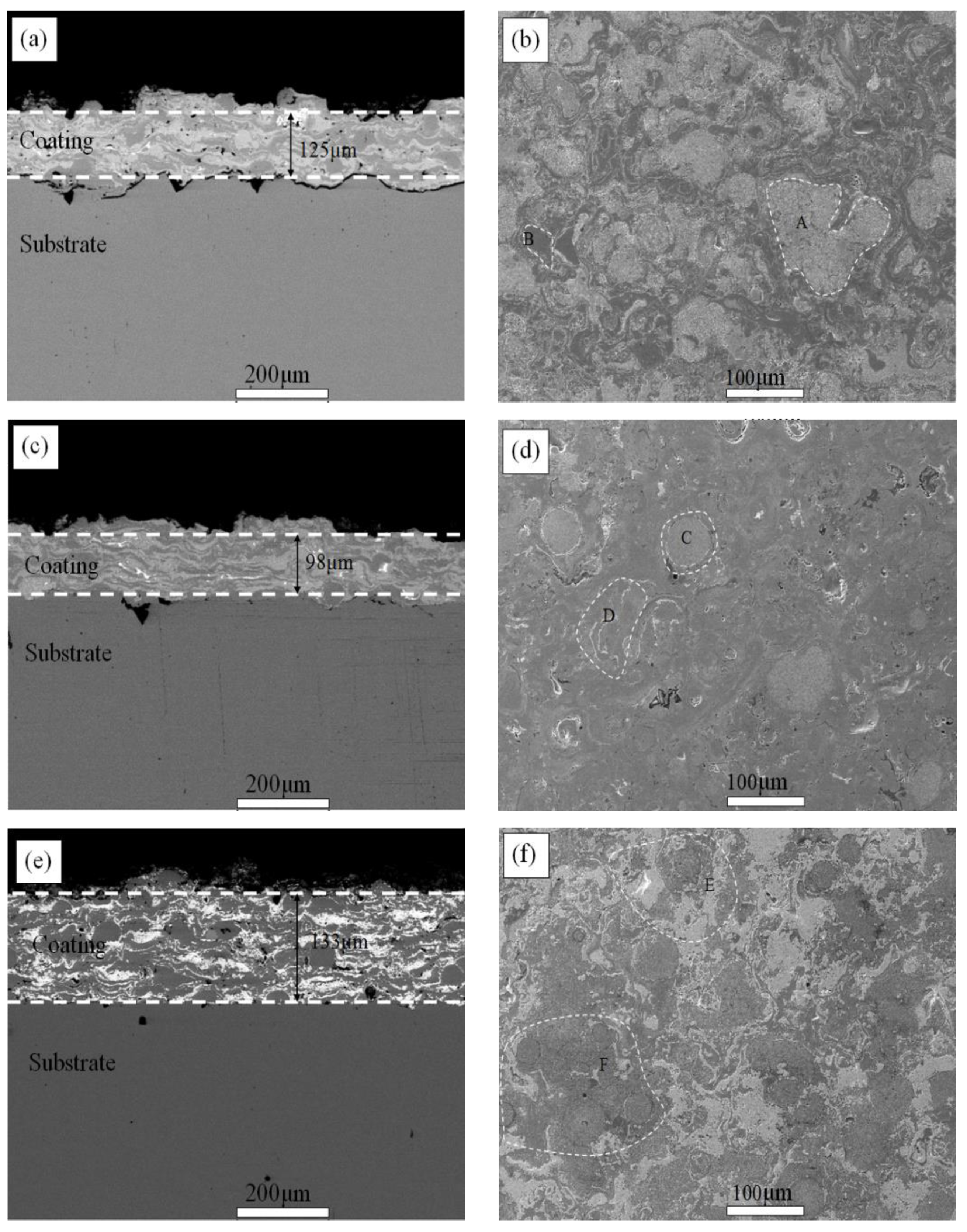
3.1. Microstructure of Coatings

The porosity of the three sample coatings was tested by Image J2X porosity software (version V2.1.4.7), and the test results were 1.5% (Ni60), 1.35% (Ni60T), and 1.6% (Ni60TW), respectively. The prepared coating surface was dense. Ni60T had the best densification, which is probably due to gaps in the coating having been filled with nanoparticles. Figure 3a shows the cross-section morphology of the Ni60 coating. It can be seen that the coating thickness is about 125 μm after spraying. Obvious cracks appear between the coating and the substrate caused by insufficient preheating temperature of the substrate. It can also be seen from the section of the coating in Figure 3a that there are some pores and unmelted particles. The reasons for pores in Ni60 spraying may be: (1) shrinkage and stress effects caused by solidification of particles, (2) during spraying, sputtering occurred when the flame flows impact on the surface of the substrate, resulting in areas of the substrate surface not being completely filled by the spray particles, and (3) pores may exist in the used raw material powder.
The uneven structure of cambium in the whole section is caused by the continuous impact of powder on the surface of the substrate in the process of melting and atomization, and the continuous superposition, which results in the combination of the coating and substrate as a mechanical combination. Figure 3b shows the surface morphology of Ni60 coating after polishing and corrosion. It can be seen from the Figure 3b that the surface is compact, spraying particles resulted in a good deposition effect in the areas labeled A and B; however, the surface presents and island morphopogy. These islands are caused by the different melting temperatures of particles in Ni60 powder.
Figure 3c shows the microstructure of the Ni60T coating cross-section. After adding 15 wt.% TiO2 nanoparticles, an inhomogeneous stratified structure remains. The layered Ni60 is about 98 μm in depth. Porosity and not melt particles are gaining in number, which may be related to nanotitanium oxide during melting process. As a result, the filling effect between particles on the surface from Figure 3d in the spherical structure is reduced and the TiO2 powder particles did not melt, this is evident in the areas labeled C and D. Figure 3e is a sample Ni60TW coating microstructure, after adding 35% WC (Co), including the WC for Co WC cladding structure. The coating thickness is about 133 μm. It can be seen from the diagram that particles also appeared in pores and did not melt. This may be due to the process of spraying, as the melting reaction could have been caused by a different temperature in the spraying. The difference between the surface can be seen from the Figure 3f. The surface appears to have a smooth porphyritic morphology, which is present in the areas labeled E and F. Different coating thickness affects the hardness of the material. It can be seen from Figure 4 in the paper that the change of hardness is consistent with the change of thickness, which is the minimum thickness and the maximum hardness.

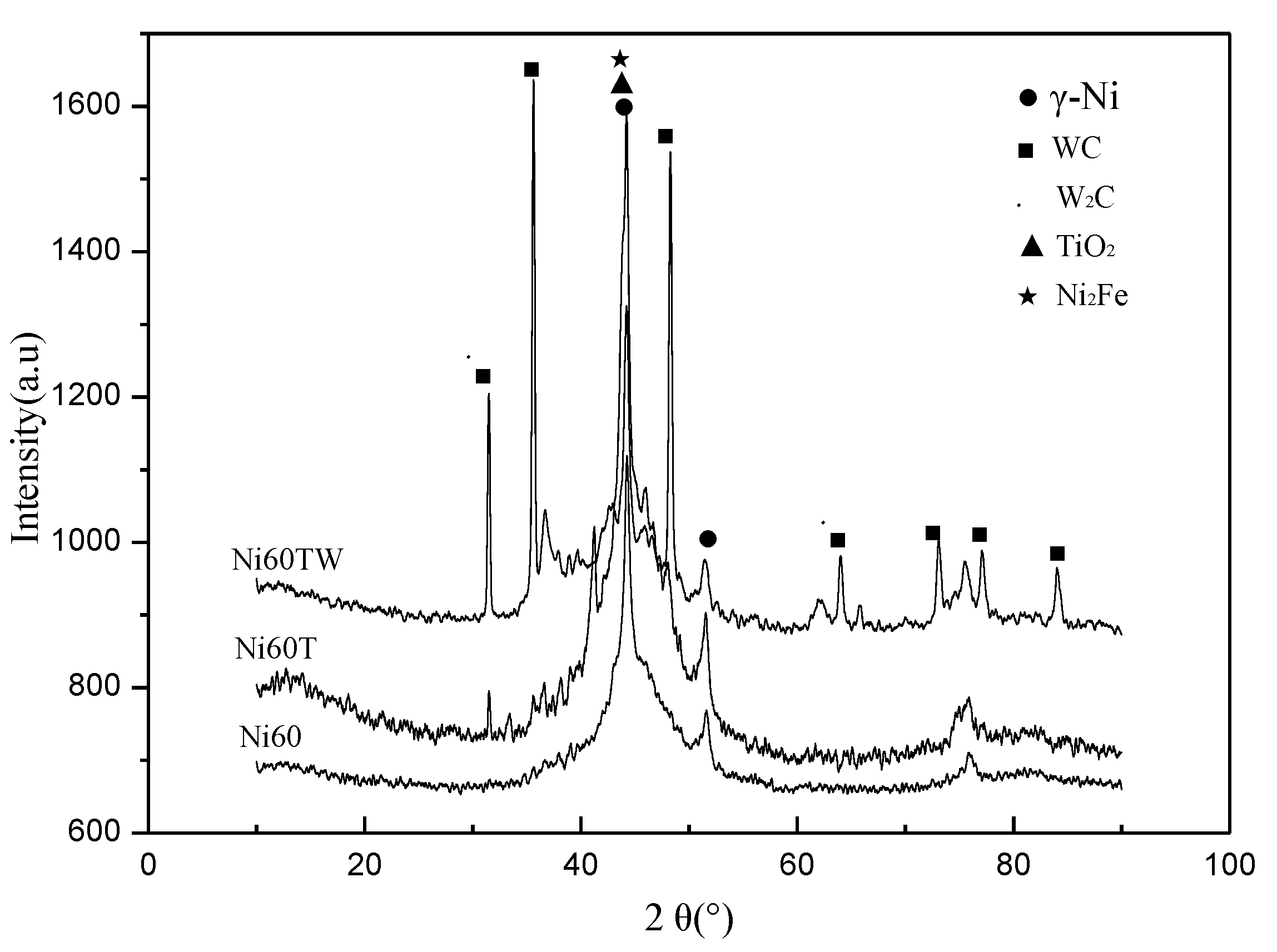
3.2. XRD of Coatings

Figure 4 summarizes the XRD spectra of three coatings, Some of the major phases in the coating are marked, such as, γ-Ni and Ni2Fe, TiB2, TiO2, WC, and W2C compounds; however, the appearance of W2C phase was due to the WC evolution decarburization reaction that happened in the process of spraying, W2C phase can improve the hardness of coating, and the wear resistance of the coating, but the coating did not appear in the WC-Co, Co elements, this was because the molten metal Co was deposited on the matrix. The solidification speed was too fast during the supersonic plasma spraying; therefore, some Co was changed into being amorphous and the Co peak width was not obvious. TiO2 phases may be due to the presence of unmelted TiO2 particles in the coating.

3.3. Hardness of Coatings

The micro-hardness distribution of the coating along the direction of the substrate was tested. As shown in Figure 5, the hardness of Ni60 coating was the lowest, while the hardness of Ni60T was the highest. The hardness of Ni60T and Ni60TW were higher than that of 45# steel (HV695). The spraying process affects the microhardness of the coatings. The deposit after melting or softening of the particles to deposit first pancake grain hit the compaction effect, it appeared to maintain a different degree of strain hardening effect, and was made near the interface of coating organization than near the particle deformation spread out on the surface of the coating. This is better as it is dense, with less holes, and close to the hardness of 45# steel substrate is reduced, this is because at the start of the spray, it is not even the micro cracks, pores, etc. caused by the defects. The decrease of hardness value and the big fluctuation are caused by being closer to the surface of the coating, the loose and uneven structure, and the increase of coating defects. The non-uniformity of the tissues in the coating resulted in the differences of surface hardness due to the pores. Adding nano TiO2 particles caused dispersion strengthening in the Ni60 mixed powder, leading to the maximum hardness value.

3.4. Corrosion Performance of Coatings

Three samples were left in NaCl solution with a concentration of 3.5 wt.% for 120 h. Figure 6 presents the coating section microscopic scanning images. In Figure 6a, Ni60 coating and substrate interface cracking appeared due to salt corrosion. In Figure 6b,c, Ni60T and Ni60TW show no obvious corrosion products after the NaCl bath. Hybride coatings provide a protective effect that prevents the corrosion reaction and improves the corrosion resistance of coating. They can also cause the coating surface to have a smooth and uniform corrosion, or corrosion products for selective corrosion [2]. Figure 6d shows the electrochemical corrosion curve of the three coatings in the corrosive medium NaCl solution. According to the curve, the self-corrosion potential moves forward to a certain extent, the corrosion current density decreases significantly, and the corrosion resistance of the coatings increases. The Ni60T coating has the best corrosion resistance.

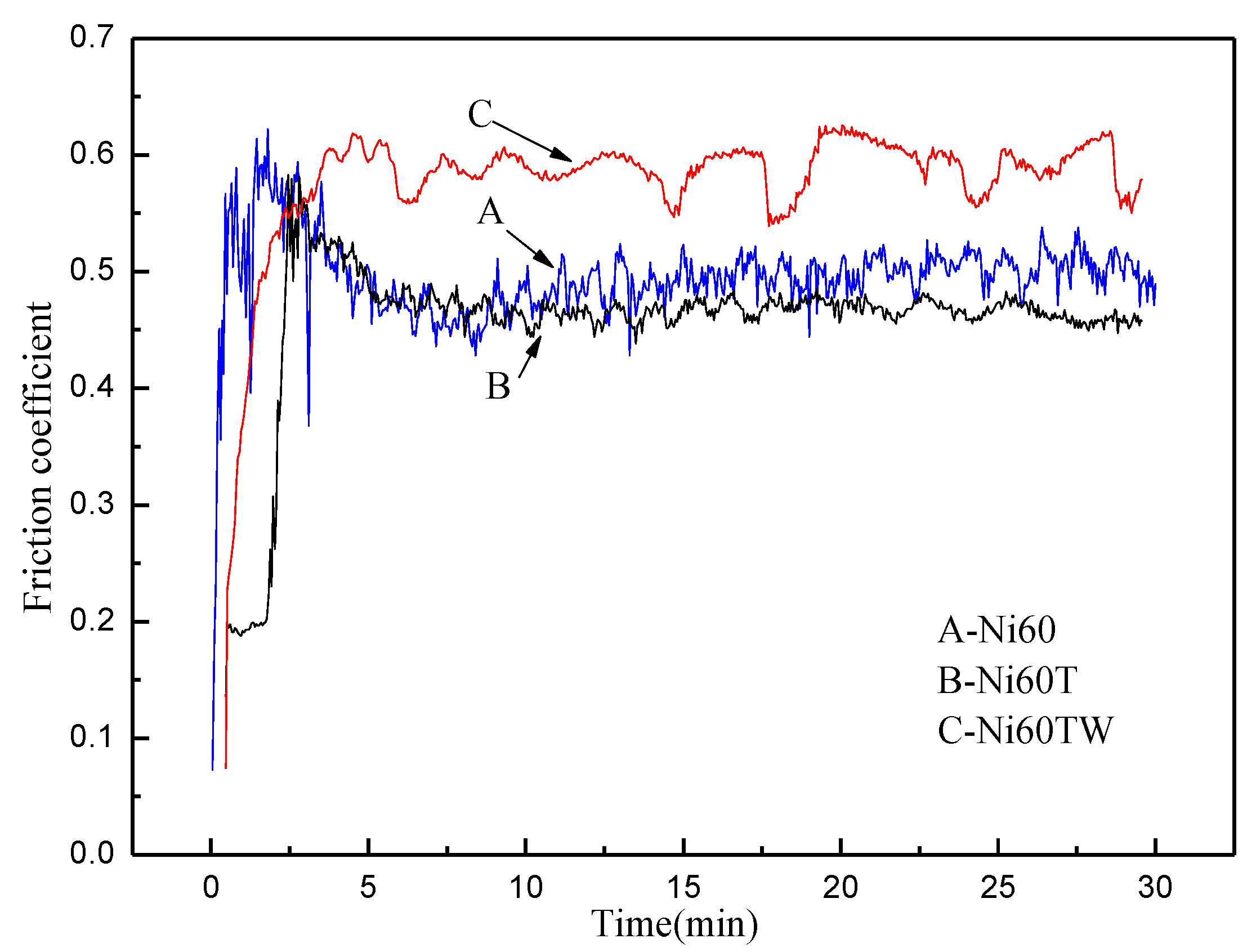
3.5. Friction Coefficient of Coatings

Figure 7 shows the three kinds of coating surface galling experiments. Seen from the Figure 7, the friction coefficient of Ni60T was minimum at 0.45. The Ni60 friction coefficient was 0.5, slightly larger than Ni60T. The Ni60TW has a coefficient of 0.6. This may be due to the nanometer TiO2, it was added to a certain extent, and filled clearances of in the Ni60 powder. The density is also improved and there is increased wear resistance. On the contrary, the increase of WC particles in the matrix in the form of unmelted particles along with an uneven coating leads to higher friction coefficient and wear resistance is reduced. It can also be seen from the friction coefficient curve of Ni60TW in Figure 7 that the curve is uneven, which is due to the existence of unmelted WC particles in the coating.

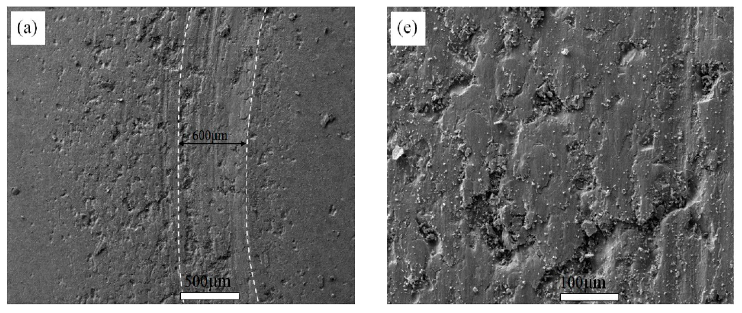
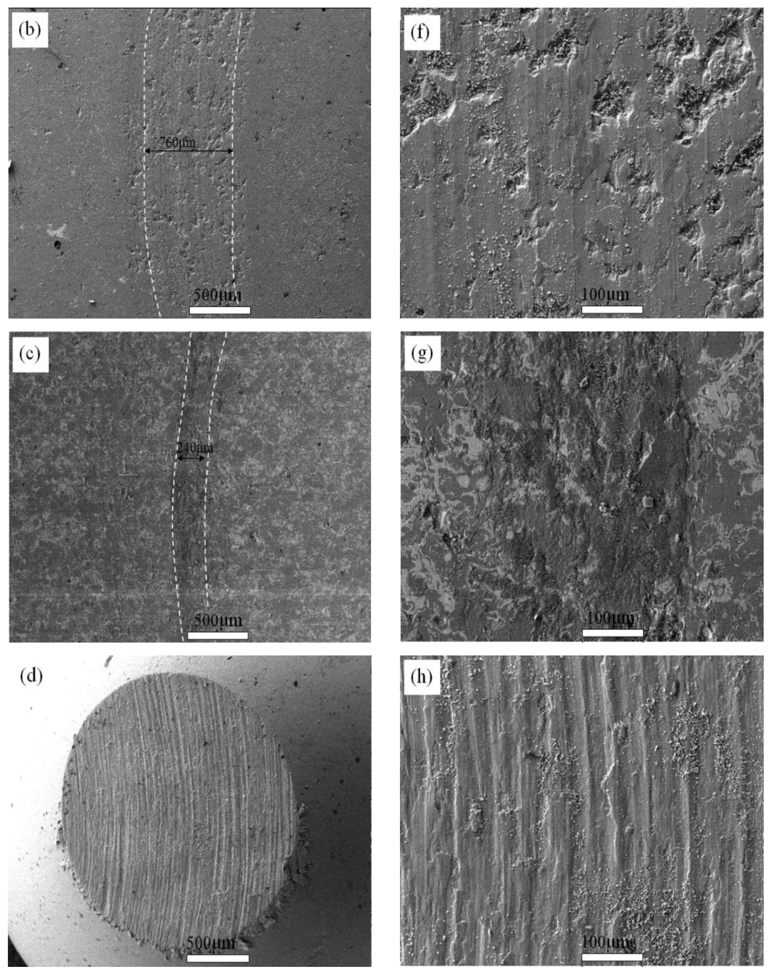
3.6. Wear Morphology of Coating

Figure 8 shows the friction and wear morphologies of the three coatings under 60 N loading. Figure 8a displays the Ni60 wear surface morphologies. Figure 8e is magnification of the Ni60 wear area. There are abrasive chips and pits on the surface, mainly with abrasive wear mechanism. Figure 8b is the Ni60T coating wear surface topography. From the diagram, it can be seen that the surface wear trace area increases up to 760 μm. This is due to the hardness of the Ni60T coating surface, which leads to more wear and tear on the surface of the friction pair. Figure 8g is a larger view of the wear area of Ni60T. The surface is smooth, and there is no pit-like morphology. The primary feature is an adhesive wear mechanism. Figure 8c is the surface of the wear of the Ni60TW coating. The wear trace is 240 μm. The wear trace appeared to quickly reduce; this is because the coating surface hardness is low, and thus, the friction pair of the surface caused the grinding crack depth increase. See from Figure 8f, on the surface there exhibits certain furrow pits of abrasive grain and morphology, characterized by abrasive wear and fatigue wear mechanism. Figure 8d shows the surface wear morphology of the Ni60T friction pair ball (GCr15), with the edge of the worn surface falling off, and the obvious furrow morphology in Figure 8h, which also reflects the reason why the coating hardness of Ni60T surface is larger and the friction coefficient is smaller.

3.7. Idea of Coatings Preparation

There are two added TiO2 and ceramic WC (Co) compounds in Ni-based spraying powder. The main purpose is for the nanoparticles to achieve the effect of refining the grain, which can greatly improve the coating’s hardness and toughness. Metal Co cladding WC can be realized between different phase with good uniformity and dispersion. In the process of powder coating melt, the interface bonding strength of ceramic powder and metal phase can improve along with the distribution uniformity, achieving multiple elements of different mechanisms to give an overall composite reinforcement effect. Figure 9 is a schematic diagram of coating formation.

4. Conclusions

Based on the Ni60 coating, through the continuous addition of nanoparticles and hard phases in the coating raw materials, the performance of the prepared coating surface was compared and analyzed. The following conclusions were obtained:
  • Nano TiO2 particles were added into Ni60 raw materials to obtain a dense coating surface, which improved the corrosion resistance and wear performance;
  • Nano TiO2 particles improve coatings homogeneity;
  • The raw material is Ni60T with the addition of hard phase WC particles; results in a dense coating surface. However, the porosity of the coating is inhomogeneous, and the corrosion resistance and wear resistance of the coating are decreased also.

Author Contributions

Conceptualization, X.W. and Z.X.; methodology, X.W.; software, X.W.; validation, Z.X.; formal analysis, X.W.; investigation, X.W.; resources, X.W.; data curation, X.W.; writing—original draft preparation, X.W.; writing—review and editing, Z.X.; visualization, X.W.; supervision, Z.X.; project administration, X.W.; funding acquisition, X.W. All authors have read and agreed to the published version of the manuscript.

Funding

This work is financially supported by the National Science Foundation of China (No. 51775554) and Dr Fund of Zhengzhou University of Light Industry (No. 2018BSJJ011). Foundation of Key Laboratory of National Defense Science and Technology (No. 6142005200302) is gratefully acknowledged and equipment pre-research field fund project (61409230611). Natural Science Foundation of Henan Province.

Conflicts of Interest

The authors declare no conflict of interest.

References

  1. Wang, X.S.; Xing, Z.G.; Liu, Y.P.; Hou, J.J.; Liu, K. Composite ceramic-Ni60 coating fabricated via supersonic plasma spraying. Chin. J. Phys. 2019, 61, 72–79. [Google Scholar] [CrossRef]
  2. Wen, Z.H.; Bai, Y.Y.; Huang, J.F. Corrosion resistance of vacuum re-melted Ni60-NiCrMoY alloy coatings. J. Alloys Compd. 2017, 711, 659–669. [Google Scholar] [CrossRef]
  3. Guével, L.Y.; Grégoire, B.; Cristóbal, M.J.; Feaugas, X.; Oudriss, A.; Pedraza, F. Dissolution and passivation of aluminide coatings on model and Ni-based superalloy. Surf. Coat. Techol. 2019, 357, 1037–1047. [Google Scholar] [CrossRef]
  4. Das, P.; Paul, S.; Bandyopadhyay, P.P. Tribological behaviour of plasma sprayed diamond reinforced molybdenum coatings. Int. J. Refract. Met. Hard 2019, 78, 350–359. [Google Scholar] [CrossRef]
  5. Tan, A.W.; Sun, W.; Bhowmik, A.; Lek, J.Y.; Marinescu, I.; Li, F.; Khun, N.W.; Dong, Z.L.; Liu, E.J. Effect of coating thickness on microstructure, mechanical properties and fracture behaviour of cold sprayed Ti6Al4V coatings on Ti6Al4V substrates. Surf. Coat. Technol. 2018, 349, 303–317. [Google Scholar] [CrossRef]
  6. Qiao, X.; Wang, Y.M.; Weng, W.X.; Liu, B.L.; Li, Q. Influence of pores on mechanical properties of plasma sprayed coatings: Case study of YSZ thermal barrier coatings. Ceram. Int. 2018, 44, 21564–21577. [Google Scholar] [CrossRef]
  7. Das, P.; Paul, S.; Bandyopadhyay, P.P. Plasma sprayed diamond reinforced molybdenum coatings. J. Alloys Compd. 2018, 767, 448–455. [Google Scholar] [CrossRef]
  8. Nazir, M.H.; Khan, Z.A.; Saeed, A.; Braun, V.W. Experimental analysis and modelling for reciprocating wear behaviour of nanocomposite coating. Wear 2018, 416–417, 89–102. [Google Scholar] [CrossRef]
  9. Vashishtha, N.; Sapate, S.G.; Bagde, P.; Rathod, A.B. Effect of heat treatment on friction and abrasive wear behaviour of WC-12Co and Cr3C2-25NiCr coatings. Tribol. Int. 2018, 118, 381–399. [Google Scholar] [CrossRef]
  10. Deen, K.M.; Afzal, M.; Liu, Y.; Farooq, A.; Ahmad, A.; Asselin, E. Improved corrosion resistance of air plasma sprayed WC-12%Co cermet coating by laser re-melting process. Mater. Lett. 2017, 191, 34–37. [Google Scholar] [CrossRef]
  11. Chen, J.B.; Dong, Y.C.; Wan, L.; Yang, Y.; Chu, Z.H.; Zhang, J.X.; He, J.; Li, D.Y. Effect of induction remelting on the microstructure and properties of in situ TiN-reinforced NiCrBSi composite coatings. Surf. Coat. Technol. 2018, 340, 159–166. [Google Scholar] [CrossRef]
  12. Luo, X.T.; Smith, G.M.; Wang, Y.; Gildersleeve, E.; Sampath, S.; Li, C.J. Cracking induced tribological behavior changes for the HVOF WC-12Co cermet coatings. Ceram. Int. 2019, 45, 4718–4728. [Google Scholar] [CrossRef]
  13. Wang, X.Y.; Zhou, S.F.; Dai, X.Q.; Lei, J.B.; Guo, J.B.; Gu, Z.J. Evaluation and mechanisms on heat damage of WC particles in Ni60/WC composite coatings by laser induction hybrid cladding. Int. J. Refract. Met. Hard 2017, 64, 234–241. [Google Scholar] [CrossRef]
  14. Ma, Q.S.; Li, Y.J.; Wang, J.; Liu, K. Microstructure evolution and growth control of ceramic particles in wide-band laser clad Ni60/WC composite coatings. Mater. Des. 2016, 92, 897–905. [Google Scholar]
  15. Wu, Y.S.; Zeng, D.C.; Liu, Z.W.; Qiu, W.Q.; Zhong, X.C.; Yu, H.Y.; Li, S.Z. Microstructure and sliding wear behavior of nanostructured Ni60–TiB2 composite coating sprayed by HVOF technique. Surf. Coat. Technol. 2011, 206, 1102–1108. [Google Scholar] [CrossRef]
Figure 1. Schematic diagram of supersonic plasma spraying (SPS).
Coatings 10 00868 g001
Figure 2. Microscan of raw material, (a) Ni60, (b) TiO2, (c) WC-12Co.
Coatings 10 00868 g002
Figure 3. Microstructure of composite ceramic coatings, (a,b) Ni60, (c,d) Ni60T, (e,f) Ni60TW.
Coatings 10 00868 g003
Figure 4. XRD spectrum of composite ceramic coatings.
Coatings 10 00868 g004
Figure 5. Hardness change of composite ceramic coatings.
Coatings 10 00868 g005
Figure 6. Corrosion performance of composite ceramic coatings: (a) Ni60; (b) Ni60T; (c) Ni60TW; (d) Eelectrochemical corrosion curve of the three coatings.
Coatings 10 00868 g006
Figure 7. Friction coefficient of composite ceramic coatings.
Coatings 10 00868 g007
Figure 8. Wear morphology of composite ceramic coatings, (a,e) Ni60, (b,g) Ni60T, (c,f) Ni60TW, (d,h) 45# steel.
Coatings 10 00868 g008aCoatings 10 00868 g008b
Figure 9. Idea of composite ceramic coatings preparation.
Coatings 10 00868 g009
Table 1. Raw materials used for 45# steel-Ni60 coating.
45# SteelCMnSiCrNiFe
Content0.450.650.3<0.25<0.25Bal.
Ni60 CoatingCrSiBCFeNi
Content16.04.03.51.0<5Bal.
Table 2. Process parameters of the composite ceramic-Ni60 coating obtained via the supersonic plasma spraying (SPS) technique.
Number of CoatingParameter
Spraying current (A)360
Spraying voltage (V)120
Argon gas flow (m3/h)3.6
Hydrogen gas flow (m3/h)0.25
Spraying distance (mm)120
Powder feed rate (g/min)35
Nitrogen gas flow (m3/h)0.6

