Article

Inkjet Printing of Highly Sensitive, Transparent, Flexible Linear Piezoresistive Strain Sensors

Department of Electronic Engineering, Cheng Shiu University, Kaohsiung City 833, Taiwan
Coatings 2021, 11(1), 51; https://doi.org/10.3390/coatings11010051
Submission received: 6 December 2020 / Revised: 31 December 2020 / Accepted: 2 January 2021 / Published: 5 January 2021
(This article belongs to the Section Thin Films)

Abstract

:
Flexible strain sensors are fabricated by using a simple and low-cost inkjet printing technology of graphene-PEDOT:PSS (poly(3,4-ethylenedioxythiophene):poly(styrenesulfonate)) conductive ink. The inkjet-printed thin-film resistors on a polyethylene terephthalate (PET) substrate exhibit an excellent optical transmittance of about 90% over a visible wavelength range from 400 to 800 nm. While an external mechanical strain is applied to thin-film resistors as strain sensors, a gauge factor (GF) of the piezoresistive (PR) strain sensors can be evaluated. To improve the GF value of the PR strain sensors, a high resistive (HR) path caused by the phase segregation of the PEDOT:PSS polymer material is, for the first time, proposed to be perpendicular to the PR strain sensing direction. The increase in the GF with the increase in the HR number of the PR strain sensors without a marked hysteresis is found. The result can be explained by the tunneling effect with varied initial tunneling distances and tunneling barriers due to the increase in the number of HR. Finally, a high GF value of approximately 165 of three HR paths is obtained with a linear output signal at the strain range from 0% to 0.33%, further achieving for the inkjet printing of highly sensitive, transparent, and flexible linear PR strain sensors.

1. Introduction

Flexible strain sensors have recently attracted great interest because of their various potential applications, such as for human motion detection [1], personal health monitoring [2], acoustic vibration detection [3], and human-machine interfaces [4]. In general, various strain sensors are mainly divided into three types: capacitive [5], piezoelectric [6], and piezoresistive (PR) [7,8,9]. Among them, the PR-type strain sensors has always been popular owing to their simple structure and easily reading output signal. Moreover, the gauge factor (GF) is often used to evaluate the sensitivity of the PR strain sensors and can be expressed as the ratio of relative change in electrical resistance to the applied strain (ε). However, conventional strain sensors composed of semiconductor slabs suffer from disadvantages, including poor flexibility, multi-staged fabrication steps, and high fabrication cost due to their brittle sensing materials. For example, the silicon-based sensor fabrication process requires sophisticated equipment operated in a clean room. These disadvantages also confine their application and development for arbitrarily curved surfaces. Inkjet printing, which accurately deposits liquid materials on flexible substrates in a noncontact method, has been widely used for the implementation of flexible PR strain sensors due to the benefits of low material consumption, low-cost printed equipment, and easy fabrication [10]. The inkjet printed strain sensors based on a liquid conductive polymer poly(3,4-ethylenedioxythiophene):poly(styrenesulfonate) (PEDOT:PSS) material has been reported and demonstrated to be a lower GF value of approximately 2.48 [11]. To improve the sensitivity of flexible PR strain sensors, polymer-based composites are also promising PR materials [12,13,14,15]. For example, graphene-PEDOT:PSS composites have exhibited a high GF of approximately 22 [15]. To date, several fundamental sensing mechanisms, such as the tunneling effect [8,9], the disconnection between overlapped nanomaterials [16], and the formation of nanoscale cracks [17], have been reported with a higher GF value for the PR strain sensors. However, a higher GF could respond to a high nonlinearity strain sensor. For example, based on the formation of nanoscale cracks, an ultrahigh sensitive (GF 2000) strain sensor possesses a nonlinearity PR property [17]. The PR strain sensors usually cause larger hysteresis behavior than the capacitive strain sensors [16]. Although a higher sensitivity is quite important for the flexible PR strain sensors, the requirements that simultaneously satisfy a high optical transparency, a lower hysteresis, and a good linearity are still a grand challenge.
This study, therefore, employs graphene-PEDOT:PSS conductive ink to fabricate flexible PR strain sensors by a simple low-cost inkjet printing technology. The inkjet printing technology, which is a material-saving deposition method used in liquid inks, is widely believed to be one of the most promising ways to develop flexible electronics [18]. The GF is also measured to evaluate the PR responses of the flexible strain sensors. Furthermore, to realize the high sensitive and flexible PR strain sensors, a high resistive (HR) path is proposed for the increase in GF and the thin film resistor is printed on a polyethylene terephthalate (PET) flexible substrate. Besides, the requirements regarding optical transparency, hysteresis behavior, and PR linearity are also discussed in the following sections.

2. Materials and Methods

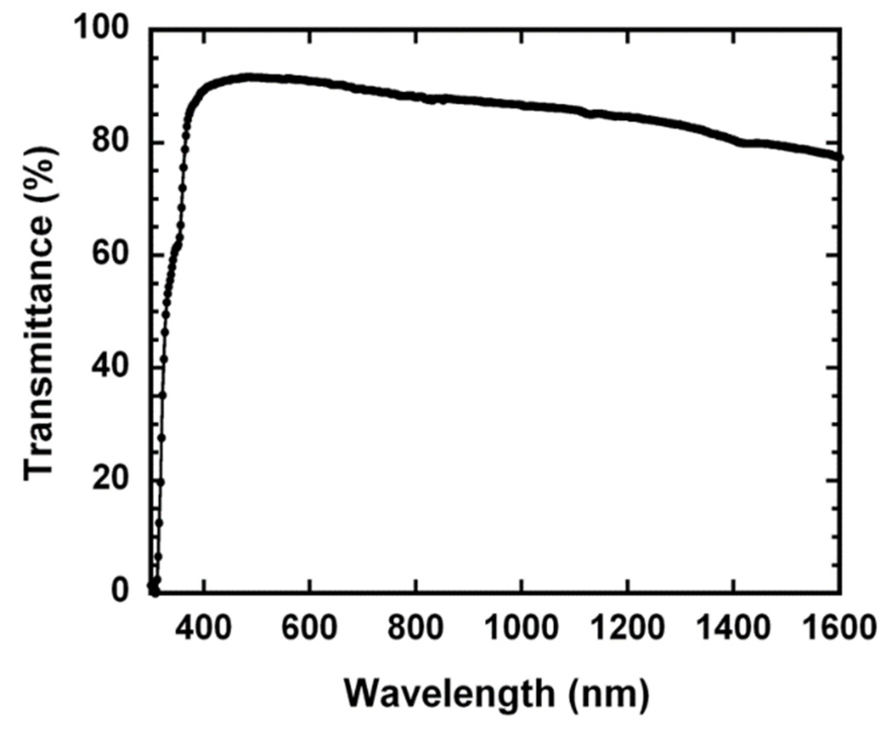
The commercial inkjet printing (XP-202, Epson, Suwa, Japan) filled with liquid conductive inks was used to fabricate the +-shape PR strain sensors, as shown in Figure 1a. The +-shape pattern was constructed from two shapes of horizontal and vertical I. The dimensions of horizontal and vertical I shapes were printed to be 10 mm × 3 mm for the sensing resistance and 1 mm × 12 mm for the generation of the HR path, respectively. In Figure 1b, the output signal of the sensing PR change was measured from A and B: two terminals of the horizontal I shape once the HR path was generated in the vertical I shape. In other words, the operation of the +-shape PR strain sensors was divided into two steps: (i) a high current produced by sweeping an applied voltage from 0 to 50 V can drive the resistance in the vertical I shape switching from the low resistance to the high resistance, and (ii) the sensing PR signal can be outputted from the A and B terminals of the horizontal I shape. The liquid conductive inks are composed of graphene-PEDOT:PSS composites. The graphene-PEDOT:PSS conductive inks were produced by using the electrolytic exfoliation method [19,20]. The composition of the conductive inks was confirmed by using a micro-Raman system (LabRAM HR, Horiba Jobin Yvon, Longjumeau, France) with an excitation energy of 2.33 eV (laser wavelength: 532 nm). The spectral features of the graphene-PEDOT:PSS composites were reported in previous literature [21], clearly revealing that the graphene material had lower defect states due to the presence of the D peak at ~1330 cm−1 [22], the multilayer graphene material was observed from the 2D peak at ~2670 cm−1 less than the G peak [23], and the peak positions of the symmetric and asymmetric Cá = Câ band of the PEDOT were confirmed [24] (not shown here). The process steps of the flexible PR strain sensors were described as follows. First, the inkjet-printed +-shape thin-film resistor on a PET substrate, serving as the flexible PR strain sensor, was heated at the temperature of 100 °C for 15 min to remove all the residual water. Then, to improve the sensitivity of the flexible PR strain sensors, a HR path caused by the phase segregation of the PEDOT:PSS polymer material [21,25] was, for the first time, designed to be perpendicular to the strain sensing direction. Figure 1c,d exhibited the strain sensor pattern with two and three HR paths, respectively. Besides, the optical transmittance over a large wavelength range from 300 to 1600 nm was measured with a ultraviolet-visible-near-IR (UV-vis-NIR) spectrophotometer (U4100, Hitachi High-Technologies Corporation, Tokyo, Japan), as shown in Figure 2, further demonstrating that the optical transmittance of approximately 90% in the visible range from 400 to 800 nm was obtained. Finally, all current-voltage (I-V) characteristics of the flexible PR strain sensors were measured at room temperature with a Keithley 2400 source meter (Cleveland, OH, USA).

3. Results and Discussion

3.1. Electrical Characteristics of Flexible PR Strain Sensors

Figure 3a,b shows the measurement setup of flexible PR strain sensors and relation between the applied ε and the arc radius (r), respectively. The arc r fixture applying ε to the strain sensor is easily built by using a 3D printer [26]. Thus, the different arc r fixtures can provide various applied ε values for the flexible strain sensor. The relation between the applied ε and the arc r can be expressed as follows [7]:
ε = h 2 r ,
where h is the thickness of the PET substrate (=100 ìm), and r is the arc radius of a 3D printing fixture. Based on the calculations of Equation (1), the different arc r values of 45, 35, 25, and 15 mm correspond to the applied å of 0.11%, 0.14%, 0.20%, and 0.33%, respectively. Figure 4a shows that the I-V characteristics of the flexible PR strain sensors are measured with one full cycle of applying various ε values from 0% to 0.33% and then releasing various ε values from 0.33% to 0%. Based on the slope of the I-V curves corresponding to Figure 4a, the relation between normalized resistance change (ΔR/R0) and applied ε with one full strain cycle can be plotted in Figure 4b, further demonstrating the resistance increase in the PR strain sensor with the increase in the applied ε and a lower hysteresis behavior existing in the PR strain sensor. Similar I-V characteristics and the relation between ΔR/R0 and applied ε are also observed with a lower hysteresis behavior in the PR strain sensors having the HR paths (not shown here). These results could be explained by a strong interfacial binding between the graphene and PEDOT:PSS materials [16].

3.2. Sensitivity of Flexible PR Strain Sensors

In order to evaluate the sensitivity of the flexible PR strain sensors, the GF is described using the following expression:
GF = Δ R R 0 ε
where R0 is the initial resistance of the strain sensor without applied ε, and ΔR is the change of the resistance of the strain sensor under applied ε. While different ε values are applied to the flexible PR strain sensors, the relation between the ΔR/R0 and applied ε is measured to determine the GF values based on Equation (2). To increase the GF value of the flexible PR strain sensors, the HR paths caused by the current-induced PEDOT:PSS phase segregation [21,25] are, for the first time, designed to be perpendicular to the strain sensing direction. Figure 5 shows a linear relation between ΔR/R0 and applied ε for zero, one, two, and three HR paths and the increase in the GF with the increase in the HR number, clearly exhibiting the flexible PR strain sensors, with a linear output signal at the strain range from 0% to 0.33%. The higher GF values of 72, 97, and 165 extracted from the slope of the linear relations between R/R0 and applied ε represent the generated one, two, and three HR paths, respectively. Compared with the GF value of 43 without a HR path, i.e., the zero HR path, the highest GF value of approximately 165 is found for three HR paths. The log-linear I-V characteristics, i.e., the conversion of the I-V curves in Figure 6a from the linear to the logarithmic scale, of three generated HR paths from the low-resistance state to the high-resistance state are shown in Figure 6b, further demonstrating the phase-segregation behavior of resistive switching in the PEDOT:PSS material caused by a high switching current [25].

3.3. Possible Mechanism of Highly Sensitive PR Strain Sensors

For zero, one, two, and three HR paths of the flexible PR strain sensors, the increase in the GF values with the increase in the initial resistance R0 is found and simultaneously plotted in an exponential fitting line, as shown in Figure 7. The results imply that the R0 increase can be attributed to the tunneling effect with the varied initial tunneling distances (d0) and tunneling barriers (φ) due to the generation of the HR paths. To further verify the highly sensitive sensing characteristics of the flexible PR strain sensors, the relative resistance (RS/R0) due to the change from d0 to dS before and after applied ε can be expressed as follows [8,9]:
R S R 0 = d S d 0 exp [ γ ( d S d 0 ) ]
where RS and dS are the resistance of the strain sensor and the tunneling distance after applied ε, respectively, and ã is described as
γ = 4 π 2 m ϕ h
where h is Plank’s constant, m is the electron mass, and φ is the tunneling barrier. The applied ε can be expressed as
ε   =   d S d 0 d 0
Substituting Equation (5) into Equation (3), the RS/R0 can be further described using the following expression:
ln R S R 0 = ln ( 1 + ε ) + γ × d 0 × ε
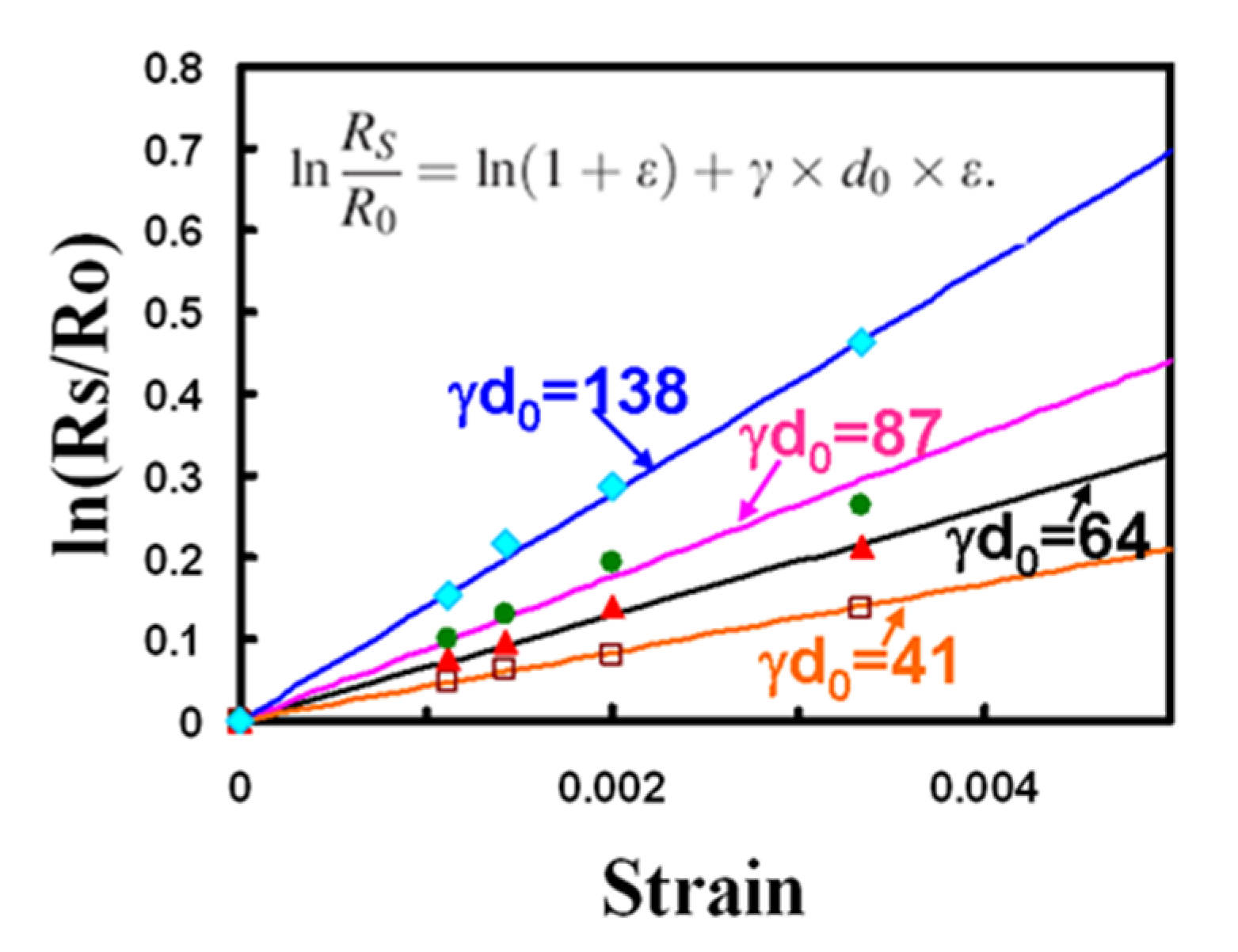
Based on Equation (6), the calculated ln(RS/R0) dependence of the applied ε can meet our experimental results with varied d0 and γ values, as shown in Figure 8, further suggesting that the possible mechanism of the highly sensitive strain sensor can be explained by the change of d0 and φ due to the generation of the HR paths. Finally, the GF value of approximately 165 of three HR paths is accomplished for the inkjet printing of the high-sensitive strain sensors. However, an ultrahigh sensitive (GF > 200) issue regarding the use of greater than three HR paths certainly needs further research. Besides, the graphene-PEDOT:PSS composite possessing a temperature coefficient of resistance (TCR) value higher than 0.06% per degree Celsius has been used for thermal sensors [27], and the transport mechanism of the PEDOT:PSS material appears to be anisotropic [28]. Similarly, other issues for the flexible PR strain sensors regarding the TCR and biaxial sensing directions, i.e., longitudinal and transverse GFs, still need a deeper understanding in the future.

4. Conclusions

The simple and low-cost inkjet printing of graphene-PEDOT:PSS conductive ink has been proposed for the fabrication of the flexible PR strain sensors. The printed thin-film resistors on a PET flexible substrate exhibit an excellent optical transmittance of approximately 90% in the visible range from 400 to 800 nm. To improve the GF value of the flexible PR strain sensor, a HR path caused by the phase segregation of the PEDOT:PSS polymer material is, for the first time, proposed to be perpendicular to the strain sensing direction. The increase in the GF with the increase in the HR number of the PR strain sensors with a lower hysteresis is found. The results can be explained by the tunneling effect with the change of the two tunneling parameters of d0 and γ due to the generation of the HR paths. Finally, the higher GF value of approximately 165 of three HR paths is obtained with a linear output signal at the strain range from 0% to 0.33%, further fulfilling for the inkjet printing of high sensitive, transparent, and flexible linear PR strain sensors.

Funding

This research was supported by the Ministry of Science and Technology (MOST) under Contract No. MOST 109-2221-E-230-003.

Data Availability Statement

Data is contained within the article.

Acknowledgments

The author would like to thank S. C. Cai, Y. C. Huang, and J. W. Zhuang for their assistance in the electrical measurements.

Conflicts of Interest

The author declares no conflicts of interest.

References

  1. Yamada, T.; Hayamizu, Y.; Yamamoto, Y.; Yomogida, Y.; Izadi-Najafabadi, A.; Futaba, D.N.; Hata, K. A stretchable carbon nanotube strain sensor for human-motion detection. Nat. Nanotechnol. 2011, 6, 296–301. [Google Scholar] [CrossRef] [PubMed]
  2. Pegan, J.D.; Zhang, J.; Chu, M.; Nguyen, T.; Park, S.J.; Paul, A.; Kim, J.; Bachman, M.; Khine, M. Skin-mountable stretch sensor for wearable health monitoring. Nanoscale 2016, 8, 17295–17303. [Google Scholar] [CrossRef] [PubMed]
  3. Yi, L.; Jiao, W.; Wu, K.; Qian, L.; Yu, X.; Xia, Q.; Mao, K.; Yuan, S.; Wang, S.; Jiang, Y. Nanoparticle monolayer-based flexible strain gauge with ultrafast dynamic response for acoustic vibration detection. Nano Res. 2015, 8, 2978–2987. [Google Scholar] [CrossRef]
  4. Roh, E.; Hwang, B.U.; Kim, D.; Kim, B.Y.; Lee, N.E. Stretchable, transparent, ultra-sensitive and patchable strain sensor for human-machine interfaces comprising a nanohybrid of carbon nanotubes and conductive elastomers. ACS Nano 2015, 9, 6252–6261. [Google Scholar] [CrossRef]
  5. Cohen, D.J.; Mitra, D.; Peterson, K.; Maharbiz, M.M. A highly elastic, capacitive strain gauge based on percolating nanotube networks. Nano Lett. 2012, 12, 1821–1825. [Google Scholar] [CrossRef]
  6. Lang, C.; Fang, J.; Shao, H.; Ding, X.; Lin, T. High-sensitivity acoustic sensors from nanofibre webs. Nat. Commun. 2016, 7, 11108. [Google Scholar] [CrossRef] [Green Version]
  7. Liao, X.; Liao, Q.; Yan, X.; Liang, Q.; Si, H.; Li, M.; Wu, H.; Cao, S.; Zhang, Y. Flexible and highly sensitive strain sensors fabricated by pencil drawn for wearable monitor. Adv. Funct. Mater. 2015, 25, 2395–2401. [Google Scholar] [CrossRef]
  8. Zhao, J.; He, C.; Yang, R.; Shi, Z.; Cheng, M.; Yang, W.; Xie, G.; Wang, D.; Shi, D.; Zhang, G. Ultra-sensitive strain sensors based on piezoresistive nanographene films. Appl. Phys. Lett. 2012, 101, 063112. [Google Scholar] [CrossRef]
  9. Kang, T.K. Tunable piezoresistive sensors based on pencil-on-paper. Appl. Phys. Lett. 2014, 104, 073117. [Google Scholar] [CrossRef]
  10. Gao, M.; Li, L.; Song, Y. Inkjet printing wearable electronic devices. J. Mater. Chem. C 2017, 5, 2971–2993. [Google Scholar] [CrossRef]
  11. Correia, V.; Caparros, C.; Casellas, C.; Francesch, L.; Rocha, J.G.; Lanceros-Mendez, S. Development of inkjet printed strain sensors. Smart Mater. Struct. 2013, 22, 105028. [Google Scholar] [CrossRef]
  12. Liu, H.; Li, Q.; Zhang, S.; Yin, R.; Liu, X.; He, Y.; Dai, K.; Shan, C.; Guo, J.; Liu, C.; et al. Electrically conductive polymer composites for smart flexible strain sensors: A critical review. J. Mater. Chem. C 2018, 6, 12121–12141. [Google Scholar] [CrossRef]
  13. Hu, N.; Karube, Y.; Arai, M.; Watanabe, T.; Yan, C.; Li, Y.; Liu, Y.; Fukunaga, H. Investigation on sensitivity of a polymer/carbon nanotube composite strain sensor. Carbon 2010, 48, 680–687. [Google Scholar] [CrossRef]
  14. Zhong, W.; Ding, X.; Li, W.; Shen, C.; Yadav, A.; Chen, Y.; Bao, M.; Jiang, H.; Wang, D. Facile fabrication of conductive graphene/polyurethane foam composite and its application on flexible piezo-resistive sensors. Polymers 2019, 11, 1289. [Google Scholar] [CrossRef] [Green Version]
  15. Kang, T.K. Piezoresistive characteristics of nylon thread resistive memories for wearable strain sensors. Coatings 2019, 9, 623. [Google Scholar] [CrossRef] [Green Version]
  16. Amjadi, M.; Kyung, K.-U.; Park, I.; Sitti, M. Stretchable, skin-mountable, and wearable strain sensors and their potential applications: A review. Adv. Funct. Mater. 2016, 26, 1678–1698. [Google Scholar] [CrossRef]
  17. Kang, D.; Pikhitsa, P.V.; Choi, Y.W.; Lee, C.; Shin, S.S.; Piao, L.; Park, B.; Suh, K.Y.; Kim, T.; Choi, M. Ultrasensitive mechanical crack-based sensor inspired by the spider sensory system. Nature 2014, 516, 222–226. [Google Scholar] [CrossRef]
  18. Singh, M.; Haverinen, H.M.; Dhagat, P.; Jabbour, G.E. Inkjet printing-process and its applications. Adv. Mater. 2010, 22, 673–685. [Google Scholar] [CrossRef]
  19. Lotya, M.; Hernandez, Y.; King, P.J.; Smith, R.J.; Nicolosi, V.; Karlsson, L.S.; Blighe, F.M.; De, S.; Wang, Z.; McGovern, I.T.; et al. Liquid phase production of graphene by exfoliation of graphite in surfactant/water solutions. J. Am. Chem. Soc. 2009, 131, 3611–3620. [Google Scholar] [CrossRef] [Green Version]
  20. Sriprachuabwong, C.; Karuwan, C.; Wisitsorrat, A.; Phokharatkul, D.; Lomas, T.; Sritongkham, P.; Tuantranont, A. Inkjet-printed graphene-PEDOT:PSS modified screen printed carbon electrode for biochemical sensing. J. Mater. Chem. 2012, 22, 5478–5485. [Google Scholar] [CrossRef]
  21. Kang, T.K. Highly stretchable non-volatile nylon thread memory. Sci. Rep. 2016, 6, 24406. [Google Scholar] [CrossRef] [Green Version]
  22. Pimenta, M.A.; Dresselhaus, G.; Dresselhaus, M.S.; Cancado, L.G.; Jorio, A.; Saito, R. Studying disorder in graphite-based systems by Raman spectroscopy. Phys. Chem. Chem. Phys. 2007, 9, 1276–1291. [Google Scholar] [CrossRef] [PubMed]
  23. Li, X.; Cai, W.; An, J.; Kim, S.; Nah, J.; Yang, D.; Piner, R.; Velamakanni, A.; Jung, I.; Tutuc, E.; et al. Large-area synthesis of high-quality and uniform graphene films on copper foils. Science 2009, 324, 1312–1314. [Google Scholar] [CrossRef] [PubMed] [Green Version]
  24. Garreau, S.; Louarn, G.; Buisson, J.P.; Froyer, G.; Lefrant, S. In situ spectroelectrochemical Raman studies of poly (3,4-ethylenedioxythiophene) (PEDT). Macromolecules 1999, 32, 6807–6812. [Google Scholar] [CrossRef]
  25. Moller, S.; Perlov, C.; Jackson, W.; Taussig, C.; Forrest, S.R. A polymer/semiconductor write-once read-many-times memory. Nature 2003, 426, 166–169. [Google Scholar] [CrossRef]
  26. Pearce, M.J. Building research equipment with free, open-source hardware. Science 2012, 337, 1303–1304. [Google Scholar] [CrossRef]
  27. Vuorinen, T.; Niittynen, J.; Kankkunen, T.; Kraft, T.M.; Mantysalo, M. Inkjet-printed graphene/PEDOT:PSS temperature sensors on a skin-conformable polyurethane substrate. Sci. Rep. 2016, 6, 35289. [Google Scholar] [CrossRef]
  28. Nardes, A.M.; Kemerink, M.; Janssen, R.A.J. Anisotropic hopping conduction in spin-coated PEDOT:PSS thin films. Phys. Rev. B 2007, 76, 085208. [Google Scholar] [CrossRef] [Green Version]
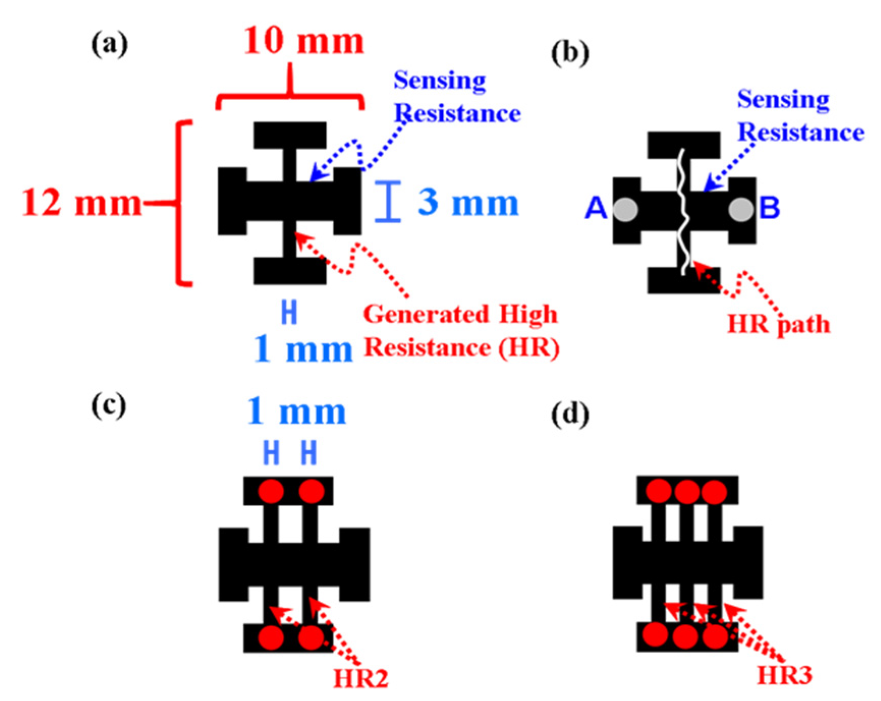
Figure 1. (a) Inkjet-printed +-shape piezoresistive (PR) strain sensor pattern. (b) The +-shape pattern constructed from two shapes of horizontal and vertical I. The horizontal and vertical I shapes were designed for the sensing PR resistance and the generation of the high resistive (HR) path, respectively. PR strain sensor pattern with (c) two and (d) three HR paths. The red circle denotes the measurement electrode for the generation of the HR paths.
Coatings 11 00051 g001
Figure 2. Optical transmittance of the +-shape flexible strain sensors measured with a UV-vis-NIR spectrophotometer.
Coatings 11 00051 g002
Figure 3. (a) Measurement setup of flexible PR strain sensors. (b) The relation between the applied strain (ε) and the arc r.
Coatings 11 00051 g003
Figure 4. (a) I-V characteristics of the +-shape flexible PR strain sensor measured with one full cycle of applying various å values from 0% to 0.33% and then releasing various ε values from 0.33% to 0%. The solid lines and symbols denote one full cycle of applying and releasing strain, respectively. (b) The relation between normalized resistance change (ΔR/R0) and applied ε with one full strain cycle corresponding to Figure 4a.
Coatings 11 00051 g004
Figure 5. The relation between ΔR/R0 and applied ε for 0, 1, 2, and 3 HR paths of the flexible PR strain sensors. For the PR strain sensor patterns, a pair of red circles denote the generation of one HR path. The gauge factor (GF) values of 43, 72, 97, and 165 extracted from the slope of the solid lines represent 0, 1, 2, and 3 HR paths, respectively. Exp._0, Exp._1, Exp._2, and Exp._3 denote the experimental data of 0, 1, 2, and 3 HR paths, respectively.
Coatings 11 00051 g005
Figure 6. (a) Linear and (b) log-linear I-V characteristics of three generated HR paths for the flexible PR strain sensor.
Coatings 11 00051 g006
Figure 7. Plot of GF dependence on the initial resistance R0 for 0, 1, 2, and 3 HR paths. The fitting line represents an exponential form to meet the experimental GF values.
Coatings 11 00051 g007
Figure 8. Plots of ln(RS/R0) dependence on the applied ε for 0, 1, 2, and 3 HR paths of the flexible PR strain sensors. The solid lines represent a fitting line to our experimental results with two parameters of γ and the initial tunneling distance (d0) in Equation (6). The γ·d0 of 41, 64, 87, and 138 can be found for 0, 1, 2, and 3 HR paths, respectively.
Coatings 11 00051 g008
Publisher’s Note: MDPI stays neutral with regard to jurisdictional claims in published maps and institutional affiliations.