Article

Experimental and Numerical Investigation of Light-Wood-Framed Shear Walls Strengthened with Parallel Strand Bamboo Panels

Department of Forestry Engineering, School of Civil Engineering, Northeast Forestry University, Harbin 150040, China
*
Author to whom correspondence should be addressed.
Coatings 2021, 11(12), 1447; https://doi.org/10.3390/coatings11121447
Submission received: 30 October 2021 / Revised: 16 November 2021 / Accepted: 23 November 2021 / Published: 25 November 2021

Abstract

:
This paper describes experimental and numerical investigations on a new type of strengthened light-wood-framed (LWF) shear wall (SW) that has parallel strand bamboo (PSB) panels at each end. The experiments are divided into two parts: (1) monotonic loading tests of panel-to-frame joints representing different positions along the wall; (2) monotonic loading tests of a group of traditional full-scale SWs and two groups of strengthened walls with nailed or screwed PSB panels. The failure modes, load–displacement curves, ultimate bearing capacity, elastic stiffness, and dissipation are analyzed, and the mechanical properties of panel-to-frame joints and the lateral performance of SWs are discussed. Moreover, nonlinear finite-element analysis shows that the numerical results are in good agreement with the test results. Our findings suggest that using LWF SWs strengthened with nailed PSB panels effectively improves the failure mode and the ductility, stiffness, and dissipation of traditional walls. Using sheathing screws on the PSB panels increases the lateral bearing capacity and the dissipation of the walls, but decreases their ductility ratio. Setting end PSB panels improves the overturning resistance capacity by restricting the uplift of studs. The LWF SWs strengthened with end PSB panels are found to meet the design requirements and reduce construction costs.

1. Introduction

Wood is a combustible material, which restricts its application in structures. Actually, wood structures are better able to withstand fire than steel structures [1,2]. Moreover, in recent years, the fire retardant and thermal insulation properties of wood have been extensively studied in order to make wood structures free from fire and temperature restrictions, including investigations of wood modification and flame retardant additives [3,4]. These effective measures have led to a wider use of wood structures [5,6]. Light-wood-framed (LWF) structures offer excellent ductility and good seismic performance, and are widely used around the world [7,8,9]. In the Chinese code for the design of timber structures, civil buildings with no more than three floors can be constructed using LWF assemblies [10]. However, developments in technology and materials mean that LWF structures are no longer limited to low-rise buildings, and taller constructions can achieve the necessary performance. The main members for bearing lateral loads are LWF shear walls (SWs) [11,12]. Therefore, multistory LWF structures require SWs that can bear higher lateral loads.
Generally, an LWF SW comprises framing members, sheathing panels, and fasteners. SWs with traditional sheathing panels (e.g., oriented-strand board (OSB) panels) have been examined numerically in previous studies [13,14,15,16]. These research studies showed that traditional LWF SWs fail because of joint failures between the framing members and sheathing panels near the bottom corners. The failure mode of a traditional SW is shown in Figure 1.
Recently, there have been several studies on the use of bamboo in LWF construction, and the results indicate that bamboo-based materials can be used as construction elements [17,18,19]. Xiao et al. [20] investigated the performance of LWF SWs sheathed with thick strip-ply-bamboo panels, and considered two types of sheathing nails. SWs with sizes of 1.22 m × 2.44 m and 2.44 m × 2.44 m were tested under lateral loading, and it was found that the damage patterns were similar to those of traditional LWF SWs; the bearing capacity and deformation performance were also similar to those of traditional SWs. In addition, Varela et al. [19] investigated the performance of LWF SWs sheathed with glued laminated Guadua bamboo (GLG) panels with different aspect ratios and sheathing nail spacings; lateral performance parameters such as the ultimate bearing capacity (UBC), secant shear modulus, and ductility ratio were obtained from tests, and the results showed that the GLG panels had a positive effect on the UBC and failure mode compared with traditional SWs. The aforementioned research shows that the types of sheathing panels and fasteners have a significant influence on the load-bearing capacity of LWF SWs, and their lateral performance can be improved by using high-strength sheathing panels [20,21]. In most cases, a bamboo-based composite material such as parallel strand bamboo (PSB) would be a good choice [22,23].
The capacity to resist overturning under a lateral force is a crucial factor for shear transfer in LWF SWs [24,25,26,27]. One effective way to increase the overturning capacity is to set a vertical load [28,29,30]. Johnston et al. [28] investigated how a vertical load affected the lateral performance of LWF SWs with and without hold-down; they tested 21 traditional 2.44 m × 2.44 m walls under no vertical load and under vertical loads of 6, 12, and 25 kN/m, and found that the lateral stiffness and energy dissipation capacity of the vertically loaded walls were better than those of the unloaded wall. Therefore, based on the aforementioned research, there is a positive correlation between the overturning resistance capacity and the lateral performance of LWF SWs.
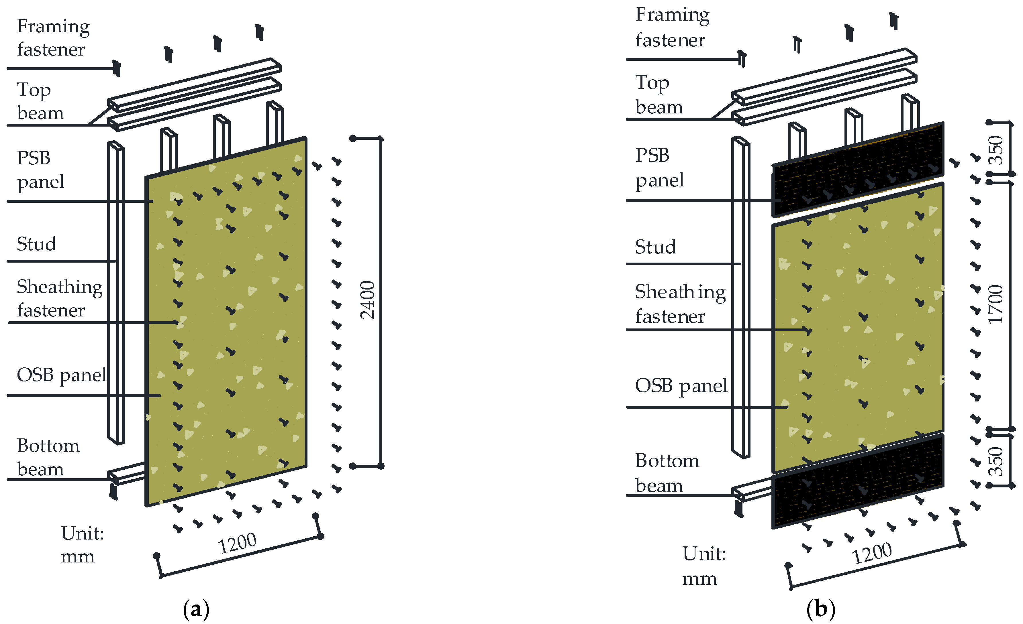
The traditional SWs of most LWF buildings are fully sheathed with OSB panels, which limit the lateral resistance of such walls. Based on the failure mode and lateral performance of pre-existing LWF SWs sheathed with high-strength panels, the damage is concentrated at the ends of the wall, which means that the mechanical properties of the sheathing panel in the middle of the wall are under-used. Therefore, a new type of LWF SW strengthened with PSB panels at both ends is discussed in this paper, with the aim being to increase the lateral performance of traditional SWs while using less high-strength sheathing material in the walls. The construction method for this new type of SW is similar to that of a traditional wall: a 1.70-m-high OSB sheathing panel supplemented by 0.35-m-high PSB panels at each end. The construction method for the new type of LWF SW is shown in Figure 2.
This paper describes experimental and numerical investigations of LWF SWs strengthened with PSB panels. Various factors affecting the lateral performance of the SWs are studied, including (i) the setting of the end PSB panels, (ii) the type of sheathing fasteners used on the PSB panels, and (iii) the vertical loads on the SWs. First, joints representing different positions along the wall are analyzed under monotonic loading. Panel-to-frame joints with PSB panels are tested to assess how the sheathing type and fastener type influence the lateral resistance capacity of the joints; the test data are then used as the basic data for finite-element analysis (FEA). The test walls, comprising a group of traditional LWF SWs and two groups of walls strengthened with PSB panels, are examined under monotonic lateral loading, and we discuss the enhancement of the lateral performance due to the PSB panels at the ends. We also study the failure mode and lateral behavior parameters of this new type of wall with different sheathing fasteners used on the PSB panels. We then develop FEA models of the strengthened walls for further parametric studies. We discuss how (i) the capacity of the panel-to-frame joints and (ii) the uniform vertical loads at the tops of the walls affect the lateral performance of the walls.

2. Materials and Methods

2.1. Experimental Program

The new type of SW was subjected to two types of tests: (i) those focused on the joints in the SW, with two types of joint used to represent different positions along the SW, namely stud-beam joints and panel-to-stud joints; and (ii) those focused on full-scale wall units.

2.1.1. Material Properties

The materials and specifications used in the elements of the specimens were selected according to GB50005-2017 [10,31], and are given in Table 1. PSB and OSB are well known bio-composites made from natural bamboo and wood, respectively. In this study, the PSB panels were made of Neosinocalamus affinis, and the OSB panels were made of Aspen.
The moisture content and mechanical properties of the materials used to construct the test specimens are listed in Table 2.
The moisture content for the materials was measured according to the relevant Chinese code [32]. The mechanical properties of the framing and sheathing materials were determined according to several Chinese codes [33,34,35,36,37,38]. The bending strength of the sheathing fasteners was determined and calculated according to ASTM F1575-03 [39]. Therefore, the bending yield moment of the smooth nails was 2232.66 N·mm, and that of the screws was 4909.67 N·mm.

2.1.2. Test Specimens

We fabricated 48 joints in the LWF walls and tested them to failure to obtain their UBC and elastic stiffness. We then used the test data in the subsequent FEA. Details of the joints are shown in Figure 3.
The panel-to-frame joints were divided into two groups, traditional (T) and new (N), depending on the type of sheathing panel. Group T consisted of nailed joints with OSB panels, which is the form commonly used in traditional LWF SWs; group N comprised joints with PSB panels, as used in the new type of LWF SW. The joints with the PSB panels were further divided into four groups according to the types of joint and sheathing fastener. Each joint in group N had a predrilled hole with a diameter of 2.5 mm. The parameter values of the test joints are given in Table 3.
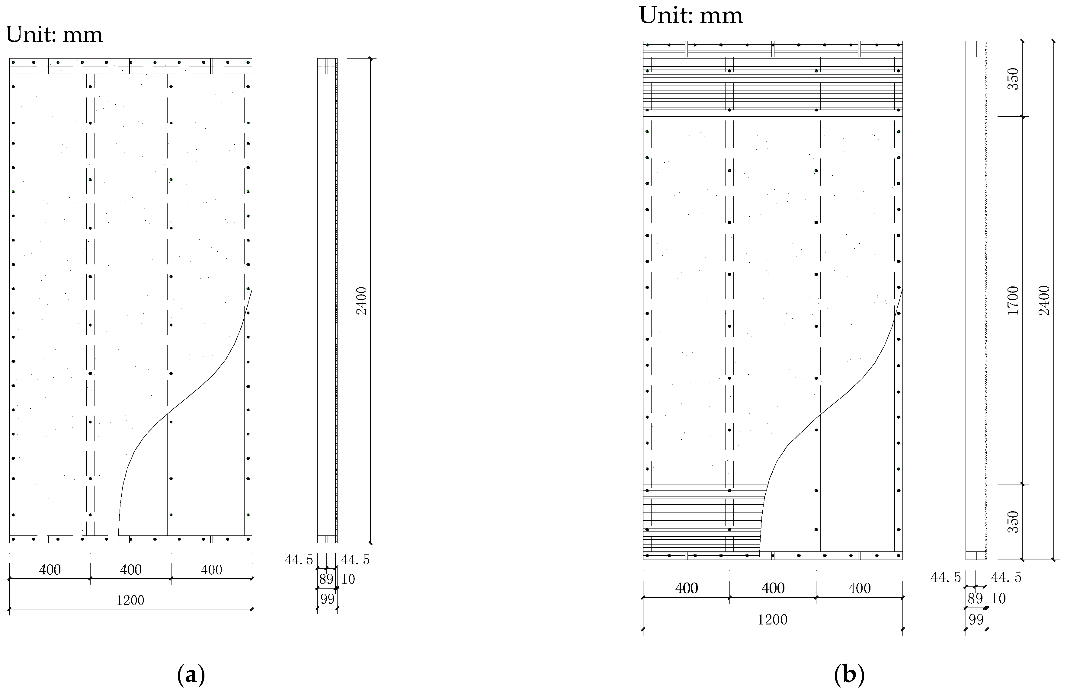
We tested six LWF SWs to determine their monotonic lateral performance. The wall elements were tested in three groups. Test group I was designed to obtain basic information about traditional walls with nailed OSB panels; in this case, the size of the OSB panel was 1.2 m × 2.4 m. In test group II, PSB sheathing panels were applied to both ends of a wall to study the effect of setting those end panels; in this case, the size of the OSB panel was 1.2 m × 1.7 m and the size of each PSB panel was 1.2 m × 0.35 m. In test group III, screws were used on the PSB panels at both ends of a wall to study the effect of the type of sheathing fastener used on the PSB panels. The parameter values of the test walls are presented in Table 4.
The wall dimensions were 1.2 m × 2.4 m. The studs and beams were connected with framing fasteners, and the frame covering was attached at one side of the frame. The nails used on the OSB panel were spaced at 150-mm intervals along the outside edges of each panel, or at 300 mm along the interior studs. The PSB panels were connected to the framing members with either smooth nails or screws. The sheathing fasteners used on the PSB panels were spaced at 150-mm intervals along the outside edges of the PSB panels and the interior studs. The details of the walls are shown in Figure 4.

2.1.3. Test Setup, Instrumentation, and Test Procedure

The steel jigs used for the joints are shown in Figure 5. Monotonic tests of the joints were conducted under deformation control with a loading rate of 2.54 mm/min in accordance with ASTM D1761 [40].
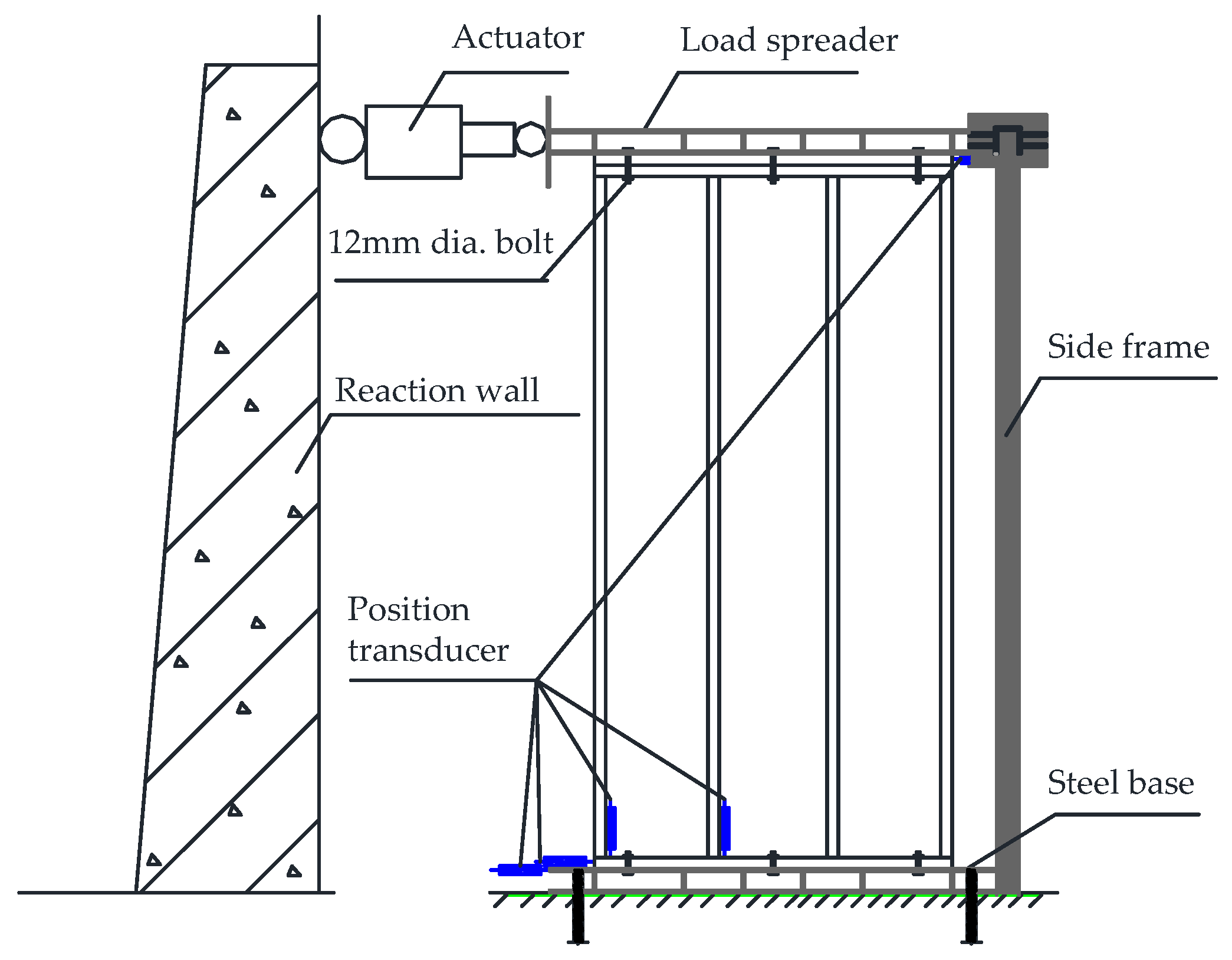
The experimental setup and locations of the transducers for the test walls are shown in Figure 6. The side frame was set as a lateral brace to ensure the in-plane deformation of the SWs. The displacement-controlled loading mechanism followed ASTM E564 [41]. The horizontal loading rate was 7.5 mm/min.

2.1.4. Load–Displacement Relationships and Lateral Performance Parameters

Based on the load–displacement curves, we could calculate the lateral performance parameters according to ASTM E2126-09 [42]. The UBC Pmax and the displacement at failure load Δfailure were obtained from the tests. The failure load Pfailure was the load degraded to a value equal to 0.8Pmax. The dissipation A was the area under the load–displacement curve. The ductility ratio was μ = Δfailureyield, where Δyield was the displacement at the yield load Pyield, which was calculated as
P yield = ( Δ failure Δ failure 2 2 A K 0.4 P max ) K 0.4 P max ,
The load–displacement curve of the joints at the initial stage of loading was greatly affected by the loading direction. Thus, we defined the elastic stiffness of the joints as
K e = 0.4 P max 0.2 P max Δ 0.4 P max Δ 0.2 P max ,
The initial stiffness [19,43,44,45] of SWs was K = Pii, where Δi was taken as 1/250 of the wall height H and Pi was the corresponding load.

2.2. Nonlinear Finite-Element Analysis

2.2.1. Nonlinear Finite-Element Analysis Model

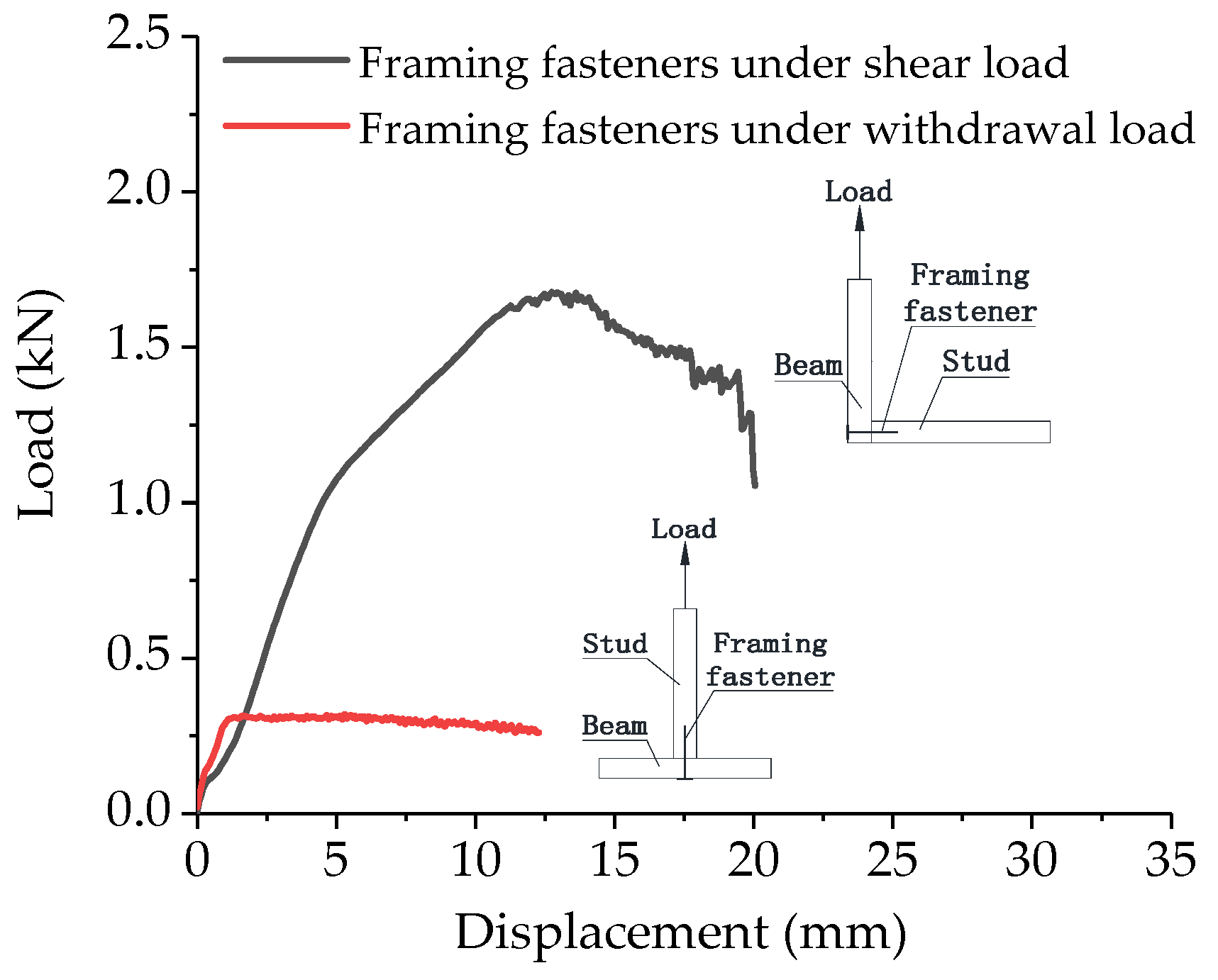
We conducted nonlinear FEA to further investigate how setting the end PSB panels and the type of sheathing fasteners used in them affect the lateral performance of the LWF SWs under vertical loading. We established models of LWF SWs in the finite-element program 6.12 ABAQUS [46]; simplified two-dimensional models were used to simulate the lateral performance of the SWs simply and efficiently. The sizes of the FEA models were the same as those of the experimental specimens. The material parameters of the anisotropic components were defined according to Table 4. The top beams, bottom beams, and studs were subjected to axial loads and bending moments simultaneously. Therefore, we used B21 elements for the framing members and CPS4R elements for the sheathing panels. We used nonlinear spring units for the joints of the walls. The beam-to-stud joints were also tested in the same way as the sheathing-to-framing joint tests; the load–displacement curve of beam-to-stud joints is shown in Figure 7. The parameters of the constitutive model of the nonlinear spring units were obtained from the test results [47,48,49,50,51].
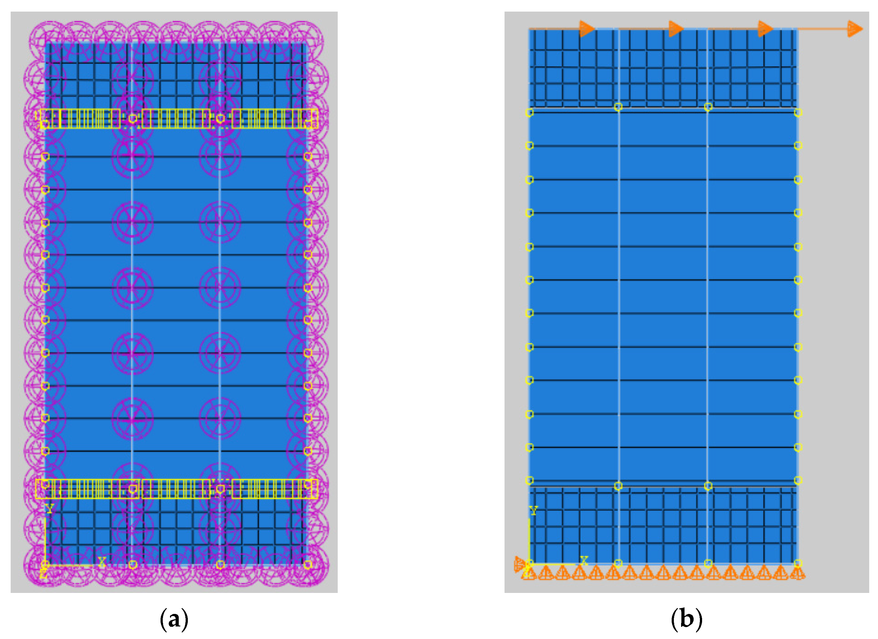
A specimen was considered to have failed when the load carrying capacity degraded to 80% of its maximum value [42]. In the single-spring model, because the displacement trajectory of a sheathing-to-framing joint is primarily unidirectional during monotonic loading, the total displacement of the joint may be estimated as the resultant displacement [49,50,51]. However, because of the angle between the joint deformations in the wall and joint tests, the parameters of the nonlinear spring must be calibrated iteratively [49]. The P–Δ effect was not accounted for in the analysis. The contact interactions were set between the OSB panel and the PSB panels. The tangential behavior and normal behavior were defined as contact properties. The penalty was selected in the friction formulation of tangential behavior. The boundary condition of the bottom beam was modeled by restraining the displacement in the x and y directions at the initial analysis step. The lateral displacement was set on the top beam, consistent with the experiment. The hard contact was selected based on the pressure–overclosure relationship of the normal behavior. The boundary condition and setting of the spring and contact are shown in Figure 8. In order to determine the effect of the finite element mesh discretization pattern on the accuracy of the results, FEA models with meshing sizes of 100, 50, and 25 mm, respectively, were implemented.

2.2.2. Parametric Studies

Based on the verified model of a PSB-strengthened LWF SW, 12 different configurations were investigated further, including walls with uniform vertical loads of 6, 12, 18, and 24 kN/m. The parameter values for these wall models are given in Table 5.

2.3. Comparison with Design Codes

According to Eurocode 5 (EC5) [52], the characteristic load-bearing capacity of the test joints was calculated as
F c = min { f h 1 , k t 1 d e a f h 2 , k t 2 d e b f h 1 , k t 1 d e 1 + β h [ β h + 2 β h 2 [ 1 + t 2 t 1 + ( t 2 t 1 ) 2 ] + β h 3 ( t 2 t 1 ) 2 β h ( 1 + t 2 t 1 ) ] + F ax , Rk 4 c 1.05 f h 1 , k t 1 d e 2 + β h [ 2 β h ( 1 + β h ) + 4 β h ( 2 + β h ) M y , Rk f h 1 , k t 1 2 d e β h ] + F ax , Rk 4 d 1.05 f h 1 , k t 2 d e 2 + 2 β h [ 2 β h 2 ( 1 + β h ) + 4 β h ( 1 + 2 β h ) M y , Rk f h 1 , k t 2 2 d e β h ] + F ax , Rk 4 e 1.15 2 β h 1 + β h M y , Rk f h 1 , k d e + F ax , Rk 4 f ,
where t1 is the thickness of the sheathing panel, fhi,k is the characteristic embedding strength in timber member i, de is the effective diameter of the fasteners, My,Rk is the characteristic fastener yield moment, βh is the ratio of embedding strengths (βh = fh2,k/fh1,k), and Fax,Rk is the characteristic axial withdrawal capacity of the fasteners.
f hs = 0.082 ( 1 0.01 d e ) ρ k ,
where ρk (=420 kg/m3) is the density of the timber.
From EC5 [52], the characteristic embedding strength for the PSB and OSB sheathing was calculated as
f hp , PSB = 30 d e 0.3 t 0.6 ,
f hp , OSB = 65 d e 0.7 t 0.1 ,
where t is the thickness of the sheathing panel.
F ax , Rnk = { f ax , k d t pen f ax , k d t + f head , k d h 2 ,
f ax , n = 20 × 10 6 ρ k 2 ,
f head , n = 70 × 10 6 ρ k 2 ,
where fax,n is the characteristic pointside withdrawal strength, fhead,n is the characteristic head pull-through strength, d is the nail diameter, tpen is the pointside penetration length or the length of the threaded part in the pointside member, t is the panel thickness, and dh is the nail head diameter.
According to EC5 [52], the characteristic withdrawal capacity for the screws was calculated as
F ax , Rsk = f ax , k d e l ef k d ,
f ax , k = 0.52 d e 0.5 l ef 0.1 ρ k 0.8 ,
k d = m i n { d e 8 1 ,
where fax,k is the characteristic withdrawal strength perpendicular to the grain, de is the effective screw diameter, and lef is the penetration length of the threaded part.
The design strength was calculated using EC5 [52] as
F i , d = F i , k γ M ,
where Fi,k is the characteristic strength and γM (=1.3) is the partial factor.
According to Chinese code (GB50005) [10], the characteristic load-bearing capacity of the test joints was calculated as
F c = min { R e t 2 d f es   ( R e R t < 1.0 ) a R e t 2 d f es   ( R e R t = 1.0 ) b f h 1 , k t 1 d e 1 + β h [ β h + 2 β h 2 [ 1 + t 2 t 1 + ( t 2 t 1 ) 2 ] + β h 3 ( t 2 t 1 ) 2 β h ( 1 + t 2 t 1 ) ] c f h 1 , k d e β h t 2 1 + 2 β h [ 2 ( 1 + β h ) + 1.647 β h ( 1 + 2 β h ) k e d e 2 f yk 3 β h f h 1 , k t 2 2 1 ] d f h 1 , k t 1 d e β h 2 + β h [ 2 ( 1 + β h ) β h + 1.647 β h ( 1 + 2 β h ) k e d e 2 f yk 3 β h f h 1 , k t 1 2 1 ] e f h 1 , k d e 2 1.647 β h k e f yk 3 ( 1 + β h ) f h 1 , k f ,
where fyk is the characteristic fastener yield strength.
The design strength was calculated using GB50005 [52] as
F i , d = F i , k γ M ,
where Fi,k is the characteristic strength and γi is the partial factor for different failure modes (γa = 4.38 for fastener using screw; γa = 3.42 for fastener using nail; γb = 3.63 for fastener using screw; γb = 2.83 for fastener using nail; γc = 2.22; γd = 1.88).
The design lateral bearing capacity calculated using EC5 [52], in which design method B is used for the SW without hold-down, was calculated as
F V = k s k d k q k n b F c s 0 ,
k q = 1 + ( 0.083 q 0.0008 q 2 ) ( 2.4 b ) 0 . 4 ,
where Fc is the lateral design capacity of an individual fastener, b is the wall length, s0 is the basic fastener spacing (s0 = 9.7 d/ρk), ks is the fastener spacing factor (ks = 1/(0.86 s/s0 + 0.57), kd is the dimension factor for the wall (kd = b/h for b/h < 1), kq is the uniformly distributed load factor for the wall, kn is the sheathing material factor (kn = 1 for sheathing on one side), and q is the equivalent uniformly distributed vertical load acting on the wall.
The design lateral bearing capacity, calculated using GB50005 [10], was calculated as
F V = k 1 k 2 k 3 b f vd ,
where fvd is the design value of shear strength of SWs, b is the wall length, k1 is the moisture content factor (k1 = 1.0 for moisture content lower than 16%), k2 is the framing material factor (k2 = 0.8 for framing using SPF), k3 is the strength factor for the wall without bracing (k3 = 0.6).

3. Results

3.1. Experimental Results

3.1.1. Failure Modes

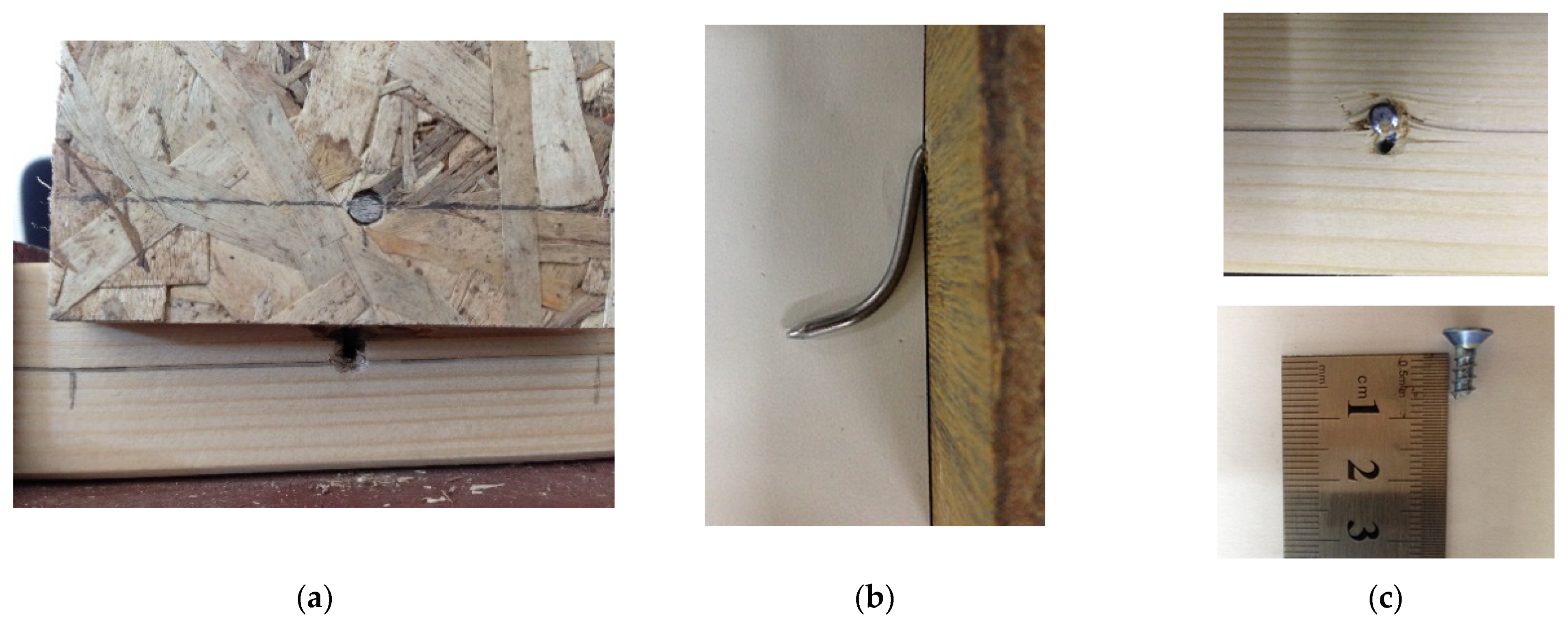
The ultimate failure modes of the panel-to-frame joints are shown in Figure 9. In the tests, the main ultimate failure modes of the nailed panel-to-frame joints with the OSB panel and PSB panels were nail yielding followed by the withdrawal of nails from the framing member. Nails embedded into the sheathing panel were found in joints with the OSB panels, but not in those with the PSB panels. The failure mode of the screwed joints was brittle failure of the screws.
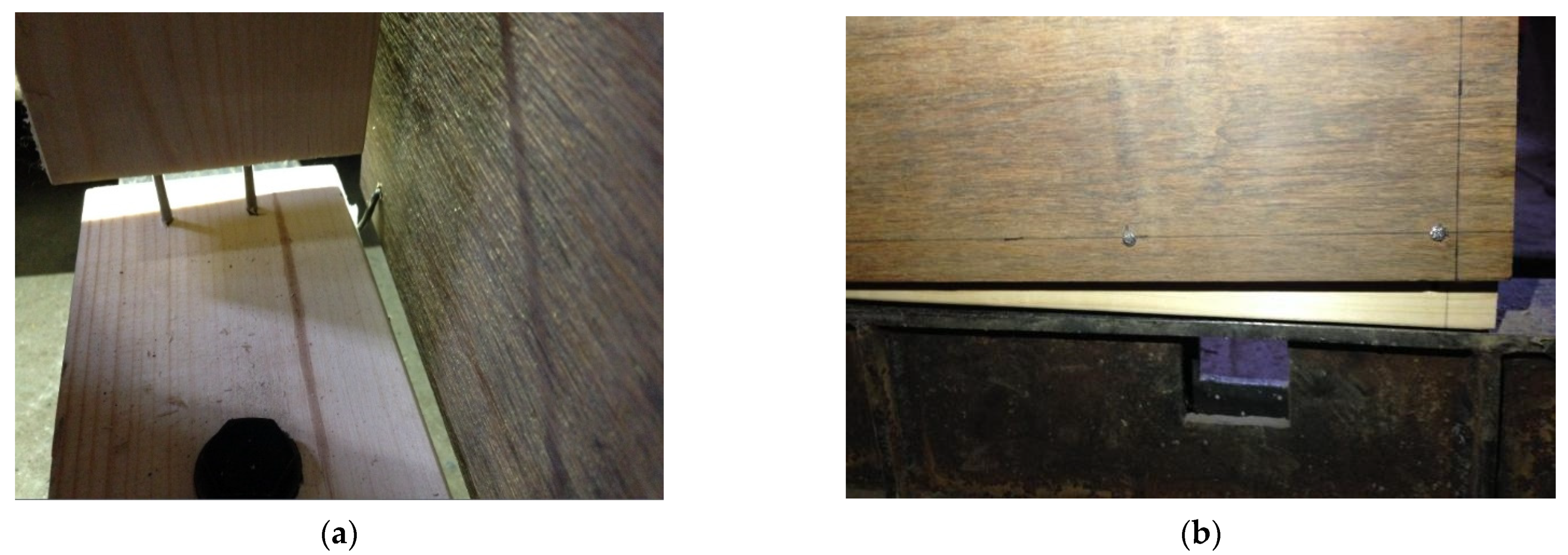
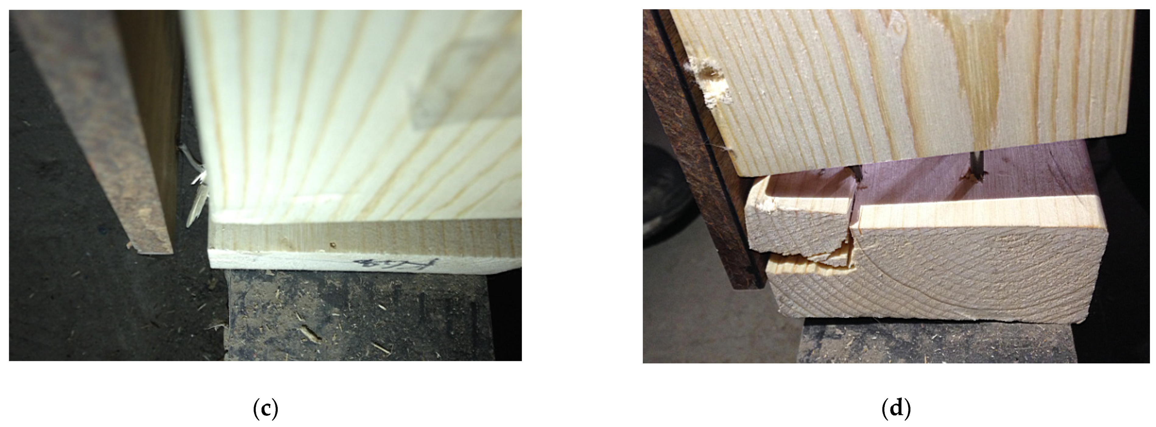
The ultimate failure modes of traditional SWs are shown in Figure 1. In the traditional SW specimens, the sheathing nails had pulled out of the bottom beam, and their heads had become embedded in the OSB panel, splitting its edges. The ultimate failure modes of the strengthened walls are shown in Figure 10. The main deformation patterns of the SWs strengthened with PSB panels look basically the same as those of the traditional SWs, but no embedding of nails or splitting of the PSB panels had occurred in the SWs strengthened with PSB panels. In addition, splitting of the bottom beam had occurred in the SWs strengthened using PSB panels with screws.
Compared with the failure modes obtained from the panel-to-frame joint tests, the failure modes of the SWs at the joints were similar. There was some difference between the panel-to-frame screwed joints with the PSB panels and the screwed PSB-panel-strengthened walls, because the effect of multiple screws on the framing material was not accounted for in the joint tests. The failure modes of the specimens are summarized in Table 6.

3.1.2. Load–Displacement Relationships and Lateral Performance Parameters

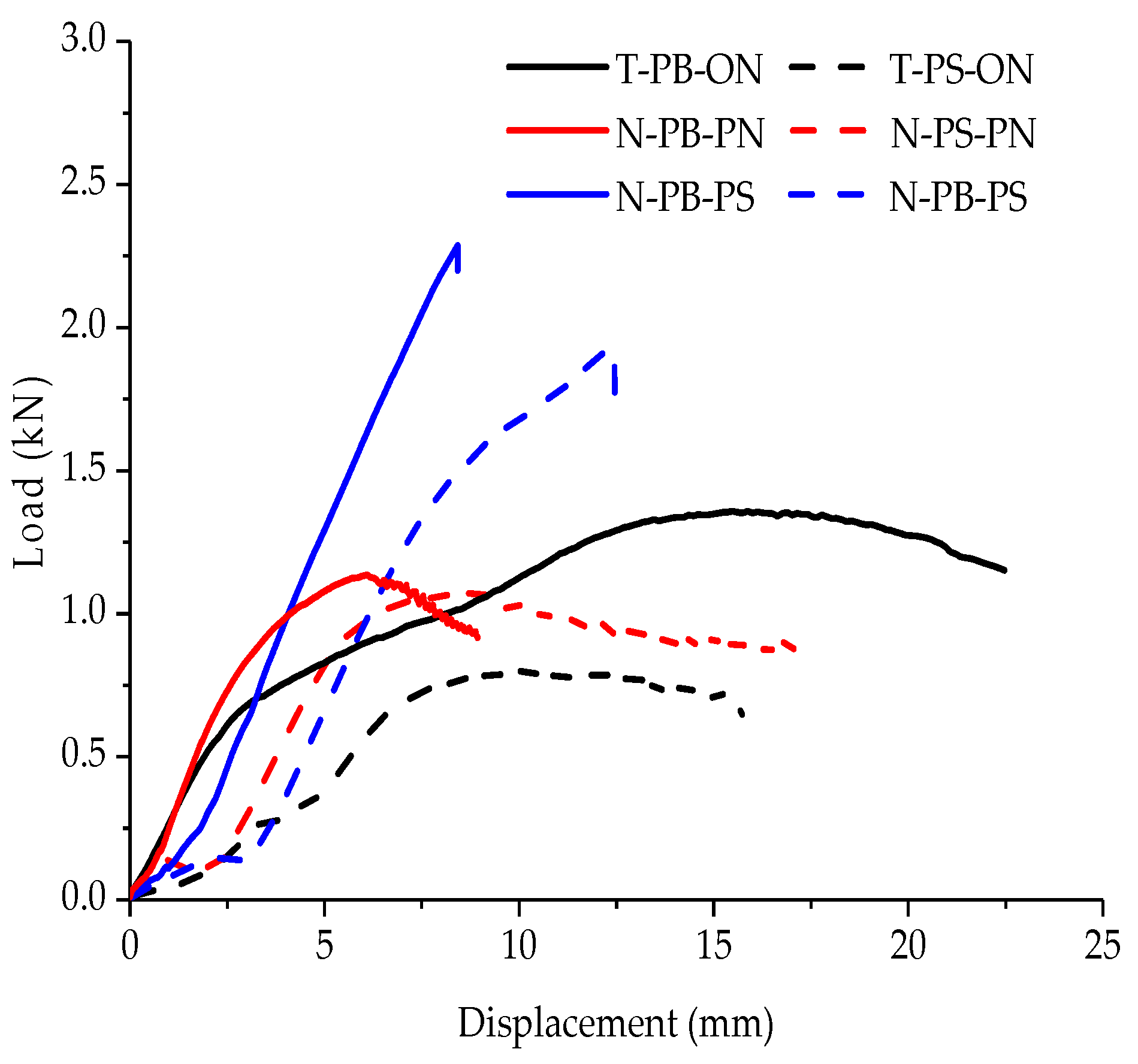
The average load–displacement curves for the test joints are compared in Figure 11. As with traditional joints, the load–displacement relationship of the nailed panel-to-frame joints with the PSB panels was nonlinear; in contrast, the load–displacement relationship of the screwed joints with the PSB panels was linear. The load–displacement curves of the joints show that the load of the panel-to-stud joints rose slowly in the early phase of loading, with the load–displacement curves of the panel-to-stud joints lagging behind those of the panel-to-beam joints; this was due to the fasteners slipping along the direction of the wood grain. When the loading direction was parallel to the direction of the wood grain, the wood-grain bonding was weak, and the concentrated force could easily split the wood fibers. For joints with screws, the load–displacement curve rose slowly in the early phase of loading. This was because the contact between the screw and the component to which the screw was attached was flexible, and thus, the threads of the screw were extruded and compacted with the surrounding fibers at the beginning of loading.
The parameter values for the mechanical properties of different joints are presented in Table 7. As can be seen, the sheathing panel types and the sheathing fastener types affected the mechanical properties of the panel-to-stud joints and panel-to-beam joints differently. This was because the angle between the wood grain and the loading direction affected the deformation and force characteristics of the fasteners in the joints. The UBC, stiffness, ductility, and dissipation of the panel-to-stud joints with the OSB panel were lower than those of the same joints with a PSB panel; this was because the rigid PSB panel limited the deformation of the fasteners within it, resulting in the formation of two hinges in the fastener. However, in the panel-to-beam joints, replacing part of the OSB panel with PSB panels reduced the UBC of the joints. The lateral bearing capacity of the joints was determined by the bending strength of the fasteners, the embedding strength of the sheathing and framing material, and the withdrawal strength of the fasteners. Because the diameter of the pre-drilled holes in the sheathing and framing members was the same as that of the nails, the friction between the nails and the framing members was reduced, which made it easier to withdraw the nails. Replacing the nails with screws when using PSB panels further enhanced the UBC of the joints. The primary reason for this effect was that the diameter of the predrilled holes was less than that of the screws, and thus, the bending capacity and withdrawal capacity of the screws, which were significantly higher than those of the nails, were used more efficiently. In addition, the elastic stiffness of the joints with the PSB panels was higher than that of traditional joints, because the mechanical properties of PSB panels were better than those of OSB panels. Because of the poor ductility of screws, joints using screws also have poor ductility, although they have better load-bearing capacity and stiffness.
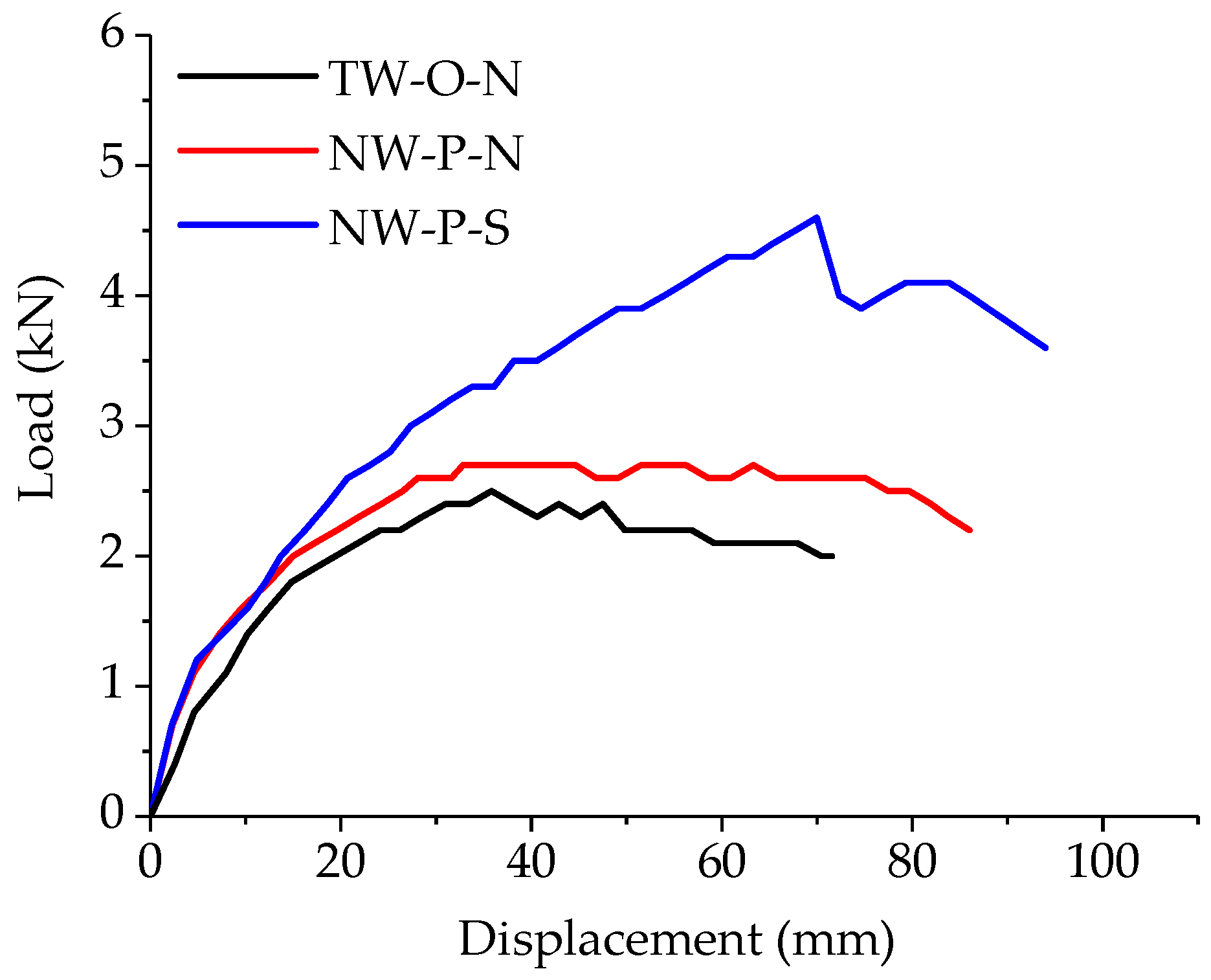
The average load–displacement curves for the test SWs are compared in Figure 12. The parameter values for the lateral performance of different SWs are presented in Table 8.
The main variables considered when studying the SWs were (i) the setting of the end PSB panels and (ii) the types of sheathing fastener used on the PSB panels. The results show that these variables had a significant effect on the general load–displacement relationships of the test specimens. Setting the PSB panels and using screws in them increased the load–displacement performance of the traditional SWs. He et al. showed experimentally that using a smaller sheathing panel in the wall results in less strength and stiffness than using a larger sheathing panel [45]. The PSB-strengthened LWF SW was equivalent to dividing one large sheathing panel into three, and the deformation of the sheathing panel changed from rotation of the entire sheathing panel to three panels with varying degrees of rotation. The deformation of the LWF SW is shown in Figure 13. The UBC of the test walls was much lower than in existing studies, which reported UBCs of ~10–20 kN for 1.22-m-wide walls [26,27,28,29]. This discrepancy is due to the hold-down setting in the previous studies [26,27,28,29]. In contrast, in the present study, no hold-down was provided in the test walls so that the effect of setting PSB panels at the ends on the restraining capacity of the wood frame could be clearly observed.
As can be seen in Figure 12 and Table 8, setting the end PSB panels without changing the sheathing fasteners increased the UBC by 10%, the stiffness by 21%, the ductility by 83%, and the dissipation by 43%. Because the UBC of the walls depended mainly on the bending resistance of the sheathing fasteners, the increase in the UBC of the wall was small when the same sheathing nails were used and the PSB panels were set only at the ends. However, because the material properties of the PSB panels were considerably better than those of OSB panels, the PSB panels produced a better skin effect when the wall was loaded. This resulted in a substantial increase in the ductility and dissipation of the nailed PSB-strengthened SWs. For the walls using screws on the end PSB panels, the UBC and dissipation of the walls increased by 67% and 19%, respectively, compared with PSB-strengthened SWs with nails used on the PSB panels. Using screws in the end PSB panels greatly improved the UBC compared with using nails. This was due to the high bending strength of the screws and the ability to exploit that bending strength in combination with the PSB panels. However, the ductility of the walls was 60% lower than that of nailed PSB-strengthened walls and 26% lower than that of traditional LWF SWs. The poor ductility of the PSB–screw joints was apparent in the joint tests, but the joints still had a certain ductility when applied to the wall.
When comparing the performance of the joints with that of the corresponding SWs, it is clear that there were scaling effects between the joints and the walls. First, there was a scaling effect on the failure mode. The OSB–nail joints did not exhibit any OSB–panel splitting, but the OSB panel split in the traditional LWF SW. The main failure mode of PSB–screw joints was brittle failure of the screws, but the bottom beams split in the corresponding walls. The second scaling effect concerned the lateral performance. The lateral performance of the panel-to-beam joints was the main determinant of the lateral UBC of the walls [12,15]. The performance of panel-to-beam joints is a major consideration when designing the lateral bearing capacity of walls. Therefore, the lateral performance of panel-to-beam joints should be compared with the overall lateral resistance of the wall. The effects of these variables on the stiffness and ductility of the wall were consistent with those of the corresponding joints. However, there were small deviations in the UBC and dissipation.
Therefore, because the lateral performance of the traditional SWs was improved, we reason that an LWF SW strengthened with PSB panels is feasible and workable. The primary reason for this effect was that the PSB panels showed excellent mechanical properties that brought all the materials fully into play. In addition, the bending capacity and withdrawal capacity of the screws were significantly higher than those of nails.

3.2. FEA Results

3.2.1. FEA Model Verification

Figure 14 compares the experimentally and numerically obtained partial deformations of several walls. Since there was no bracing in the wall, the gap between the OSB panel and PSB panel became larger because the rotation angles of the OSB panel and the PSB panel were different when the wall was in failure mode. Furthermore, there was a horizontal misalignment displacement between the OSB panel and the PSB panel. The deformation of the joint at the bottom corner of the wall was mainly expressed by the stud uplift and the sheathing panel leaving the bottom beam. The vertical displacement of the studs was larger than the vertical displacement of the sheathing panels. As can be seen, the FEA results agreed well with the test results.
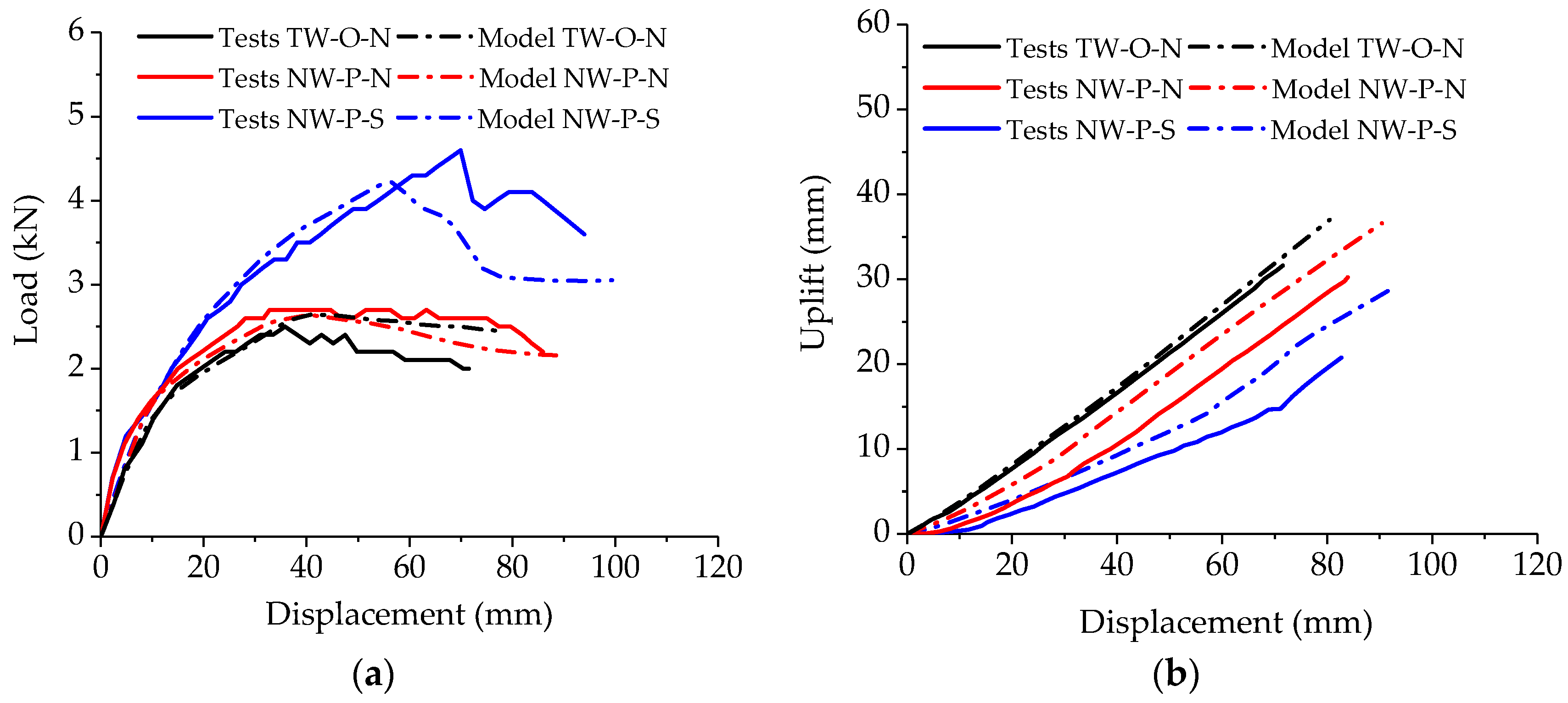
Figure 15 compares the experimentally and numerically obtained load–displacement curves and uplift–displacement curves of several walls. During the subsequent stages of loading, the deviation between the FEA and experimental results increased, mainly due to component manufacturing, test errors, and errors in the joint test parameters. Among these factors, the panel-to-frame joint test data had the greatest impact. Because the individual test specimens in the joint tests represented only a component force of the fastener in the wall, the fastener group effect and the internal force redistribution in the walls were neglected.
During the subsequent stages of loading, the deviation between the FEA and experimental results increased, mainly due to component manufacturing, test errors, and errors in the joint test parameters. Among these factors, the panel-to-frame joint test data had the greatest impact. Because the individual test specimens in the joint tests represented only a component force of the fastener in the wall, the fastener group effect and the internal force redistribution in the walls were neglected.
The FEA results show that (i) the ultimate load of the traditional SW was overestimated and (ii) the ultimate loads of the SWs strengthened with PSB panels were underestimated. This was because the joint tests considered only a single loading direction without accounting for panel rotation. The sheathing panel was also subject to rotation, and its bottom edge actually split because the FEA neglected the weaker performance of the OSB panel; the FEA also neglected the better skin effect of the PSB panels. However, comparing the uplift–displacement curves of the end stud of the TW-ON and the NW-PN showed that the stud uplift was effectively limited when the PSB panels were only set with nails. The Figure 15 also shows that the PSB panels resist rotation better than OSB panels. Using screws when setting the end PSB panels further limited the stud uplift.
As can be seen, the curves corresponded reasonably well in each case. Furthermore, we see that the error in the ultimate load between the FEA and experimental results was within 10%; therefore, the ultimate loads of the walls simulated through FEA were in good agreement with the test results. Although the uplift of the end stud differed between the FEA and experimental results, the influence and trends of the variables given by FEA were the same as in the experimental results. Consequently, the model developed herein accurately reflects the force conditions of LWF SWs strengthened with PSB panels.
The load–displacement curves obtained from FEA are shown in Figure 16. According to Figure 16, it can be seen that the finite element mesh discretization had little effect on the shape of the load–displacement curve of the model. The load–displacement curves obtained from the FEA with different meshing sizes were almost the same.
The results of the FEA with different meshing sizes are shown in Table 9. According to Table 9, it can be seen that the meshing size at the top and bottom of the wall affected the ultimate bearing capacity of the model within 1.8%. This was due to the assumption in the finite element analysis that the materials were all in the elastic range. The failure of the wall was caused by the nonlinear springs used to simulate the joints. In addition, for every doubling of the meshing size in the finite element model of PSB-reinforced light wood frame shear walls, the computing time increased by about 40%. Therefore, the meshing size of the model in the subsequent parametric analysis was 100 mm.

3.2.2. Parametric Studies

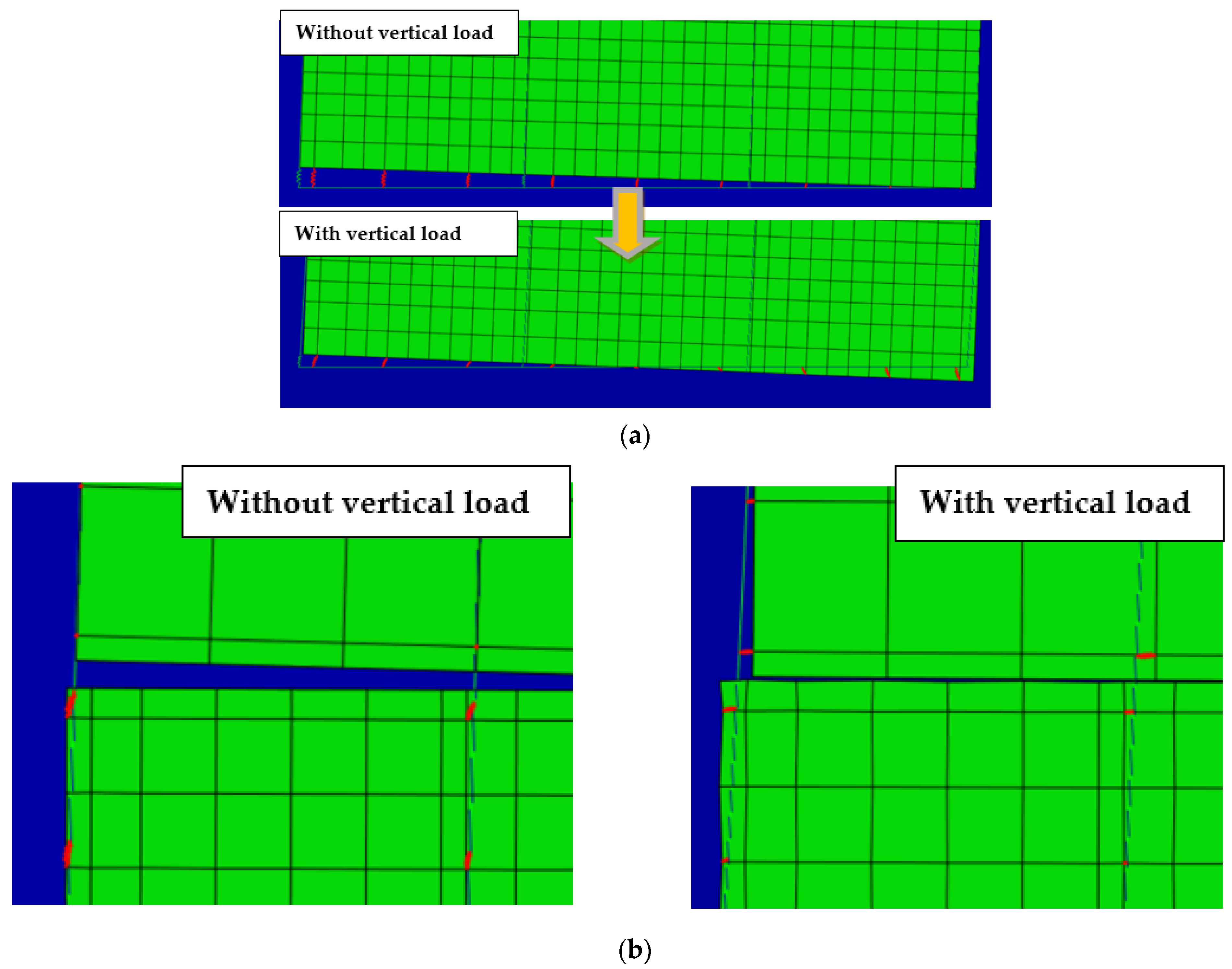
Based on the verified model of a PSB-strengthened LWF SW, 12 different configurations were investigated further, including walls with uniform vertical loads of 6, 12, 18, and 24 kN/m. Figure 17 shows the deformation of the SW joints under vertical loading. We now discuss how the vertical load affected the deformation of the wall through comparisons with an LWF SW with no vertical load. As can be seen, the center of rotation at the bottom of the sheathing panel moved closer to the center of the wall under the action of the vertical load. Moreover, the deformation of the sheathing-to-frame joints near the bottom of the wall changed from nearly parallel to the studs to an increased angle from the studs. Thus, the combined force of all the sheathing-to-frame joints began to act in the direction perpendicular to the actual loading direction.
Because the UBC in the FEA results reflects the force conditions of LWF SWs strengthened with PSB panels, we will further discuss the ultimate load of the LWF SW under different vertical loads. Figure 18 shows the UBC of the SW at the limit state according to the FEA results. According to Figure 18, the UBC of the SW was proportional to the vertical load. Additionally, with increasing vertical load, the extent of the increase in the UBC decreased. For a traditional LWF SW, its UBC with a vertical load of 24 kN/m was almost the same as that with a vertical load of 18 kN/m; this was consistent with the conclusions reached in previous studies [28]. In contrast, for a PSB-strengthened LWF SW, its UBC under a vertical load of 24 kN/m was still significantly higher than that under a vertical load of 18 kN/m. Furthermore, the increase in the UBC of the screws used in the PSB panels was slightly larger than that of the common smooth nails used in those panels. This was because, with increasing vertical load, the UBC of the wall depended more on the combined force performance of the panel-to-beam joints and the panel-to-stud joints than on the performance of the joints in a single loading direction. The joint test results show that the UBCs of the nailed panel-to-beam joints with the OSB panel were slightly better than those of the panel-to-beam joints with the PSB panels, but the nailed panel-to-stud joints with the OSB panel were significantly weaker than the nailed panel-to-stud joints with the PSB panels. The UBCs of the nailed panel-to-beam joints and the nailed panel-to-stud joints with PSB panels were similar. Therefore, the combined performance of the nailed joints with the PSB panels was better than that of the nailed joints with the OSB panel. In the case of sheathing fasteners with nails, the UBC of a wall with end PSB panels under vertical loading was slightly higher than that of a traditional wall under vertical loading. Similarly, for both panel-to-beam joints and panel-to-stud joints, the UBC of PSB–screw joints was significantly higher than that of PSB–nail joints. Therefore, the UBC of the PSB-strengthened SWs with screws was significantly higher than that of the PSB-strengthened SWs with nails. As was previously shown, after increasing the overturning resistance of SWs by vertical loading, replacing the ends of the OSB panel with PSB panels slightly increased the UBC of traditional SWs, and using screws in the PSB panels significantly improved the UBC of SWs with nails.

3.3. Comparison with Design Codes

3.3.1. Comparison of Bearing Capacity with Eurocode 5

The characteristic and design values of the elements in the joints were calculated according to EC5 [52], and the results are given in Table 10. The calculated data were used for subsequent reliability analysis. Compared with the UBC obtained from joint tests, the characteristic value of the bearing capacity for the joints calculated according to EC5 decreased by 46% for the OSB-nail joints and by 58% for the PSB-nail joints. This was because PSB panels offer a more reliable compression strength than OSB panels. The characteristic value of the bearing capacity of the PSB-screw joint was 50% of the UBC obtained from joint tests. This was due to the limitation of the withdrawal strength of screws in EC5 in order to guarantee the reliability of the design. By comparing the characteristic values of bearing capacity for each group of joints, it can be seen that the estimates for the joints using low-density sheathing panels and low-ductility sheathing fasteners were on the conservative side.
Comparing the corresponding load values of the walls calculated in EC5 with the UBC obtained from FEA shows that the trend for how the vertical load influences the load-bearing capacity of the walls obtained from FEA was consistent with the calculations based on EC5. Moreover, the coefficient kq shows that the effect of vertical loading on the UBC of the wall was nonlinear, which was consistent with the FEA results. These aspects further demonstrate the validity of the FEA results, as well as showing that the new type of wall is still suitable for the design methods in EC5. Figure 19 and Table 11 show that the design values of the UBC of traditional walls are much smaller than the FEA results; this proves that traditional LWF SW designs are safe. However, the design values of the new type of PSB-strengthened LWF SWs were closer to the FEA results. As indicated, the load capacity of the joints calculated according to EC5 was high and the design values were on the unsafe side. Therefore, the design values of the joints in SWs with PSB panels must be further studied and revised.

3.3.2. Comparison of Bearing Capacity with Chinese Code

Figure 20 compares the predicted shear strength of the walls with the design values of the bearing capacity of LWF SWs as specified in the Chinese code [10]. The shear-strength range specified in the Chinese code [10] is from 3.5 (for 9.5-mm-thick OSB panels with 2.84-mm-diameter nails and hold-down) to 6 kN/m (15.5-mm-thick OSB panels with 3.66-mm-diameter nails and hold-down). Therefore, the design value range calculated according to GB50005 for the traditional walls was from 3.36 to 5.76 kN, and the design value range calculated according to GB50005 of the walls strengthened with end PSB panels was from 2.02 to 3.46 kN. Moreover, the characteristic and design values of the LWF SWs were calculated according to the shear wall design procedure in EC5 [52] and the joint design procedure in GB50005 [10], and the results are given in Figure 20 and Table 12.
Comparing the corresponding load values of the walls calculated in design value of joints according to GB50005 with the UBC obtained from FEA shows that the design values of the UBC of walls were much smaller than the FEA results; this proves that joint designs based on GB50005 are safe. The range of design values of the new type of PSB-strengthened LWF SWs calculated in shear wall design procedure of GB50005 were not suitable for the FEA results. As indicated, the load capacity of the walls without hold-down, calculated according to GB50005, was high and the design values were on the unsafe side in several conditions. Therefore, the Chinese design method of the SWs with PSB panels must be further studied and revised. According to Figure 20, with increasing vertical load, the design value of the walls with high-strength fasteners exceeded the maximum design value in the Chinese code when the vertical load reached 24 kN/m. This shows that LWF SWs strengthened with end PSB panels are effective in practical applications and, when used with suitable fasteners, can achieve good lateral resistance and economic efficiency.

4. Conclusions

This paper described a new type of LWF SW with a composite sheathing panel (i.e., an LWF SW strengthened with PSB panels). Experiments and nonlinear FEA were conducted to study the factors influencing the lateral performance of the walls under monotonic loading, including (i) setting the end PSB panels, (ii) the type of sheathing fasteners used on the end PSB panels, and (iii) the uniform vertical load. The experimental results of the joints at different positions along the new type of strengthened wall were used to perform FEA. Furthermore, good agreement was found between the experimental and FEA results, whereupon FEA modeling of 12 strengthened walls was conducted for further parametric studies. We can draw the following conclusions from the results presented in this paper.
Compared with traditional LWF SWs, using LWF SWs strengthened with PSB panels has a significant positive effect on the lateral performance. Setting PSB panels at both ends of the wall is effective in restricting the uplift of the end stud in traditional walls, thereby improving the failure mode and enhancing the integrity of the wall. With nails used for sheathing fasteners, setting the end PSB panels significantly increases the stiffness, ductility, and dissipation of traditional walls. The superior mechanical properties of the PSB panels mean that a better skin effect is produced, thereby increasing the UBC of the walls to a small extent. Moreover, using screws on the sheathing PSB panels further improves the UBC and dissipation, but decreases the ductility ratio of the walls.
The overturning resistance capacity is positively related to the lateral bearing capacity of the strengthened walls. Additionally, setting the end PSB panels on the walls significantly enhances the overturning resistance capacity of the walls, which effectively restricts the stud uplift. With increasing vertical load, the increase in the lateral bearing capacity of the walls is greater when screws are used in the end PSB panels than when nails are used.
The characteristics and design values of the bearing capacity of joints and the corresponding walls were calculated according to EC5 and GB50005. The results show that the joint design procedure in GB50005 was on the conservative side. The trend of the effect of vertical load on the lateral bearing capacity of the wall could be predicted by EC5. The design procedure in GB50005 of the SWs with PSB panels must be further studied and revised. The design values of lateral bearing capacity at a vertical load of 24 kN/m were all higher than the maximum design values specified in the Chinese code. Thus, LWF SWs strengthened with PSB panels at the ends only, and the use of fasteners with high flexural strength on those panels, are not only effective at increasing the lateral bearing capacity, but also have the advantage of reducing costs.

Author Contributions

Conceptualization, H.Z.; methodology, H.Z. and J.D.; validation, H.Z. and J.D.; formal analysis, J.D.; investigation, J.D.; resources, H.Z.; data curation, J.D.; writing—original draft preparation, J.D.; writing—review and editing, H.Z.; funding acquisition, H.Z. and J.D. All authors have read and agreed to the published version of the manuscript.

Funding

This research was funded by Science Foundation of Heilongjiang Province (LH2020E009), and Special Project for Double First-Class—Cultivation of Innovative Talents (000/41113102).

Institutional Review Board Statement

Not applicable.

Informed Consent Statement

Not applicable.

Data Availability Statement

The data presented in this study are available on request from the corresponding author. The data are not publicly available due to restriction of privacy.

Acknowledgments

We would like to thank the anonymous reviewers and editor for their valuable comments and suggestions for improving the quality of this paper.

Conflicts of Interest

The authors declare no conflict of interest.

References

  1. Chen, Z.; Zhang, S.; Ding, M.; Wang, M.; Xu, X. Construction of a phytic acid–silica system in wood for highly efficient flame retardancy and smoke suppression. Materials 2021, 14, 4164. [Google Scholar] [CrossRef]
  2. Sengsri, P.; Ngamkhanong, C.; De Melo, A.L.O.; Kaewunruen, S. Experimental and numerical investigations into dynamic modal parameters of fiber-reinforced foamed urethane composite beams in railway switches and crossings. Vibration 2020, 3, 174–188. [Google Scholar] [CrossRef]
  3. Hussain, A.; Landry, V.; Blanchet, P.; Hoang, D.-T.; Dagenais, C. Fire performance of intumescent waterborne coatings with encapsulated APP for wood constructions. Coatings 2021, 11, 1272. [Google Scholar] [CrossRef]
  4. Létourneau-Gagnon, M.; Dagenais, C.; Blanchet, P. Fire performance of self-tapping screws in tall mass-timber buildings. Appl. Sci. 2021, 11, 3579. [Google Scholar] [CrossRef]
  5. Hasburgh, L.E.; Zelinka, S.L.; Bishell, A.B.; Kirker, G.T. Durability and fire performance of charred wood siding (Shou Sugi Ban). Forests 2021, 12, 1262. [Google Scholar] [CrossRef]
  6. Spear, M.; Curling, S.; Dimitriou, A.; Ormondroyd, G. Review of functional treatments for modified wood. Coatings 2021, 11, 327. [Google Scholar] [CrossRef]
  7. Parisi, M.A.; Piazza, M. Seismic strengthening and seismic improvement of timber structures. Constr. Build. Mater. 2015, 97, 55–66. [Google Scholar] [CrossRef] [Green Version]
  8. Caniato, M.; Bettarello, F.; Ferluga, A.; Marsich, L.; Schmid, C.; Fausti, P. Acoustic of lightweight timber buildings: A review. Renew. Sustain. Energy Rev. 2017, 80, 585–596. [Google Scholar] [CrossRef]
  9. Yin, Y.-J.; Li, Y. Seismic collapse risk of light-frame wood construction considering aleatoric and epistemic uncertainties. Struct. Saf. 2010, 32, 250–261. [Google Scholar] [CrossRef]
  10. GB50005-2017. Code for Design of Timber Structures; Ministry of Construction of the People’s Republic of China: Beijing, China, 2017.
  11. Lam, F.; Prion, H.G.L.; He, M. Lateral resistance of wood shear walls with large sheathing panels. J. Struct. Eng. 1997, 123, 1666–1673. [Google Scholar] [CrossRef]
  12. Di Gangi, G.; Demartino, C.; Quaranta, G.; Monti, G. Dissipation in sheathing-to-framing connections of light-frame timber shear walls under seismic loads. Eng. Struct. 2020, 208, 110246. [Google Scholar] [CrossRef]
  13. Andreasson, S.; Yasumura, M.; Daudeville, L. Sensitivity study of the finite element model for wood-framed shear walls. J. Wood Sci. 2002, 48, 171–178. [Google Scholar] [CrossRef]
  14. Marzaleh, A.S.; Steiger, R. Experimental investigation of OSB sheathed timber frame shear walls with strong anchorage subjected to cyclic lateral loading. Eng. Struct. 2020, 226, 111328. [Google Scholar] [CrossRef]
  15. Verdret, Y.; Faye, C.; Elachachi, S.; Le Magorou, L.; Garcia, P. Experimental investigation on stapled and nailed connections in light timber frame walls. Constr. Build. Mater. 2015, 91, 260–273. [Google Scholar] [CrossRef]
  16. Seim, W.; Kramar, M.; Pazlar, T.; Vogt, T. OSB and GFB as sheathing materials for timber-framed shear walls: Comparative study of seismic resistance. J. Struct. Eng. 2016, 142, E4015004. [Google Scholar] [CrossRef]
  17. Zheng, W.; Li, Y.; Zhou, Y.; Zhu, Y.; Lu, W.; Liu, W.; Wang, H. Experimental investigation on the behavior of plybamboo sheathing-to-framing screwed connections. Constr. Build. Mater. 2020, 262, 120856. [Google Scholar] [CrossRef]
  18. Di Gangi, G.; DeMartino, C.; Quaranta, G. Bamboo lightweight shear walls: Modeling and identification of sheathing-to-framing connections for seismic response analysis. Int. J. Struct. Glas. Adv. Mater. Res. 2020, 4, 149–159. [Google Scholar] [CrossRef]
  19. Varela, S.; Correal, J.; Yamin, L.; Ramirez, F. Cyclic performance of glued laminated guadua bamboo-sheathed shear walls. J. Struct. Eng. 2013, 139, 2028–2037. [Google Scholar] [CrossRef]
  20. Xiao, Y.; Yang, R.; Shan, B. Production, environmental impact and mechanical properties of glubam. Constr. Build. Mater. 2013, 44, 765–773. [Google Scholar] [CrossRef]
  21. Li, Z.; Xiao, Y.; Wang, R.; Monti, G. Studies of nail connectors used in wood frame shear walls with ply-bamboo sheathing panels. J. Mater. Civ. Eng. 2015, 27, 04014216. [Google Scholar] [CrossRef]
  22. Li, X.; Ashraf, M.; Li, H.; Zheng, X.; Wang, H.; Al-Deen, S.; Hazell, P.J. An experimental investigation on parallel bamboo strand lumber specimens under quasi static and impact loading. Constr. Build. Mater. 2019, 228, 116724. [Google Scholar] [CrossRef]
  23. Chaowana, K.; Wisadsatorn, S.; Chaowana, P. Bamboo as a sustainable building material—Culm characteristics and properties. Sustainability 2021, 13, 7376. [Google Scholar] [CrossRef]
  24. Tarabia, A.; Itani, R. Static and dynamic modeling of light-frame wood buildings. Comput. Struct. 1997, 63, 319–334. [Google Scholar] [CrossRef]
  25. Mensah, A.F.; Datin, P.L.; Prevatt, D.O.; Gupta, R.; Van De Lindt, J.W. Database-assisted design methodology to predict wind-induced structural behavior of a light-framed wood building. Eng. Struct. 2011, 33, 674–684. [Google Scholar] [CrossRef]
  26. Seaders, P.; Gupta, R.; Miller, T.H. Monotonic and cyclic load testing of partially and fully anchored wood-frame shear walls. Wood Fiber Sci. J. Soc. Wood Sci. Technol. 2009, 41, 145–156. [Google Scholar]
  27. Lebeda Daňa, J.; Gupta, R.; Rosowsky David, V.; Dolan, J.D. Effect of hold-down misplacement on strength and stiffness of wood shear walls. Pract. Period. Struct. Des. Constr. 2005, 10, 79–87. [Google Scholar] [CrossRef] [Green Version]
  28. Johnston Adrienne, R.; Dean Peter, K.; Shenton Harry, W. Effects of vertical load and hold-down anchors on the cyclic response of wood framed shear walls. J. Struct. Eng. 2006, 132, 1426–1434. [Google Scholar] [CrossRef]
  29. Anil, Ö.; Togay, A.; Işleyen, K.; Söğütlü, C.; Döngel, N. Hysteretic behavior of timber framed shear wall with openings. Constr. Build. Mater. 2016, 116, 203–215. [Google Scholar] [CrossRef]
  30. Dean Peter, K.; Shenton Harry, W. Experimental investigation of the effect of vertical load on the capacity of wood shear walls. J. Struct. Eng. 2005, 131, 1104–1113. [Google Scholar] [CrossRef]
  31. Ministry of Construction of the People’s Republic of China. Code for Acceptance of Construction Quality of Timber Structures; GB50206-2012; Ministry of Construction of the People’s Republic of China: Beijing, China, 2017.
  32. Ministry of Construction of the People’s Republic of China. Method for Determination of the Moisture Content of Wood; GB/T 1931-2009; Ministry of Construction of the People’s Republic of China: Beijing, China, 2017.
  33. Ministry of Construction of the People’s Republic of China. General Requirements for Physical and Mechanical Tests of Wood; GB/T 1928-2009; Ministry of Construction of the People’s Republic of China: Beijing, China, 2017.
  34. Ministry of Construction of the People’s Republic of China. Method of Testing in Compressive Strength Parallel to Grain of Wood; GB/T 1935-2009; Ministry of Construction of the People’s Republic of China: Beijing, China, 2017.
  35. Ministry of Construction of the People’s Republic of China. Method of Testing in Tensile Strength Parallel to Grain of Wood; GB/T 1938-2009; Ministry of Construction of the People’s Republic of China: Beijing, China, 2017.
  36. Ministry of Construction of the People’s Republic of China. Method of Testing in Compression Perpendicular to Grain of Wood; GB/T 1939-2009; Ministry of Construction of the People’s Republic of China: Beijing, China, 2017.
  37. Ministry of Construction of the People’s Republic of China. Method for Determination of the Modulus of Elasticity in Compression Perpendicular to Grain of Wood; GB/T 1943-2009; Ministry of Construction of the People’s Republic of China: Beijing, China, 2017.
  38. Ministry of Construction of the People’s Republic of China. Method for Determination of the Modulus of Elasticity in Elasticity in Static Bending; GB/T 1936.2-2009; Ministry of Construction of the People’s Republic of China: Beijing, China, 2017.
  39. ASTM International. Standard Test Method for Determining bending Yield Moment of Nails; ASTM F1575-03; ASTM International: West Conshohocken, PA, USA, 2013. [Google Scholar]
  40. ASTM International. Standard Test Methods for Mechanical Fasteners in Wood; ASTM D1761; ASTM International: West Conshohocken, PA, USA, 2012. [Google Scholar]
  41. ASTM International. Standard Practice for Static Load Test for Shear Resistance of Framed Walls for Buildings; ASTM E564; ASTM International: West Conshohocken, PA, USA, 2006. [Google Scholar]
  42. ASTM International. Standard Test Methods for Cyclic (Reversed) Load Test for Shear Resistance of Vertical Elements of the Lateral Force Resisting Systems for Buildings; ASTM E2126-09; ASTM International: West Conshohocken, PA, USA, 2009. [Google Scholar]
  43. Xiao, Y.; Li, Z.; Wang, R. Lateral loading behaviors of lightweight wood-frame shear walls with ply-bamboo sheathing panels. J. Struct. Eng. 2015, 141. [Google Scholar] [CrossRef]
  44. Wang, R.; Xiao, Y.; Li, Z. Lateral loading performance of lightweight glubam shear walls. J. Struct. Eng. 2017, 143, 04017020. [Google Scholar] [CrossRef]
  45. He, M.; Magnusson, H.; Lam, F.; Prion, H.G.L. Cyclic performance of perforated wood shear walls with oversize OSB panels. J. Struct. Eng. 1999, 125, 10–18. [Google Scholar] [CrossRef]
  46. ABAQUS Analysis User’ s Manual, Version 6.12; Dassault Systèmes: Pawtucket, RI, USA, 2012.
  47. Dolan, J.D.; Foschi, R.O. Structural analysis model for static loads on timber shear walls. J. Struct. Eng. 1991, 117, 851–861. [Google Scholar] [CrossRef]
  48. Bahmani, P.; Lindt, J. Experimental and numerical assessment of woodframe sheathing layer combinations for use in strength-based and performance-based design. J. Struct. Eng. 2014, 142, E4014001. [Google Scholar] [CrossRef]
  49. Judd, J.P.; Fonseca, F.S. Analytical model for sheathing-to-framing connections in wood shear walls and diaphragms. J. Struct. Eng. 2005, 131, 345–352. [Google Scholar] [CrossRef] [Green Version]
  50. Pang, W.; Shirazi, S.M.H. Corotational model for cyclic analysis of light-frame wood shear walls and diaphragms. J. Struct. Eng. 2013, 139, 1303–1317. [Google Scholar] [CrossRef]
  51. Xu, J.; Dolan, J. Development of a wood-frame shear wall model in ABAQUS. J. Struct. Eng. 2009, 135, 977–984. [Google Scholar] [CrossRef]
  52. European Committee for Standardization CEN. Eurocode 5: Design of Timber Structures—Part 1-1: General—Common Rules and Rules for Buildings; EN 1995-1-1; European Committee for Standardization CEN: Bruxelles, Belgium, 2004. [Google Scholar]
Figure 1. Failure of traditional light-wood-framed (LWF) shear wall (SW).
Coatings 11 01447 g001
Figure 2. Construction methods for LWF SWs: (a) traditional; (b) strengthened with parallel strand bamboo (PSB) panels.
Coatings 11 01447 g002
Figure 3. Details of test joints.
Coatings 11 01447 g003
Figure 4. Details of test specimens: (a) group I; (b) groups II and III.
Coatings 11 01447 g004
Figure 5. Experimental setup for joints.
Coatings 11 01447 g005
Figure 6. Experimental setup and arrangement of transducers.
Coatings 11 01447 g006
Figure 7. Parameters of nonlinear spring unit for beam-to-stud joints.
Coatings 11 01447 g007
Figure 8. Details of FEA model: (a) setting of spring and contact; (b) boundary condition.
Coatings 11 01447 g008
Figure 9. Failure modes of panel-to-frame joints: (a) nail embedding into oriented-strand board (OSB) panel; (b) nail yielding; (c) screw brittle failure.
Coatings 11 01447 g009
Figure 10. Failure modes of LWF SW: (a) uplift of studs; (b) rotation of sheathing panel; (c) yielding and withdrawal of nails; (d) splitting of bottom beam.
Coatings 11 01447 g010aCoatings 11 01447 g010b
Figure 11. Load–displacement curves for panel-to-frame joints.
Coatings 11 01447 g011
Figure 12. Load–displacement curves for light wood-framed shear walls.
Coatings 11 01447 g012
Figure 13. Deformation of LWF SWs: (a) traditional; (b) PSB-strengthened.
Coatings 11 01447 g013
Figure 14. Comparison between test and finite-element analysis (FEA) results.
Coatings 11 01447 g014
Figure 15. Comparison between test and FEA results: (a) load–displacement curves; (b) uplift–displacement curves.
Coatings 11 01447 g015
Figure 16. Load–displacement curves of FEA models with different meshing sizes: (a) TW-O-N; (b) NW-P-N; (c) NW-P-S.
Coatings 11 01447 g016
Figure 17. Deformation of joints under vertical load: (a) panel-to-beam joints; (b) panel-to-stud joints.
Coatings 11 01447 g017
Figure 18. Ultimate bearing capacity from FEA models.
Coatings 11 01447 g018
Figure 19. Comparison between calculated and FEA results: (a) M-TW-ON; (b) M-NW-ON; (c) M-NW-OS.
Coatings 11 01447 g019
Figure 20. Comparison between calculated and FEA results: (a) M-TW-ON; (b) M-NW-ON; (c) M-NW-OS.
Coatings 11 01447 g020
Table 1. Material specifications of the test wall.
ElementMaterialSpecifications
StudSPFCross-sectional dimensions: 38 mm × 89 mm
Top and bottom beam
Sheathing panelOSBt = 10 mm
PSBt = 10 mm
FastenerFraming nailSmooth naildn = 3.5 mm, l = 85 mm
Sheathing fastenerSmooth naildn = 2.5 mm, l = 50 mm
Wood screwde = 2.5 mm, l = 50 mm
Notes: t: thickness of a sheathing panel; dn: diameter of a nail; l: length of a nail; de: effective diameter of a screw.
Table 2. Mechanical properties of the materials used in test specimens.
Material PropertiesSPFOSBPSB
Moisture content12%9%7%
Density (kg/m3)4205601100
Tensile Strength (MPa)71.5713.72115.50
Compression Strength (MPa)40.036.14108.28
Elastic Modulus x direction Ex (Mpa)10,000310012,000
Elastic Modulus y direction Ey (Mpa)88014501400
Elastic Modulus z direction Ez (Mpa)470120760
Table 3. Parameters of the joints.
GroupingJointsSheathing PanelType of JointsType of Sheathing-Fastener
TT-PB-ONOSBPanel-to-beam jointSmooth nail
T-PS-ONPanel-to-stud jointSmooth nail
NN-PB-PNPSBPanel-to-beam jointSmooth nail
N-PB-PSScrew
N-PS-PNPanel-to-stud jointSmooth nail
N-PS-PSScrew
Notes: T-PB-ON: the nailed panel-to-beam joints with OSB sheathing panel in traditional wall; T-PS-ON: the nailed panel-to-stud joints with OSB sheathing panel in traditional wall; N-PB-PN: the nailed panel-to-beam joints with PSB sheathing panel in new-type wall; N-PB-PS: the screwed panel-to-beam joints with PSB sheathing panel in new-type wall; N-PS-PN: the nailed panel-to-stud joints with PSB sheathing panel in new-type wall; N-PS-PS: the screwed panel-to-stud joints with PSB sheathing panel in new-type wall.
Table 4. Parameters of the light wood-framed shear walls.
GroupingWallsMaterial of the Sheathing PanelsFastener Used on OSB PanelFastener Used on PSB Panel
ITW-O-NOSBSmooth nailSmooth nail
IINW-P-NOSB + PSBSmooth nailSmooth nail
IIINW-P-SScrew
Notes: TW-O-N: the traditional light wood-framed shear wall; NW-P-N: the new-type PSB panels strengthened light wood-framed shear wall with nails used on the PSB panels; NW-P-S: the new-type PSB panels strengthened light wood-framed shear wall with screws used on the PSB panels.
Table 5. Parameters of the model of the shear walls.
GroupingModelsPanel-to-Frame JointsVertical Load (kN/m)
M-TW-ONM-TW-ON-VL6OSB-smooth nail6
M-TW-ON-VL1212
M-TW-ON-VL1818
M-TW-ON-VL2424
M-NW-PNM-NW-PN-VL6(PSB-smooth nail) + (OSB-smooth nail)6
M-NW-PN-VL1212
M-NW-PN-VL1818
M-NW-PN-VL2424
M-NW-PSM-NW-PS-VL6(PSB-screw) + (OSB-smooth nail)6
M-NW-PS-VL1212
M-NW-PS-VL1818
M-NW-PS-VL2424
Notes: M-TW-ON: the model of the traditional light wood-framed shear walls; M-NW-PN: the model of the light wood-framed shear walls strengthened with PSB panels, with smooth nails used on the PSB panels; M-NW-PS: the model of the light wood-framed shear walls strengthened with PSB panels, with screws used on the PSB panels.
Table 6. Failure modes of wall specimens.
JointsOSB-NailPSB-NailPSB-Screw
Failure modesNail yielding followed by withdrawal of nail from the framing memberNail yielding followed by withdrawal of nail from the framing memberBrittle failure of screw
Failure number161616
Light-Wood-Framed Shear WallsWith OSB-Nail JointsWith OSB-Nail and PSB-Nail JointsWith OSB-Nail and PSB-Screw Joints
Failure modesTear of OSB sheathing panel near the corners at the bottomYielding and withdrawal of nailBottom beam failure
Failure number222
Table 7. Mechanical properties of the panel-to-frame joints.
GroupingPmax
(kN)
Δfailure
(mm)
K
(kN/mm)
μA
T-PB-ON1.3622.480.254.80 23.56
T-PS-ON0.8115.730.112.55 8.58
N-PB-PN1.139.030.373.50 7.38
N-PB-PS2.268.420.321.88 8.87
N-PS-PN1.0817.190.265.22 13.30
N-PS-PS1.9312.420.303.32 11.85
Table 8. Experimental results of the light wood-framed shear walls.
GroupingPmax (kN)Δfailure (mm)K (kN/mm)μA
TW-O-N2.5071.560.144.70140.33
NW-P-N2.7685.630.178.58200.31
NW-P-S4.6192.100.163.47238.18
Table 9. FEA results of model with different meshing sizes.
Grouping of ModelsApproximate Global Size of Seeds for End Panels in Mesh ControlNumber of Elements Number of NodesTotal CPU Time of Job (s)Ultimate Bearing Capacity (kN)
TW-O-N10053276114.402.65
50976122516.802.64
251846212125.402.64
NW-P-N10062096513.00 2.64
50981139618.60 2.65
251876240726.20 2.66
NW-P-S10062096516.30 4.22
50981139623.90 4.21
251876240733.10 4.24
Table 10. Calculated value of the bearing capacity of the joints.
Lateral Load CapacityCalculated according to EC5 (kN)Calculated according to GB50005 (kN)
OSB-NailPSB-NailPSB-ScrewOSB-NailPSB-NailPSB-Screw
Characteristic value0.6260.6610.7810.4740.6960.791
Design value0.4820.5090.6010.2140.3130.365
Table 11. Lateral bearing capacity of the test walls.
Vertical Load (kN/m)M-TW-ONM-NW-ONM-NW-OS
FEADesignCharacteristicFEADesignCharacteristicFEADesignCharacteristic
02.641.792.322.611.892.454.222.232.89
63.682.893.763.973.053.975.183.614.69
124.863.865.025.144.085.306.224.826.26
185.854.706.106.144.966.447.415.867.61
245.865.407.016.755.707.408.276.738.74
Table 12. Lateral bearing capacity of the test walls.
Vertical Load (kN/m)M-TW-ONM-NW-ONM-NW-OS
FEADesignCharacteristicFEADesignCharacteristicFEADesignCharacteristic
02.640.791.762.611.162.584.221.352.93
63.681.282.843.971.884.185.182.194.75
124.861.713.805.142.515.586.222.926.34
185.852.094.626.143.056.787.413.567.71
245.862.405.316.753.507.798.274.098.85
Publisher’s Note: MDPI stays neutral with regard to jurisdictional claims in published maps and institutional affiliations.