Abstract
The article describes the results of the investigation focused on the properties of the Zr,Hf-(Zr,Hf)N-(Zr,Hf,Me,Al)N coatings, where Me means chromium (Cr), titanium (Ti), or molybdenum (Mo). These coatings have three-layer architecture, including adhesion, transition, and wear-resistant layers, while the latter, in turn, has a nanolayer structure. Despite the fact that the coatings under study have close values of hardness and critical fracture load LC2, there are noticeable differences in wear resistance during the turning of steel. The tools with the coatings under study demonstrated better wear resistance compared to an uncoated tool and the tool with the commercial ZrN coating. The best wear resistance was detected for a tool with the Zr,Hf-(Zr,Hf)N-(Zr,Hf,Ti,Al)N coating. The study of the pattern of cracking in the structure of the coatings has found that, during the cutting process, active cracking occurs in the coating with Cr, which leads to the fracture of the coating, while the process of cracking is noticeably less active in the coatings with Ti or Mo.
1. Introduction
Wear-resistant coatings for cutting tools have been widely and successfully used since 1980s and manufactures continue to improve them. While the intensification of cutting modes and, first of all, cutting speeds requires an increased heat resistance, the resistance of tools to brittle fracture and cracking also remains relevant [1,2,3,4,5,6,7]. Thus, if we formulate the basic requirements for wear-resistant coatings for cutting tools, the list is as follows:
- Maximum hardness to resist abrasive wear;
- Maximum strength to resist adhesive-fatigue wear and brittle fracture, including resistance to cracking;
- Maximum heat resistance to maintain basic performance properties at high temperatures;
- Ability to provide optimal tribological parameters in the cutting zone, including at high temperatures;
- Ability to effectively perform barrier functions in relation to the diffusion of elements of the material being machined and oxygen.
To meet the listed requirements, the coatings should have an optimized composition and structure. In terms of structure, mutilayer coatings with functional layers for various purposes and with nanocomposite and nanolayer structures of the very functional layers are being actively investigated and introduced in the industry [8,9,10,11,12]. In terms of composition, multicomponent coatings are being developed, the combination of elements in which provide new properties and possibilities [13,14,15,16].
According to recent studies, the introduction in the coating composition of such elements as hafnium (Hf) and molybdenum (Mo) significantly increases the hardness and wear and heat resistance of the coatings, while significantly improving their tribological properties and resistance to oxidation at elevated temperatures [17,18,19]. At the same time, such an element as zirconium (Zr) increases the strength of the coatings by improving their ability to inhibit cracking and resist brittle fracture [20,21,22].
The purpose of the paper is to study the properties of the Zr,Hf-(Zr,Hf)N-(Zr,Hf,Me,Al)N multicomponent coatings, where Me means Cr, Ti, or Mo. As these coatings are based on the system of (Zr,Hf)N, we consider it in more detail. The system was studied in several papers. In particular, it was found that the introduction of 21 wt.% Hf in ZrN improved the adhesion between the coating and the substrate and the wear resistance of the coating [23,24,25]. The hardness of the coating changes insignificantly with an increase in the content of Hf from 0 to 21 wt.% and reaches 25 GPa on average [26]. Similarly, with an introduction of 12 wt.% Hf in ZrN, no noticeable increase in hardness was detected, while the adhesion to the substrate and wear resistance increased [26]. When 0–4.2 at.% Hf was introduced in the composition of the ZrN coating, a dense columnar structure was formed [27,28], while a significant growth of grains was detected when the content of Hf was 4.2 at.% [27]. The maximum hardness (28.6 ± 0.6 GPa) was demonstrated by the coating with 0.5 at.% Hf, while the hardness was decreasing with an increasing content of Hf [27]. The introduction of up to 11.9 at.% Hf in the ZrN coating did not affect the level of residual stresses [29]. According to [30], when the content of Hf increases from 0.9 to 3.7 at.%, the hardness of the coating and its oxidation resistance increases at 500 °C, while with a further increase in the content of Hf to 5.5 at.%, the hardness and oxidation resistance decrease. At 600 °C, the coatings are actively oxidized, and the content of Hf does not have any noticeable effect on the process of active oxidation [30]. The coating of (Zr,Hf)N is largely prone to oxidation compared to the ZrN coating after the exposure to air at 400 °C during 12 h [31]. The oxidation caused a formation of a mixed oxide layer consisting of ZrO2 and HfO2 [31]. The highest oxidation resistance at 650 °C was demonstrated by the coating with the Hf content of 1.2 at.%. An increase in the oxidation resistance was associated with a decrease in the internal diffusion path for oxygen ions, an increase in stoichiometry, and high thermal stability of HfN. The residual stresses in the (Zr,Hf)N system were calculated by Sarioglu [32], taking into account the anisotropy of the coating by using the modified Serruys approach [33]. It has been found that the stress–strain relationship and the anisotropic behavior are consistent with the Reuss model [32]. A slight decrease in the level of residual stresses was also detected upon the introduction of Hf in the ZrN system [32].
There are also several papers considering the effect from the introduction of Hf in the systems of (Ti,Al)N or (Ti,Cr)N. In particular, it is found that, with the introduction of Hf in the composition of the (Ti,Al)N coating, its texture changed noticeably from the preferred orientation (220) to a broadened mixture of orientations (111), (200), and (220), and the average crystallite size decreased from ~90 to ~15 nm. Due to the introduction of Hf, the microhardness of the coating increased noticeably from 23.5 to 29.5 GPa, and the wear resistance also increased [34]. The introduction of 3 at.% Hf in the composition of the (Ti,Al)N coating slows down the spinodal decomposition of (Ti,Al)N and the formation of AlN wurtzite during the thermal annealing [35]. The maximum resistance to oxidation at 850 °C at exposure to air during 10 h was detected for the coating containing Hf. The above fact can be associated with a decrease in the rate at which metastable anatase transforms into stable rutile of TiO2, while the (Ti,Al)N coating containing no Hf completely oxidizes under the given conditions [35]. The introduction of Hf in the (Ti,Al)N coating contributes to the formation of layered oxide films with oxide layers in which Ti or Al prevail, which improves the antioxidant properties under elevated temperatures [36]. The introduction of 10 at.% Hf in the (Ti,Al)N coating noticeably increases its heat resistance. The (Ti,Al,Hf)N coating retains the hardness of 40 GPa till 1100 °C, and the (Ti,Al)N coating containing no Hf reaches the maximum hardness of 38 GPa at 900 °C, and the hardness begins to decrease with a further increase in temperature [37]. Additional experiments on annealing at temperatures of 850 and 950 °C during 20 h indicate a significant improvement in the oxidation resistance, with an increase in the content of Hf in the coating composition [37].
The (Ti,Hf,Cr)N coating was considered, which demonstrated good abrasion resistance while subjected to a pin-on-disc test [38]. The (Ti,Hf)N-CrN nanolaminated coating was considered, which had a high hardness combined with a low Young’s modulus and good resistance to cracking [39]. The (Hf,Mo,Si)N coating was also studied as characterized by high hardness (up to 38.6 GPa) and increased impact resistance (up to 3.6 MPa × m1/2). Research has explained the above by the synergic effect of solid solution hardening, the fine grain sizes, and the effect of grain boundaries in a nanocomposite system [40].
A coating combining in its composition the nitrides of Hf and Mo was also considered [41]. The investigation of the (Hf,Mo)N coating detected the presence of a single phase of the c-(Hf,Mo)N solid solution. When heated to 600 °C, the coating forms an outer oxide layer, due to which the coefficient of friction reduces significantly [41].
We should separately mention the studies of multicomponent coatings containing nitrides of Ti, Hf, and Zr in combination with nitrides of such metals as vanadium (V), niobium (Nb), and tantalum (Ta) [42,43,44,45,46]. In particular, the studies were focused on the multicomponent coatings of (Ti,Hf,Zr,V,Nb,Ta)N [42,46] and (Ti,Hf,Zr,V,Nb)N [43,44,45]. The studies detected high heat resistance of the above coatings. Furthermore, it was found that an increase in the temperature of tribological tests in the air from 20 to 460 °C improves the wear resistance of the coating. Such an increase in wear resistance and tribological properties is associated with the formation of oxide phases on the coating surface. The coatings of (Ti,Hf,Zr,V,Nb,Ta)N and (Ti,Hf,Zr,V,Nb)N have an extremely high hardness of up to 51 GPa [46].
Thus, the coatings based on (Zr,Hf)N and containing such elements as Al and Cr or Ti or Mo can be characterized by high wear resistance in combination with high heat resistance due to the stabilization of the cubic phase and the formation of protective oxide films. This investigation considered three (Zr,Hf)N-based coatings, containing about 10 at.% of aluminum, as well as Cr, Ti, or Mo. Theses coatings are hereinafter referred to as follows: Zr,Hf-(Zr,Hf)N-(Zr,Hf,Cr,Al)N—Coating H1; Zr,Hf-(Zr,Hf)N-(Zr,Hf,Ti,Al)N—Coating H2; and Zr,Hf-(Zr,Hf)N-(Zr,Hf,Mo,Al)N—Coating H3.
2. Materials and Methods
The coating deposition process was implemented with a special unit of VIT-2, (IDTI RAS—MSTU STANKIN, Moscow, Russia) [47,48,49,50,51,52], which used the filtered cathodic vacuum arc deposition (FCVAD) [53,54,55,56,57,58] in combination with the Controlled Accelerated Arc (CAA-PVD) technology [59,60,61,62]. During the process of the coating deposition, the following cathodes were used: Al (99.8%) was installed on the evaporator of the FCVAD system, while the cathodes of Zr,Hf (65 + 35%), and, depending on the type of the coating, of Cr (99.8%), Mo (99.7%), or Ti (99.9%) were installed on the evaporators of the CAA-PVD system.
The deposited coatings were as follows: Zr,Hf-(Zr,Hf)N-(Zr,Hf,Me,Al)N (where Me means Cr, Ti, or Mo, respectively), containing three functional layers [47,48,49,50,51,52]: an adhesion layer of Zr,Hf, 20–50 nm thick, an intermediate layer of (Zr,Hf)N, about 700 nm thick, and a wear-resistant layer of (Zr,Hf,Me,Al)N, about 3000 nm thick. The wear-resistant layer with a nanolayer structure had the nanolayer period λ = 50 nm and the nanolayer thickness within a range of 2–10 nm.
The nanolayer structure of the wear-resistant layer of the coatings under study was formed under the controlled planetary rotation of the specimens in the chamber, due to the combination of plasma flows of the FCVAD and CAA-PVD evaporators (IDTI RAS—MSTU STANKIN, Moscow, Russia) [47,48,49,50,51,52], at the turntable rotation speed n = 1.5 rpm. The coatings were deposited on commercial carbide inserts of SNUNISO 1832:2012 (WC + 15% TiC + 6% Co). Prior to the coating deposition process, the specimens were subjected to the usual preparation procedures for this technique, including washing in a solution of chemically active substances with ultrasonic stimulation and subsequent drying in a stream of hot purified air.
After the specimens had been placed in the chamber and vacuum-processed, they were subjected to ion cleaning in gas (argon) plasma. After the cleaning of the specimens, the coating deposition process was directly launched under the parameters as follows: arc current 160 A for the Al cathode, 80 A for the Zr,Hf cathode, 75 A for the Ti cathode, 125 A for the Mo cathode, and 73 A for the Cr cathode. During the coating deposition process, the pressure of the nitrogen in the chamber was 0.42 Pa. The substrate bias voltage was −50 DC. During the process of coating deposition, sources of infrared radiation were used to heat the surfaces of the specimens to a temperature of 600–650 °C.
The hardness (HV) of the coatings was determined by measuring the indentation at low loads according to the method proposed by Oliver and Pharr [63], which was conducted on a micro-indentometer hardness tester (CSM Instruments, Needham, MA, USA) at a fixed load of 10 mN. Each specimen was subjected to 15 measurements, after which the average value was calculated.
The measurement of the strength of the adhesion bond to the substrate was measured in accordance with the ASTMC1624-05 methods [64].
A scanning electron microscope (SEM, Oberkochen, Germany) Carl Zeiss EVO 50 was used to study the structure of the coating and the pattern of cracking. Backscatter electron imaging was used, at 20 kV, 750 pA.
A CU 500 MRD lathe (ZMM-BULGARIA HOLDING, Sofia, Bulgaria) with a ZMM CU 500 MRD variable-speed drive was used to turn steel 1045 with inserts with the coatings under study under dry cutting conditions. The geometric parameters of the cutting process were as follows: γ = −7°, α = 7°, λ = 0, r = 0.4 mm; under the cutting mode: f = 0.1 rpm, ap = 0.5 mm, vc = 400 m/min. Five experiments were carried out for each type of the coating, after which the results were processed statistically. The preliminary tests found the maximum tool life (with VBmax = 0.4 mm as the criterion of the maximum flank face wear). Under the specified cutting conditions, the maximum tool life was 10 min.
Uncoated %tools and tools with the commercial coating of ZrN were used as objects of comparison while studying their cutting properties. The thickness of the ZrN coating (about 4 μm) was identical to the total thickness of the investigated coatings H1–H3.
3. Results
The study of the composition of the coatings revealed the following content of elements (see Figure 1 and Table 1). The result table exhibits the content of metals only: the total metal content is assumed as 100%, with the nitrogen content of 49 at.%. The study of the structure of the coatings (see Figure 1) shows the presence of three functional layers, the thickness of which corresponds to the specified one (see Section 2).
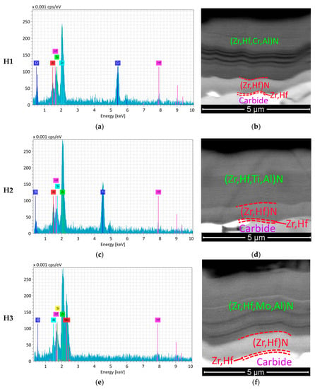
Figure 1.
The results of the analysis of the composition (left) and functional layer structure (right) of the investigated coatings (SEM-BSE). (a) H1 composition; (b) H1 structure; (c) H2 composition; (d) H2 structure; (e) H3 composition; (f) H3 structure.

Table 1.
Elemental composition of the coatings being studied (at.%), their hardness (GPa), and critical fracture load LC2 (N).
The coatings H1–H3 have close values of hardness and critical fracture load LC2 (Table 1).
The study of the wear resistance of coated and uncoated tools during the turning of steel 1045 has revealed that all coated tools have better wear resistance compared to uncoated tools (Figure 2). After 5 min of cutting, the average flank wear VB detected for the uncoated tool was 1.8 times higher than for the tools with the coatings H1, H2, and H3 and 1.5 times higher than for the ZrN-coated tool. On average, the tools with Coatings H1, H2, and H3 demonstrated the rate of wear 1.2 times lower after 5 min of cutting compared to that of the ZrN-coated tool. The ZrN-coated tool and the tool with Coating H1 had a tool life 1.5 times longer and the tools with Coating H2 and H3–2 times longer compared to the uncoated tools. The tool with Coating H1 demonstrated the highest wear resistance after 5 min of cutting; however, after 7.5 min of cutting, its wear resistance noticeably decreased to the level of the ZrN-coated tool. Since a catastrophic wear was detected on two out of five specimens after 5 min of cutting, it can be assumed it is not advisable to use uncoated tools under the given cutting conditions. At the same time, all the coated tools under consideration demonstrated fairly balanced patterns of wear with no signs of catastrophic wear or failure.
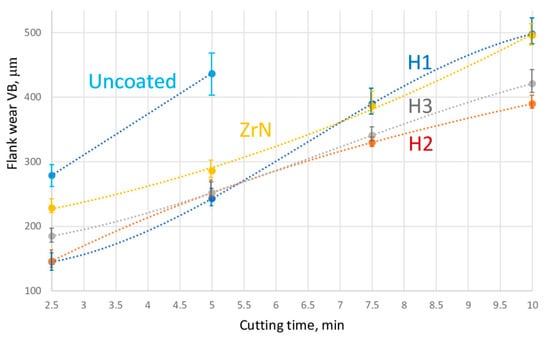
Figure 2.
Relationship between the flank wear and the cutting time during the turning of steel 1045.
We consider in more detail the patterns of rake wear for the tools with considered Coatings H1, H2, and H3 after 10 min of cutting (Figure 3). An obvious notch wear is typical for the rake face, while no formation of noticeable wear crater is detected. Such a pattern of wear is typical for high cutting speeds and, respectively, active diffusion and oxidation processes at elevated temperatures [65,66]. The specimens with Coatings H1, H2, and H3 demonstrate fairly close patterns of wear. However, for the specimen with Coating H3, the wear rate is slightly higher (KB = 520 μm) than for the specimens with Coatings H1 and H2 (KB = 450 μm). In terms of notchwear, the more active wear was detected on the specimens with Coatings H1 and H2, while the specimen with Coating H3 demonstrated less active wear.
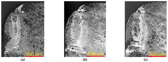

Figure 3.
Pattern of rake wear after 10 min of cutting for the tools with (a,d) Coating H1, (b,e) Coating H2, and (c,f) Coating H3.
For a better understanding of the specifics of wear and fracture of the coated specimen during the turning, we consider cross-sections passing through the center of the wear area on the rake surface, perpendicular to the cutting edge. In general, all three coatings under consideration have fairly close patterns of cracking and delamination formation, but certain differences are also obvious.
Active cracking is detected in Coating H1 (Figure 4), with exclusively longitudinal cracks, the formation of which is usually related to the action of internal compressive stresses [67,68,69]. It is the active cracking resulted from the action of compressive stresses that can explain the noticeable decrease in the wear resistance of the tool with Coating H1 after 5 min of cutting.
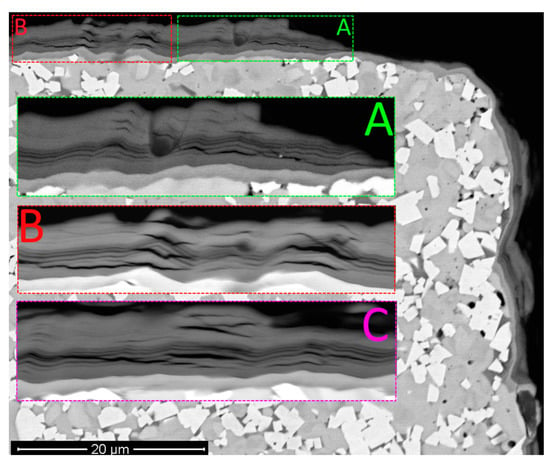
Figure 4.
Pattern of wear for the tool with Coating H1 after 10 min of cutting. Large longitudinal cracks: (A) area A; (B) area B; (C) area C. Area C is located to the left of the area under consideration (SEM-BSE).
The structure of the coating hardly contains any transverse cracks (Figure 5), the formation of which contributes to a larger degree to the fracture of the coating and failure of the cutting tool [70]. According to the analysis of the data exhibited in Figure 4 and Figure 5, the dominant direction of crack propagation in Coating H1 is the direction parallel to the surface of the substrate. The nanolayer structure of the coating does not have any noticeable effect on the pattern of crack propagation. Cracks propagate by cutting through the nanolayers of the coating. The Focused Ion Beam (FIB) cross-section analysis of the coating (Figure 5e,f) also detects a number of longitudinal cracks, which can indicate that the cracks are contained in the structure of the coatings, rather than being formed during the obtaining of the cross-sections for SEM.
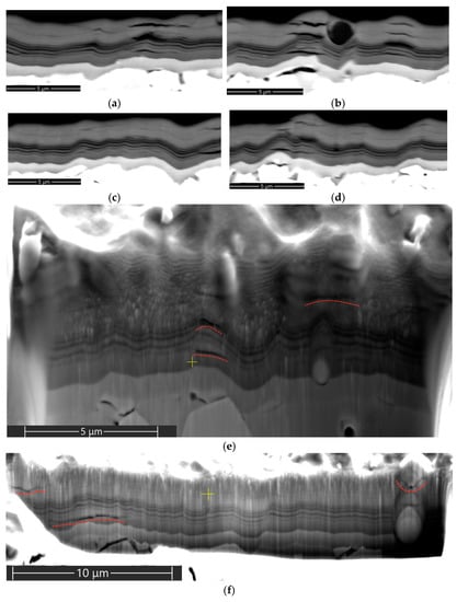
Figure 5.
Cracking and delaminations in the structure of Coating H1 after 10 min of cutting, on the rake face of the tool: (a–d) cross-sections; (e,f) FIB cross-section cuts (SEM-BSE). Large longitudinal cracks.
The patterns of cracking slightly differ for Coatings H1 and H2. In particular, a slightly less active cracking takes place in Coating H2, with interlayer delaminations dominating, rather than longitudinal cracks (Figure 6 and Figure 7).
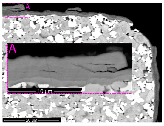
Figure 6.
Pattern of wear for the tool with Coating H2 after 10 min of cutting (SEM-BSE). Longitudinal cracks combined with delamination between nanolayers. (A) area A: delamination between nanolayers.
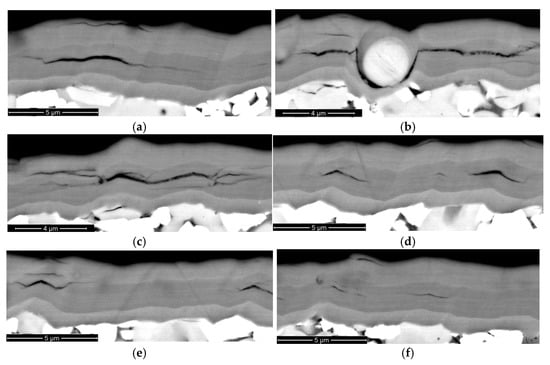
Figure 7.
Cracking and delaminations in the structure of Coating H2 after 10 min of cutting, on the rake face of the tool (SEM-BSE). Longitudinal cracks combined with delamination between nanolayers: (a) delamination between nanolayers; (b) the effect of the embedded microdroplet on delamination; (c) delamination combined with cracks; (d–f) insignificant (2–4 μm long) delamination delamination between nanolayers.
Thus, it can be assumed that the interlayer (cohesive) bond between the nanolayers is weaker and that the internal compressive stresses are lower in Coating H2. Given that the tool with Coating H2 demonstrated noticeably better wear resistance during the turning compared to the tool with Coating H1, it can be concluded that the mentioned parameters have a significant influence on the cutting properties of the tool. Earlier, in [70], it was noted that the formation of delaminations between the nanolayers of the coating could, to a certain extent, favorably affect the wear resistance of the coating due to a decrease in the internal stresses.
In terms of the pattern of cracking, Coating H3 occupies an intermediate position between Coatings H1 and H2 (Figure 8 and Figure 9). In particular, the structure of worn Coating H3 contains both delaminations between nanolayers and longitudinal cracks. At the same time, the process of cracking is less intensive compared to Coating H1 and is approximately equal to that of Coating H2.
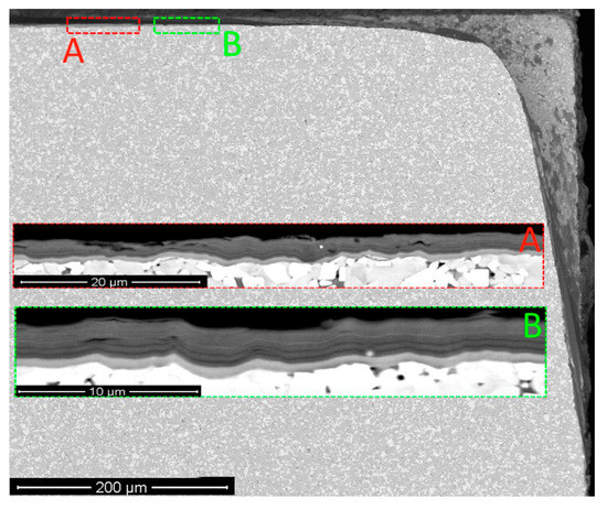
Figure 8.
Pattern of wear on the tool with Coating H3 after 10 min of cutting (SEM-BSE). Preferably delamination between nanolayers: (A) area A; (B) area B.
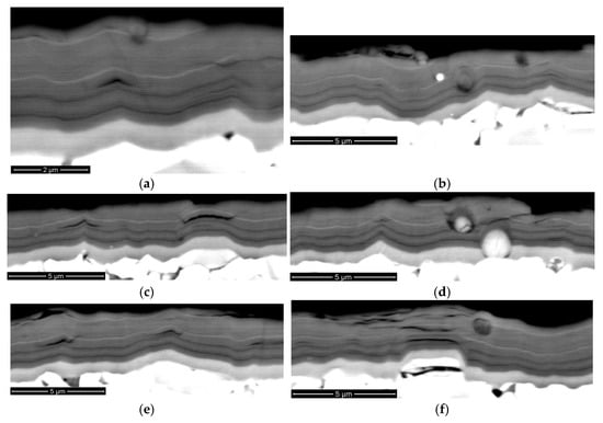
Figure 9.
Cracking and delaminations in the structure of Coating H3 after 10 min of cutting, on the rake face of the tool (SEM-BSE). Preferably delamination between nanolayers. Longitudinal cracks combined with delamination between nanolayers: (a) insignificant (2–4 μm long) delamination between nanolayers; (b,d) the effect of the embedded microdroplet on delamination; (c) delamination combined with cracks; (e,f) insignificant (2–4 μm long) delamination between nanolayers.
The described pattern and intensity of the cracking process in Coating H3 correlate well with a considerably high wear resistance of the tool with Coating H3, which is only slightly inferior to the wear resistance of the tool with Coating H2.
4. Discussion
We consider several possible causes for the formation of interlayer delaminations in the coatings under study and the differences in the patterns of those delaminations.
The formation of delaminations between the nanolayers could be caused by a difference in the coefficients of thermal expansion (CTEs) α between the materials of separate layers. The data available (Table 2) exhibit the greatest difference in the CTEs between ZrN (α = 8.1) and Mo2N (α = 6.4). A slightly less difference is detected between ZrN (α = 8.1) and TiN (α = 7.1). The closest CTEs are detected for ZrN (α = 8.1) and CrN (α = 7.5). That is, using the given approach, we can predict the highest tendency to delamination between the layers of ZrN and Mo2N, and the lowest tendency between the layers of ZrN and CrN. In fact, there is an almost opposite situation when the highest number of delaminations is observed for the coating with alternating layers of (Zr,Hf)N and CrN. It is clear that the coefficient of thermal expansion α for (Zr,Hf)N differs from that for ZrN, and aluminum contained in the coating composition also has a certain effect. The contents of (Zr,Hf)N and Al are identical for all the coatings under consideration, and, therefore, only the difference in the CETs α for CrN, TiN, and Mo2N has an effect on the different expansion of some separate layers.

Table 2.
Coefficients of thermal expansion α for metals and their nitrides depending on temperature (×10−6/K) [71,72].
Another possible cause for the formation of interlayer delaminations could be an inconsistency in such parameters of the material as the atomic radius and electronegativity in terms of the Hume-Rothery rules [73,74] and the Pauling scale [75,76,77]. The analysis of the data contained in Table 3 exhibits that Zr and Hf have very close parameters and are almost ideally combined. In terms of the considered approach, Ti and Al have the parameters closest to Zr and Hf, while the parameters of Cr, and, in particular, Mo, greatly differ from those of Zr and Hf. It is Coating H2, containing titanium, in which the most active delaminations occur, while Coating H3 containing Mo has fewer delaminations and more transverse cracks, cutting through the structure of the coating.

Table 3.
Comparison of the atomic radii and electronegativity of the elements contained in the coatings under consideration (compiled on the basis of analysis of information presented in [78]).
Thus, Coating H3, containing the layers of Mo2N, which differ significantly from the layers of (Zr,Hf)N, both, in terms of the coefficient of thermal expansion and in terms of the Pauling scale, did not demonstrate a high tendency to interlayer delamination. At the same time, the mentioned tendency was identified for Coating H2, containing the layers of TiN quite close in their properties to the layers of (Zr,Hf)N.
Another parameter influencing the formation of interlayer delaminations is the Gibbs energy, described by the well-known formula [79]:
A negative value of ΔG° indicates a decrease in the action of adhesion as a result of the formation of interphase tension. As the coating is operated under elevated temperatures, then it is reasonable to consider ΔGT°, an isobaric reaction potential, at the temperature at which the cutting tool is operated. Therefore, the challenge is reduced to the determination of nitride phases, characterized by an optimal combination of properties, as too strong adhesion bonds will prevent the formation of separate delaminations able to reduce the level of internal stresses, and too weak adhesion bonds will provoke rapid fracture of the coating through its global delamination. The analytical solution of the described problem is being hampered by the lack of necessary coefficients for most nitride compounds, especially multicomponent ones [79,80]. However, during the determination of the mentioned coefficients, it is the calculation of isobaric reaction potential at the temperature at which the cutting tool is operated that can become an important element in modeling the fracture of multilayer coatings and developing the coatings with optimal properties. Similar problems in relation to the NiTi coating were considered in [81,82].
Based on the foregoing, it can be assumed that, to determine the optimal coating composition in terms of adhesive bonds between nanolayers, it is not sufficient to use a single method. Only the development of the methods to consider various approaches will be able to effectively solve the problem.
Given that tools with H1 and H2 coatings showed fairly similar wear rates, it is necessary to take into account the certain technological complexity of using molybdenum cathodes. Molybdenum is characterized by the active formation of microdroplets during the deposition of coatings; moreover, due to the high melting and boiling points, the use of molybdenum is associated with higher energy consumption [83,84].
5. Conclusions
The properties of three coatings based on the systems of Zr,Hf,Al were investigated, including Zr,Hf-(Zr,Hf)N-(Zr,Hf,Cr,Al)N, referred to as Coating H1, Zr,Hf-(Zr,Hf)N-(Zr,Hf,Ti,Al)N, referred to as Coating H2, and Zr,Hf-(Zr,Hf)N-(Zr,Hf,Mo,Al)N, referred to as Coating H3. Following the analysis of the studies carried out, we can make the following conclusions:
- The considered coatings have close values of hardness and critical fracture load LC2;
- After 5 min of cutting, the average flank wear VB detected for the uncoated tool was 1.8 times higher than that for the tools with Coatings H1, H2, and H3 and 1.5 times higher than for the ZrN-coated tool. For the tools with Coatings H1, H2, and H3, the rate of wear was in average 1.2 times lower after 5 min of cutting in comparison with that for the tool with the commercial ZrN coating. The ZrN-coated tool and the tool with Coating H1 demonstrated the tool life 1.5 times higher, and the tools with Coatings H2 and H3–2 times higher compared to that of the uncoated tool;
- A process of notchwear is typical for the rake faces of the tools with the coatings under study, with no formation of any noticeable wear crater. The patterns of rake wear were fairly close for all the tools with Coatings H1, H2, and H3. However, for the tool with Coating H3, the rate of wear was slightly higher (KB = 520 μm) than that for the tools with Coatings H1 and H2 (KB = 450 μm). In terms on notchwear, the more active wear was detected for the tools with Coatings H1 and H2, while less active wear was demonstrated by the tool with Coating H3;
- Coating H1 undergoes active wear during the cutting process due to the formation of a large number of transverse cracks, cutting through the nanolayer structure of the coating. A formation of interlayer delaminations is more typical for Coating H2, whereas a combination of interlayer delaminations and longitudinal cracks is more typical for Coating H3. In general, Coatings H2 and H3 demonstrate less active cracking than Coating H1;
- Thus, the highest wear resistance is detected for the tool with Coating H2, and Coating H2 demonstrates the most favorable pattern of cracking, i.e., an insignificant amount of interlayer delaminations. In typical cutting operations of steel 1045, tools with H2 coating would likely give the best overall performance and tool life. Despite the additional cost to apply this coating, we anticipate that cutting speed and the added tool life would make this choice economic.
Further research may be directed at varying such coating parameters as the value of the nanolayer period λ and the ratio of elements in the coating composition. The research focused on Coatings H2 and H3 is more advisable.
Author Contributions
Conceptualisation, methodology A.V.; methodology, N.S., J.B. and M.V.; validation, N.S. and C.S.; investigation, N.S., A.S., C.S., M.V., J.B.; resources, A.V.; data curation, A.S., N.S.; writing—original draft preparation, A.V.; project administration, A.V.; funding acquisition, A.V. All authors have read and agreed to the published version of the manuscript.
Funding
The study was supported by a grant from the Russian Science Foundation (project No. 21-19-00612). The study used the equipment from the Centre for collective use of Moscow State Technological University STANKIN (agreement No. 075-15-2021-695, 26/07/2021). The coating structure was investigated using the equipment of the Centre for collective use of scientific equipment “Material Science and Metallurgy”, purchased with the financial support of the Ministry of Science and Higher Education of the Russian Federation (GK 075-15-2021-696).
Institutional Review Board Statement
Not applicable.
Informed Consent Statement
Not applicable.
Data Availability Statement
Data available on request due to restrictions privacy or ethical.
Conflicts of Interest
The authors declare no conflict of interest.
References
- Bouzakis, K.D.; Michailidis, N.; Skordaris, G.; Bouzakis, E.; Biermann, D.; M’Saoubi, R. Cutting with coated tools: Coating technologies, characterization methods and performance optimization. CIRP Ann. Manuf. Technol. 2012, 61, 703–723. [Google Scholar] [CrossRef]
- Tkadletz, M.; Schalk, N.; Daniel, R.; Keckes, J.; Czettl, C.; Mitterer, C. Advanced characterization methods for wear resistant hard coatings: A review on recent progress. Surf. Coat. Technol. 2016, 285, 31–46. [Google Scholar] [CrossRef]
- Zhang, S.; Sun, D.; Fu, Y.; Du, H. Recent advances of superhard nanocomposite coatings: A review. Surf. Coat. Technol. 2003, 167, 113–119. [Google Scholar] [CrossRef]
- Grigoriev, S.N.; Kozochkin, M.P.; Sabirov, F.S.; Kutin, A.A. Diagnostic systems as basis for technological improvement. Procedia CIRP 2012, 1, 599–604. [Google Scholar] [CrossRef]
- Kuzin, V.; Grigoriev, S.N.; Volosova, M.A. The role of the thermal factor in the wear mechanism of ceramic tools: Part 1. Macrolevel. J. Frict. Wear 2014, 35, 505–510. [Google Scholar] [CrossRef]
- Grigoriev, S.; Volosova, M.; Vereschaka, A.; Sitnikov, N.; Milovich, F.; Bublikov, J.; Fyodorov, S.; Seleznev, A. Properties of (Cr,Al,Si)N-(DLC-Si) composite coatings deposited on a cutting ceramic substrate. Ceram. Int. 2020, 46, 18241–18255. [Google Scholar] [CrossRef]
- Grigoriev, S.; Peretyagin, P.; Smirnov, A.; Solís, W.; Díaz, L.; Fernández, A.; Torrecillas, R. Effect of graphene addition on the mechanical and electrical properties of Al2O3-SiCw ceramics. J. Eur. Ceram. Soc. 2017, 37, 2473–2479. [Google Scholar] [CrossRef]
- Skordaris, G.; Bouzakis, K.; Charalampous, P.; Bouzakis, E.; Paraskevopoulou, R.; Lemmer, O.; Bolz, S. Brittleness and fatigue effect of mono- and multi-layer PVD films on the cutting performance of coated cemented carbide inserts. CIRP Ann. 2014, 63, 93–96. [Google Scholar] [CrossRef]
- Hovsepian, P.E.; Ehiasarian, A.; Deeming, A.; Schimpf, C. Novel TiAlCN/VCN nanoscale multilayer PVD coatings deposited by the combined high-power impulse magnetron sputtering/unbalanced magnetron sputtering (HIPIMS/UBM) technology. Vacuum 2008, 82, 1312–1317. [Google Scholar] [CrossRef]
- Araujo, J.A.; Araujo, G.M.; Souza, R.M.; Tschiptschin, A.P. Effect of periodicity on hardness and scratch resistance of CrN/NbNnanoscale multilayer coating deposited by cathodic arc technique. Wear 2015, 330–331, 469–477. [Google Scholar] [CrossRef]
- Vereschaka, A.; Tabakov, V.; Grigoriev, S.; Aksenenko, A.; Sitnikov, N.; Oganyan, G.; Seleznev, A.; Shevchenko, S. Effect of adhesion and the wear-resistant layer thickness ratio on mechanical and performance properties of ZrN-(Zr,Al,Si)N coatings. Surf. Coat. Technol. 2018, 357, 218–234. [Google Scholar] [CrossRef]
- Vereschaka, A.; Tabakov, V.; Grigoriev, S.; Sitnikov, N.; Milovich, F.; Andreev, N.; Sotova, C.; Kutina, N. Investigation of the influence of the thickness of nanolayers in wear-resistant layers of Ti-TiN-(Ti,Cr,Al)N coating on destruction in the cutting and wear of carbide cutting tools. Surf. Coat. Technol. 2020, 385, 125402. [Google Scholar] [CrossRef]
- Beresnev, V.M.; Torianyk, I.N.; Pogrebnjak, A.; Bondar, O.; Bilokur, M.; Sobol, O.; Kolesnikov, D.A.; Lytovchenko, S.; Turbin, P. Structure and physical and mechanical properties of nanocomposite (Zr-Ti-Cr-Nb)N and (Ti-Zr-Al-Nb-Y)N coatings, obtained by vacuum-arc evaporation method. In Nanocomposites, Nanophotonics, Nanobiotechnology, and Applications; Fesenko, O., Yatsenko, L., Eds.; Springer: Cham, Switzerland, 2014; pp. 75–84. [Google Scholar]
- Liang, S.C.; Chang, Z.C.; Tsai, D.C.; Lin, Y.C.; Sung, H.S.; Deng, M.J.; Shieu, F.S. Effects of substrate temperature on the structure and mechanical properties of (TiVCrZrHf)N coatings. Appl. Surf. Sci. 2011, 257, 7709–7713. [Google Scholar] [CrossRef]
- Lai, C.-H.; Lin, S.-J.; Yeh, J.-W.; Chang, S.-Y. Preparation and characterization of AlCrTaTiZr multi-element nitride coatings. Surf. Coat. Technol. 2006, 201, 3275–3280. [Google Scholar] [CrossRef]
- Chang, K.-S.; Chen, K.-T.; Hsu, C.-Y.; Hong, P.-D. Growth (AlCrNbSiTiV)N thin films on the interrupted turning and properties using DCMS and HIPIMS system. Appl. Surf. Sci. 2018, 440, 1–7. [Google Scholar] [CrossRef]
- Koshy, R.A.; Graham, M.E.; Marks, L.D. Temperature activated self-lubrication in CrN/Mo2N nanolayer coatings. Surf. Coat. Technol. 2010, 204, 1359–1365. [Google Scholar] [CrossRef]
- Glatz, S.A.; Moraes, V.; Koller, C.M.; Riedl, H.; Bolvardi, H.; Kolozsvári, S.; Mayrhofer, P.H. Effect of Mo on the thermal stability, oxidation resistance, and tribo-mechanical properties of arc evaporated Ti-Al-N coatings. J. Vac. Sci. Technol. A 2017, 35, 061515. [Google Scholar] [CrossRef]
- Ju, H.; Yu, D.; Xu, J.; Yu, L.; Zuo, B.; Geng, Y.; Huang, T.; Shao, L.; Ren, L.; Du, C.; et al. Crystal structure and tribological properties of ZrAlMoN composite films deposited by magnetron sputtering. Mater. Chem. Phys. 2019, 230, 347–354. [Google Scholar] [CrossRef]
- Grigoriev, S.N.; Sobol, O.V.; Beresnev, V.M.; Serdyuk, I.V.; Pogrebnyak, A.D.; Kolesnikov, D.A.; Nemchenko, U.S. Tribological characteristics of (TiZrHfVNbTa)N coatings applied using the vacuum arc deposition method. J. Frict. Wear 2014, 35, 359–364. [Google Scholar] [CrossRef]
- Franz, R.; Lechthaler, M.; Polzer, C.; Mitterer, C. Oxidation behaviour and tribological properties of arc-evaporated ZrAlN hard coatings. Surf. Coat. Technol. 2012, 206, 2337–2345. [Google Scholar] [CrossRef]
- Grigoriev, S.; Vereschaka, A.; Milovich, F.; Tabakov, V.; Sitnikov, N.; Andreev, N.; Sviridova, T.; Bublikov, J. Investigation of multicomponent nanolayer coatings based on nitrides of Cr, Mo, Zr, Nb, and Al. Surf. Coat. Technol. 2020, 401, 126258. [Google Scholar] [CrossRef]
- Atar, E.; Cimenoglu, H.; Kayali, E.S. An investigation of fretting wear behaviour of a ternary (Zr,Hf)N coating. In Proceedings of the 2005 World Tribology Congress III, Washington, DC, USA, 12–16 September 2005; Volume 2, pp. 395–396. [Google Scholar] [CrossRef]
- Atar, E.; Kayali, E.; Çimenoğlu, H. Reciprocating wear behaviour of (Zr, Hf)N coatings. Wear 2004, 257, 633–639. [Google Scholar] [CrossRef]
- Atar, E.; Çimenoğlu, H.; Kayalı, E.; Kayali, E. Hardness characterisation of thin Zr(Hf,N) coatings. Surf. Coat. Technol. 2003, 162, 167–173. [Google Scholar] [CrossRef]
- Atar, E.; Kayali, E.S.; Cimenoglu, H. Sliding wear behaviour of ZrN and (Zr, 12 wt% Hf)N coatings. Tribol. Int. 2006, 39, 297–302. [Google Scholar] [CrossRef]
- Wu, Z.; Qi, Z.; Zhang, D.; Wang, Z. Microstructure, mechanical properties and oxidation resistance of (Zr, Hf)Nx coatings by magnetron co-sputtering. Surf. Coat. Technol. 2015, 276, 219–227. [Google Scholar] [CrossRef]
- Prathumsit, J.; Gitgeatpong, G.; Phae-Ngam, W.; Chananonnawathorn, C.; Lertvanithphol, T.; Horprathum, M. The effect of thickness on the properties of Zr-Hf-N thin films prepared by reactive co-magnetron sputtering. In Proceedings of the Second Materials Research Society of Thailand International Conference, Pattaya, Thailand, 10–12 July 2019; Maensiri, S., Meevasana, W., Pecharapa, W., Eds.; AIP Publishing: College Park, MD, USA, 2020. [Google Scholar] [CrossRef]
- Atar, E.; Sarioglu, C.; Cimenoglu, H.; Kayali, E. Residual stresses in (Zr,Hf)N films (up to 11.9 at.% Hf) measured by X-ray diffraction using experimentally calculated XECs. Surf. Coat. Technol. 2005, 191, 188–194. [Google Scholar] [CrossRef]
- Fernandez, D.A.R.; Brito, B.S.S.; Santos, I.A.D.; Soares, V.F.D.; Terto, A.R.; de Oliveira, G.B.; Hubler, R.; Batista, W.W.; Ten-tardini, E.K. Effect of hafnium contaminant present in zirconium targets on sputter deposited ZrN thin films. NIMB 2020, 462, 90–94. [Google Scholar] [CrossRef]
- Atar, E.; Kayali, E.S.; Cimenoglu, H. The effect of oxidation on the structure and hardness of (Zr, Hf)N coatings. Defect Diffus. Forum 2010, 297–301, 1395–1399. [Google Scholar] [CrossRef]
- Sarioglu, C. The effect of anisotropy on residual stress values and modification of Serruys approach to residual stress calculations for coatings such as TiN, ZrN and HfN. Surf. Coat. Technol. 2006, 201, 707–717. [Google Scholar] [CrossRef]
- Serruys, W.; Houtte, P.; Aernoudt, E.; Peters, J. Why are x-ray measurements of residual stresses different from mechanical residual stress measurements? CIRP Ann. Manuf. Technol. 1988, 37, 527–530. [Google Scholar] [CrossRef]
- Feng, C.; Zhu, S.; Li, M.; Xin, L.; Wang, F. Effects of incorporation of Si or Hf on the microstructure and mechanical properties of Ti–Al–N films prepared by arc ion plating (AIP). Surf. Coat. Technol. 2008, 202, 3257–3262. [Google Scholar] [CrossRef]
- Xu, Y.X.; Chen, L.; Pei, F.; Du, Y.; Liu, Y.; Yue, J.L. Influence of Hf on the structure, thermal stability and oxidation resistance of Ti-Al-N coatings. Thin Solid Film. 2014, 565, 25–31. [Google Scholar] [CrossRef]
- Guo, F.; Holec, D.; Wang, J.; Li, S.; Du, Y. Impact of V, Hf and Si on oxidation processes in Ti–Al–N: Insights from ab initio molecular dynamics. Surf. Coat. Technol. 2020, 381, 125125. [Google Scholar] [CrossRef]
- Rachbauer, R.; Blutmager, A.; Holec, D.; Mayrhofer, P. Effect of Hf on structure and age hardening of Ti–Al-N thin films. Surf. Coat. Technol. 2012, 206, 2667–2672. [Google Scholar] [CrossRef]
- Lugscheider, E.; Bobzin, K.; Piñero, C.; Klocke, F.; Massmann, T. Development of a superlattice (Ti,Hf,Cr)N coating for cold metal forming applications. Surf. Coat. Technol. 2004, 177–178, 616–622. [Google Scholar] [CrossRef]
- Bobzin, K.; Bagcivan, N.; Immich, P.; Warnke, C.; Klocke, F.; Zeppenfeld, C.; Mattfeld, P. Advancement of a nanolaminated TiHfN/CrN PVD tool coating by a nano-structured CrN top layer in interaction with a biodegradable lubricant for green metal forming. Surf. Coat. Technol. 2009, 203, 3184–3188. [Google Scholar] [CrossRef]
- Liu, Z.; Li, H.; Li, J.; Huang, J.; Kong, J.; Wu, Q.; Xiong, D. Microstructure, mechanical and tribological properties of Hf-Mo-Si-N films with different Si contents. Surf. Coat. Technol. 2020, 401, 126268. [Google Scholar] [CrossRef]
- Liu, Z.; Li, H.; Li, J.; Huang, J.; Kong, J.; Xiong, X. Tribological properties improvement of Mo-alloyed HfN films with a high H/E ratio at elevated temperature. J. Tribol. 2021, 143, 011704. [Google Scholar] [CrossRef]
- Nyemchenko, U.S.; Beresnev, V.M.; Gorban, V.F.; Novikov, V.J.; Yaremenko, O.V. Comparing the tribological properties of the coatings (Ti-Hf-Zr-V-Nb-Ta)N and (Ti-Hf-Zr-V-Nb-Ta)N + DLC. J. Nano Electron. Phys. 2015, 7, 03041. [Google Scholar]
- Komarov, F.F.; Pogrebnyak, A.D.; Konstantinov, S.V. Physics of nanostructures at radiation resistance of high-entropy nanostructured (Ti,Hf,Zr,V,Nb)N coatings. Tech. Phys. 2015, 60, 1519–1524. [Google Scholar] [CrossRef]
- Pogrebnyak, A.D.; Beresnev, V.M.; Kolesnikov, D.A.; Kaverin, M.V.; Shypylenko, A.P.; Oyoshi, K.; Takeda, Y.; Krause-Rehberg, R.; Ponomarev, A.G. The effect of segregation and thermodiffusion on the formation of interfaces in nanostructured (Ti-Hf-Zr-V-Nb)N multielement coatings. Tech. Phys. Lett. 2013, 39, 280–283. [Google Scholar] [CrossRef]
- Pogrebnjak, A.D.; Borisyuk, V.N.; Bagdasaryan, A.A.; Maksakova, O.V.; Smirnova, E.V. The multifractal investigation of surface microgeometry of (Ti-Hf-Zr-V-Nb)N nitride coatings. J. Nano Electron. Phys. 2014, 6, 04018. [Google Scholar]
- Nemchenko, U.S.; Beresnev, V.M.; Klimenko, S.A.; Podchernyaeva, I.A.; Turbin, P.V.; Andreev, A. Wear resistance of the multicomponent coatings of the (Ti-Zr-Hf-V-Nb-Ta)N system at elevated temperature. J. Superhard Mater. 2015, 37, 322–326. [Google Scholar] [CrossRef]
- Grigoriev, S.N.; Vereschaka, A.; Fyodorov, S.V.; Sitnikov, N.; Batako, A.D. Comparative analysis of cutting properties and nature of wear of carbide cutting tools with multi-layered nano-structured and gradient coatings produced by using of various deposition methods. Int. J. Adv. Manuf. Technol. 2016, 90, 3421–3435. [Google Scholar] [CrossRef]
- Grigoriev, S.N.; Metel, A.S.; Fedorov, S.V. Modification of the structure and properties of high-speed steel by combined vac-uum-plasma treatment. Met. Sci. Heat Treat. 2012, 54, 8–12. [Google Scholar] [CrossRef]
- Vereschaka, A.S.; Grigoriev, S.N.; Tabakov, V.P.; Sotova, E.S.; Vereschaka, A.A.; Kulikov, M.Y. Improving the efficiency of the cutting tool made of ceramic when machining hardened steel by applying nano-dispersed multi-layered coatings. Key Eng. Mater. 2013, 581, 68–73. [Google Scholar] [CrossRef]
- Vereschaka, A.S.; Vereschaka, A.A.; Sladkov, D.; Aksenenko, A.; Sitnikov, N. Control of structure and properties of nanostructured multilayer composite coatings applied to cutting tools as a way to improve efficiency of technological cutting operations. J. Nano Res. 2015, 37, 51–57. [Google Scholar] [CrossRef]
- Vereschaka, A.A.; Vereschaka, A.S.; Grigoriev, S.N.; Kirillov, A.K.; Khaustova, O.U. Development and research of environ-mentally friendly dry technological machining system with compensation of physical function of cutting fluids. Procedia CIRP 2013, 7, 311–316. [Google Scholar] [CrossRef]
- Vereschaka, A.; Tabakov, V.; Grigoriev, S.; Sitnikov, N.; Milovich, F.; Andreev, N.; Bublikov, J. Investigation of wear mechanisms for the rake face of a cutting tool with a multilayer composite nanostructured Cr–CrN-(Ti,Cr,Al,Si)N coating in high-speed steel turning. Wear 2019, 438–439, 203069. [Google Scholar] [CrossRef]
- Vereschaka, A.; Tabakov, V.; Grigoriev, S.; Sitnikov, N.; Oganyan, G.; Andreev, N.; Milovich, F. Investigation of wear dynamics for cutting tools with multilayer composite nanostructured coatings in turning constructional steel. Wear 2018, 420, 17–37. [Google Scholar] [CrossRef]
- Vereschaka, A.; Grigoriev, S.; Popov, A.; Batako, A. Nano-scale multilayered composite coatings for cutting tools operating under heavy cutting conditions. Procedia CIRP 2014, 14, 239–244. [Google Scholar] [CrossRef]
- Vereschaka, A.; Tabakov, V.; Grigoriev, S.; Sitnikov, N.; Andreev, N.; Milovich, F. Investigation of wear and diffusion processes on rake faces of carbide inserts with Ti-TiN-(Ti,Al,Si)N composite nanostructured coating. Wear 2018, 416, 72–80. [Google Scholar] [CrossRef]
- Vereschaka, A.; Grigoriev, S.; Tabakov, V.; Migranov, M.; Sitnikov, N.; Milovich, F.; Andreev, N. Influence of the nanostructure of Ti-TiN-(Ti,Al,Cr)N multilayer composite coating on tribological properties and cutting tool life. Tribol. Int. 2020, 150, 106388. [Google Scholar] [CrossRef]
- Vereschaka, A.; Aksenenko, A.; Sitnikov, N.; Migranov, M.; Shevchenko, S.; Sotova, C.; Batako, A.; Andreev, N. Effect of ad-hesion and tribological properties of modified composite nano-structured multi-layer nitride coatings on WC-Co tools life. Tribol. Int. 2018, 128, 313–327. [Google Scholar] [CrossRef]
- Vereshchaka, A.S.; Vereshchaka, A.A.; Kirillov, A.K. Ecologically friendly dry machining by cutting tool from layered com-position ceramic with nano-scale multilayered coatings. Key Eng. Mater. 2012, 496, 67–74. [Google Scholar] [CrossRef]
- Grigoriev, S.N.; Melnik, Y.A.; Metel, A.; Panin, V.V. Broad beam source of fast atoms produced as a result of charge exchange collisions of ions accelerated between two plasmas. Instrum. Exp. Tech. 2009, 52, 602–608. [Google Scholar] [CrossRef]
- Metel, A.S.; Grigoriev, S.N.; Melnik, Y.; Prudnikov, V.V. Glow discharge with electrostatic confinement of electrons in a chamber bombarded by fast electrons. Plasma Phys. Rep. 2011, 37, 628–637. [Google Scholar] [CrossRef]
- Sobol, O.V.; Andreev, A.A.; Grigoriev, S.N.; Gorban, V.F.; Volosova, M.A.; Aleshin, S.V.; Stolbovoi, V.A. Effect of high-voltage pulses on the structure and properties of titanium nitride vacuum-arc coatings. Met. Sci. Heat Treat. 2012, 54, 195–203. [Google Scholar] [CrossRef]
- Metel, A.; Bolbukov, V.; Volosova, M.; Grigoriev, S.; Melnik, Y. Source of metal atoms and fast gas molecules for coating deposition on complex shaped dielectric products. Surf. Coat. Technol. 2013, 225, 34–39. [Google Scholar] [CrossRef]
- Oliver, W.C.; Pharr, G.M. An improved technique for determining hardness and elastic modulus using load and displacement sensing indentation experiments. J. Mater. Res. 1992, 7, 1564–1583. [Google Scholar] [CrossRef]
- ASTM International. C1624-05(2015) Standard Test Method for Adhesion Strength and Mechanical Failure Modes of Ceramic Coatings by Quantitative Single Point Scratch Testing; ASTM International: West Conshohocken, PA, USA, 2010. [Google Scholar]
- Grigoriev, S.; Vereschaka, A.; Milovich, F.; Migranov, M.; Andreev, N.; Bublikov, J.; Sitnikov, N.; Oganyan, G. Investigation of the tribological properties of Ti-TiN-(Ti,Al,Nb,Zr)N composite coating and its efficiency in increasing wear resistance of metal cutting tools. Tribol. Int. 2021, 164, 107236. [Google Scholar] [CrossRef]
- Grigoriev, S.; Vereschaka, A.; Milovich, F.; Sitnikov, N.; Andreev, N.; Bublikov, J.; Kutina, N. Investigation of the properties of the Cr,Mo-(Cr,Mo,Zr,Nb)N-(Cr,Mo,Zr,Nb,Al)N multilayer composite multicomponent coating with nanostructured wear-resistant layer. Wear 2021, 468–469, 203597. [Google Scholar] [CrossRef]
- Vereschaka, A.; Volosova, M.; Chigarev, A.; Sitnikov, N.; Ashmarin, A.; Sotova, C.; Bublikov, J.; Lytkin, D. Influence of the thickness of a nanolayer composite coating on values of residual stress and the nature of coating wear. Coatings 2020, 10, 63. [Google Scholar] [CrossRef]
- George, M.; Coupeau, C.; Colin, J.; Grilhé, J. Mechanical behaviour of metallic thin films on polymeric substrates and the effect of ion beam assistance on crack propagation. Acta Mater. 2005, 53, 411–417. [Google Scholar] [CrossRef]
- Marx, V.M.; Toth, F.; Wiesinger, A.; Berger, J.; Kirchlechner, C.; Cordill, M.J.; Fischer, F.D.; Rammerstorfer, F.G.; Dehm, G. The influence of a brittle Cr interlayer on the deformation behavior of thin Cu films on flexible substrates: Experiment and mode. Acta Mater. 2015, 89, 278–289. [Google Scholar] [CrossRef]
- Vereschaka, A.A.; Grigoriev, S.N.; Sitnikov, N.N.; Batako, A. Delamination and longitudinal cracking in multi-layered com-posite nano-structured coatings and their influence on cutting tool life. Wear 2017, 390, 209–219. [Google Scholar] [CrossRef]
- Kazantsev, E.I. Industrial Furnaces. Reference Manual for Calculations and Design; Mir Publishers: Moscow, Russia, 1975. [Google Scholar]
- Tumanov, A.T. Refractory Materials in Mechanical Engineering; Mashinostroyeniye: Moscow, Russia, 1967. [Google Scholar]
- Hume-Rothery, W. The liquid state of the elements. J. Phys. Chem. 1940, 44, 824–825. [Google Scholar] [CrossRef]
- Mann, J.B.; Meek, T.L.; Allen, L.C. Configuration energies of the main group elements. J. Am. Chem. Soc. 2000, 122, 2780–2783. [Google Scholar] [CrossRef]
- Yeh, J.-W.; Chen, S.K.; Lin, S.-J.; Gan, J.-Y.; Chin, T.-S.; Shun, T.-T.; Tsau, C.-H.; Chang, S.-Y. Nanostructured high-entropy alloys with multiple principal elements: Novel alloy design concepts and outcomes. Adv. Eng. Mater. 2004, 6, 299–303. [Google Scholar] [CrossRef]
- Yang, X.; Zhang, Y. Prediction of high-entropy stabilized solid-solution in multi-component alloys. Mater. Chem. Phys. 2012, 132, 233–238. [Google Scholar] [CrossRef]
- Takeuchi, A.; Amiya, K.; Wada, T.; Yubuta, K.; Zhang, W.; Makino, A. Alloy designs of high-entropy crystalline and bulk glassy alloys by evaluating mixing enthalpy and delta parameter for quinary to decimal equi-atomic alloys. Mater. Trans. 2014, 55, 165–170. [Google Scholar] [CrossRef]
- Wieser, M.; Holden, N.; Coplen, T.B.; Bohlke, J.K.; Berglund, M.; Brand, W.A.; De Bièvre, P.; Gröning, M.; Loss, R.D.; Meija, J.; et al. Atomic weights of the elements 2011 (IUPAC Technical Report). Pure Appl. Chem. 2013, 85, 1047–1078. [Google Scholar] [CrossRef]
- Chang, Y.A.; Chen, S.; Zhang, F.; Yan, X.; Xie, F.; Schmid-Fetzer, R.; Oates, W.A. Phase diagram calculation: Past, present and future. Prog. Mater. Sci. 2004, 49, 313–345. [Google Scholar] [CrossRef]
- Zhang, F.; Zhang, C.; Chen, S.; Zhu, J.; Cao, W.; Kattner, U. An understanding of high entropy alloys from phase diagram calculations. Calphad 2013, 45, 1–10. [Google Scholar] [CrossRef]
- Samal, S.; Tyc, O.; Cizek, J.; Klecka, J.; Lukáč, F.; Molnárová, O.; de Prado, E.; Weiss, Z.; Kopeček, J.; Heller, L.; et al. Fabrication of thermal plasma sprayed NiTi coatings possessing functional properties. Coatings 2021, 11, 610. [Google Scholar] [CrossRef]
- Samal, S.; Cibulková, J.; Čtvrtlík, R.; Tomáštík, J.; Václavek, L.; Kopeček, J.; Šittner, P. Tribological behavior of NiTi alloy produced by spark plasma sintering method. Coatings 2021, 11, 1246. [Google Scholar] [CrossRef]
- Vereschaka, A.; Milovich, F.; Migranov, M.; Andreev, N.; Alexandrov, I.; Muranov, A.; Mikhailov, M.; Tatarkanov, A. Investigation of the tribological and operational properties of (Mex,Moy,Al1-(x + y))N (Me–Ti, Zr or Cr) coatings. Tribol. Int. 2022, 165, 107305. [Google Scholar] [CrossRef]
- Grigoriev, S.; Vereschaka, A.; Milovich, F.; Andreev, N.; Bublikov, J.; Sitnikov, N.; Sotova, C.; Kutina, N. Investigation of wear mechanisms of multilayer nanostructured wear-resistant coatings during turning of steel. Part 2: Diffusion, oxidation processes and cracking in Ti-TiN-(Ti,Cr,Mo,Al)N coating. Wear 2021, 486–487, 204096. [Google Scholar] [CrossRef]
Publisher’s Note: MDPI stays neutral with regard to jurisdictional claims in published maps and institutional affiliations. |
© 2021 by the authors. Licensee MDPI, Basel, Switzerland. This article is an open access article distributed under the terms and conditions of the Creative Commons Attribution (CC BY) license (https://creativecommons.org/licenses/by/4.0/).