Article

Galvanic Corrosion Behaviour of Different Types of Coatings Used in Safety Systems Manufacturing

by
Diana-Petronela Burduhos-Nergis
,
Dumitru-Doru Burduhos-Nergis
and
Costica Bejinariu
*
Faculty of Materials Science and Engineering, “Gheorghe Asachi” Technical University, 700050 Iasi, Romania
*
Author to whom correspondence should be addressed.
Coatings 2021, 11(12), 1542; https://doi.org/10.3390/coatings11121542
Submission received: 15 November 2021 / Revised: 7 December 2021 / Accepted: 14 December 2021 / Published: 15 December 2021
(This article belongs to the Special Issue Advances in Corrosion Resistant Coatings)

Abstract

:
Worker safety is one of the main aspects to be taken into account in any activity carried out at work. When we talk about the safety of the worker at activities carried out at height, the condition and characteristics of the personal protective equipment against falling from a height are one of the main causes of work accidents resulting in serious injuries or death. Carabiners are the main components of the safety system; their role is to connect the other components of the system or to make the connection between the system and the anchor point. Therefore, to be used safely, the carabiners’ material must have high corrosion resistance in different environments. This paper is part of a complex study that aims to improve the corrosion properties of carbon steel used in the manufacture of carabiners. Previous studies have shown that the corrosion resistance of carbon steel in various corrosive environments has been improved by the deposition of different types of phosphate layers, as well as other subsequently deposited layers. The aim of this paper is to study the galvanic corrosion evaluation between different galvanic couples (duralumin-coated samples, aluminium bronze-coated samples, and carbon steel-coated samples) tested in three different corrosive media. Moreover, the study approaches for the first time the galvanic corrosion of systems that can be formed between the materials used in the manufacture of carabiners. Accordingly, it was observed that, overall, the samples coated with a Zn phosphate layer exhibited the best performance in all the corrosive environments (saltwater and fire extinguishing solution).

1. Introduction

One of the most important methods of protection against falling from the height of workers is the use of individual protective equipment against falling or safety systems. These systems contain multiple components made of low-corrosion resistance metals, such as carabiners, ropes, anchoring devices etc. [1]. The carabiners are metal connectors that are used to quickly connect the safety system to the anchoring point. They also link the other components of the safety system.
The main materials from which the carabiners are made are steel or aluminium alloys [2]. The choice of carabiners from a certain material is made depending on the load it must withstand. For example, in areas such as civil engineering, oil industry, arboriculture, or during firefighting and rescue operations, high mechanical properties are needed, so steel carabiners are mainly used [3]. However, their use under certain conditions can lead to work accidents that can have serious consequences (disability or even death). Following the statistics of work accidents, it can be seen that a large number of work accidents resulting from falling from a height of workers is due to the failure of personal protective equipment [4].
Thus, the European Standard 362 of 2006 recommends the withdrawal of carabiners from use if the surface of the material from which the carabiners are made is corroded or if they have been hit or dropped, there is a suspicion of the appearance of internal cracks in the material.
Over time, the carabiners have undergone several changes in terms of design, manufacturing process, or material used, to eliminate these disadvantages, i.e., low corrosion resistance and internal crack occurrence [5,6,7,8]. Therefore, all this has led to an increase in the cost of carabiners, due to the use of expensive materials and technologies. A comparative study between the carabiners made of composites and those made of metals is presented in [5]. Accordingly, it was observed that a viable cost-efficient production of carabiners cannot be assured at a large scale, since both labour and materials costs are significantly higher. Additionally, as observed in [9], safety plays an important factor in choosing a product, but it will also contribute to its complexity, robustness, and other factors that will increase its market price. Therefore, the most adequate methods remain the improvement of conventional materials used for the manufacture of carabiners.
Even though the corrosion resistance of carbon steel is low, it still is one of the most used materials for carabiners manufacturing, due to its high mechanical properties and low cost [3].
Thus, to keep a low cost of carabiners, but also to reduce the possibility of accidents at work due to falling from a height or due to the failure of steel carabiners, a comprehensive study was conducted which aimed to improve the corrosion resistance of the carbon steel from which the carabiners are made, by depositing a layer of phosphate on the material surface.
Coating with phosphate layers is one of the most widespread methods of corrosion protection due to its many benefits, such as low cost, simplicity of the phosphating process, non-modification of the mechanical properties of the material, the possibility of depositing new layers, etc. [10,11,12].
The deposition of phosphate layers on the surface of carbon steel gave us the possibility of further coatings [12,13]. Therefore, the phosphate layer not only improved the corrosion resistance properties of the steel but also facilitated the deposition of a layer of elastomer-based paint that reduce the possibility of internal crack occurrence in the material.
Additionally, given that the surface of the phosphate layer has a high roughness, to reduce the coefficient of friction between the carabiner and the rope or another component of the safety system, which could lead to premature wear, on the surface of the phosphate layer was deposited a layer of molybdenum disulphide-based lubricant.
Although previous studies [14,15,16] have shown that the corrosion resistance, in various corrosive environments, of the carbon steel carabiners has been significantly improved by the deposition of phosphate layers and other subsequent layers. However, knowing that the carabiners or other components of the safety systems contain pieces made of different metals, and the fact that the contact zone between these different metals will act as a galvanic couple when exposed to corrosive media, for a complete evaluation, it is also essential to analyse the galvanic corrosion of the couples which can appear between the metals used in safety systems. Previously [17], the behaviour of couples made of aluminium and different types of steels was studied in salt spray (fog) artificial atmospheres. According to the study, after 48 h of exposure to the severe atmospheres, both the aluminium and AISI 1045 steel samples showed white or iron rust, respectively. However, the AISI 304 stainless steel samples showed good performance. Therefore, the pair between Al5754-AISI 304 stainless steel was recommended as the most suitable couple for this corrosive media, while for much more extended service life, the supplementary suitable corrosive resistant coating has been suggested. In another study [18], the galvanic corrosion between 4150 steel, zinc, A380 aluminium, and AZ91D magnesium alloy exposed to salt spray media was evaluated. Accordingly, it was observed that once initiated, the galvanic corrosion rate depends on exposure time and surface. The galvanically affected zone depends on the ratio between the exposed surface of the anode and that of the cathode, i.e., a larger cathode, will conduct to a large affected area on the anode. Moreover, of all the materials that have been studied, the 4150 steels exhibited the lowest corrosive resistance. Similar behaviour was also observed in [19], whereby decreasing the anode/cathode area ratio a higher current density was obtained. Additionally, in [20] the galvanic corrosion behaviour of laser-welded austenitic stainless steel with duplex or super duplex stainless steel was evaluated. In [21], 6061-T6 aluminium alloy welding joints were obtained and exposed to 3.5 wt.% NaCl solution to evaluate the galvanic corrosion. Moreover, in [22] has been observed that 420 ferritic stainless steel is more anodic than 304 L austenitic stainless steel when coupled in HCl media. According to the literature, multiple studies evaluate the galvanic corrosion of steel coupled with other materials. However, to our knowledge, there is no study that evaluates its galvanic corrosion in saltwater and fire extinguishing solution when coupled with phosphate layers. Therefore, this study reveals the corrosion behaviour of the phosphate coated samples under galvanically coupled conditions. The cathode materials used are duralumin, aluminium bronze, and carbon steel. The galvanic couples used were chosen for the following reasons:
-
carbon steel-coated samples: if the carbon steel is not completely covered with the deposited layers;
-
duralumin–steel/coated samples and aluminium bronze–steel/coated samples: because even if the carabiner is made of carbon steel, the rivets or the locking system are made of a different material.
Due to the large use of carbon steel carabiners, the corrosive environments used in this study are saltwater and fire extinguishing solutions.

2. Materials and Methods

2.1. Material

Given that carbon steel carabiners are used in a variety of fields due to their low manufacturing cost and high mechanical properties, carbon steel was used as the base material in this study. Its chemical composition was evaluated using a Foundry-Master Baird Emission Spectrophotometer, model DW6 (Oxford Instruments GmbH, Wiesbaden, Germany). According to the obtained results, the base material contains 0.45 wt.% carbon, 0.98 wt.% manganese, 0.22 wt.% silicone, 0.17 wt.% chrome, 0.15 wt.% copper, 0.02 wt.% phosphorus, and iron (balance).

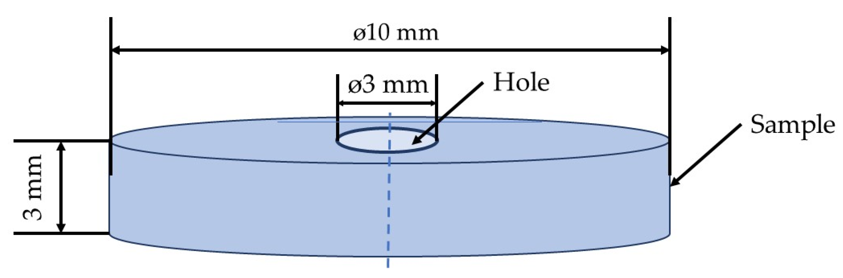
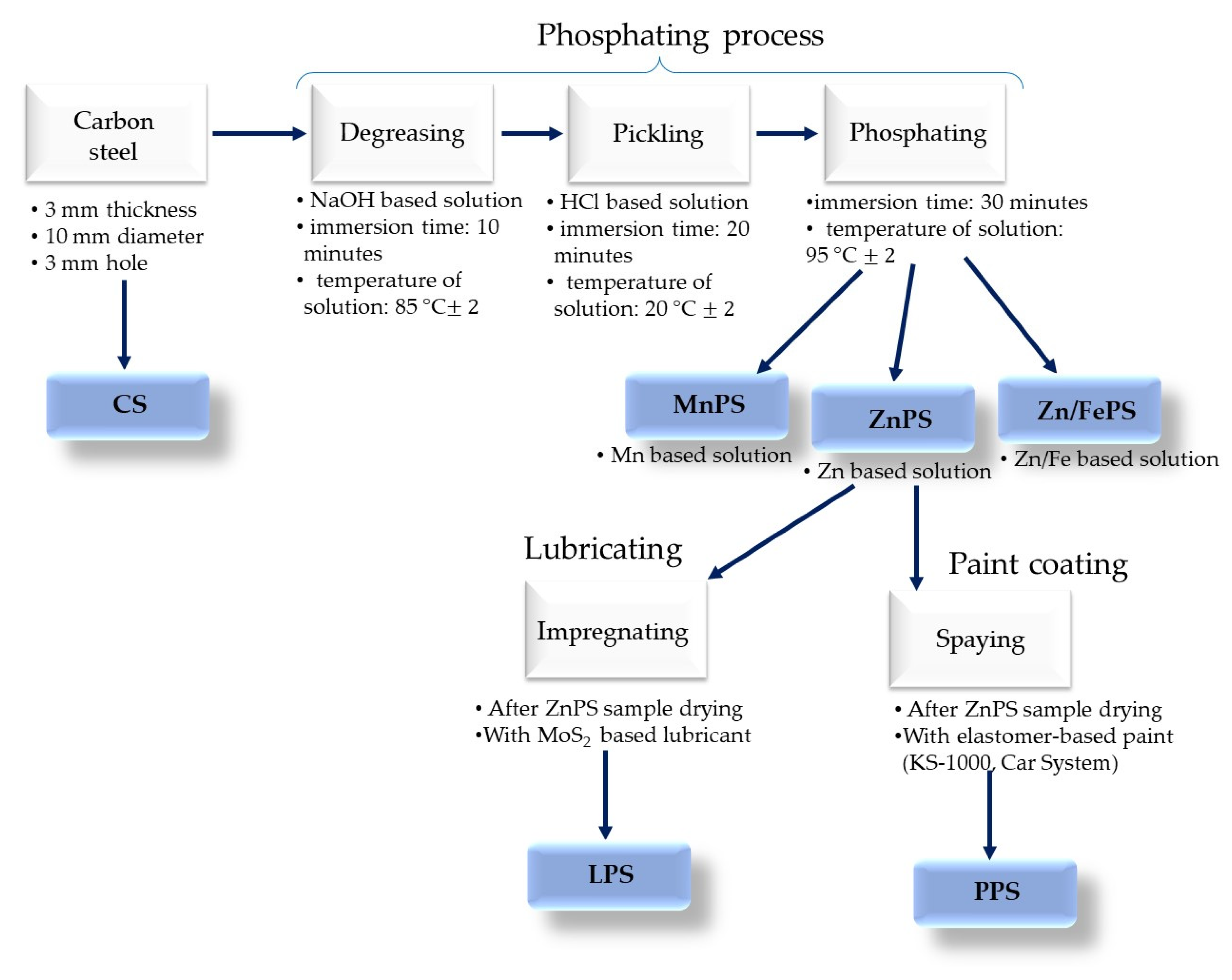
2.2. Sample Preparation

Before being covered with different protective layers, the carbon steel bars were cut into specimens with dimensions of 10 mm in diameter and 3 mm thick, and to make the couplings, a hole with 3 mm in diameter was made inside the samples (Figure 1). To improve the corrosion resistance properties, the samples were subjected to the phosphating process, on their surface being deposited a layer of phosphate with different chemical compositions, depending on the phosphating solution used.
The phosphating solutions used in this study to obtain the phosphate layers contains H3PO4, HNO3, NaOH, NaNO2, Na5P3O10, in different quantities depending on the type of metal ions used (MnPS–Mn2+, Fe2+, Fe3+ and Ni2+ ions; ZnPS–Zn2+ ions; Zn/FePS–Zn2+, Fe2+ and Fe3+ ions).
Considering that the carabiners’ material needs a high impact resistance, which reduces the risk of internal cracks if they are dropped from a height of more than two metres, the samples of phosphate steel with the zinc-based solution were coated by spraying with a layer of elastomer-based paint. Additionally, given that the surface of the phosphate layer is rough, to reduce the coefficient of friction between the carabiner’s material and the rope material, the phosphate sample with the zinc-based solution was impregnated in molybdenum bisulphide-based lubricant.
The process for obtaining the samples tested in this paper is presented in Figure 2.
To make the expression easier, the analysed samples and the corrosion media were symbolized as presented in Table 1.

2.3. Methods

When an iron-based alloy corrodes in an electrolytic medium, two processes take place simultaneously: the dissolution of iron at the anode and a reduction process at the cathode. In an alkaline or neutral medium at the cathode, there is a reduction of dissolved oxygen from the solution, while in an acid medium there is a reduction of hydrogen ions [23].
The area ratio is very important regarding the probability of bimetallic corrosion; a much larger surface area of the cathode than that of the anode allows the reduction of a larger amount of oxygen, a higher galvanic current, and as a result a higher corrosion rate. In the present study, all samples and coupling alloys had the same surface, respectively 0.503 cm2.
A VoltaLab 21 potentiometer (PGP 201) (Radiometer Analytical SAS, Lyon, France) was used to determine the characteristic parameters of galvanic corrosion, respectively the couple potential (Ecouple) and the couple current density (jcouple), and the software which was used for the acquisition and processing of experimental data is VoltaMaster 4.
To evaluate the galvanic corrosion parameters, the Evans and Tafel extrapolation methods were used. The polarisation curves were obtained for all the studied samples, in the same corrosive media and with the same parameters such as temperature, scanning rate etc. A three-electrode electrochemical cell Type C145/170 (Radiometer, Lyon, France) was used for these measurements. In the glass cell, the working electrode has been fixed using Teflon washers and screws, accordingly, only a flat surface of 0.503 mm2 was exposed from the sample. Additionally, in the same cell, two more electrodes have been introduced: the auxiliary electrode (platinum, with an area of 0.8 cm2) and the reference electrode (saturated calomel).
The polarisation curves are represented in the Evans diagram by the electrode potential as a function of the current density logarithm (E = f (log j)). Accordingly, two Tafel slopes are obtained and their intersection gives the value of the couple potential and the current density logarithm depending on the Evans coordinates.
The galvanic couples made between the analysed samples (C45, ZnPS, Zn/FePS, MnPS, LPS, and PPS) with duralumin and aluminium bronze were studied. The composition of the two coupling alloys was determined with a Foundry-Master Baird Emission Spectrophotometer, model DW6 (Oxford Instruments GmbH) and is shown in Table 2.
To evaluate how the galvanic corrosion can influence the corrosion of the coated samples when the coating film is damaged and a local base metal/coated metal coupling can occur, the galvanic couples made between C45 and coated C45 samples were analysed.
The galvanic corrosion was studied in the following corrosive environments: saltwater (SW) and fire extinguishing solution (FES).
To highlight the morphological differences between the layers deposited with different phosphate solutions, the microstructural analysis of the phosphate layers has been performed using a scanning electron microscope (SEM, TESCAN VEGA 3 LMH, Bruker/Roentec Co., Berlin, Germany) and an optical microscope (Zeiss Axio Imager A1, Carl-Zeiss-Strasse, Oberkochen, Germany).

3. Results and Discussion

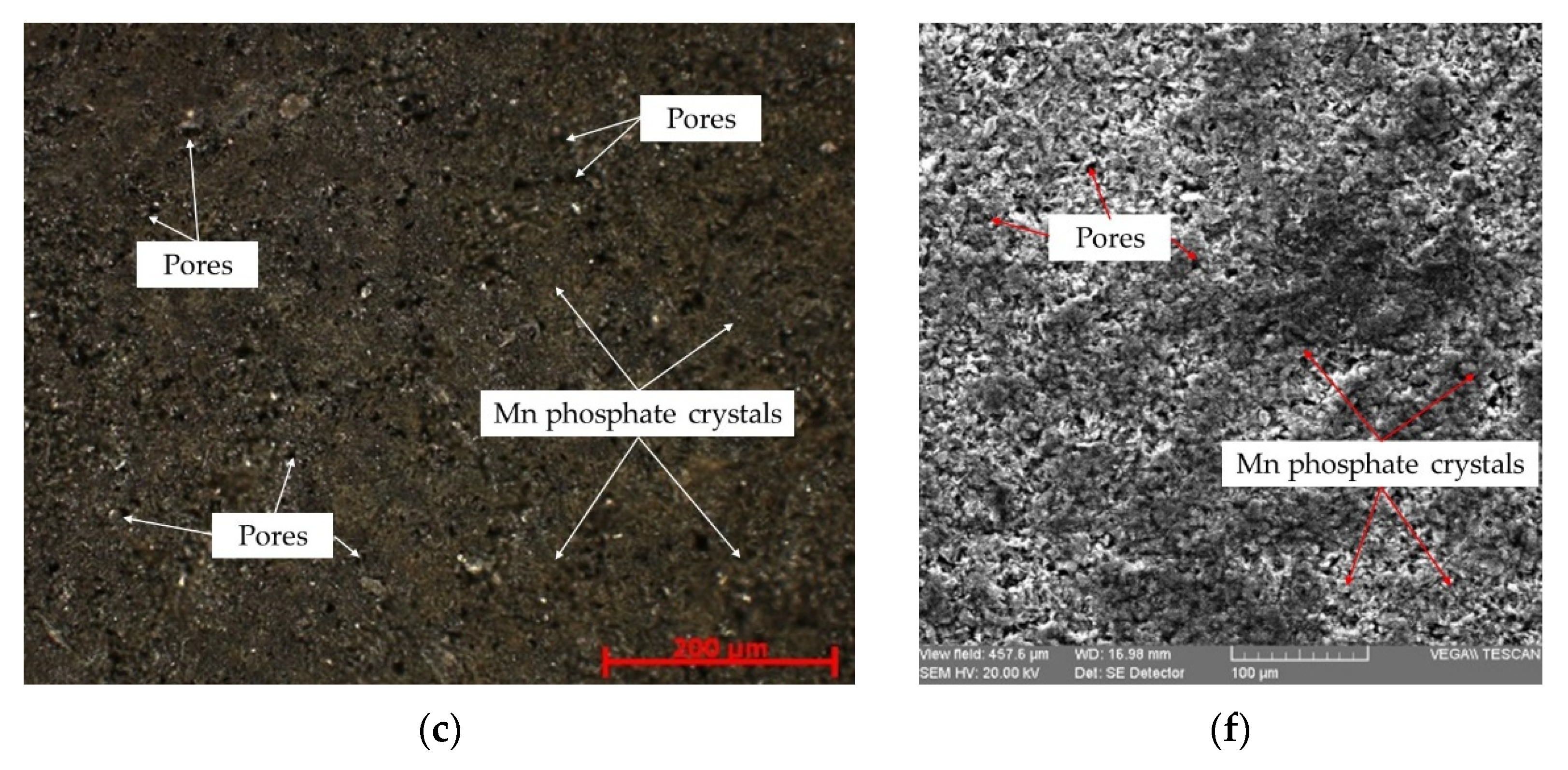
3.1. Microstructural Analysis

As can be seen from microstructural analysis, the zinc phosphate layer of the ZnPS and Zn/FePS samples was formed by zinc phosphate tetrahydrate crystals. This layer also has certain channels called intergranular regions, which provide specific porosity characteristics. The phosphate crystals on the surface of the steel are dense, resembling a flower or flakes, and this shape is specific to hopeite. The surface structure of the base metal influences the orientation of the phosphate crystals, thus determining the structure of the phosphate layer obtained. The main difference between the two samples is the size of the phosphate crystals. The addition of iron to the phosphating solution (Zn/FePS) reduced the zinc phosphate tetrahydrate crystals (Figure 3b,e), while the layer of the ZnPS sample has larger crystals (Figure 3a,d).
Compared to the zinc phosphate and zinc/iron phosphate layers, the manganese phosphate layer has a different morphology (Figure 3c,f). The crystals corresponding to zinc phosphate are larger than those of manganese phosphate. The small crystals and porous structures formed on the steel surface are unique to manganese phosphate. Due to nickel and iron addition in the manganese phosphate solution, the size of the phosphate crystals is reduced; therefore, at the microscopic level, the crystals overlap, resulting in a large uniform coating. This change in the phosphate layer can be attributed to the accelerating effect of the galvanic couple formed between Fe and Ni ions. Fe and Ni ions act as crystallisation centres during the formation process, and their number increases exponentially.

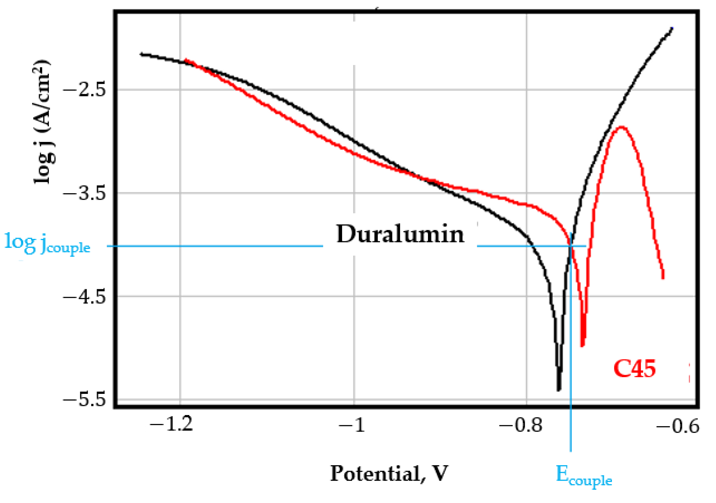
3.2. Galvanic Couples in Saltwater

The results of the study of galvanic couplings with duralumin in seawater are summarised in Table 3.
In seawater, the galvanic couplings between the studied samples and duralumin are complex, which causes the role of the anode and cathode in these couples to change. Thus, for C45, ZnPS, and LPS samples, duralumin acts as an anode and the corrosion rate of duralumin increases while the corrosion rate of the studied samples decreases. In a previous study [14] where the samples have been analysed by scanning electron microscopy (SEM) and electrochemical impedance spectroscopy (EIS), a layer of corrosion products was observed on the surface of the zinc phosphate sample exposed to saltwater. Additionally, compared with the Zn/FePS and MnPS, the zinc phosphate layer (ZnPS) exhibited the best corrosion protection.
In the case of galvanic coupling between duralumin and Zn/FePS or MnPS, duralumin plays the role of the cathode and the corrosion rate of phosphate samples increases. One of the main reasons why the Zn/FePS and MnPS are the more electronegatively alloy is the porosity of the deposited layer (Figure 3).
The galvanic coupling between ZnPS and Duralumin is presented in Figure 4a.
Aluminium bronze is a nobler alloy than duralumin, in the seawater, galvanic series is located almost towards the middle of the series, above aluminium and steel. As a consequence, aluminium bronze represents the nobler alloy and produces an increase in the corrosion rate of the studied samples with which it is coupled. The polarisation curves for the galvanic coupling ZnPS-Aluminium bronze are presented in Figure 4b. The results of the study of galvanic couplings with aluminium bronze in seawater are shown in Table 4.
For all samples, the couple potential is shifted to more positive values and the couple current density increases appreciably. Additionally, as can be observed from the data presented in Table 4, the corrosion rate increases approximately two to three times for the samples coupled with aluminium bronze compare with the corrosion rate of the sample uncoupled.
From the point of view of the corrosion resistance, in saltwater, the samples coated with a zinc phosphate layer have the best corrosion resistance from the phosphate samples (the result is fully in line with the tests performed in previous investigations [14,15]). Additionally, as can be seen, the biggest values of the corrosion rate and corrosion potential are those of the MnPS sample, which show smaller phosphate crystals and multiple pores compared with the morphology of the other phosphate samples (Figure 3c,f).
In the case of galvanic couplings between C45 and coated samples, the results obtained are shown in Table 5.
When coupling C45 with coated samples in seawater, C45 is the nobler alloy but the electronegativity difference is relatively small so that the linear polarisation curves in semi coordinates-logarithmic are very close, for the C45-ZnPS couple they even overlap (Figure 4c), the galvanic corrosion is zero in this case. For the C45-Zn/FePS and C45-MnPS galvanic couplings, there is a slight increase in the current density and the corrosion rate, respectively, while for the C45-PPS and C45-LPS galvanic couplings there is a decrease of approximately three times in the corrosion rate.
In this case, the results can be correlated with the result obtained in the paper [14], where the immersion behaviour of C45 immersed in saltwater was analysed by EIS. The study revealed that on the surface of the sample a layer of corrosion products is formed, which acts as a shield and the corrosion rate decreases over time. That is why C45 becomes the nobler alloy when it is coupled with phosphate samples.
Regarding, the PPS sample exposed to saltwater, the corrosion resistance is very low, because the paint layer is being shortly degraded [15].
When these three couples were studied in seawater a completely different behaviour was obtained. Thus, while in the duralumin/ZnPS couple, ZnPS act as a cathode, and their protection to corrosion is improved, in the AlBz/ZnPS couple ZnPS act as anode and their corrosion resistance is reduced considerably. This behaviour is altogether normal, taking into account the fact that in galvanic series in seawater, the corrosion potential of ZnPS (Ecorr = −580 mV) lies between the corrosion potential of duralumin (Ecorr = −710 mV) and aluminum bronze (Ecorr = −264 mV). The coupling of ZnPS with C45 do not induce galvanic corrosion and the ZnPS corrosiveness in seawater is not influenced (Figure 3c).
For the C45-PPS and C45-LPS galvanic couplings, there is a decrease of approximately three times in the corrosion rate.

3.3. Galvanic Couples in Fire Extinguishing Solution

Previous studies have shown that the fire-fighting solution is a much more aggressive corrosive agent than seawater, both for C45 and for covered samples. This is not the case with galvanic corrosion, where, with some exceptions, for both duralumin and aluminium bronze galvanic couplings, there is no increase in the corrosion rate but a marked decrease.
As in the case of seawater, in fire extinguishing solution the coupling with aluminium bronze decreases the corrosion resistance of ZnPS, while duralumin galvanic couplings produce only a small increase of corrosion resistance of ZnPS sample.
In duralumin galvanic couplings, all the studied samples play the role of more electropositive alloy and duralumin is the metal that corrodes, and in aluminium bronze galvanic couplings, this one is the most electropositive alloy and the studied samples corrode.
Analysing the polarisation curves presented in Appendix A and the data from Table 6, the following observations regarding the galvanic couplings with duralumin in FES can be highlighted:
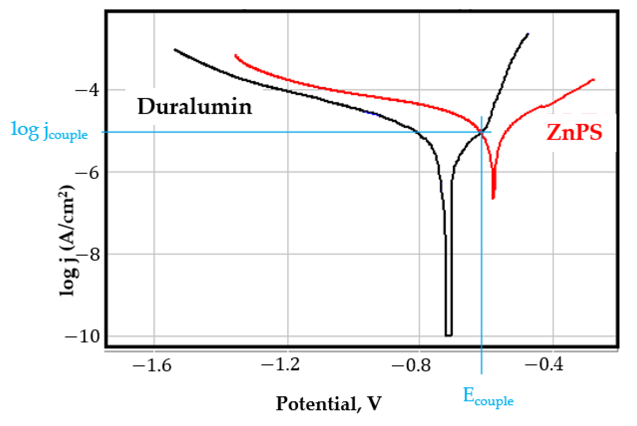
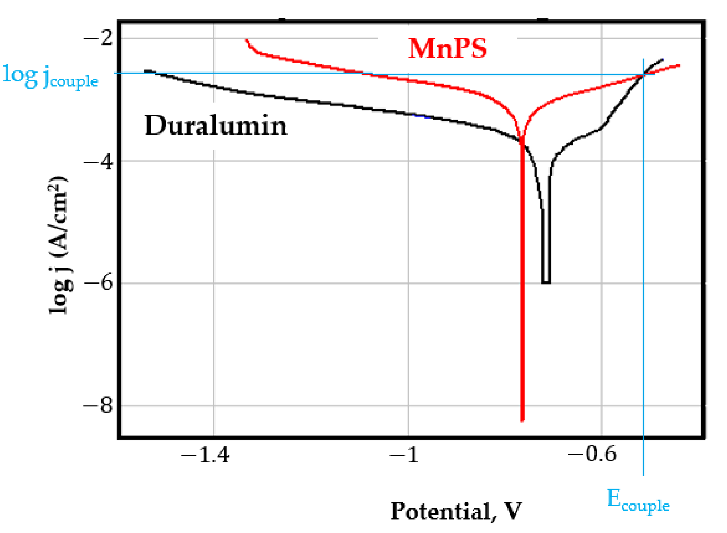
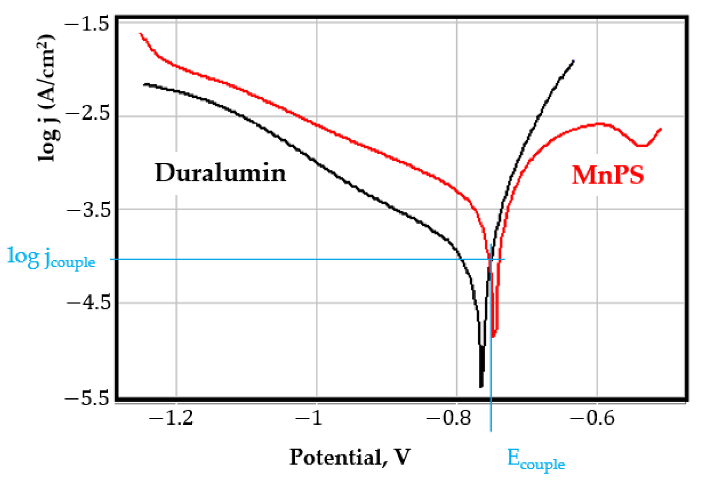
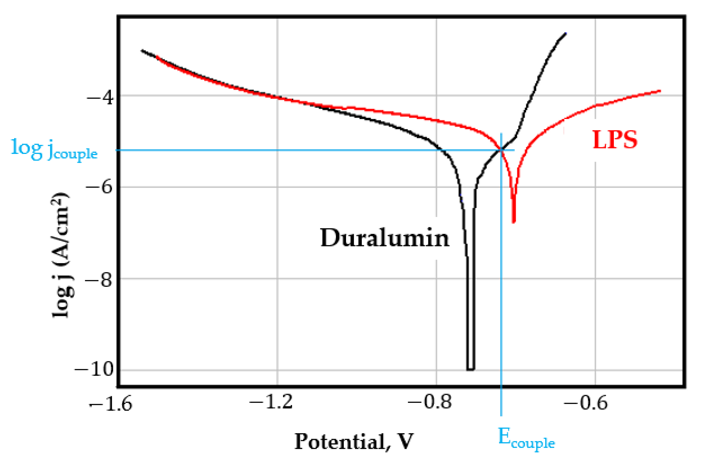
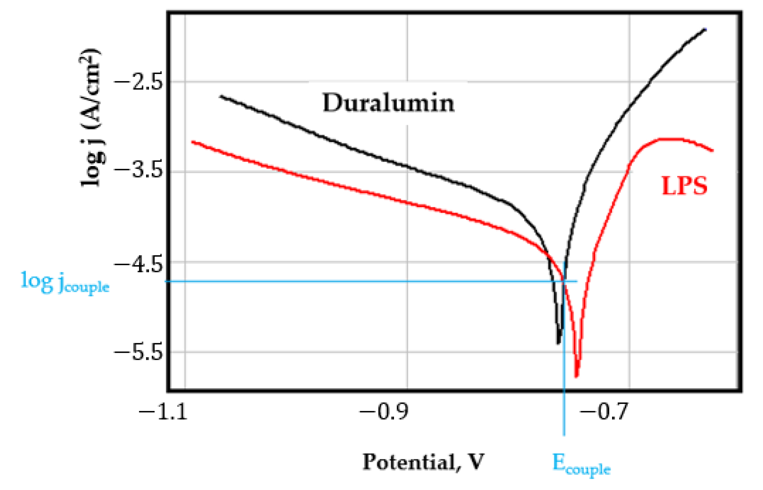
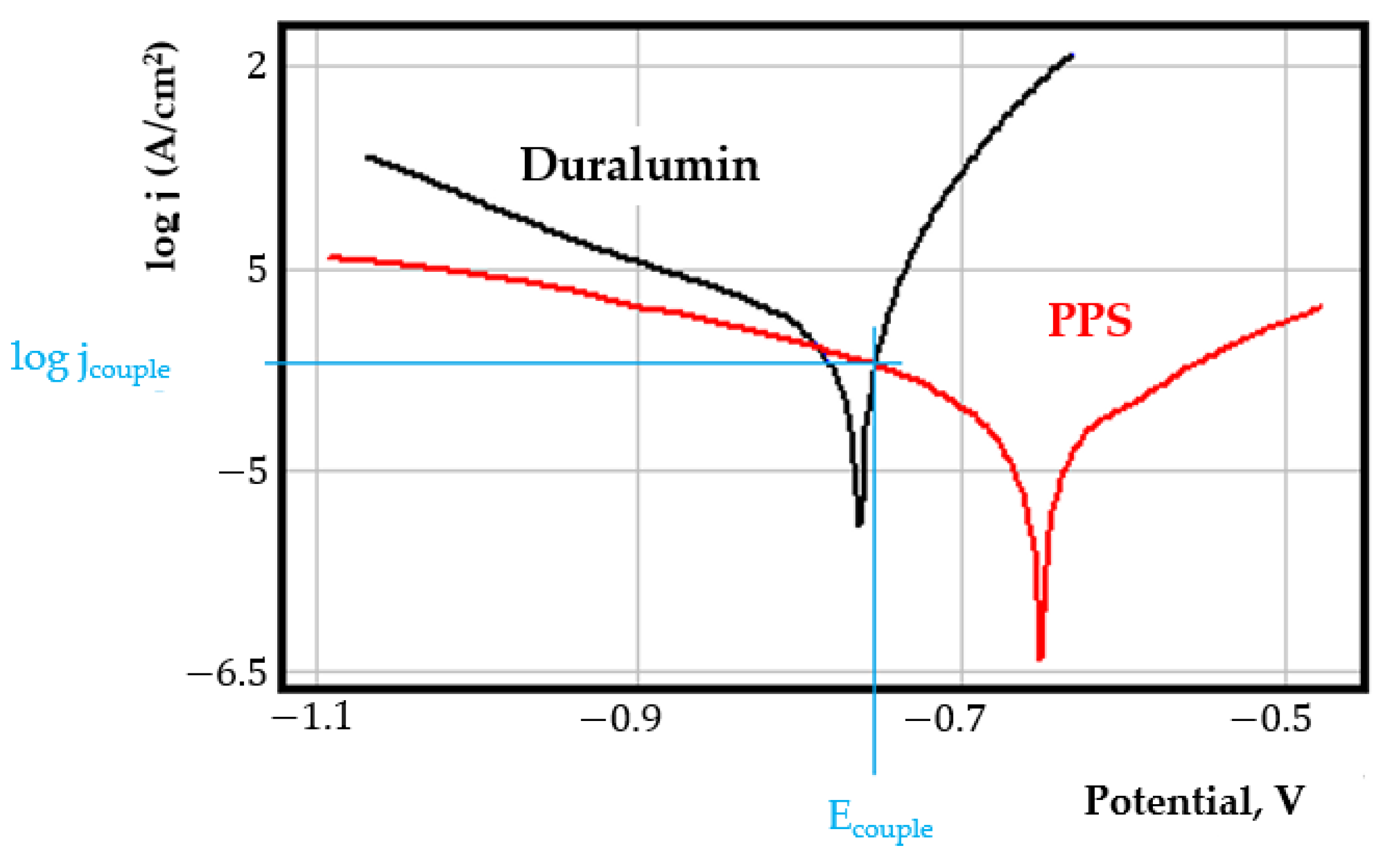
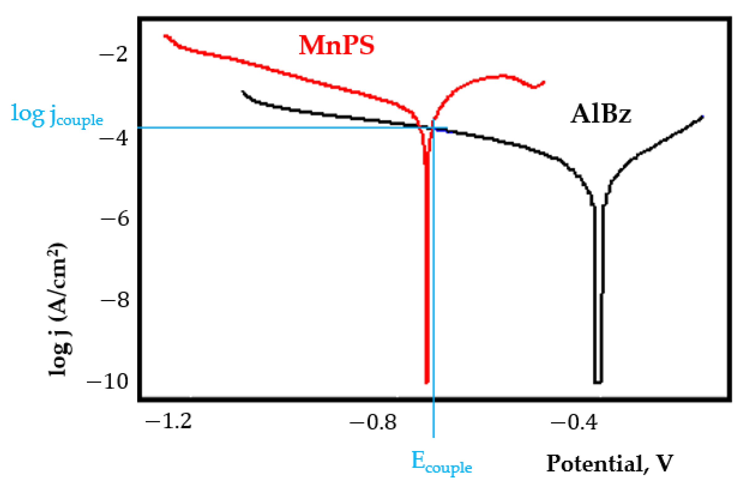
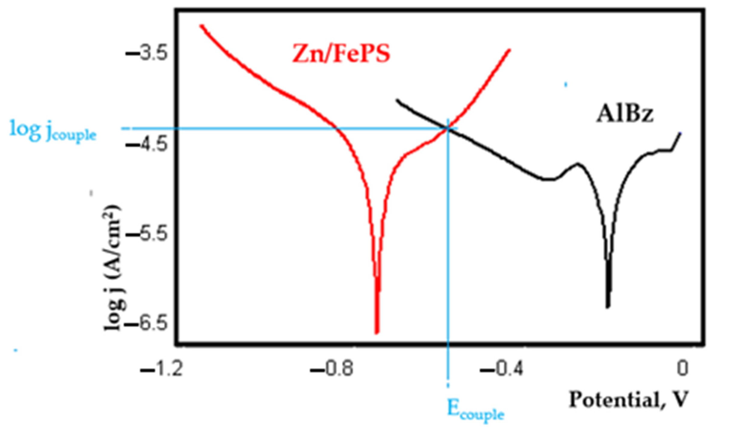
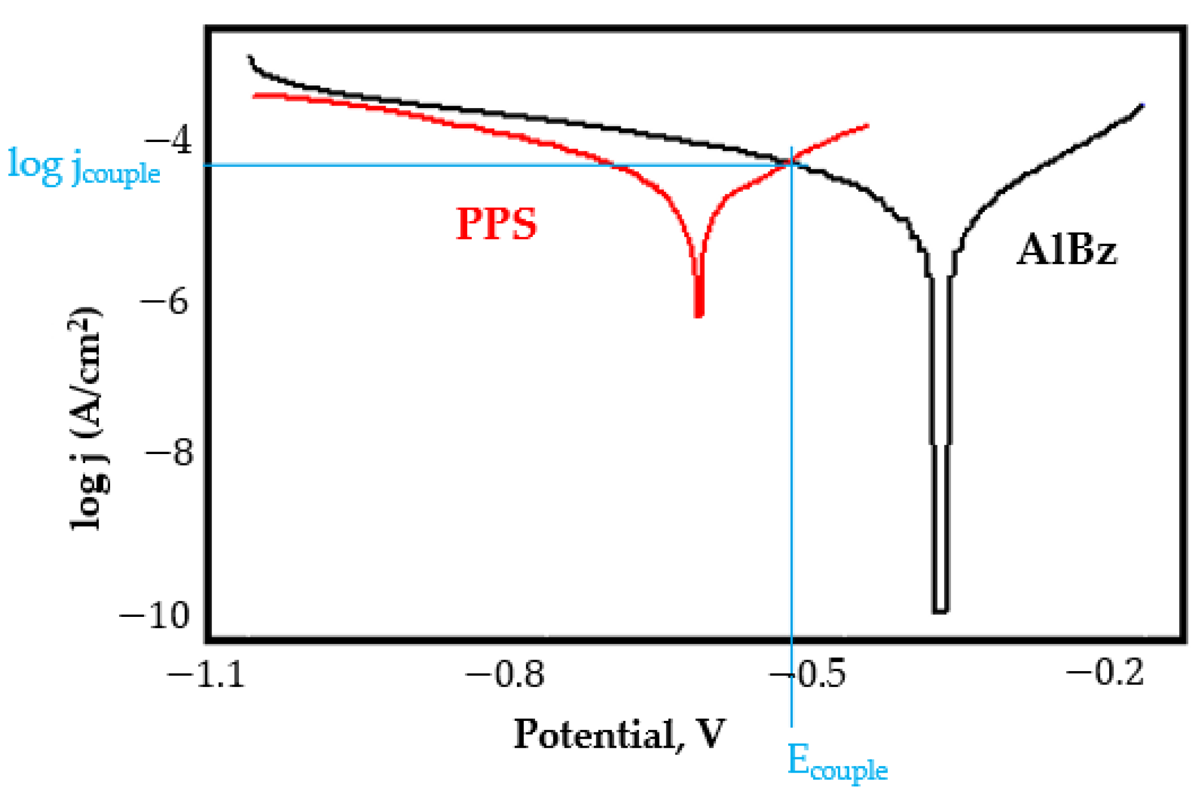
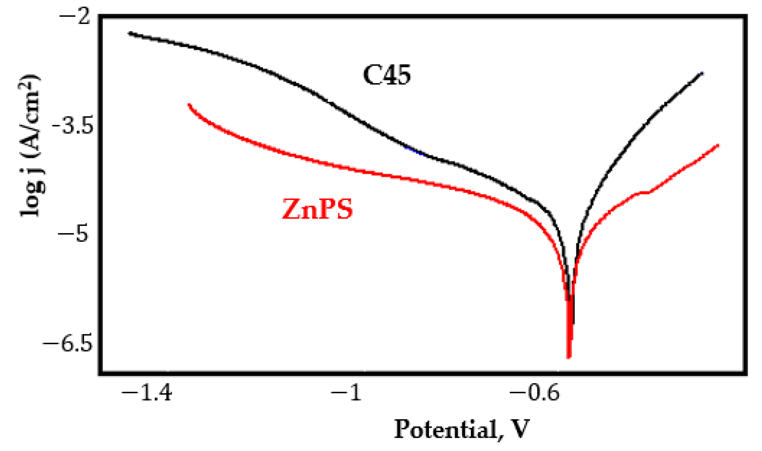
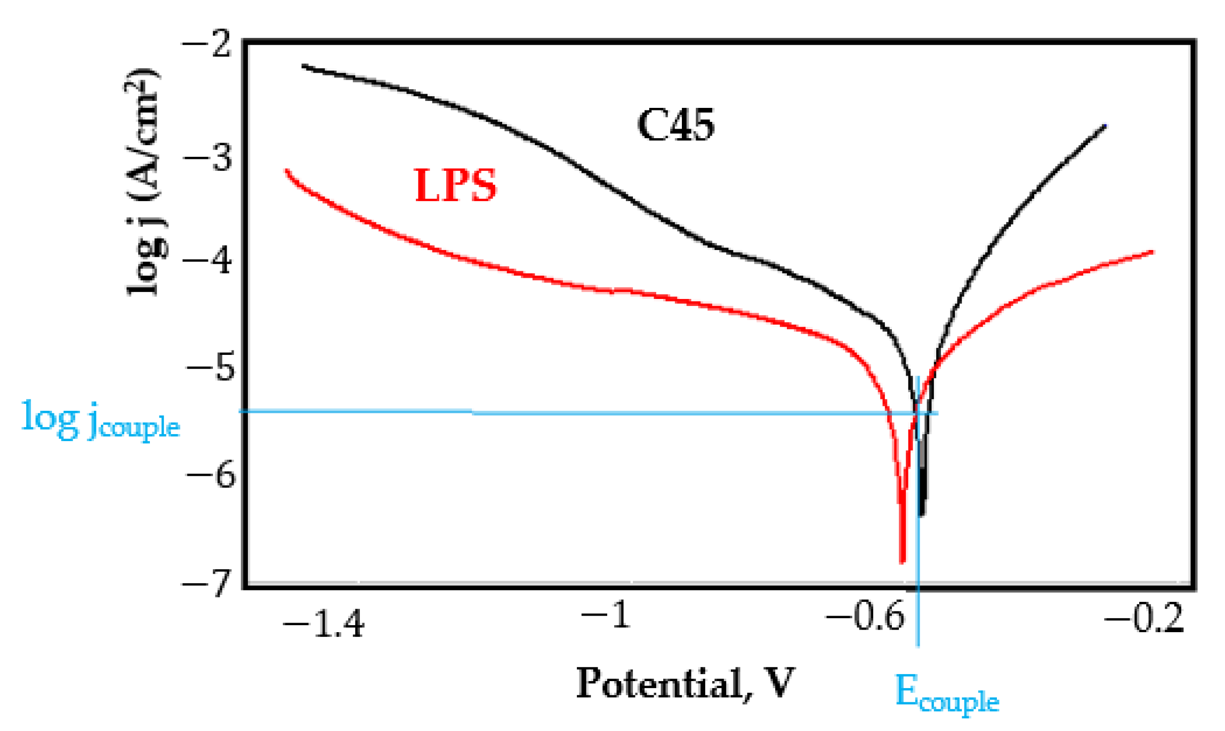
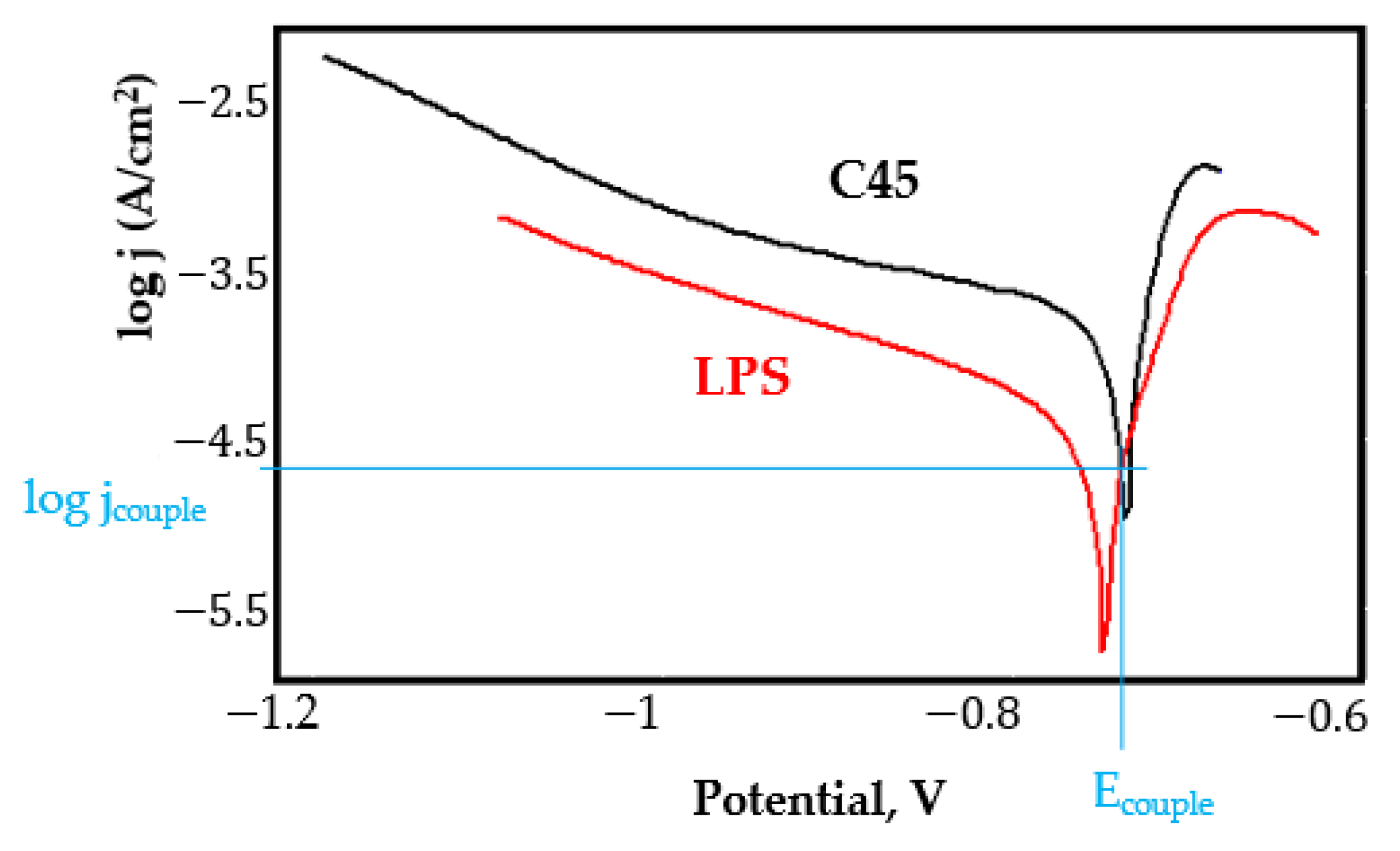
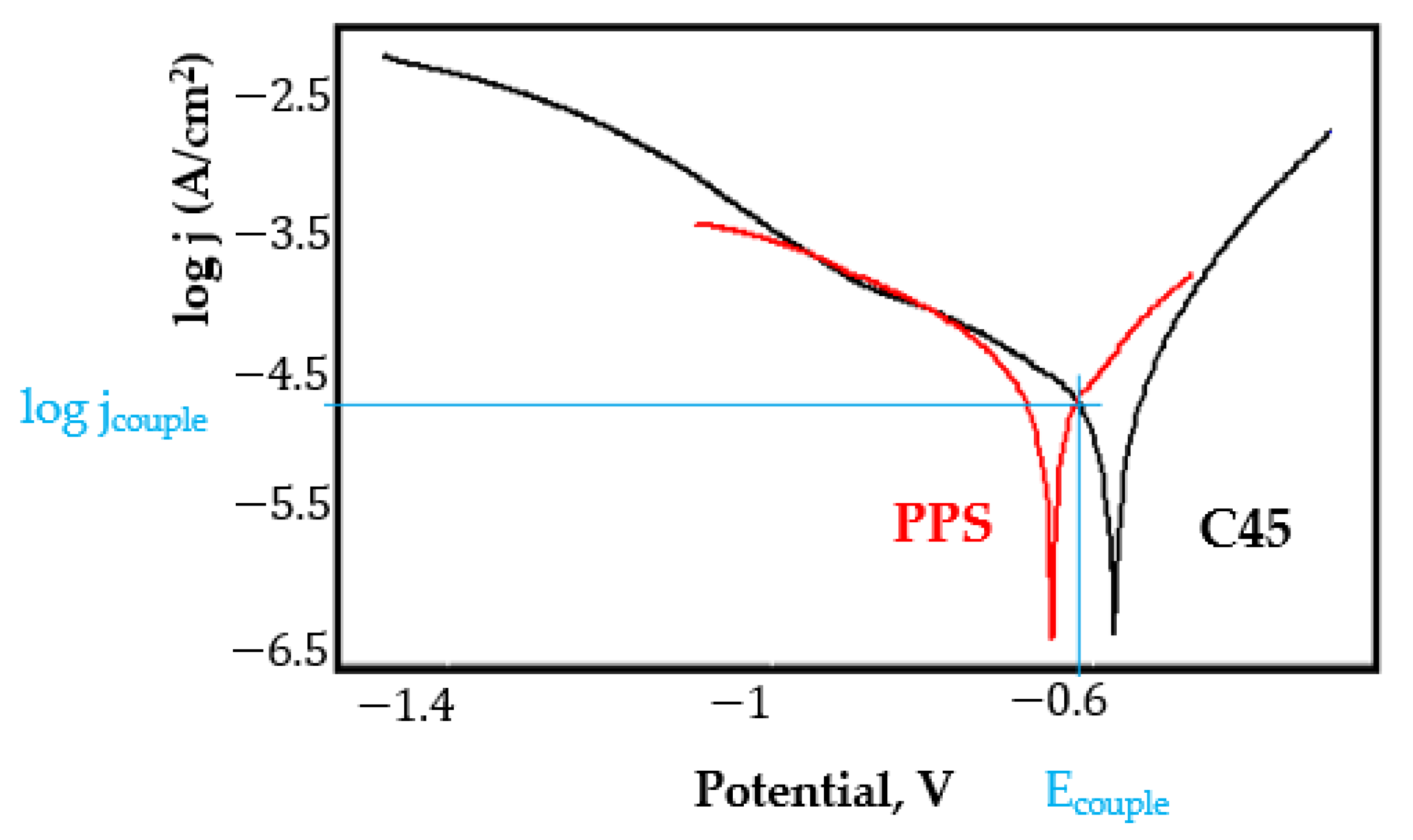
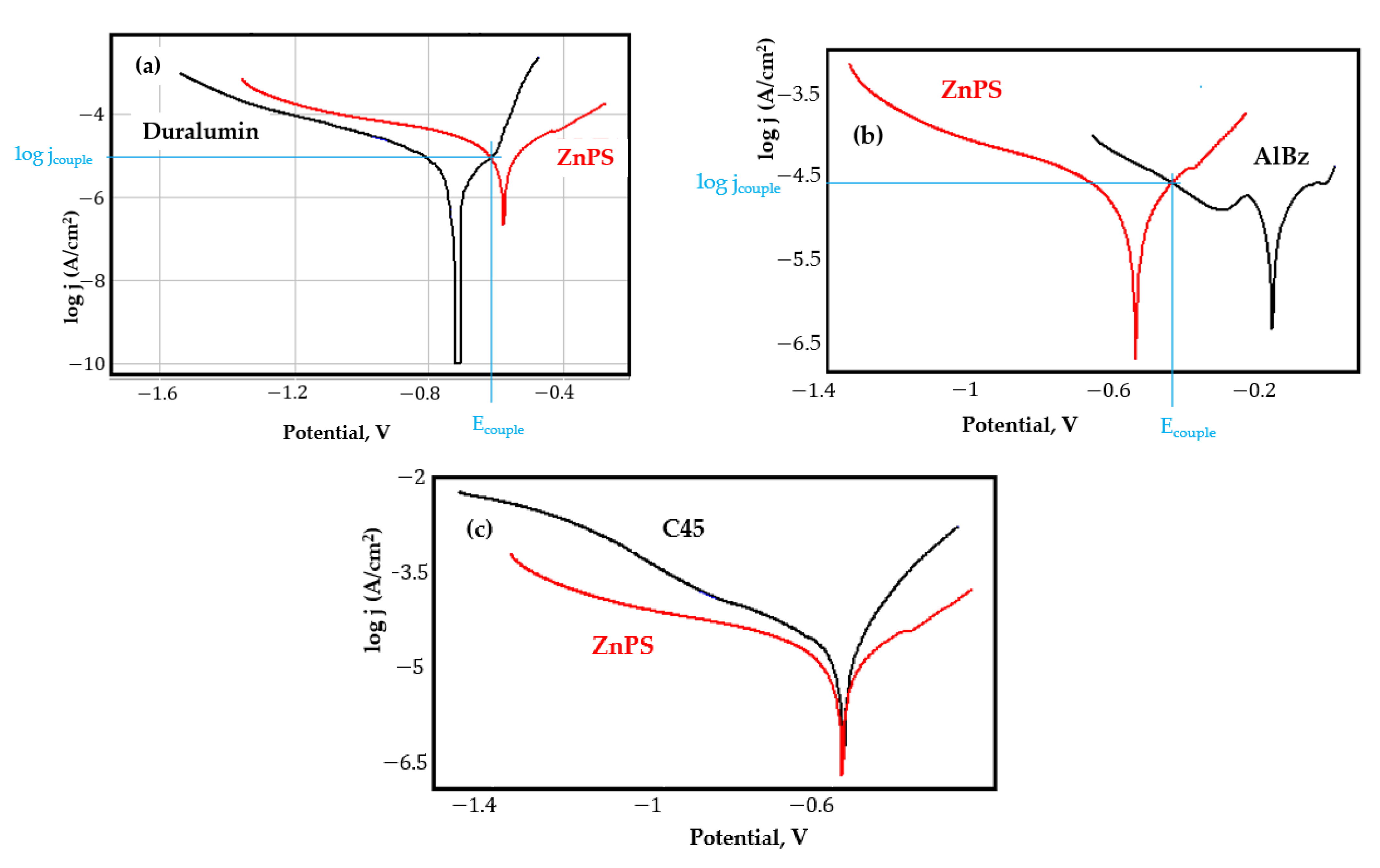
  • In the figures presented in Appendix A, the polarisation curves are very close, almost overlapping, so that the couple potential is very close to the corrosion potential of the samples, for samples C45, Zn/FePS, MnPS, and LPS, the differences being in the limit of experimental errors and only for samples ZnPS (Figure 5a) and PPS couple potential is shifted to more negative values and duralumin corrodes at a higher speed. These results can be explained by correlating with the previous study results [15]. Comparing all three phosphate samples from the point of view of the polarisation resistance, the MnPS samples has the lower corrosion resistance, while the ZnPS samples have the best corrosion resistance, due to the clogging of pores resulting in the passivation of the ZnPS sample.
  • Regarding the couple current density and therefore the corrosion rate, regardless of the value of the couple potential, the corrosion rate of C45, phosphate samples, and the lubricated sample is considerably reduced by coupling with duralumin in FES;
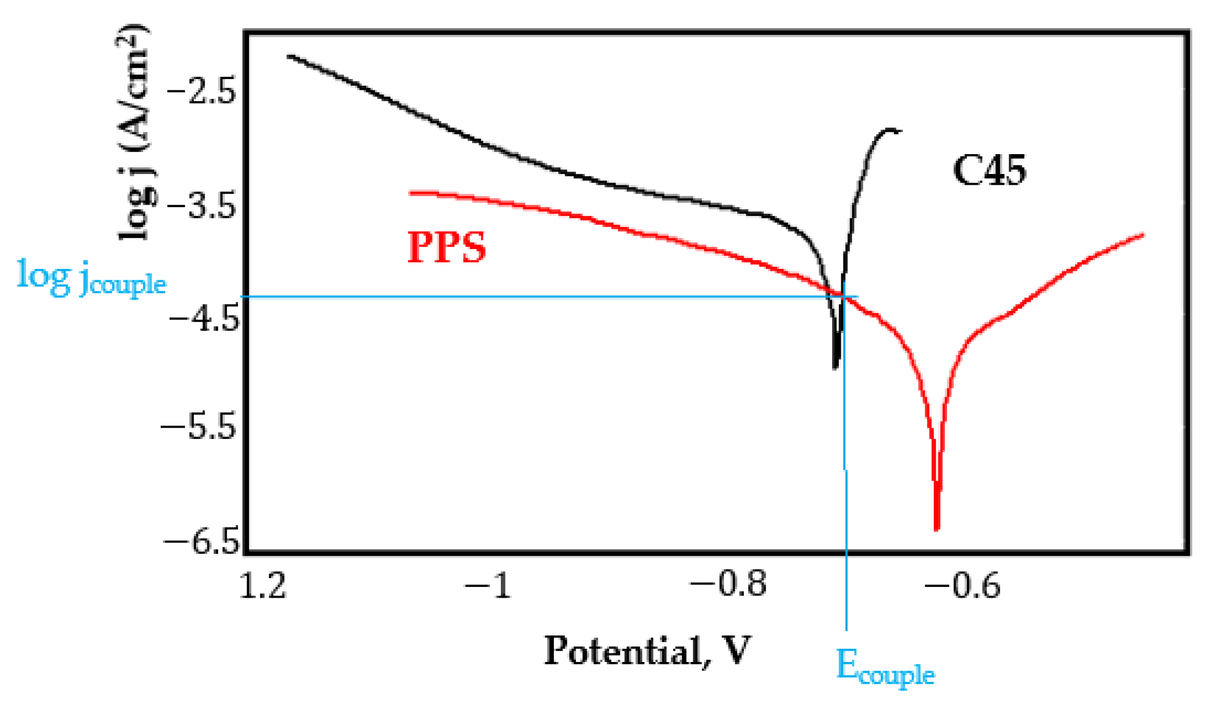
  • In the case of the painted sample by coupling with duralumin, its corrosion rate increases even if the corrosion potential is shifted to more negative values. In the EIS results were observed that the PPS sample has a lower corrosion resistance compared with the ZnPS sample, due to the fact that a layer of iron oxide was formed under the paint layer [16].
Table 7 presents the results for the galvanic couplings between studied samples and aluminium bronze alloys in FES, from which can be highlighted the following aspects:
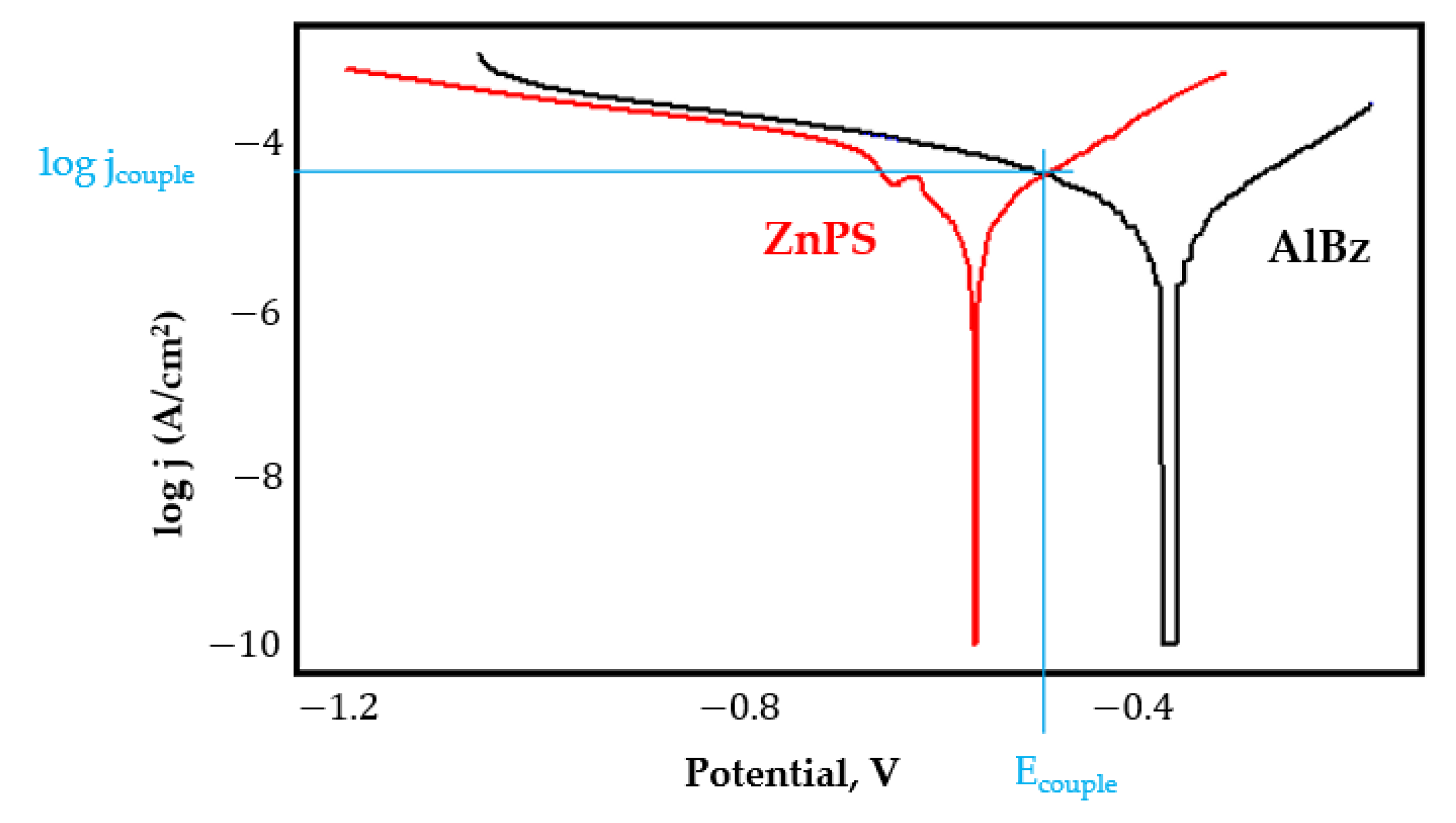
  • For all galvanic couplings the corrosion potentials are shifted relatively slightly to more positive values than the corrosion potentials of uncoupled samples;
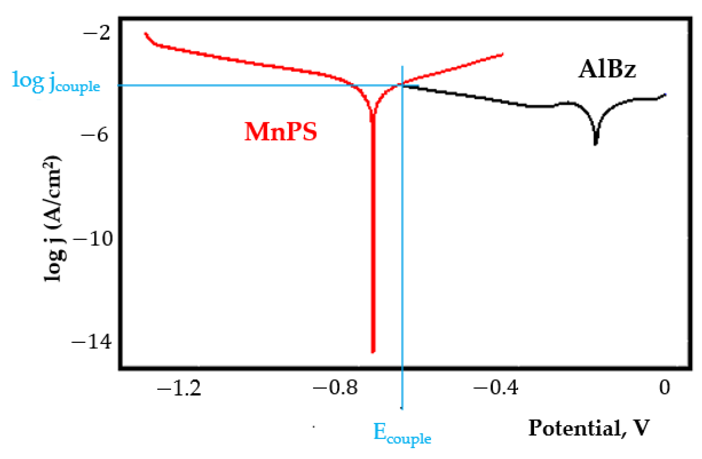
  • Although in all couples the aluminium bronze is the nobler alloy, the couple current density changes randomly, i.e., it does not change in the same direction for all couples. Thus, in the case of galvanic couplings between aluminium bronze and C45, ZnPS, and MnPS, the couple potential and corrosion rate decrease by coupling, while for couplings with Zn/FePS, LPS, and PPS the couple potential and corrosion rate increase by coupling in FES. From a qualitative point of view, this anomaly could be explained based on important changes in the surface quality of the samples in FES, which has a complex composition and has a high adsorption capacity in the pores of the coating layers. The polarisation curves for the galvanic coupling aluminium bronze/ZnPS are presented in Figure 5b.
Table 8 shows the galvanic corrosion parameters when coupling C45 with coated samples (phosphate, lubricated, and painted). The corresponding polarisation curves shown in Appendix A indicate that the polarisation curves are very close, the couple potential being slightly shifted to more positive values, except for the C45/ZnPS galvanic coupling (Figure 5c) where the couple potential is shifted quite a bit to more negative values.
The couple current density for all samples, except the painted sample, is lower highlighting passivation by coupling. In the case of the painted sample, the increase in the corrosion rate could be explained by the deterioration of the paint layer. These results are expected since, when the C45 sample surface was studied by Energy Dispersive X-Ray Analysis after immersion in FES, a layer with compounds reach in oxygen from the corrosive media (FES) mixed with small quantities of corrosion products was formed [16].

4. Conclusions

The influence of the galvanic couplings on the corrosion resistance in multiple media was reported. Accordingly, C45 sample and phosphate samples (ZnPS, Zn/Fe PS, and MnPS), as well as a lubricated sample (LPS) or painted (PPS) were coupled with duralumin and aluminium bronze in two corrosion media: seawater and fire extinguishing solution.
In saltwater the analysis of the obtained results allowed us to highlight some important observations, as follows:
  • The duralumin acts as an anode for the galvanic coupling between C45, ZnPS, and LPS with duralumin leading to a decrease in the corrosion rate of the studied samples;
  • In the case of galvanic couplings between aluminium bronze and studied sample, the aluminium bronze is the nobler alloy and acts as the cathode, leading to an increase of 2–3 times the corrosion rate of the studied samples.
In fire extinguishing solution, which is the most aggressive corrosive agent, the following conclusions can be highlighted:
  • Even if it is the most aggressive corrosive agent, the galvanic couplings with duralumin and aluminium bronze do not lead to an increase of the corrosion rate, furthermore with some exceptions the corrosion rate is decreased;
  • Similar to the galvanic corrosion behaviour in saltwater, in the galvanic couplings between duralumin and the coated sample, the latter is the more electropositive alloy and duralumin corrodes;
In the galvanic couplings between the studied samples with aluminium bronze, the last one acts as a cathode and the studied samples corrode. The coating homogeneity was evaluated by coupling the coated samples with the uncoated ones (C45). Accordingly, the following conclusions can be highlighted:
  • In saltwater, the C45 is the nobler alloy, but the electronegativity difference is relatively small (for C45/ZnPS galvanic couple the linear polarization curves overlap, galvanic corrosion, in this case, being zero).
  • In fire extinguishing solution the couple current density is lower, highlighting passivation (except for PPS sample).

Author Contributions

Conceptualisation, writing, and investigation, D.-P.B.-N.; writing—original draft, project administration, and scientific supervision, C.B.; methodology, investigation, data curation, and validation, D.-D.B.-N. All authors have read and agreed to the published version of the manuscript.

Funding

This work was supported by publications grant of the Gheorghe Asachi Technical University of Iaşi–TUIASI-Romania, project number GI/P4/2021.

Institutional Review Board Statement

Not applicable.

Informed Consent Statement

Not applicable.

Conflicts of Interest

The authors declare no conflict of interest.

Appendix A

Figure A1. The polarisation curves for galvanic coupling C45-duralumin in saltwater.
Coatings 11 01542 g0a1
Figure A2. The polarisation curves for galvanic coupling C45-duralumin in fire extinguishing solution.
Coatings 11 01542 g0a2
Figure A3. The polarisation curves for galvanic coupling ZnPS-duralumin in saltwater.
Coatings 11 01542 g0a3
Figure A4. The polarisation curves for galvanic coupling ZnPS-duralumin in fire extinguishing solution.
Coatings 11 01542 g0a4
Figure A5. The polarisation curves for galvanic coupling Zn/FePS-duralumin in saltwater.
Coatings 11 01542 g0a5
Figure A6. The polarisation curves for galvanic coupling Zn/FePS-duralumin in fire extinguishing solution.
Coatings 11 01542 g0a6
Figure A7. The polarisation curves for galvanic coupling MnPS-duralumin in saltwater.
Coatings 11 01542 g0a7
Figure A8. The polarisation curves for galvanic coupling MnPS-duralumin in fire extinguishing solution.
Coatings 11 01542 g0a8
Figure A9. The polarisation curves for galvanic coupling LPS-duralumin in saltwater.
Coatings 11 01542 g0a9
Figure A10. The polarization curves for galvanic coupling LPS-duralumin in in fire extinguishing solution.
Coatings 11 01542 g0a10
Figure A11. The polarisation curves for galvanic coupling PPS-duralumin in fire extinguishing solution.
Coatings 11 01542 g0a11
Figure A12. The polarisation curves for galvanic coupling C45-aluminium bronze in saltwater.
Coatings 11 01542 g0a12
Figure A13. The polarisation curves for galvanic coupling C45-aluminium bronze in fire extinguishing solution.
Coatings 11 01542 g0a13
Figure A14. The polarisation curves for galvanic coupling ZnPS-aluminium bronze in saltwater.
Coatings 11 01542 g0a14
Figure A15. The polarisation curves for galvanic coupling ZnPS-aluminium bronze in fire extinguishing solution.
Coatings 11 01542 g0a15
Figure A16. The polarisation curves for galvanic coupling Zn/FePS-aluminium bronze in saltwater.
Coatings 11 01542 g0a16
Figure A17. The polarisation curves for galvanic coupling Zn/FePS-aluminium bronze in fire extinguishing solution.
Coatings 11 01542 g0a17
Figure A18. The polarisation curves for galvanic coupling MnPS-aluminium bronze in saltwater.
Coatings 11 01542 g0a18
Figure A19. The polarisation curves for galvanic coupling MnPS-aluminium bronze in fire extinguishing solution.
Coatings 11 01542 g0a19
Figure A20. The polarisation curves for galvanic coupling LPS-aluminium bronze in saltwater.
Coatings 11 01542 g0a20
Figure A21. The polarisation curves for galvanic coupling LPS-aluminium bronze in fire extinguishing solution.
Coatings 11 01542 g0a21
Figure A22. The polarisation curves for galvanic coupling PPS-aluminium bronze in saltwater.
Coatings 11 01542 g0a22
Figure A23. The polarisation curves for galvanic coupling PPS-aluminium bronze in fire extinguishing solution.
Coatings 11 01542 g0a23
Figure A24. The polarisation curves for galvanic coupling ZnPS-C45 in saltwater.
Coatings 11 01542 g0a24
Figure A25. The polarisation curves for galvanic coupling ZnPS-C45 in fire extinguishing solution.
Coatings 11 01542 g0a25
Figure A26. The polarisation curves for galvanic coupling Zn/FePS-C45 in saltwater.
Coatings 11 01542 g0a26
Figure A27. The polarisation curves for galvanic coupling Zn/FePS-C45 in fire extinguishing solution.
Coatings 11 01542 g0a27
Figure A28. The polarisation curves for galvanic coupling MnPS-C45 in saltwater.
Coatings 11 01542 g0a28
Figure A29. The polarisation curves for galvanic coupling MnPS-C45 in fire extinguishing solution.
Coatings 11 01542 g0a29
Figure A30. The polarisation curves for galvanic coupling LPS-C45 in saltwater.
Coatings 11 01542 g0a30
Figure A31. The polarisation curves for galvanic coupling LPS-C45 in fire extinguishing solution.
Coatings 11 01542 g0a31
Figure A32. The polarisation curves for galvanic coupling PPS-C45 in saltwater.
Coatings 11 01542 g0a32
Figure A33. The polarisation curves for galvanic coupling PPS-C45 in fire extinguishing solution.
Coatings 11 01542 g0a33

References

  1. Bejinariu, C.; Darabont, D.C.; Baciu, E.R.; Georgescu, I.S.; Bernevig-Sava, M.A.; Baciu, C. Considerations on Applying the Method for Assessing the Level of Safety at Work. Sustainability 2017, 9, 1263. [Google Scholar] [CrossRef] [Green Version]
  2. Whitacre, D.F. Additional Techniques and Safety Hints for Climbing Tall Trees, and Some Equipment and Information Sources. Biotropica 1981, 13, 286. [Google Scholar] [CrossRef]
  3. Burduhos-Nergis, D.P.; Baciu, C.; Vizureanu, P.; Lohan, N.M.; Bejinariu, C. Materials Types and Selection for Carabiners Manufacturing: A Review. In IOP Conference Series: Materials Science and Engineering; Institute of Physics Publishing: Bristol, UK, 2019; Volume 572. [Google Scholar]
  4. Accidents at Work Statistics-Statistics Explained. Available online: https://ec.europa.eu/eurostat/statistics-explained/index.php?title=Accidents_at_work_statistics (accessed on 16 October 2021).
  5. Scott, V. Design of a Composite Carabiner for Rock Climbing; Final Report; Allen Institute for AI: London, UK, 2008. [Google Scholar]
  6. Aliha, M.R.M.; Bahmani, A.; Akhondi, S. Fracture and Fatigue Analysis for a Cracked Carabiner Using 3D Finite Element Simulations. Strength Mater. 2015, 47, 890–902. [Google Scholar] [CrossRef]
  7. Kane, B.; Ryan, H.D. Residual Strength of Carabiners Used by Tree Climbers|Request PDF. Arboric. Urban For. 2009, 35, 75–79. [Google Scholar]
  8. Lehner, S.; Senner, V. Evaluation of Ergonomics of a New Effort Saving Via-Ferrata Carabiner—Child vs. Adult Use. In Procedia Engineering; Elsevier Ltd.: Amsterdam, The Netherlands, 2013; Volume 60, pp. 319–324. [Google Scholar]
  9. Jackovics, P. Analysis with applied statistics of the safety use of rope rescue equipment. Int. J. Occup. Saf. Ergon. 2019, 26, 762–771. [Google Scholar] [CrossRef] [PubMed]
  10. Tang, H.; Qian, J.; Ji, Z.; Dai, X.; Li, Z. The Protective Effect of Magnesium Phosphate Cement on Steel Corrosion. Constr. Build. Mater. 2020, 255, 119422. [Google Scholar] [CrossRef]
  11. Fedosov, S.; Roumyantseva, V.; Konovalova, V. Phosphate Coatings as a Way to Protect Steel Reinforcement from Corrosion. MATEC Web Conf. 2019, 298, 00126. [Google Scholar] [CrossRef]
  12. Guenbour, A.; Benbachir, A.; Kacemi, A. Evaluation of the Corrosion Performance of Zinc-Phosphate-Painted Carbon Steel. Surf. Coat. Technol. 1999, 113, 36–43. [Google Scholar] [CrossRef]
  13. Teixeira, C.H.S.B.; Alvarenga, E.A.; Vasconcelos, W.L.; Lins, V.F.C. Effect of Porosity of Phosphate Coating on Corrosion Resistance of Galvanized and Phosphated Steels Part I: Measurement of Porosity of Phosphate. Mater. Corros. 2011, 62, 771–777. [Google Scholar] [CrossRef]
  14. Bejinariu, C.; Burduhos-Nergis, D.-P.; Cimpoesu, N. Immersion Behavior of Carbon Steel, Phosphate Carbon Steel and Phosphate and Painted Carbon Steel in Saltwater. Materials 2021, 14, 188. [Google Scholar] [CrossRef] [PubMed]
  15. Burduhos-Nergis, D.P.; Vizureanu, P.; Sandu, A.V.; Bejinariu, C. Evaluation of the Corrosion Resistance of Phosphate Coatings Deposited on the Surface of the Carbon Steel Used for Carabiners Manufacturing. Appl. Sci. 2020, 10, 2753. [Google Scholar] [CrossRef]
  16. Burduhos-Nergis, D.P.; Vasilescu, G.D.; Burduhos-Nergis, D.D.; Cimpoesu, R.; Bejinariu, C. Phosphate Coatings: EIS and SEM Applied to Evaluate the Corrosion Behavior of Steel in Fire Extinguishing Solution. Appl. Sci. 2021, 11, 7802. [Google Scholar] [CrossRef]
  17. Urbikain, G.; Perez, J.M.; López de Lacalle, L.N.; Andueza, A. Combination of friction drilling and form tapping processes on dissimilar materials for making nutless joints. Proc. Inst. Mech. Eng. Part B J. Eng. Manuf. 2016, 232, 1007–1020. [Google Scholar] [CrossRef]
  18. Song, G.; Johannesson, B.; Hapugoda, S.; StJohn, D. Galvanic corrosion of magnesium alloy AZ91D in contact with an aluminium alloy, steel and zinc. Corros. Sci. 2004, 46, 955–977. [Google Scholar] [CrossRef]
  19. Okonkwo, B.O.; Ming, H.; Wang, J.; Han, E.H.; Rahimi, E.; Davoodi, A.; Hosseinpour, S. A new method to determine the synergistic effects of area ratio and microstructure on the galvanic corrosion of LAS A508/309 L/308 L SS dissimilar metals weld. J. Mater. Sci. Technol. 2021, 78, 38–50. [Google Scholar] [CrossRef]
  20. Kwok, C.T.; Fong, S.L.; Cheng, F.T.; Man, H.C. Pitting and galvanic corrosion behavior of laser-welded stainless steels. J. Mater. Process. Technol. 2006, 176, 168–178. [Google Scholar] [CrossRef]
  21. Zhou, H.; Fu, F.; Dai, Z.; Qiao, Y.; Chen, J.; Liu, W. Effect of Laser Power on Microstructure and Micro-Galvanic Corrosion Behavior of a 6061-T6 Aluminum Alloy Welding Joints. Metals 2020, 11, 3. [Google Scholar] [CrossRef]
  22. Zhou, Y.; Qi, J.; Engelberg, D.L. On the application of bipolar electrochemistry for simulating galvanic corrosion behaviour of dissimilar stainless steels. Electrochem. Commun. 2021, 126, 107023. [Google Scholar] [CrossRef]
  23. Nejneru, C.; Cristina Perju, M.; Doru Burduhos Nergis, D.; Victor Sandu, A.; Bejinariu, C. Galvanic Corrosion Behaviour of Phosphate Nodular Cast Iron in Different Types of Residual Waters and Couplings. Rev. Chim. 2019, 70, 3597–3602. [Google Scholar] [CrossRef]
Figure 1. Sample shape and dimensions.
Coatings 11 01542 g001
Figure 2. Flow chart of the samples obtaining and preparation.
Coatings 11 01542 g002
Figure 3. Phosphate layer morphology: by optical microscopy 20X magnification (a) ZnPS, (b) Zn/FePS, (c) MnPS and SEM (d) ZnPS, (e) Zn/FePS, (f) MnPS.
Coatings 11 01542 g003aCoatings 11 01542 g003b
Figure 4. Polarisation curves obtained in saltwater for the galvanic couplings (a) ZnPS/duralumin, (b) ZnPS/aluminium bronze, and (c) ZnPS/C45.
Coatings 11 01542 g004
Figure 5. Polarisation curves obtained in fire extinguishing solution for the galvanic couplings (a) ZnPS/duralumin, (b) ZnPS/aluminium bronze, and (c) ZnPS/C45.
Coatings 11 01542 g005
Table 1. Description of the samples used in the experiments.
Sample IDSample Description
CSC45 carbon steel sample
ZnPSPhosphate carbon steel sample obtained using a zinc-based solution
Zn/FePSPhosphate carbon steel sample obtained using a zinc-iron based solution
MnPSPhosphate carbon steel sample obtained using a manganese-based solution
PPSZnPS sample on which a layer of elastomer-based paint was deposited
LPSZnPS sample impregnated by MoS2 based lubricant
Table 2. Chemical composition of the coupling alloys.
DuraluminAluminium Bronze
Elementwt.%Elementwt.%
Aluminium (Al)90.3Copper (Cu)82.42
Zinc (Zn)5.41Aluminium (Al)9.95
Magnesium (Mg)2.26Nickel (Ni)4.15
Copper (Cu)1.50Iron (Fe)2.13
Other elements0.53Manganese (Mn)1.35
Table 3. Galvanic couplings between the studied samples and duralumin in seawater.
SampleEcor
mV
Ecouple
mV
ΔE
mV
jcor
µA/cm2
jcouple
µA/cm2
vcor (Uncoupled)
µm/year
vcor
(Coupled)
µm/year
C45−578−600−2215.9711.99194.1135.73
ZnPS−580−615−3518.419.162223.9111.43
Zn/FePS−748−573+17515.9450.12193.8609.36
MnPS−766−517+24951.26601.1623.57311
LPS−581−637−569.386.43114.078.15
PPS−163--57.91-704.4-
Table 4. Galvanic couplings between the studied samples and aluminium bronze in seawater.
SampleEcor
mV
Ecouple
mV
ΔE
mV
jcor
µA/cm2
jcouple
µA/cm2
vcor (Uncoupled)
µm/year
vcor
(Coupled)
µm/year
C45−578−529+4915.9734.43194.1418.5
ZnPS−580−479+10118.4125.35223.9674.9
Zn/FePS−748−584+16415.9445.81193.8557.0
MnPS−766−693+7351.2695.94623.51167
LPS−581−482+999.3826.79114.0326.9
PPS−163--57.91-704.4-
Table 5. Galvanic couplings between the studied samples and C45 in seawater.
SampleEcor
mV
Ecouple
mV
ΔE
mV
jcor
µA/cm2
jcouple
µA/cm2
vcor (Uncoupled)
µm/year
vcor
(Coupled)
µm/year
ZnPS−580−580018.4118.41223.9223.9
Zn/FePS−748−644+10415.9428.18193.8342.6
MnPS−766−737+2951.2659.84623.5727.9
LPS−581−582−19.383.17114.038.52
PPS−163−619−45657.9120.46704.4248.9
Table 6. Galvanic couplings between the studied samples and duralumin in FES.
SampleEcor
mV
Ecouple
mV
ΔE
mV
jcor
µA/cm2
jcouple
µA/cm2
vcor (Uncoupled)
µm/year
vcor
(Coupled)
µm/year
C45−743−748−5183.4100.022301216
ZnPS−605−749−144146.3100.217791218
Zn/FePS−748−746+2107.948.421312588.8
MnPS−749−751−2355.477.094323936.6
LPS−752−759−742.4918.97516230.4
PPS−655−753−9820.0260.26243.4732.6
Table 7. Galvanic couplings between the studied samples and aluminium bronze in FES.
SampleEcor
mV
Ecouple
mV
ΔE
mV
jcor
µA/cm2
jcouple
µA/cm2
vcor (Uncoupled)
µm/year
vcor
(Coupled)
µm/year
C45−743−719+24183.4142.922301737
ZnPS−605−528+77146.342.271779519.8
Zn/FePS−748−716+32107.9136.113121652
MnPS−749−731+18355.4141.643231722
LPS−752−710+4242.49130.65161586
PPS−655−557+9820.0253.83243.4654.5
Table 8. Galvanic couplings between the studied samples and C45 in FES.
SampleEcor
mV
Ecouple
mV
ΔE
mV
jcor
µA/cm2
jcouple
µA/cm2
vcor (Uncoupled)
µm/year
vcor
(Coupled)
µm/year
ZnPS−605−728−123146.382.7917791006
Zn/FePS−748−738+10107.929.511312358.8
MnPS−749−740+9355.445.504323553.5
LPS−752−738+1442.4920.25516245.9
PPS−655−730+2520.0245.81243.4557.0
Publisher’s Note: MDPI stays neutral with regard to jurisdictional claims in published maps and institutional affiliations.

