Article

Resistance to Molten Superalloy at 1550 °C for Molybdenum Metal Core with a Silica/Silicide Coating

1
School of Materials Science and Engineering, University of Science and Technology of China, 72 Wenhua Road, Shenyang 110016, China
2
Institute of Metal Research, Chinese Academy of Sciences, 72 Wenhua Road, Shenyang 110016, China
*
Author to whom correspondence should be addressed.
Coatings 2021, 11(3), 275; https://doi.org/10.3390/coatings11030275
Submission received: 11 January 2021 / Revised: 26 January 2021 / Accepted: 9 February 2021 / Published: 26 February 2021

Abstract

:
This work designs a silica (SiO2) layer on a molybdenum metal core to provide new insights on the corrosion resistance of the silica/silicide coating in the Ni-based superalloy. The molybdenum substrate coated with MoSi2 by pack cementation was pre-oxidized to fabricate a cristobalite scale on the surface and the preoxidation specimens were chosen to examine the corrosion-resistant property by using a DSM11 superalloy at 1550 °C. In order to prepare a cristobalite layer, the microstructure evolution of a 40- µm MoSi2 coating with the different oxidation parameters (temperature and time) was investigated. After casting test, the different casting results showed that the silicide layer was dissolved in the molten superalloy. However, the molybdenum matrix was found to be protected by the cristobalite layer, as well as accompanied by the cristobalite layer partially destroyed at the core/superalloy interfaces. Furthermore, the reason for the destruction of cristobalite layer was analyzed. The failure mechanism of the cristobalite layer was proposed during the cast process.

1. Introduction

To increase the operation temperature of a gas turbine, ceramic-metal-composite cores have attracted more attention for their excellent properties. The specific structures can be applied to fabricate gas turbine hollow blades with designed, advanced cooling passageways. The ceramic parts are usually conventional ceramic cores, including silica ceramic cores and alumina ceramic cores, while refractory metal cores are used in metal core parts. Refractory metal cores [1] are generally composed of refractory metal (molybdenum, tungsten, tantalum, niobium, etc.) with a barrier coating. The ductile metal has better mechanical properties and can be prepared into thinner structures with new features and complex geometries. Compared with ceramic cores, refractory metal cores have advantages that favor their use in small and fine sections. Thus, refractory metal cores can be used in place of the partial ceramic core in future gas-turbine blades and vanes, such as the leading edge, the trailing edge, and the pressure side wall. That is to say that metal cores are assembled with ceramic cores to form the advanced cooling structure. Therefore, ceramic-metal-composite cores would be expected to improve the gas turbine inlet temperature.
Molybdenum (2610 °C), as a refractory metal, is suitable for the metal core. However, it is catastrophically destroyed due to the vaporization of molybdenum oxide [2] during the firing shell (T > 650 °C) and reacts with the molten superalloy during the casting process (T > 1500 °C). Therefore, the protective coatings [3] are indispensable for the application of molybdenum metal cores. After the casting to form the cavity structure, the ceramic layer can be dissolved in the KOH/NaOH solution [4], then the molybdenum substrate will be removed by utilizing the thermal oxidation (Mo→volatile MoO3) or chemical corrosion (1H2SO4 + 2HNO3 + 2H2O corrosive solution) [5].
The authors believe the silica layer can protect the molybdenum substrate during the casting process. Silicon-based cores [6,7] have been commonly used in the blade production, and the matrix material is mainly composed of silicon oxide. If silica is verified to be able to resist the superalloy, the design of the metal core coatings will be broadened. In the same sense, the alumina, silica, zirconia, magnesia, and their mixed oxides can also be used as the metal core coatings. In addition, it is well-known that the silica can be considered as an easily removed core [8,9]. Therefore, in this work, the authors will focus on the design of the silicon oxide layer onto metal cores.
Among several coatings [10,11,12] on molybdenum and its alloys, the silicide coatings [13,14,15,16] showed outstanding oxidation resistance at high temperatures due to the formation of a continuous SiO2 layer. Moreover, halide-activated pack cementation exhibits several merits—such as easy fabrication, and low cost—in these coating preparation techniques, and has been employed in various alloys in engineering application. Thus, a MoSi2 (2020 °C) coating was prepared on Mo substrate using the method in this paper, and then the SiO2 layer can be generated from the silicide layer by preoxidation.
In the present work, the 27 um, 40 um, and 63 µm MoSi2 coating oxidized at isothermal 1300 °C for 20 h were compared to observe the coating structure. The 40 µm thickness diffusion coating was a preferred thickness for the molybdenum metal core. Then, the microstructures evolution of MoSi2 coatings during the preoxidation treatment under different parameters (temperature and time) was investigated, subsequently, the corrosion-resistant property of the preoxidation specimens was tested by using DSM11 superalloy at 1550 °C. During the cast process, the corrosion resistance of the silica/silicide coating was uncovered.

2. Experiment Procedures

2.1. Prepared Coating

The pure molybdenum (99.99%) sheet with a dimensions of 24 mm × 20 mm × 0.4 mm was used as the substrate of metal cores. In order to obtain fresh surfaces, specimens were ground with SiCgrit papers from 240 # to 1000 #. They were ultrasonic-cleaned in the distilled water and ethanol, and then dried. The pack mixtures contained: 15wt % Si powder, −2 wt % NH4Cl, and −83 wt % corundum powder. The average size of silicon powder as donor sources is 500 mesh with a (99.99%) purity. The average size of corundum as an inert filler is 280 mesh with a (99.9%) purity. The NH4Cl particles as an activator have analytical reagent (AR) grade (99.5%) purity. After specimens were surrounded by uniform powders, they were putted into the horizontal tube furnace with a naturally flowing argon (40 min) to exhaust the inner air. Then, the furnace was heated up to 1100 °C for 2 h under the (0.01 MPa, 0.03 MPa, and 0.07 MPa) different pressures to prepare the (27 µm, 40 µm, and 63 µm) MoSi2 coatings. When the furnace went down to room temperature, as-coated specimens were taken off from the device. The residual powder was removed by a brush, water jet, and alcohol, and then dried. After as-coated specimens being placed into the alumina crucible, the preoxidation process was carried out in a muffle furnace.

2.2. Casting Test

The preoxidation specimens underwent a standard investment casting process. They were assembled in a wax pattern and went through several steps. The processes included slurry, stucco, dried, dewax, and fire shell, in which the ceramic shell was burned at 900 °C for 6 h. After the specimen–shell couple dwelt at 1550 °C in a vacuum induction directional solidification (DS) furnace, specimens were immersed in a superalloy melt at 1550 °C for approximately one hour, then the withdrawing rate was 6 mm/min. The experimental alloy is a Ni-based DSM11 superalloy. The nominal composition is showed in Table 1.

2.3. Characterizations

The surface and cross-sectional microstructure of specimens were observed using the field emission scanning electron microscopy (SEM, FEI Inspect F50 and FEI Apro). The SEM equipment was operated with a high voltage of 20 KeV and a spot size of 4 μm. The working distance from the specimens to the electron probe is 10.5 mm. The element component was analyzed by the energy dispersive spectroscopy (EDS) detector of Oxford Instruments. X-ray diffraction (XRD, D/Max 2500PC) with a Cu target was performed to identify the phase composition. The Kα radiation generated at an acceleration voltage of 45 kV and a current of 200 mA. The scanning parameter was set at 2theta degrees from 20° to 80°, with a step size of 0.02° and a scanning speed of 10° min−1. The data of XRD spectrum was dealt with Jade 6 and origin 2018 software.

3. Results and Discussion

3.1. The Microstructure Evolution of As-Coated Specimens after Oxidation

As a diffusion coating, the thickness is highly correlated with service life. Figure 1a shows the thickness change of the (A—27 µm, B—40 µm, C—63 µm) coatings at isothermal 1300 °C for 20 h. After oxidation, the total thickness of the A-coating is 44.78 µm (Ⅰ 3.99 µm SiO2, Ⅲ 36.12 µm Mo5Si3, Ⅳ 4.67 µm Mo3Si); B-coating is 72.2 µm (Ⅰ 4.02 µm SiO2, Ⅱ 21.01 µm MoSi2, Ⅲ 47.17 µm Mo5Si3) and C-coating is 91.61 µm (Ⅰ 4.2 µm SiO2, Ⅱ 45.38 µm MoSi2, Ⅲ 42.03 µm Mo5Si3). For the A-coating, it is obvious that the formation of Mo3Si and the disappearance of MoSi2 are due to the high-temperature diffusion of silicon. In the wake of the entire degeneration from MoSi2 to low-silicon silicide (Mo5Si3, Mo3Si), MoSi3 phase will grow in the Mo5Si3/Mo diffusion couple and no other new phases are formed in the diffusion coating [17]. In spite of low-silicon silicide (Mo5Si3 (2180 °C), Mo3Si (2023 °C)) having a high melting point, low-silicon silicide with a low resistance to oxygen will accelerate the failure of the coating [18]. However, the thickness of Mo3Si in the B- and C- coatings is so small and uncritical that it can be neglected. The coating is mainly composed of SiO2, MoSi2 and Mo5Si3 after oxidation. Therefore, the phase component and thickness of the coating varies with the augmentation of original MoSi2 thickness. In addition, the development of coating structure can be inferred according to the phase component and thickness of the coating. The high silicon of MoSi2 results in the main growth of Mo5Si3. Meanwhile, the growth rate of Mo5Si3 is greater than that of Mo3Si at the initial stage of the diffusion process. When the depletion of MoSi2 is up to a certain extent, the growth rate of Mo3Si has priority over Mo5Si3 and the formation of coating is dominated by Mo3Si. Based on the above analyses, these results suggest that the MoSi2 thickness has an important effect on the service life of the coating and the conversion of coating structure. In view of the MoSi2 being brittle at low temperatures (T < 1000 °C), the total thickness of coating should be as thin as possible. For the peroxidation, 40 µm is selected as an appropriate thickness.
After oxidation, a typical cross-sectional BSE image of specimens at 1300 °C for 10 h is presented in Figure 1c. The whole coating is relatively uniform and dense. Due to different diffusion coefficients of Mo and Si [17], the mutual diffusion results in the formation of Kirkendall effect pores shown in red arrows. In addition, a few cracks (white arrows) are generated as a result of thermal expansion coefficient (CET) mismatch (MoSi2, 8.2 × 10⁻⁶ K−1; Mo, 5.8 × 10⁻⁶ K−1) during the cooling from the oxidation temperature to room temperature. According to EDS analysis (Table 2. spot1, 2, 3, 4) and XRD pattern (Figure 1b), the multilayer structure is composed of 2.92 µm SiO2, 20.29 µm MoSi2, and 33.13 µm Mo5Si3. The SiO2 layer forms on the surface of specimens as a result of the oxidation reactions [19]. The oxidation reactions are described as the follows:
MoSi2 + 7/2O2 = MoO3 + 2SiO2.
MoSi2 + 7/5O2 = 1/5Mo5Si3 + 7/5SiO2.
Mo5Si3 + 2 1/2O2 = 5MoO3 + 3SiO2.
The formation of silica restrains the oxygen diffusion and reduces the oxygen partial pressure between SiO2 and Mo5Si3. Beneath the SiO2 layer, the white Mo5Si3 layer with low silicon is different from the Mo5Si3 phase with high silicon at the interface of MoSi2 and Mo. The former is formed by the consumption of silicon, inducing to form the growth of the low-silicon-structure Mo5Si3, and the low-silicon-structure is well-kept by the rapid diffusion of the silicon [20]. The latter can be attributed to higher silicon diffusion potential that leads to the degradation of MoSi2 into Mo5Si3 [17]. Moreover, the Mo5Si3 phase also distributes across the MoSi2 interlayer in the green arrows of Figure 1c, which implies that the degeneration of MoSi2 occurs both internally and externally.
From the cross-sectional coating structure, the silicide, by consuming itself, forms the silicon oxide to protect the Mo substrate, whereas silicon dioxide has a variety of crystalline forms, such as cristobalite, quartz glass, quartz, etc. Figure 2 shows the crystal structure change of silicon dioxide under different conditions. Considering that the sintering temperature of silicon-based core is about 1200 °C to control the transformation from the quartz glass to cristobalite, the high temperature (T > 1470 °C) further increases the content of cristobalite in the (DS) furnace. Thus, the cristobalite is expected to be the structure lattice that will protect the molybdenum core in the superalloy.
Figure 3a shows the surface morphology of specimens heated at 1100 °C for 2 h. Quite a few white particles are embedded in the surface. EDS (Table 2 spot5) reveals that the white particles are molybdenum oxide that have been incompletely oxidized. The uneven surface is due to abrasive paper scratches and the relatively thin oxide film. After the coating is oxidized at 1200 °C for 2 h, shown in Figure 3b, it is observed that the white particles (Table 2 spot6) reduce on the outside surface and the morphology of SiO2 presents the package structure. Corresponding XRD patterns (Figure 1b) indicate that the package structure SiO2 is cristobalite. When temperature remains at 1300 °C for 2 h (Figure 3c) and 10 h (Figure 3d), the white particles have vanished in virtue of the transformation into volatile molybdenum oxide. Moreover, the morphology of silica also keeps a package structure and some microcracks emerge on the surface. The cracks formed on the cristobalite layer are due to the CET mismatch between cristobalite (10.3 × 10⁻⁶ K−1) and silicide. With further increased time to 15 h (Figure 3e), some holes appeared, but with no penetration inside the oxide layer. The formation of holes may be because the oxide layer grows outward and the poor fluidity of cristobalite cannot heal in high temperatures. According to the morphology evolution of the silica and XRD patterns (Figure 1b), the external layer is composed of the cristobalite. Therefore, the service life and oxidized structure of MoSi2 coating depends on the thickness. After oxidation at 1300 °C for 10 h, the typical structure of 40 µm MoSi2 has three main-layers: SiO2, MoSi2, and Mo5Si3. Meanwhile, the external oxide layer is the cristobalite phase in 1300 °C for above 2 h.

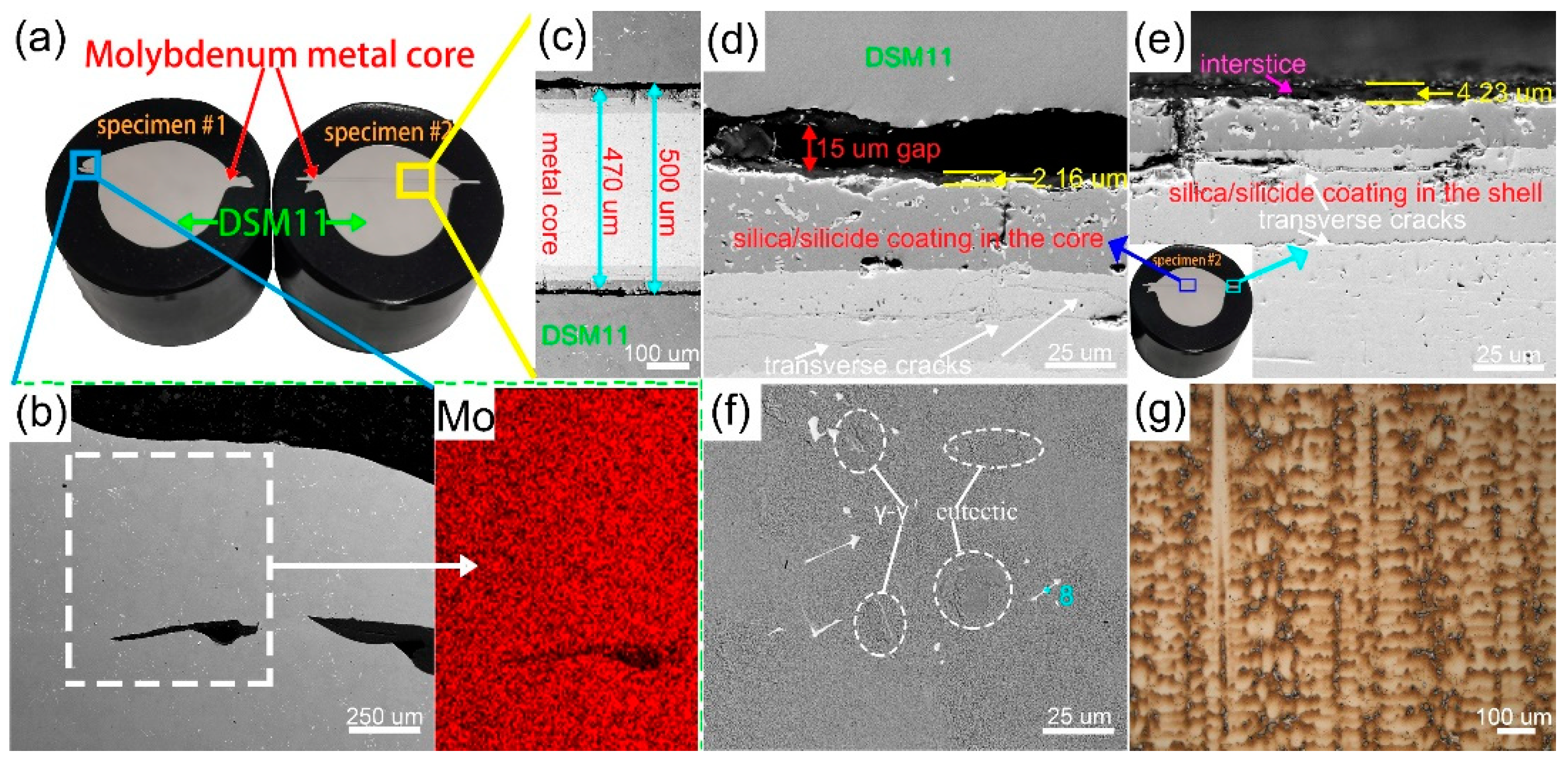
3.2. The Microstructure of As-Coated Specimens after Casting Test

Specimens at 1100 °C for 2 h (specimen #1) and at 1300 °C for 10 h (specimen #2) were selected to test the corrosion-resistant property. The macrophotograph of specimens after the casting test is shown in Figure 4a, which, respectively, contains molybdenum metal core and a DSM11 rod. The core (specimen #1 on the left) is difficult to be distinguished near the center, whose place is merely traced in the blue rectangle. The BSE image of this region is shown in the Figure 4b. Correspondingly, Mo mapping (Figure 4) indicates that there is no regional enrichment of molybdenum elements in the position of the metal core and the distribution of molybdenum elements is uniform in the ingot. It can be deduced that the molybdenum core has dissolved into the superalloy before being withdrawn. Thus, both the silicide layer and Mo matrix have been corroded in the molten alloy. The reason of the failure is presumed to be the rupture of Mo–Mo and Mo–Si bonds in the molten metal at 1550 °C.
Specimen #2 on the right (Figure 4a) shows the fine limitations between the molybdenum metal core and superalloy. The cross-sectional BSE image, as shown in Figure 4c (5 g CuSO4 + 25 mL HCl + 50 mL H2O etch, etching time 10 s), indicates that the silica/silicide coatings are confirmed to protect the molybdenum metal core. Compared to the front result, it is attributed to the cristobalite, which plays a decisive role in protecting the metal core. The cristobalite has a more stable structure than the silicide in superalloy. The metal core has approximately 470-µm total thickness with a 500-µm cavity. As Mo substrate thickness decreases, a thinner cooling structure can be fabricated by metal core. Figure 4d shows the high-magnification BSE image of this region. There is a 15-µm gap between the cristobalite layer and DSM11. The formation is due to the cooling shrinkage (Mo, 5.8 × 10⁻⁶ K−1 and DSM11, 12.2 × 10⁻⁶ K−1). Moreover, the surface wettability may have some influence on the interface interval [21]. In the silica/silicide coating, some transverse cracks are observed in the white arrows of Figure 4d. The cracks result from the pressure stress that comes from the thermal shock of alloy melt. Figure 4e shows the BSE image of the partial core in the shell position. The coating also comprises similar multilayers including the pores and cracks. The interstice between SiO2 and silicide is obviously observed and the presence of interstice reflects that the interface force is fragile. The main reason is presumed to be that the CET (10.3 × 10⁻⁶ K−1) of cristobalite is higher than Mo5Si3 [22]. Moreover, the SiO2 layer in the DSM11 (2.16 µm) and shell (4.23 µm) have different thicknesses, which is explained later. Figure 4f shows a typical BSE image of DSM11 alloy. γ′, γ/γ′ eutectic and white irregular-shaped phases spread in cast alloy. EDS analysis (Table 2 spot9) indicates that precipitated phases mainly contain C, Ti, Ta and W elements. According to researches on the microstructure of the cast alloy [23,24], the phase is confirmed to be MC carbides. Thus, the microstructure has no other phase apart from γ′, γ/γ′ eutectic and MC carbide in γ matrix. Figure 4g shows the cross-sectional OM image (specimens2#, 5 g CuSO4 + 25 mL HCl + 50 mL H2O etch, etching time 10 s). The longitudinal dendrite is relatively fine with roughly the same orientation <001>. The core has no distinct effect on the directional grow process. Therefore, the above results reveal the different function of the silica/silicide coating. The silicide coating with high melt point merely protects the Mo matrix from being oxidized and generates a silica layer in the static air. Nonetheless, the cristobalite layer can protect the molybdenum metal core in DSM11 superalloy at 1550 °C. Meanwhile, the cooling shrinkage gives rise to a 15-µm gap during the solidification stage. In addition, there is no presence of an Si-rich phase in the DSM11 alloy and the growth orientation of primary dendrite is not affected by the molybdenum metal core.

3.3. Interfacial Microstructure between Superalloy and Core

The gaps (Figure 4c,d) show that the core has no contact with the DS alloy. Thus, the sample #2 can be separated into two parts to analyze the interfacial surface. Figure 5a shows the BSE image of metal cores in the DSM11. A discontinuous SiO2 layer covers the surface of the sample, and the bare silicide matrix (Table 2 spot 9) can be observed in the white arrows. In addition, the block cristobalite is adhered to the outside surface. The magnified red rectangle of local region is shown in the bottom-left SEM image of Figure 5a. The surface microstructure suggests that the formation of fracture pattern is torn by the casted part [25]. Thus, the cristobalite layer has been partially destroyed. Figure 5b shows the surface SEM image of the core in the shell. The cristobalite layer remains relatively intact and the package structure of silica can be clearly seen. A few interfacial reaction products exist on the surface. EDS (Table 2 spot10) suggests that white products include Al and Cr elements. The reactions between active elements (Al, Cr) and SiO2 have been reported in the previous studies [26,27,28]. Thus, the cristobalite reacts with the active element (Al, Cr) of the alloy in the cast process. The reactions can be written as follows:
Al+3/4SiO2→1/2Al2O3 +3/4Si.
Cr+3/4 SiO2→1/2Cr2O3 +3/4Si.
By comparing the metal core in the alloy and shell, the interfacial reactions also occur in the metal core in the DSM11 position, and are more serious. The destroyed silica layer has resulted in the different thicknesses (Fig4d and e). Figure 5d shows the DSM11 superalloy surface covered with the silica, which is also confirmed by XRD pattern (Figure 5c). The enlarged magnification BSE image of the rectangle in Figure 5d is shown in Figure 5e. The elementary mappings (Si, Al, O, Ni, Cr, Ti, and Mo) reveal that the light color zone is the Ni-based alloy matrix and the silica layer is mixed with the Al, Ti, Cr, Ni elements. Mo mapping (Figure 5) indicates the white spot of the surface (Figure 5e) should be rich-Mo silicide. Therefore, a thin silicon oxide film mingling with the alloy element is attached to the DSM11 surface and the serious interfacial reactions between the alloy and cores at the temperature of about 1550 °C is demonstrated again.
Combined with the above analysis, it can be concluded that there are several reasons behind the destroyed cristobalite layer during the cast process. Firstly, as a ceramic material, the silica has poor strength, further, the cristobalite layer contains microcracks, which decrease the strength of the silica. Especially, the ceramic layer is entirely composed of the cristobalite. Previous research [4] has also revealed that the flexural strength decreases with the increase of cristobalite content in the silica-based core. Meanwhile, the transition of α-β phase generates microcracks in the ceramic cores [4] and the generated microcracks are often the source of cracks when fractures are propagated. The law in the silica-based core is analogue with the cristobalite layer. Secondly, the adhesive force between the cristobalite layer and silicide layer is relatively weak as a result of the CET mismatch. Finally, the interaction between the cristobalite and DSM11 alloy at 1550 °C makes the layer partially destroyed. Besides, we speculate the source of rupture should be close to the silicide coating. Due to the transition of the α-β phase accompanied by volume change and the relatively poor adhesive force due to the different CET between cristobalite layer and silicide layer, it will be prone to generate more microcracks near the silicide layer. The destroyed cristobalite layer (Figure 5a) presented a discontinuous SiO2 layer with the bare silicide matrix.
The interaction between the cristobalite and DSM11 alloy during the cast process is described in Figure 6. Firstly, the active elements (Al, Cr) react with SiO2 to form an interfacial layer. Other elements Ni, Ti etc, together diffuse into the reaction layer. Owing to the operating temperature of the silicon base core generally being lower than 1550 °C, the excessively high pouring temperature further accelerates the interface reactions [27]. Then, severe interface reactions produce an interface bonding, consequently, the cristobalite is attached to the surface of the cast part. Afterwards, rods are slowly withdrawn from the heating chamber to force the directional growth. The temperature goes down and the liquid becomes the directional alloy. The CET of the DSM11 and cores triggers the volume shrinkage and the contraction tension is greater than the interaction force of cristobalite. As the solidified shrinkage gradually increases, the tension tears the cristobalite layer.

4. Conclusions

From this article, the main conclusions are summarized as follows:
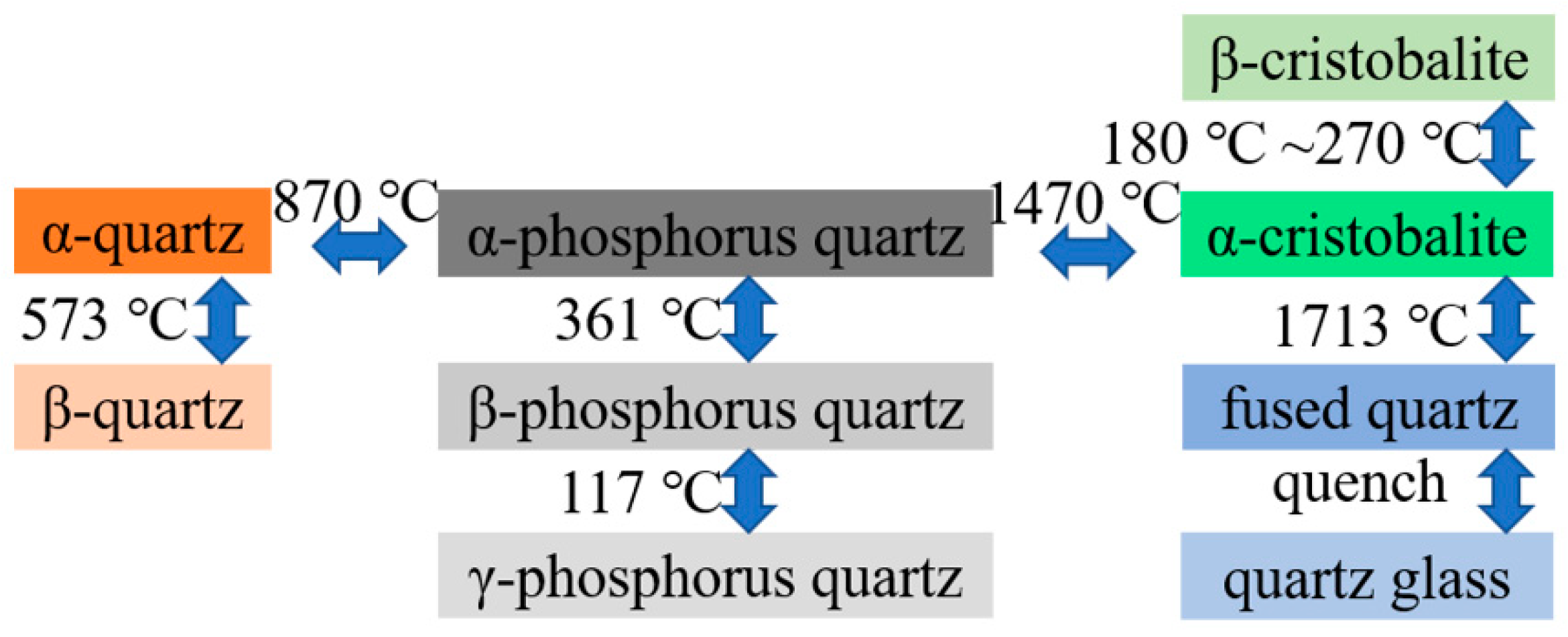
  • The service life and oxidized coating structure rely on the MoSi2 thickness. After oxidation, the 40-µm MoSi2 structure is composed of SiO2, MoSi2, and Mo5Si3 at 1300 °C for 10 h. Meanwhile, the silica formed on the surface is cristobalite at 1300 °C for above 2 h.
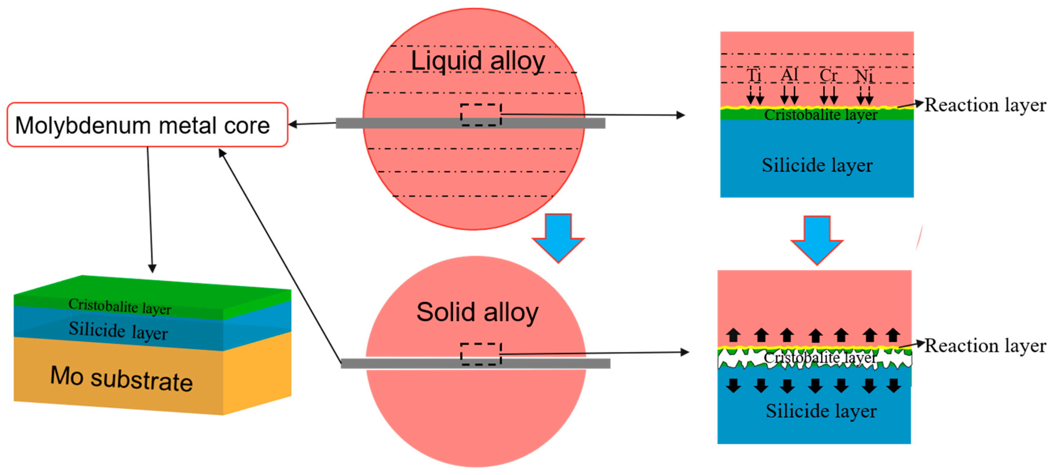
  • The silicide coating and Mo metal are dissolved in the alloy, whereas the cristobalite layer prevents the alloy from entering the substrate. By contrast, the primary function of intermetallic compound coating can offer the oxidation-resistant abilities and the cristobalite layer plays an important role in resisting the corrosion of superalloy.
  • Although the cristobalite layer protects the molybdenum metal core, this layer was destroyed during the casting test. Furthermore, the Si-rich phase is not formed in the DSM11 alloy and growth orientation is not affected by the molybdenum core. In addition, the formation of a 15-µm gap could be attributed to the cooling shrinkage and surface wettability.
  • The failure mechanism of the destroyed cristobalite layer is proposed during the cast process. The corrosion-resistant process of the cristobalite layer is presented in two stages: the formation of reaction layer, and the solidification shrinkage. The active elements react with cristobalite to form a reaction layer. Furthermore, the overly high temperature prompts the reactions. The reaction layer is bonded to the alloy surface. In the solidification stage, the volume shrinkage of the DSM11 and cores gives rise to the tensile forces. The cristobalite layer is torn by the tension.
The experiment results revealed the corrosion resistance of the silica/silicide coating at 1550 °C for above 1 h, which gives a primary cognition to metal cores. Meanwhile, it has paved an effective method that may be applied to alumina, zirconia, magnesia, and they mixed oxides as the coating of metal cores. Furthermore, some beneficial alloying elements can be added to improve the properties of silicide coating [18,29,30], as well as some new designs of barrier coatings.

Author Contributions

C.Z.: Investigation, Data curation, Formal analysis, Writing original draft, Writing review & editing. E.L.: Conceptualization, Resources, Supervision. Z.Z.: Conceptualization, Resources, Supervision, Project administration. L.N.: Investigation, Formal analysis. J.T.: Investigation, Formal analysis. Z.T.: Investigation, Formal analysis. H.L.: Investigation, Formal analysis. All authors have read and agreed to the published version of the manuscript.

Funding

This research received no external funding.

Institutional Review Board Statement

Not applicable.

Informed Consent Statement

Not applicable.

Data Availability Statement

The data presented in this study are available from the first author.

Acknowledgments

The authors were grateful to Haozhi Qi, Yawei Li and Chaohui Duan for the assistance in experiments.

Conflicts of Interest

We declare that we have no conflict of interest.

References

  1. Beals, J.T.; Shah, D.M.; Snyder, J.; Wiedemer, J. Refractory Metal Core. U.S. Patent 6,91,3064, 5 July 2005. [Google Scholar]
  2. Smolik, G.R.; Petti, D.A.; Schuetz, S.T. Oxidation and volatilization of TZM alloy in air. J. Nucl. Mater. 2000, 283–287, 1458–1462. [Google Scholar] [CrossRef] [Green Version]
  3. Beals, J.T.; Persky, J.; Shah, D.M.; Seetharaman, V.; Bose, S.; Snyder, J.; Santeler, K.; Verner, C.; Murray, S.D.; Marcin, J.; et al. Refractory Metal Core Coatings. U.S. Patent 7,575,039, 8 August 2009. [Google Scholar]
  4. Bae, C.-J.; Kim, D.; Halloran, J.W. Mechanical and kinetic studies on the refractory fused silica of integrally cored ceramic mold fabricated by additive manufacturing. J. Eur. Ceram. Soc. 2019, 39, 618–623. [Google Scholar] [CrossRef]
  5. Schmidt, W.R.; Jaworowski, M.R.; Beals, J.T.; Nardone, V.C.; United Technologies Corp. Method for Casting Core Removal. U.S. Patent 7,882,884, 10 July 2011. [Google Scholar]
  6. Wereszczak, A.A.; Breder, K.; Ferber, M.K.; Kirkland, T.P.; Payzant, E.A.; Rawn, C.J.; Krug, E.; Larocco, C.L.; Pietras, R.A.; Krug, E.; et al. Dimensional changes and creep of silica core ceramics used in investment casting of superalloys. J. Mater. Sci. 2002, 37, 4235–4245. [Google Scholar] [CrossRef]
  7. Xu, Z.; Zhong, J.; Su, X.; Xu, Q.; Liu, B. Experimental study on mechanical properties of silica-based ceramic core for directional solidification of single crystal superalloy. Ceram. Int. 2018, 44, 394–401. [Google Scholar] [CrossRef]
  8. Kanyo, J.E.; Schafföner, S.; Uwanyuze, R.S.; Leary, K.S. An overview of ceramic molds for investment casting of nickel superalloys. J. Eur. Ceram. Soc. 2020, 40, 4955–4973. [Google Scholar] [CrossRef]
  9. Kazemi, A.; Faghihi-Sani, M.A.; Alizadeh, H.R. Investigation on cristobalite crystallization in silica-based ceramic cores for investment casting. J. Eur. Ceram. Soc. 2013, 33, 3397–3402. [Google Scholar] [CrossRef]
  10. Zhang, P.; Guo, X.; Zhang, C.; Tao, Q.; Shen, C. Deposition and oxidation behavior of Mo(Si,Al)2/MoB layered coatings on TZM alloy. Int. J. Refract. Met. Hard Mater. 2017, 67, 32–39. [Google Scholar] [CrossRef]
  11. Sakidja, R.; Rioult, F.; Werner, J.; Perepezko, J.H. Aluminum pack cementation of Mo–Si–B alloys. Scr. Mater. 2006, 55, 903–906. [Google Scholar] [CrossRef]
  12. Yoon, J.-K.; Kim, G.-H.; Byun, J.-Y.; Lee, J.-K.; Paik, Y.-H.; Kim, J.-S. Formation of MoSi2–Si3N4 composite coating by reactive diffusion of Si on Mo substrate pretreated by ammonia nitridation. Scr. Mater. 2002, 47, 249–253. [Google Scholar] [CrossRef]
  13. Alam, M.Z.; Venkataraman, B.; Sarma, B.; Das, D.K. MoSi2 coating on Mo substrate for short-term oxidation protection in air. J. Alloys Compd. 2009, 487, 335–340. [Google Scholar] [CrossRef]
  14. Suzuki, R.O.; Ishikawa, M.; Ono, K. MoSi2 coating on molybdenum using molten salt. J. Alloys Compd. 2000, 306, 285–291. [Google Scholar] [CrossRef]
  15. Sun, J.; Fu, Q.-G.; Guo, L.-P.; Liu, Y.; Huo, C.-X.; Li, H.-J. Effect of filler on the oxidation protective ability of MoSi2 coating for Mo substrate by halide activated pack cementation. Mater. Des. 2016, 92, 602–609. [Google Scholar] [CrossRef]
  16. Pang, J.; Wang, W.; Zhou, C. Microstructure evolution and oxidation behavior of B modified MoSi2 coating on Nb–Si based alloys. Corros. Sci. 2016, 105, 1–7. [Google Scholar] [CrossRef]
  17. Yoon, J.-K.; Lee, J.-K.; Lee, K.-H.; Byun, J.-Y.; Kim, G.-H.; Hong, K.-T. Microstructure and growth kinetics of the Mo5Si3 and Mo3Si layers in MoSi2/Mo diffusion couple. Intermetallics 2003, 11, 687–696. [Google Scholar] [CrossRef]
  18. Li, W.; Fan, J.; Fan, Y.; Xiao, L.; Cheng, H. MoSi2/(Mo,Ti)Si2 dual-phase composite coating for oxidation protection of molybdenum alloy. J. Alloys Compd. 2018, 740, 711–718. [Google Scholar] [CrossRef]
  19. Chakraborty, S.P.; Banerjee, S.; Sharma, I.G.; Suri, A.K. Development of silicide coating over molybdenum based refractory alloy and its characterization. J. Nucl. Mater. 2010, 403, 152–159. [Google Scholar] [CrossRef]
  20. Lohfeld, S.; Schütze, M.; Böhm, A.; Güther, V.; Rix, R.; Scholl, R. Oxidation behaviour of particle reinforced MoSi2 composites at temperatures up to 1700 °C. Mater. Corros. 2005, 56, 250–258. [Google Scholar] [CrossRef] [Green Version]
  21. Wang, H.; Yang, J.; Meng, J.; Yang, Y.; Zhou, Y. Wettability and interfacial reactions of a low Hf-containing nickel-based superalloy on Al2O3-based, SiO2-based, ZrSiO4, and CoAl2O4 substrates. Ceram. Int. 2020, 46, 22057–22066. [Google Scholar] [CrossRef]
  22. Chu, F.; Thoma, D.J.; McClellan, K.; Peralta, P.; Hey, Y. Synthesis and properties of Mo5Si3 single crystals. Intermetallics 1999, 7, 611–620. [Google Scholar] [CrossRef]
  23. Yang, C.; Xu, Y.; Zhang, Z.; Nie, H.; Xiao, X.; Jia, G.; Shen, Z. Improvement of stress-rupture life of GTD-111 by second solution heat treatment. Mater. Des. 2013, 45, 308–315. [Google Scholar] [CrossRef]
  24. Dadkhah, A.; Kermanpur, A. On the precipitation hardening of the directionally solidified GTD-111 Ni-base superalloy: Microstructures and mechanical properties. Mater. Sci. Eng. A 2017, 685, 79–86. [Google Scholar] [CrossRef]
  25. Kazemi, A.; Faghihi-Sani, M.A.; Nayyeri, M.J.; Mohammadi, M.; Hajfathalian, M. Effect of zircon content on chemical and mechanical behavior of silica-based ceramic cores. Ceram. Int. 2014, 40, 1093–1098. [Google Scholar] [CrossRef]
  26. Ringdalen, E. Changes in Quartz During Heating and the Possible Effects on Si Production. JOM 2014, 67, 484–492. [Google Scholar] [CrossRef] [Green Version]
  27. Zheng, L.; Xiao, C.; Zhang, G.; Gu, G.; Li, X.; Liu, X.; Xue, M.; Tang, D. Investigation of interfacial reaction between high Cr content cast nickel based superalloy K4648 and ceramic cores. J. Aeronaut. Mater. 2012, 32, 10–22. [Google Scholar]
  28. Li, Q.; Song, J.; Wang, D.; Yu, Q.; Xiao, C. Effect of Cr, Hf and temperature on interface reaction between nickel melt and silicon oxide core. Rare Met. 2011, 30, 405–409. [Google Scholar] [CrossRef]
  29. Zhang, P.; Guo, X.; Ren, X.; Chen, Z.; Shen, C. Development of Mo(Si,Al)2-MoB composite coatings to protect TZM alloy against oxidation at 1400 °C. Intermetallics 2018, 93, 134–140. [Google Scholar] [CrossRef]
  30. Majumdar, S.; Sharma, I.G. Oxidation behavior of MoSi2 and Mo(Si,Al)2 coated Mo–0.5Ti–0.1Zr–0.02C alloy. Intermetallics 2011, 19, 541–545. [Google Scholar] [CrossRef]
Figure 1. (a) The thickness change of different coatings at 1300 °C for 20 h; (b) XRD patterns of preoxidation specimens; (c) The cross-sectional BSE image of as-oxidized specimen at 1300 °C for 10 h.
Coatings 11 00275 g001
Figure 2. SiO2 crystal transformation diagram under different conditions.
Coatings 11 00275 g002
Figure 3. The surface SEM image of as-oxidized specimens: (a) 1100 °C, 2 h; (b) 1200 °C, 2 h; (c) 1300 °C, 2 h; (d) 1300 °C, 10 h; (e) 1300 °C, 15 h.
Coatings 11 00275 g003
Figure 4. (a) The macro appearance of as-cast specimens;(b) The BSE image of as-cast specimen #1, corresponding Mo mapping of Figure 4 (b); (c) The low-magnification BSE image of as-cast specimen #2; (d) The high-magnification BSE image of as-cast specimen #2; (e) The BSE image of the metal core near in the shell; (f) The BSE image of DSM11 ingot; (g) The micrograph of the longitudinal cross sections of the DSM11 ingot.
Coatings 11 00275 g004
Figure 5. (a) The surface BSE image of the metal core in the DSM11 position. (b) The surface SEM image of the metal core in the shell position. (c) XRD patterns of the metal core and DSM11 interfacial surface; BSE image of the DSM11 interfacial surface. (d) Low magnification and (e) high magnification, corresponding Si, Al, O, Ni, Cr, Ti, and Mo mappings of Figure 5e.
Coatings 11 00275 g005
Figure 6. Schematic diagram of the corrosion resistance of cristobalite layer during the cast process at 1550 °C.
Coatings 11 00275 g006
Table 1. The nominal composition of DSM11 superalloy.
ElementCCrNiCoWMoAlTiTaB
Wt%0.07~0.1213.50~14.30bal.9.00~10.003.50~4.101.30~1.702.80~3.404.60~5.202.50~3.100.007~0.02
Table 2. The detected points measured by EDS—Atom percent (at %).
Spot-PositionElement ComponentSpot-PositionElement Component
1–Figure 1c48.04Si–51.96O6–Figure 3b14.38Si–10.74Mo–74.88O
2–Figure 1c36.88Si–63.12Mo7–Figure 3b40.07Si–59.93O
3–Figure 1c65.84Si–34.16Mo8–Figure 4f45.75C–30.84Ti–1.3Cr–2.02Ni–15.73Ta–4.37W
4–Figure 1c45.73Si–54.27Mo9–Figure 5a23.01Si–27.13Mo–49.86O
5–Figure 3a26.01Si–6.07Mo–67.92O10–Figure 5b4.82Al–28.26Si–22.44Cr–44.48O
Publisher’s Note: MDPI stays neutral with regard to jurisdictional claims in published maps and institutional affiliations.

