Abstract
The article presents the results of studying the effects of coated (TiN, TiAlN) and uncoated polycrystalline cubic boron nitride (PCBN) machining blades on the key geometric structure parameters of the surface of hardened and tempered EN X153CrMoV12 steel after finish turning. A comparative analysis of the use of coated and coated cutting tools in finish turning of hardened steels was made. Tool materials based on polycrystalline cubic boron nitride PCBN (High-CBN; Low-CBN) have been described and characterized. The advantages of using TiN and TiAlN-coated cutting tools compared to uncoated were demonstrated. The lowest influence of the feed on the values of all tested roughness parameters was noted for surfaces treated with TiN- and TiAlN-coated tools (both with 50 vol.% of CBN). For uncoated tools (60 vol.% of CBN) for feeds f = 0.2 and 0.3 mm/rev., the highest values of Ra and Rz roughness parameters were found. Moreover, the lack of protective coating contributed to the occurrence of intense adhesive wear on the flank surface, which was also in the range of the feed values f = 0.2 and 0.3 mm/rev. The analysis of material surface after treatment with the uncoated tools with the feed f = 0.2 mm/rev. showed the occurrence of the phenomenon of lateral material flow and numerous chip deflections.
1. Introduction
Manufacturers of machine parts are increasingly replacing the traditional operation of grinding materials in the hardened state by turning. It allows for constant technological progress, both in the design and technological solutions used in cutting machine tools and in the area of modern cutting materials. In the end, comparatively high machining accuracy is achieved at a lower cost and with a lower environmental impact. This has a direct impact on the high efficiency and productivity of this treatment method [1,2]. However, the problem of replacing the grinding operation with turning lies in the necessity of selecting such machining parameters and such cutting tools for which the machined surface will be characterized by possibly low surface roughness, usually defined by the Ra parameter in the required range of 0.1–2 µm, at the same time with a high material contribution to the roughness profile [3,4].
Finishing turning of toughened materials differs considerably from the turning of “soft” materials, primarily due to the much higher hardness of the machined material (normally higher than 45 HRC). The machining parameters used are significantly reduced due to higher cutting forces compared to traditional turning. Turning of “hard” materials is most often performed without using cooling and lubricating fluids, which results in generated temperatures exceeding 1000 °C in the cutting zone [5].
The cutting blades used in “hard” turning machining applications must be capable of withstanding extremely high mechanical loads and be chemically stable at high temperatures due to the characteristics of the process. Cutting blades based on polycrystalline cubic boron nitride (PCBN) have found the greatest practical use in the machining of iron-based toughened materials. This material is characterized by high chemical stability at temperatures exceeding 1400 °C and also has good impact strength and high thermal shock resistance, while retaining its mechanical properties [6].
The wear of polycrystalline cubic boron nitride (PCBN) tools is one of the most frequently undertaken research topics in the field of machining of hardened materials. Two groups of PCBN-based tool materials can be distinguished [7,8,9,10]:
- High-CBN (CBN-H), containing a large (70–95%) volume of CBN in the tool material, most often with a metallic binder;
- Low-CBN (CBN-L), containing a smaller (40–65%) volume of CBN in the tool material, most often with a ceramic binder (e.g., TiC, TiN).
Global cutting tool manufacturers offer both coated and uncoated CBN cutting inserts commercially. The most common commercial coatings on this type of tools include TiN, TiAlN and, less commonly, Ti(C,N), applied using physical vapor deposition (PVD) method. Coated PCBN tools, compared to uncoated ones, provide improved cutting performance, like higher resistance to blade wear (especially crater wear) and to the destructive effects of high temperature occurring in the cutting zone [11,12,13]. This applies specifically to the machining of steel in the toughened state, during which temperatures in the cutting zone exceed 800 °C [14]. According to [15,16,17,18], TiN and TiAlN coatings on CBN blades provide a 30% (TiN) to 40% (TiAlN) higher tool life, compared to uncoated CBN tools. TiAlN coating applied on cutting tools, which is a TiN improved by adding aluminum, provides higher, than TiN coating, resistance to oxidation at high temperatures [19]. TiN oxidation process takes place at about 400 °C., while TiAlN oxidizes at temperatures above 600 °C [20,21], which increases the TiAlN-coated tool life.
However, surfaces machined with coated blades are characterized by a relatively constant height of micro-roughnesses [22].
Poulachon et al. [23] examined the effect of the microstructure of the hardened X155CrMoV12 steel on Surface Geometric Structure (SGP) and chip parameters for variable finish turning parameters with CBN-L and CBN-H tools. He found that the highest percentage of M7C3 carbides, which had a hardness of more than twice the hardness of the martensitic matrix of the tested material (800 HV), had the greatest influence on SGP parameters [24]. This affects the formation of the so-called a white layer on the chip surface, an example of which is shown in Figure 1.
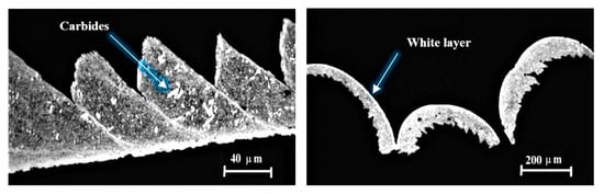
Figure 1.
An example of a “white layer” on the chip surface after processing improved steel [21].
The analysis of the obtained results proved that in the case of continuous and semi-interrupted processing, greater durability was recorded for the CBN-L tool. CBN-H tools showed better properties in the case of interrupted cuts, which is a direct result of much higher strength, heat resistance and higher ductility of these materials compared to CBN-L. The authors of the cited studies concluded that the microstructure of hardened steel had the main impact on the wear of the tested PCBN tools. These conclusions coincide with those of the current work [25,26,27].
The above research was continued in many studies [28,29,30], extending it with a Vc variable cutting speed. CBN 7015 with a TiN coating was used as cutting materials (tested Vc: 150, 250 m/min.) and uncoated CBN 7025 (tested Vc: 150, 195 m/min.). For continuous machining carried out with a lower Vc value, the main wear mechanism of both types of tools was abrasive wear, though was diffusion wear for higher Vc. For interrupted machining, in both cases intense abrasive and diffusion wear was noted, while the flank wear for the CBN 7015 tool was on average 3 times higher than for the 7025.
Another issue analyzed in the area of machining of hardened materials is the influence of protective coatings on the durability and wear of PCBN cutting tools.
Coelho et al. [18] analyzed the effect of anti-wear coatings on PCBN tool wear when machining AISI 4340 (EN40NiCrMo7) hardened steel. Three different TiN and TiC-based coatings were used for the tests. The analysis of the results showed that the tested coatings acted as a thermal barrier between the contact surface of the tool and the grains of the tool material.
The research results presented in the study [31] showed that the coatings on PCBN tools generally increase the chemical stability of the tool material, thus ensuring greater resistance to adhesive wear.
The authors of the work [32] stated, however, that at present the knowledge regarding the direct influence of protective coatings on the durability and wear of PCBN tools is insufficient to determine their usefulness in turning materials in an improved or hardened state.
The authors of the study [33] analyzed the condition of TiN and TiAlN coated cutting tools after finish turning of AISI D2 steel (EN X153CrMoV12). The lowest wear determined by the VB parameter was noted for TiN coated tools containing 50% of CBN in the tool material. On the other hand, the highest values of the tested parameter were obtained for TiAlN-coated tools with a CBN content of 65%.
The performed analysis showed that there is no clearly defined dependence of the influence of the type of tool material and protective coatings on the wear of PCBN cutting tools and the condition of the surface layer of the processed material.
When organizing cutting processes in a manufacturing system, the most complex problems arise when assessing the efficiency and reliability of machining with the use of specific cutting tools, including finish turning tools for improved AISI D2 tool steel (EN X153CrMoV12).
High quality requirements of the machined parts determine technological damage, which is the main object of research in the theory of technological system reliability [18,30,31]. During operation, the technological system is subject to thermal and mechanical effects, which cause damage and change the parameters of its initial state. During the operation of tools, along with the general principles of wear, special ones appear, often leading to their damage. Admittedly, the guides provide the permissible wear values at which the tool should be replaced, but they may differ significantly from those at which the cutting potential is fully used [25,26]. The dominant factor influencing the optimal conditions of tool operation is mainly damage caused by the wear of its cutting surfaces.
The aim of the study was to determine the technological feasibility of replacing the grinding operation of improved AISI D2 tool steel (EN X153CrMoV12) with turning machining using commercially available PCBN cutting blades. The article describes the effect of TiN and TiAlN coatings applied on PCBN-cutting tools on the condition of surface layer and the condition of cutting tools after hard turning. It shows a number of disadvantages of using uncoated tools for turning of a given material, e.g., related to shorter tool life or the occurrence of adverse phenomena on the machined surfaces (chip adhesion, the side flow phenomenon), which negatively affect the shape of the bearing area curves, and thus affected the operational properties of the machined surfaces.
2. Materials and Methods
The research included AISI D2 (EN X153CrMoV12) high-carbon high-chromium cold work tool steel, which is most often used as a material for dies, punches and forming rolls [26]. Its chemical composition is presented in Table 1. Samples in the form of rolls with a diameter of Ø = 50 mm, l = 20 mm were subjected to volume quenching in oil at a temperature of 1020 °C and tempering at a temperature of 150 °C to the assumed hardness of 63 ± 2 HRC. The obtained material structure is characterized by the presence of large primary (1) and secondary (2) carbides formed during tempering (Figure 2), the microhardness of which is even three times higher than the hardness of the obtained martensitic matrix of the strip-like material [34,35].

Table 1.
Chemical composition of AISI D2 steel (EN X153CrMoV12) [36].
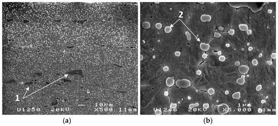
Figure 2.
The structure of the material used in research where: (a) magnification 500×, 1—primary carbides, (b) magnification 5000×, 2—secondary carbides.
The machining was performed using the CTX 510 machining centre (DMG Mori, Nagoya, Japan) with the following cutting parameters: Vc = 160 m/min, ap = 0.2 mm, f = 0.1; 0.2; 0.3 mm/rev. The PDJNR2020K11 holder knife was used in the research (κr = 93°, α = 6°, γ = −6°) with DNGA 110408 replaceable inserts (re = 0.8 mm). The material of the cutting tools is presented in Table 2.
Table 2.
Material of the cutting tools adopted for the test.
A JEOL JSM-6400 scanning microscope (Tokyo, Japan) was used for metallographic examinations. The condition of the surface layer of machined surfaces (Ra, Rz, RSm parameters, bearing area curves) and cutting tools was assessed on the three-axis optical measurement system Alicona Infinite SL coupled with the IF-Laboratory Measurement Module (Graz, Austria).
A ZWICK ZHV10 microhardness tester (Wroclaw, Poland) was used to test the depth and degree of material reinforcement. HV0.01 microhardness was measured by keeping the distance between the impressions in each direction of no less than 2.5 of impression diagonal.
Due to the requirements of the tool manufacturers, the machining of “hard” materials with PCBN tools is always performed “dry”.
A new cutting tool and a new sample was used for each operation. A lack of roughness measurement results for turning with a T5 blade with a feed f2 = 0.2 mm/rev. resulted from surface layer damage during turning.
3. Results and Discussion
The analysis of the geometric structure of the machined surfaces was carried out by comparing the values of the key roughness parameters: Ra—arithmetical mean height, Rz—maximum height of profile and RSm—mean width of the profile elements [36,37].
Figure 3 shows the obtained results of measurements of selected roughness parameters Ra, Rz and RSm depending on the f feed value and the type of tools.
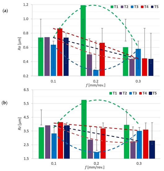
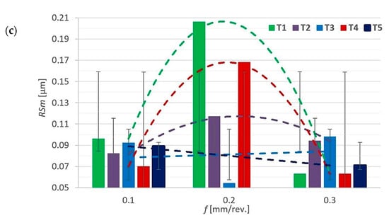
Figure 3.
Values of selected parameters of surface roughness depending on the value of f feed and the type of cutting edge where: T1–T5—tool number; (a)—Ra (µm); (b)—Rz (µm); (c)—RSm (µm).
For feeds f1 = 0.1 mm/rev. and f3 = 0.3 mm/rev. the roughness parameter Ra values for all tested cutting tools are similar and have a downward trend (Figure 3a). For the feed f2 = 0.2 mm/rev. for the only uncoated tool T1 among the tested, a sudden increase in the analyzed parameter was noted. The same dependence can be noticed for the results of the Rz parameter measurement (Figure 3b). The microscopic analysis of the tool T1 condition showed the most intense adhesive wear occurring on the flank surfaces after machining with feeds f2 = 0.2 mm/rev. and f3 = 0.3 mm/rev. (Figure 4a,b). For all coated tools, especially T2 and T3, these phenomena occurred with much less intensification (Figure 4c,d).
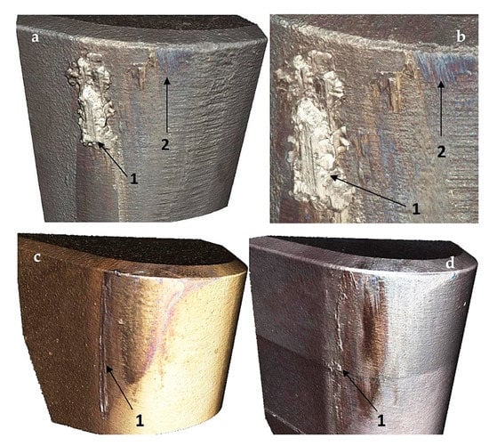
Figure 4.
(a,b): T1 tool after machining with the feed value f3 = 0.3 mm/rev., magnification 500×; 1—adhesive wear, 2—abrasive wear; T2 (c) and T3 (d) tool after machining with the feed value f3 = 0.3 mm/rev., magnification 200×; 1—adhesive wear.
For feed f2 = 0.2 mm/rev., the occurrence of numerous chip sticking and the phenomenon of material side flow occurring on the T1 tool-machined surfaces was also noted (Figure 5a,b). Both phenomena could be caused by different tribological properties of the tested tools and different heat distribution in the cutting zone. The uncoated T1 tools, characterized by a higher coefficient of friction than the coated ones, generate a higher temperature in the cutting zone [38]. This, in turn, might have resulted in the plastification of the processed material, leading to the phenomenon of material side flow as well as frequent chip sticking on the processed surface [5], which caused the abnormal increase of roughness parameters (Figure 3). These phenomena did not occur on surfaces machined with coated blades, an example of which is shown in Figure 5c,d.
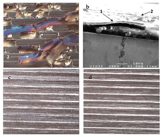
Figure 5.
(a,b): The surface treated with an uncoated T1 tool with the feed value f2 = 0.2 mm/rev.; 1—side flow of the material, 2—chip glued on the surface; (c,d): the surfaces treated with coated T2 (c) and T3 (d) tools with the feed value f2 = 0.2 mm/rev.; magnification 200×.
The largest decrease and, at the same time, the lowest value of all tested parameters of the roughness of the machined surfaces were recorded for the TiAlN coated tools T3 for the feed f2 = 0.2 mm/rev. These tools were the only ones that recorded a decrease in the value of the RSm parameter, including for the feed f2 = 0.2 mm/rev., while for all other tools, the value of this parameter increased. However, the T3 tools were the only ones to record an increase in all tested roughness parameters for the feed f3 = 0.3 mm/rev., which, according to the tool’s manufacturer, is the upper limit of the working range for this type of tool.
The smallest differences in the measurement results of the tested roughness parameters depending on the feed value characterize the T2 tools as the only ones with a TiN coating and show them to characterized by the highest shear angle among the tested tools, i.e., 30°.
In general, it should be assumed that the lowest values were recorded for the material treated with T3 tools, and for the material treated with T1 tools, the highest values of the tested roughness parameters were noted.
All the average measurement results of the roughness parameters Ra and Rz for the f1 feed significantly exceed the theoretical values given by the manufacturers of individual tools.
Figure 6, Figure 7 and Figure 8 show the bearing area curve for the surfaces processed with the tested tools and for the entire range of the tested feeds.
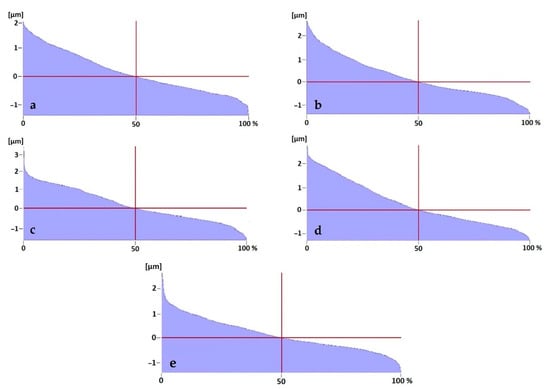
Figure 6.
Bearing area curves for the surfaces processed with the T1–T5 tools with feed f1 = 0.1 mm/rev.: (a): T1; (b): T2; (c): T3; (d): T4; (e): T5.
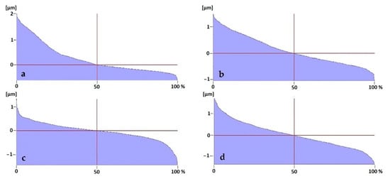
Figure 7.
Bearing area curves for the surfaces processed with the T1–T4 tools with feed f2 = 0.2 mm/rev.: (a): T1; (b): T2; (c): T3; (d): T4.
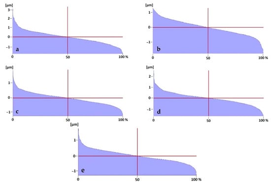
Figure 8.
Bearing area curves for the surfaces processed with the T1–T5 tools with feed f3 = 0.3 mm/rev.: (a): T1; (b): T2; (c): T3; (d): T4; (e): T5.
The analysis of the bearing area curves shows the advantage of increasing the feed value during the turning process of the tested material. The progressive nature of the curves, indicating good operational properties of the processed material—in particular its high abrasion resistance [39]—was observed for all surfaces processed with a feed of f3 = 0.3 mm/rev.
The desired shape of the bearing area curve, after turning with a feed of f2 = 0.2 mm/rev., was only observed for the surface processed with the T3 tool. The remaining curves, including all those obtained after turning with a feed of f1 = 0.1 mm/rev. have a digressive shape, which possibly indicates insufficient operational properties for these surfaces [40].
Figure 9 shows the results of research on the depth and degree of strengthening of the surface layer of the processed material with the feed value f3 = 0.3 mm/rev. Figure 10 presents the surface hardening rate of the surface layer after machining with the same feed value.
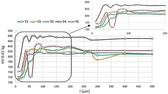
Figure 9.
Microhardness of the material processed with the feed f3 = 0.3 mm/rev. depending on the tested tool where: T1–T5—tool type.
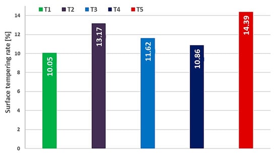
Figure 10.
Surface tempering rate of the material processed with the feed f3 = 0.3 mm/rev. depending on the tested tool where: T1–T5—tool type.
The greatest changes in the microhardness of the material occur for the surface layer depth of approximately 100 µm. For all tested surfaces, the hardness of the material core was achieved at a depth of 400–500 µm from the outer border of the processed material (Figure 9). The presented test results prove a very similar degree of material tempering for all tested cutting tools (defined as the percentage difference between the microhardness of the surface and the material core—as shown in Figure 9).
The lowest degree of tempering (10.05%) was obtained for the material treated with the T1 uncoated tool. The largest one (14.39%) was the material treated with the T5 TiAlN-coated tool. The reason for this could have been the largest (65%) share of CBN in the composition of the T5 tool material out of all the examined tools, resulting in less heat being transferred to the tool and more heat being passed on to the processed material. This can be confirmed by the sudden decrease of microhardness at the surface layer depth of about 50–60 µm, which may indicate the presence of high temperatures causing material tempering at this depth. However, it should be taken into account that the measurement value could have been influenced by the structure of the material obtained during thermal improvement, characterized by both an uneven primary and secondary distribution of carbides that was much harder than the matrix.
4. Conclusions
In the presented research, the influence of anti-wear coatings applied on PCBN cutting tools on selected parameters characterizing the condition of the surface layer after finish turning of AISI D2 tool steel (EN X153CrMoV12) was analyzed. The performed analysis allows drawing the following cognitive conclusions:
- a positive effect of the use of anti-wear coatings on PBCN tools has been shown to reduce the values of the roughness parameters tested compared to uncoated tools,
- the lowest influence of the feed on the values of all tested roughness parameters was noted for surfaces treated with TiN-coated T2 tools (50 vol.% of CBN) and TiAlN-coated T3 (50 vol.% of CBN) tools,
- the lack of protective coating contributed to the occurrence of intense adhesive wear on the flank surface on the uncoated T1 tools, in the range of the feed values f = 0.2 and 0.3 [mm/rev.],
- the analysis of material surface after treatment with the uncoated T1 tool with the feed f = 0.2 [mm/rev.] showed the occurrence of the phenomenon of lateral material flow and numerous chip deflections,
- for all tested tools, the greatest changes in the microhardness of the structure after the turning process with a feed f = 0.3 [mm/rev.] were obtained for a depth of up to 100 µm, and the hardness of the material core for all tested tools was achieved at a depth of 400–500 µm from the outside material boundary,
- the most optimal parameters of the surface layer, equivalent to parameters after the grinding process, for all analyzed materials were obtained after processing with a feed value of f = 0.3 mm/rev.
Author Contributions
Conceptualization, M.O. and M.J.; methodology, M.J.; software, M.O.; validation, P.K. and M.J.; formal analysis, M.J. and P.K.; investigation, M.O., M.J. and P.K.; resources, M.J. and P.K.; data curation, P.K.; writing—original draft preparation, M.O.; writing—review and editing, P.K.; visualization, M.O.; supervision, M.J.; All authors have read and agreed to the published version of the manuscript.
Funding
The authors gratefully acknowledge the financial support from the program of the Polish Ministry of Science and Higher Education under the name “Regional Initiative of Excellence” in 2019–2022, project No. 003/RID/2018/19, funding amount 11 936 596.10 PLN”.
Institutional Review Board Statement
Not applicable.
Informed Consent Statement
Not applicable.
Data Availability Statement
The data presented in this study are available in article.
Conflicts of Interest
The authors declare no conflict of interest.
References
- Rao, J.; Sharma, A.; Rose, T. Titanium aluminium nitride and titanium boride multilayer coatings designed to combat tool wear. Coatings 2017, 8, 12. [Google Scholar] [CrossRef]
- Boing, D.; Zilli, L.; Fries, C.E.; Schroeter, R.B. Tool wear rate of the PCBN, mixed ceramic, and coated cemented carbide in the hard turning of the AISI 52100 steel. Int. J. Adv. Manuf. Technol. 2019, 104, 4697–4704. [Google Scholar] [CrossRef]
- Radha Krishnan, B.; Aravindh, R.; Barathkumar, M.; Gowtham, K.; Hariharan, R. Prediction of surface roughness (AISI 4140 steel) in cylindrical grinding operation by RSM. Int. J. Res. Dev. Technol. 2018, 9, 702–704. [Google Scholar]
- Puerto, P.; Fernandez, R.; Madariaga, J.; Arana, J.; Gallego, I. Evolution of surface roughness in griding and its relationship with the dressing parameters and the radial wear. Procedia Eng. 2013, 63, 174–182. [Google Scholar] [CrossRef]
- Ociepa, M.; Jenek, M.; Feldshtein, E.; Leksycki, K. The phonomenon of material side flow during finish turning of EN X153CrMoV12 hardened steel with tools based on polycrystalline cubic boron nitride. J. Superhard Mater. 2019, 41, 265–271. [Google Scholar] [CrossRef]
- Tillmann, W.; Elrefaey, A.; Wojarski, L. Brazing of cutting tools. In Advances in Brazing—Science, Technology and Applications; Elsevier: Amsterdam, The Netherlands, 2013; pp. 423–471. [Google Scholar]
- Bushlya, V.M.; Gutnichenko, O.A.; Zhou, J.M.; Ståhl, J.-E.; Gunnarsson, S. Tool wear and tool life of PCBN, binderless cBN and wBN-cBN tools in continuous finish hard turning of cold work tool steel. J. Superhard Mater. 2014, 36, 49–60. [Google Scholar] [CrossRef]
- DIN ISO 513:2014–05. Classification and Application of Hard Cutting Materials for Metal Removal with Defined Cutting Edges—Designation of the Main Groups and Groups of Application (ISO 513:2012); Deutsches Institut für Normung: Berlin, Germany, 2014. [Google Scholar]
- Gsander, D. Chancen und Gränzen des high-performance cutting. Werkzeug Tech. 2002, 72, 35–37. [Google Scholar]
- Gordon, S.; Phelan, P.; Lahiff, C. The effect of high speed machining on the crater wear behaviour of PCBN tools in hard turning. Procedia Manuf. 2019, 38, 1833–1848. [Google Scholar] [CrossRef]
- Sveen, S.; Andersson, J.; M’Saoubi, R.; Olsson, M. Scratch adhesion characteristics of PVD TiAlN deposited on high speed steel, cemented carbide and PCBN substrates. Wear 2013, 308, 133–141. [Google Scholar] [CrossRef]
- Sousa, V.F.C.; Silva, F.J.G. Recent advances in turning processes using coated tools—A comprehensive review. Metals 2020, 10, 170. [Google Scholar] [CrossRef]
- Micallef, C.; Zhuk, Y.; Aria, A.I. Recent progress in precision machining and surface finishing of tungsten carbide hard composite coatings. Coatings 2020, 10, 731. [Google Scholar] [CrossRef]
- Caliskan, H.; Panjan, P.; Kurbanoglu, C. Hard Coatings on Cutting Tools and Surface Finish. In Comprehensive Materials Finishing; Elsevier: Amsterdam, The Netherlands, 2017; Chapter 3; pp. 230–242. [Google Scholar] [CrossRef]
- Taylan, F.; Colak, O.; Kayacan, M. Investigation of TiN coated CBN and CBN cutting tool performance in hard milling appli-cation, Strojniski vestnik. J. Mech. Eng. 2011, 57, 417–424. [Google Scholar]
- Galoppi, G.D.S.; Filho, M.S.; Batalha, G.F. Hard turning of tempered DIN 100Cr6 steel with coated and no coated CBN inserts. J. Mater. Process. Technol. 2006, 179, 146–153. [Google Scholar] [CrossRef]
- M’Saoubi, R.; Johansson, M.; Andersson, J. Wear mechanisms of PVD-coated PCBN cutting tools. Wear 2013, 302, 1219–1229. [Google Scholar] [CrossRef]
- Coelho, R.T.; Ng, E.-G.; Elbestawi, M. Tool wear when turning hardened AISI 4340 with coated PCBN tools using finishing cutting conditions. Int. J. Mach. Tools Manuf. 2007, 47, 263–272. [Google Scholar] [CrossRef]
- Sousa, V.; Da Silva, F.; Pinto, G.; Baptista, A.; Alexandre, R. Characteristics and wear mechanisms of TiAlN-based coatings for machining applications: A comprehensive review. Metals 2021, 11, 260. [Google Scholar] [CrossRef]
- Kuo, C.-C.; Lin, Y.-T.; Chan, A.; Chang, J.-T. High temperature wear behavior of titanium nitride coating deposited using high power impulse magnetron sputtering. Coatings 2019, 9, 555. [Google Scholar] [CrossRef]
- Badini, C.; Deambrosis, S.M.; Padovano, E.; Fabrizio, M.; Ostrovskaya, O.; Miorin, E.; D’Amico, G.C.; Montagner, F.; Biamino, S.; Zin, V. Thermal shock and oxidation behavior of HiPIMS TiAlN coatings grown on Ti–48Al–2Cr–2Nb intermetallic alloy. Materials 2016, 9, 961. [Google Scholar] [CrossRef] [PubMed]
- Manokhin, A.S.; Klimenko, S.A.; Klimenko, S.A.; Beresnev, V.M. Promising types of coatings for PCBN tools. J. Superhard Mater. 2018, 40, 424–431. [Google Scholar] [CrossRef]
- Poulachon, G.; Bandyopadhyay, B.; Jawahir, I.; Pheulpin, S.; Seguin, E. The influence of the microstructure of hardened tool steel workpiece on the wear of PCBN cutting tools. Int. J. Mach. Tools Manuf. 2003, 43, 139–144. [Google Scholar] [CrossRef]
- Yamamoto, K.; Inthidech, S.; Sasaguri, N.; Matsubara, Y. Influence of Mo and W on high temperature hardness of M7C3 carbide in high chromium white cast iron. Mater. Trans. 2014, 55, 684–689. [Google Scholar] [CrossRef]
- Dziedzic, K.; Józwik, J.; Barszcz, M.; Gauda, K. Wear characteristics of hard facing coatings obtained by tungsten inert gas method. Adv. Sci. Technol. Res. J. 2019, 13, 8–14. [Google Scholar] [CrossRef]
- Pytlak, B. Multicriteria optimization of hard turning operation of the hardened 18HGT steel. Int. J. Adv. Manuf. Technol. 2010, 49, 305–312. [Google Scholar] [CrossRef]
- Boing, D.; Schroeter, R.B.; De Oliveira, A.J. Three-dimensional wear parameters and wear mechanisms in turning hardened steels with PCBN tools. Wear 2018, 398–399, 69–78. [Google Scholar] [CrossRef]
- De Godoy, V.A.A.; Diniz, A.E. Turning of interrupted and continuous hardened steel surfaces using ceramic and CBN cutting tools. J. Mater. Process. Technol. 2011, 211, 1014–1025. [Google Scholar] [CrossRef][Green Version]
- Grzesik, W. Advanced Machining Processes of Metallic Materials—Theory, Modeling and Applications, 2nd ed.; Elsevier: Amsterdam, The Netherlands, 2017; p. 578. ISBN 978-0-444-63711-6. [Google Scholar]
- Wang, Y.; Cui, X.; Xu, H.; Jiang, K. Cutting force analysis in reaming of ZL102 aluminium cast alloys by PCD reamer. Int. J. Adv. Manuf. Technol. 2012, 67, 1509–1516. [Google Scholar] [CrossRef]
- Fuentes, J.A.O.; Keunecke, M. Analysis and application of CBN coated cutting tools. In Proceedings of the 7th International Conference “The Coatings in Manufacturing Engineering”, Chalkidiki, Greece, 1–3 October 1998. [Google Scholar]
- Uhlmann, E.; Braeuer, G.; Wiemann, E.; Keunecke, M. CBN coatings on cutting tools, production engineering. Res. Dev. Ger. Ann. Ger. Acad. Soc. Prod. Eng. 2004, 11, 45–48. [Google Scholar]
- Ociepa, M.; Jenek, M.; Feldshtein, E. On the wear comparative analysis of cutting tools made of composite materials based on polycrystalline cubic boron nitride when finish turning of AISI D2 (EN X153CrMoV12) steel. J. Superhard Mater. 2018, 40, 396–401. [Google Scholar] [CrossRef]
- Krbaťa, M.; Eckert, M.; Križan, D.; Barényi, I.; Mikušová, I. Hot deformation process analysis and modelling of X153CrMoV12 steel. Metals 2019, 9, 1125. [Google Scholar] [CrossRef]
- Panjan, P.; Drnovšek, A.; Gselman, P.; Čekada, M.; Bončina, T.; Merl, D.K. Influence of growth defects on the corrosion resistance of sputter-deposited TiAlN hard coatings. Coatings 2019, 9, 511. [Google Scholar] [CrossRef]
- EN ISO 4957:2018. Tool Steels; ISO: Geneva, Switzerland, 2018. [Google Scholar]
- EN ISO 4287:1997. Geometrical Product Specifications (GPS)—Surface Texture: Profile Method—Terms, Definitions and Surface Texture Parameters; ISO: Geneva, Switzerland, 1997. [Google Scholar]
- Kumar, C.; Patel, S.K.; Majumder, H.; Khan, A.; Naik, D.K. Numerical analysis of hard machining of AISI 52100 steel using uncoated and coated Al2O3-TiCN based mixed ceramic inserts. In Proceedings of the National Conference on Emerging Trends in Manufacturing & Automation Engineering, NCMAE, Gwalior, India, 6 October 2017. [Google Scholar]
- Urban, M.; Monkova, K. Research of tribological properties of 34CrNiMo6 steel in the production of a newly designed self-equalizing thrust bearing. Metals 2020, 10, 84. [Google Scholar] [CrossRef]
- Salcedo, M.C.; Coral, I.B.; Ochoa, G.V. Characterization of surface topography with Abbott Firestone curve. Contemp. Eng. Sci. 2018, 11, 3397–3407. [Google Scholar] [CrossRef]


Publisher’s Note: MDPI stays neutral with regard to jurisdictional claims in published maps and institutional affiliations. |
© 2021 by the authors. Licensee MDPI, Basel, Switzerland. This article is an open access article distributed under the terms and conditions of the Creative Commons Attribution (CC BY) license (https://creativecommons.org/licenses/by/4.0/).