
Simulation to Microtopography Formation of CBN Active Abrasives on a Honing Wheel Surface


Abstract
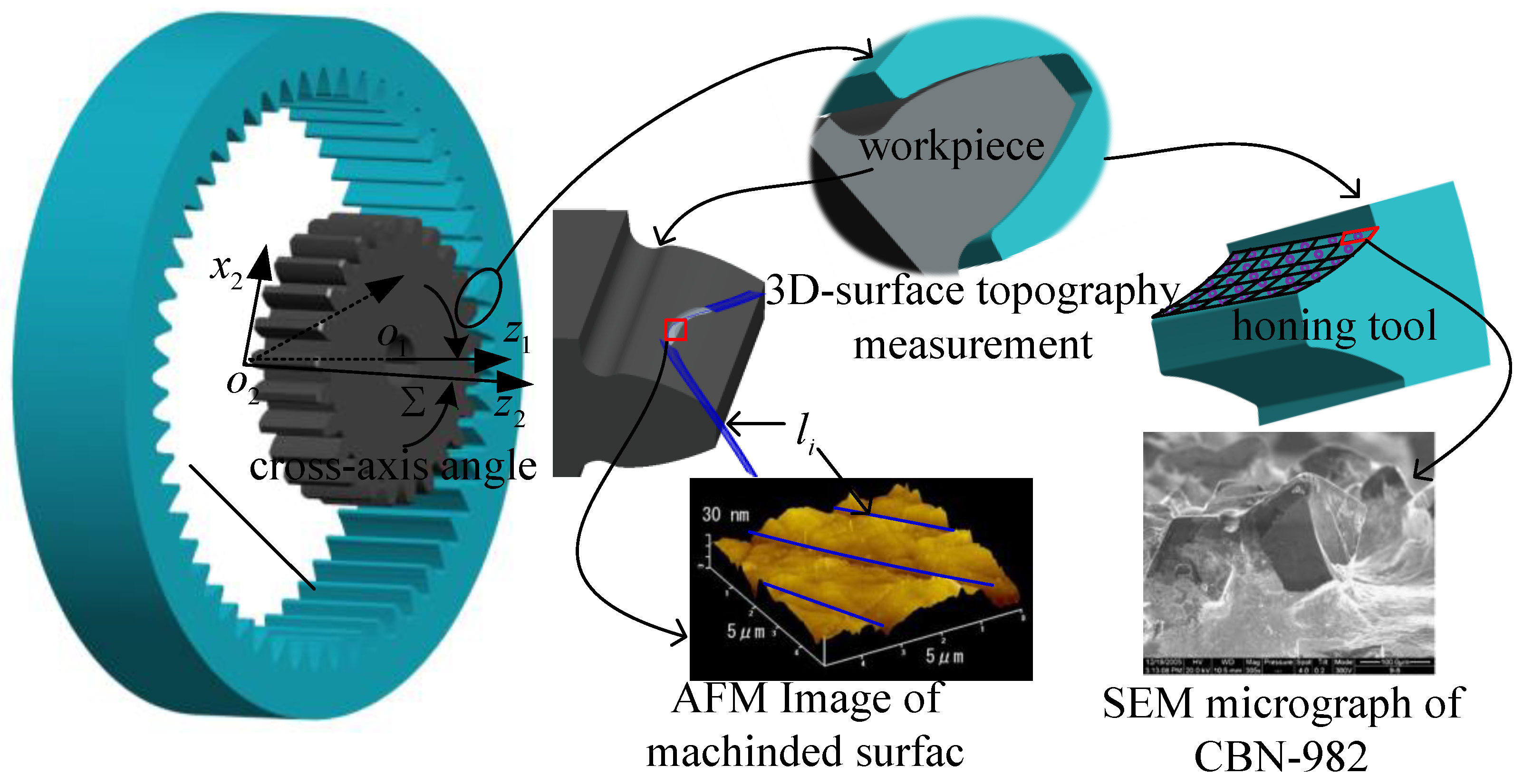
:1. Introduction
2. Simulation of the Micromorphology in the CBN Abrasive Growth Process
2.1. Phase Field Method
2.2. Equation Solution and Parameter Determination
2.3. Simulation Experiment
3. Discussion
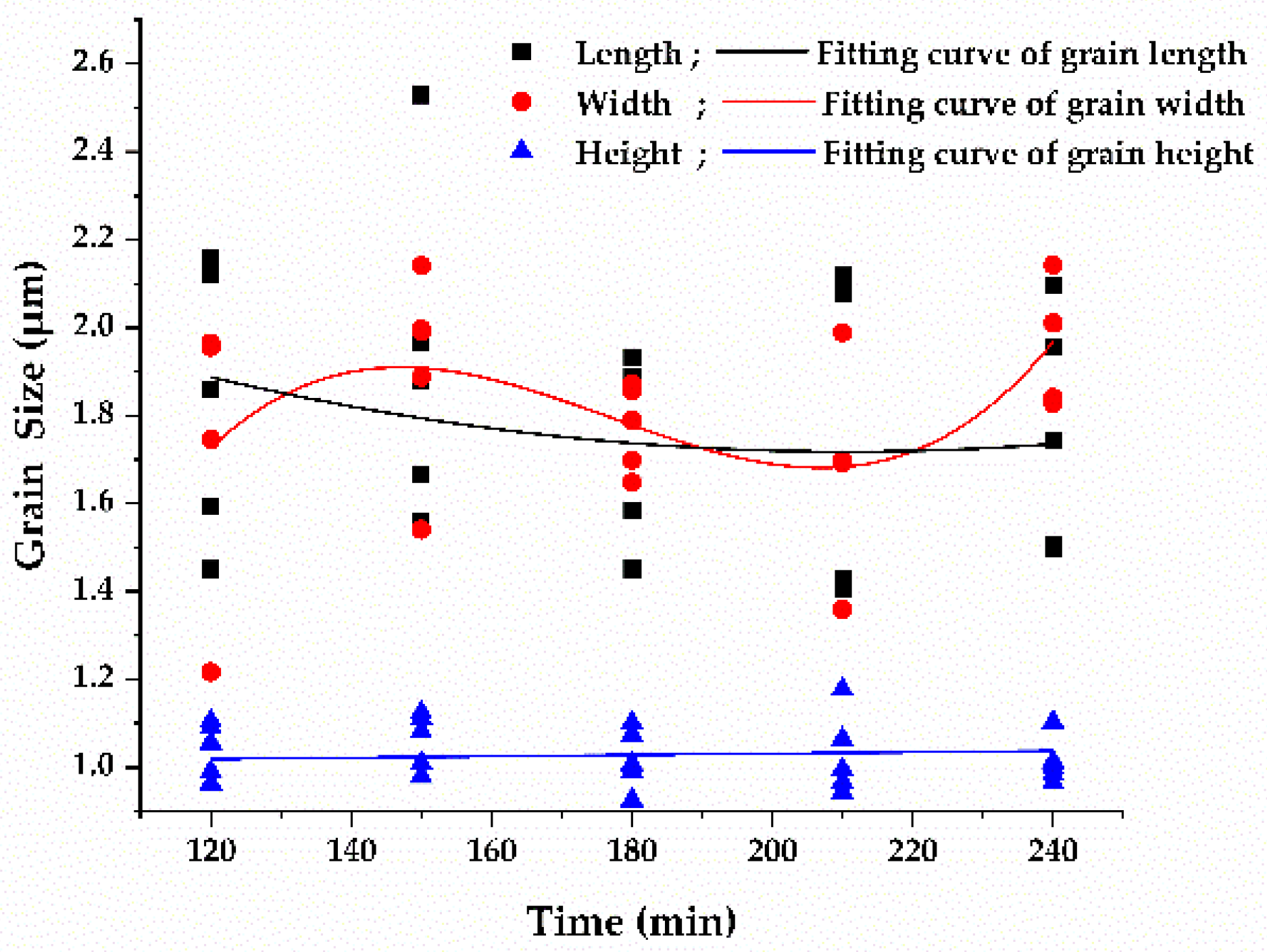
3.1. Effect of Sputtering Time on Abrasive Size
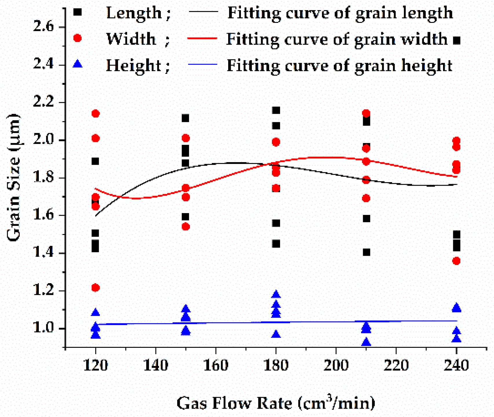
3.2. Effect of Substrate Temperature and Gas Flow Rate on Abrasive Size
3.3. Effect of Reaction Space on Abrasive Size and Active Abrasive Number
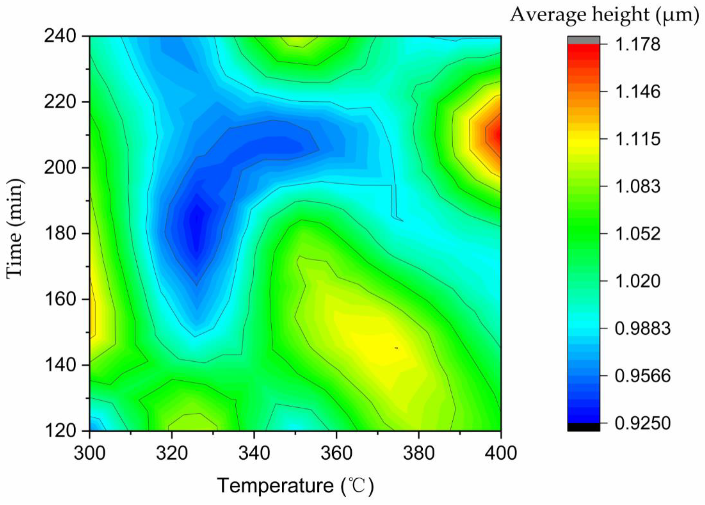
3.4. Effect of Substrate Temperature and Sputtering Time on the Grain Height
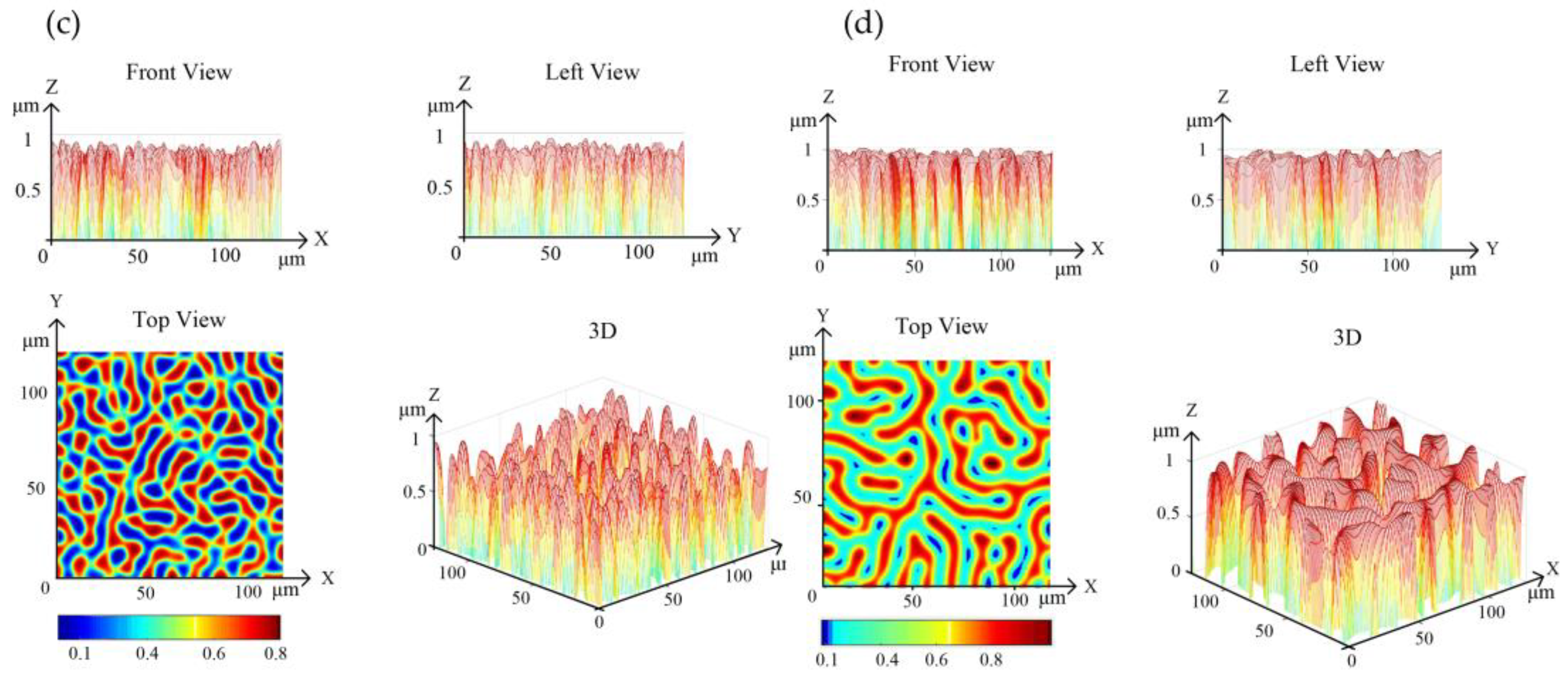
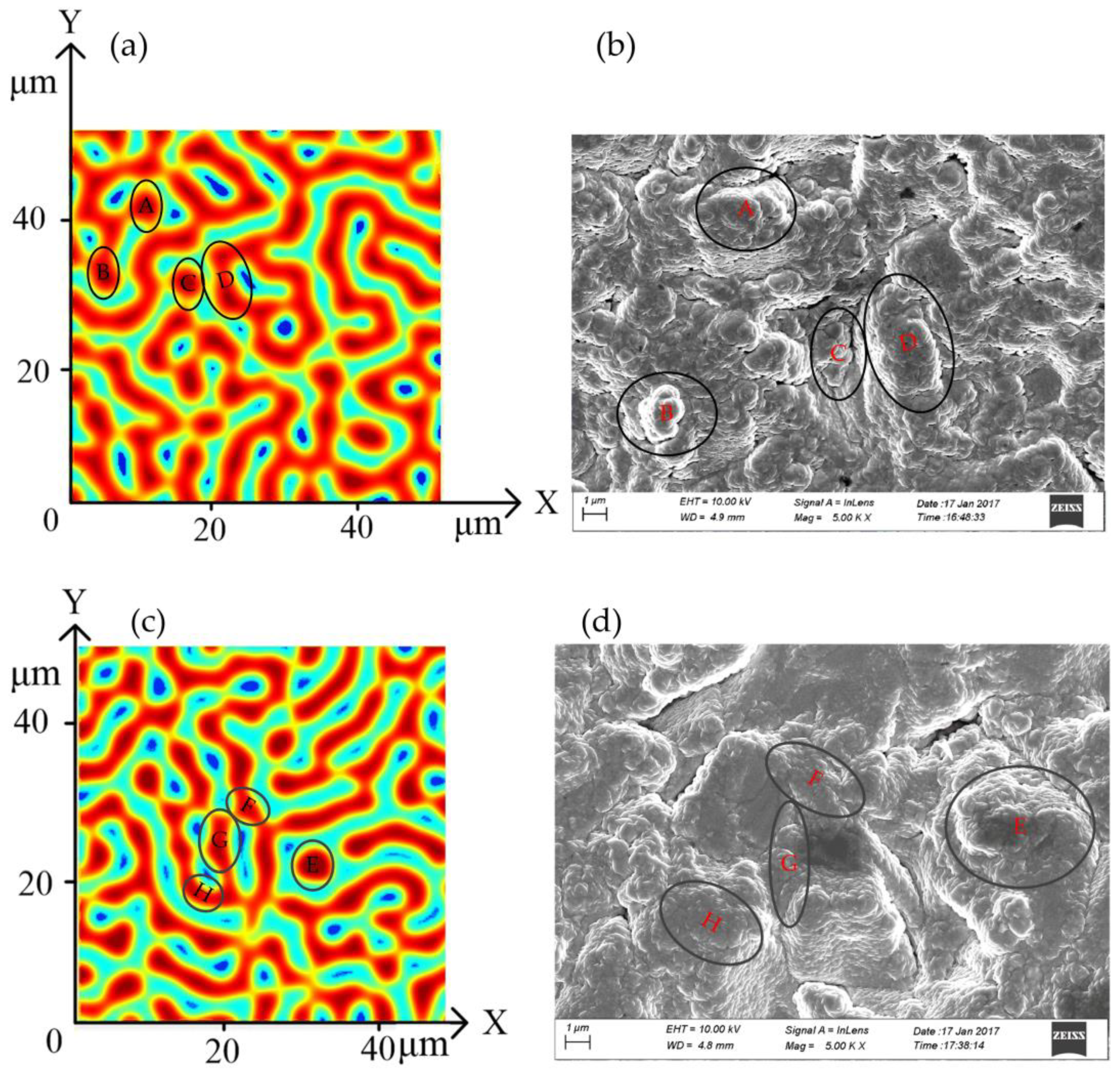
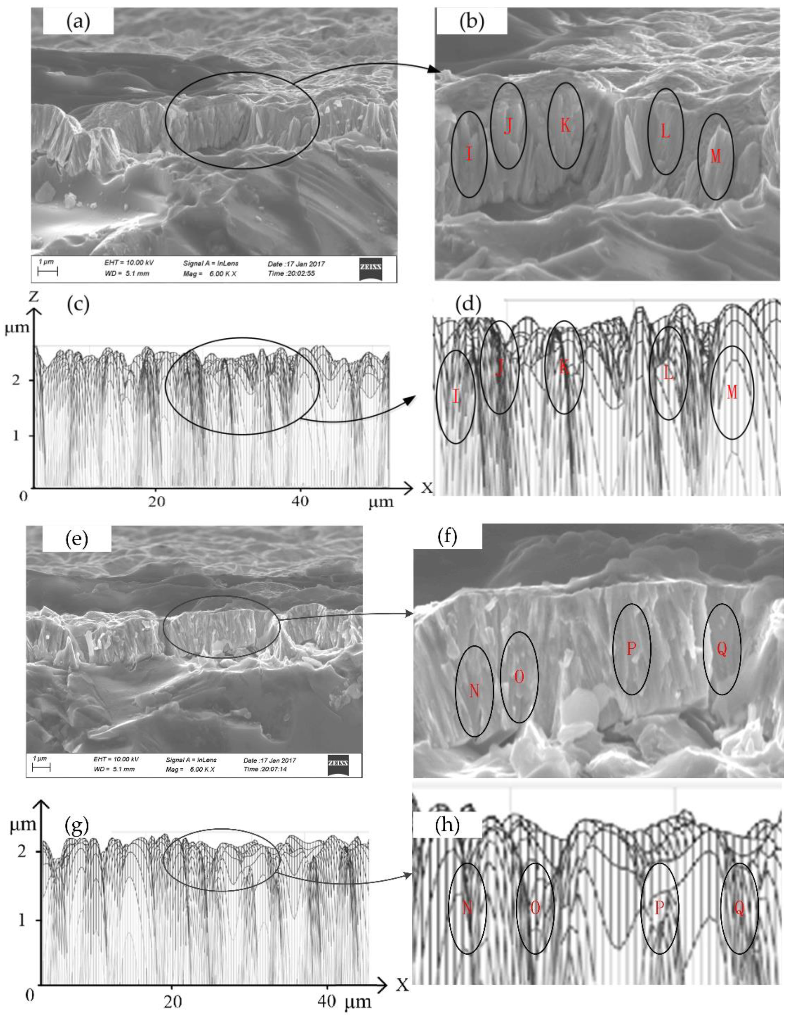
3.5. Comparison of Simulation and Experimental Results
4. Conclusions
- (1).
- By comparison of the simulation and experimental results, the method in this paper can effectively simulate the growth process of CBN abrasive grains, which grow from a single spherical shape to a long strip at the nucleation point, and the coating thickness grows from discontinuous and thin to a continuous and dense coating.
- (2).
- Plasma energy (energetic ions) drive the migration, rearrangement, coalescence, and nucleation of boron and nitrogen atoms in the matrix, providing the driving force for the growth, coarsening, and film formation of CBN grains. In addition, a higher plasma energy would increase the growth and coarsening rate of columnar grains and improve the film quality.
- (3).
- The effects of sputtering time, substrate temperature, gas flow rate, and reaction space on the number and size of CBN abrasive grains are of high significance, and should be mainly controlled. Process parameters have a low level of influence on the shape and spacing of active abrasive grains, and should be controlled as a secondary factor. Therefore, the reasonable selection or optimization of process parameters can quantitatively control the number, size, and distribution state of abrasive grains, optimize the micromorphology of CBN coating on the tooth surface of honing wheels, and promote the processing performance of honing wheels.
- (4).
- Despite the good agreement between the simulation and SEM experimental results, the model needs to be modified and improved in future studies due to the limitations of the selection of phase field parameters, solution accuracy, and computational volume of simulation. In future work, methods such as machine learning will be considered to optimize the parameters of the phase field model and improve the accuracy of the solution algorithm. In this way, it is possible to efficiently design the micromorphology of CBN grains on the tooth surface of honing wheels and produce high-performance honing wheels, thereby fundamentally improving the material removal rate, machining accuracy, and surface quality of hardened gears.
Author Contributions
Funding
Institutional Review Board Statement
Informed Consent Statement
Data Availability Statement
Conflicts of Interest
References
- Mallipeddi, D.; Norell, M.; Sosa, M.; Nyborg, L. Effect of Running-In (Load and Speed) on Surface Characteristics of Honed Gears. Tribol. Trans. 2019, 62, 412–418. [Google Scholar] [CrossRef]
- Pathak, S.; Jain, N.K. Critical review of electrochemical honing (ECH): Sustainable and alternative gear finishing process. Part 1: Conventional processes and introduction to ECH. Trans. IMF 2017, 95, 147–157. [Google Scholar] [CrossRef] [Green Version]
- He, Q.; Paiva, J.; Kohlscheen, J.; Beake, B.; Veldhuis, S. An integrative approach to coating/carbide substrate design of CVD and PVD coated cutting tools during the machining of austenitic stainless steel. Ceram. Int. 2020, 46, 5149–5158. [Google Scholar] [CrossRef]
- Layyous, A.A.; Yehezkeal, L.; Hristo, S.; Renato, B. Coated Cutting Tool. Patent, IHI BERNEX AG (4600 Olten, CH). 2020. Available online: https://www.freepatentsonline.com/EP2148940B1.html (accessed on 2 May 2021).
- Rodríguez-Barrero, S.; Fernández-Larrinoa, J.; Azkona, I.; De Lacalle, L.N.L.; Polvorosa, R. Enhanced Performance of Nanostructured Coatings for Drilling by Droplet Elimination. Mater. Manuf. Process. 2016, 31, 593–602. [Google Scholar] [CrossRef]
- Karpuschewski, B.; Knoche, H.-J.; Hipke, M. Gear finishing by abrasive processes. CIRP Ann. 2008, 57, 621–640. [Google Scholar] [CrossRef]
- Han, J.; Zhu, Y.; Xia, L.; Tian, X. A novel gear flank modification methodology on internal gearing power honing gear machine. Mech. Mach. Theory 2018, 121, 669–682. [Google Scholar] [CrossRef]
- Wegener, K.; Bleicher, F.; Krajnik, P.; Hoffmeister, H.-W.; Brecher, C. Recent developments in grinding machines. CIRP Ann. 2017, 66, 779–802. [Google Scholar] [CrossRef]
- Liu, J.-H.; Hung, C.-H.; Chang, S.-L. Design and manufacture of plunge shaving cutter for shaving gears with tooth modifications. Int. J. Adv. Manuf. Technol. 2009, 43, 1024–1034. [Google Scholar] [CrossRef]
- Inui, M.; Huang, Y.; Onozuka, H.; Umezu, N. Geometric simulation of power skiving of internal gear using solid model with triple-dexel representation. Procedia Manuf. 2020, 48, 520–527. [Google Scholar] [CrossRef]
- Deng, X.-Z.; Li, G.-G.; Wei, B.-Y.; Deng, J. Face-milling spiral bevel gear tooth surfaces by application of 5-axis CNC machine tool. Int. J. Adv. Manuf. Technol. 2013, 71, 1049–1057. [Google Scholar] [CrossRef]
- Alvarez, A.; Calleja, A.; Ortega, N.; De Lacalle, L.N.L. Five-Axis Milling of Large Spiral Bevel Gears: Toolpath Definition, Finishing, and Shape Errors. Metals 2018, 8, 353. [Google Scholar] [CrossRef] [Green Version]
- Klocke, F.; Brumm, M.; Kampka, M. Process model for honing larger gears. In Proceedings of the International Gear Conference 2014, Lyon, France, 26–28 August 2014; pp. 118–128. [Google Scholar]
- Zhang, S.; Zhang, G.; Ran, Y.; Wang, Z.; Wang, W. Multi-Objective Optimization for Grinding Parameters of 20CrMnTiH Gear with Ceramic Microcrystalline Corundum. Materials 2019, 12, 1352. [Google Scholar] [CrossRef] [Green Version]
- Brinksmeier, E.; Schneider, C. Grinding at very Low Speeds. CIRP Ann. 1997, 46, 223–226. [Google Scholar] [CrossRef]
- Bergs, T. Cutting force model for gear honing. CIRP Ann. 2018, 67, 53–56. [Google Scholar] [CrossRef]
- Brinksmeier, E.; Giwerzew, A. Hard gear finishing viewed as a process of abrasive wear. Wear 2005, 258, 62–69. [Google Scholar] [CrossRef]
- Gao, Y.; Han, J.; Li, L.H.; Liu, L.; Lv, F.G. Research on the internal power gear honing processing technology for hard tooth surface. J. Mech. Eng. Res. Dev. 2016, 39, 500–512. [Google Scholar]
- Amini, N.; Westberg, H.; Klocke, F.; Kollner, T. An experimental study on the effect of power honing on gear surface topography. Gear Technol. 1999, 16, 11–18. [Google Scholar]
- Klocke, F.; Kuchle, A. Manufacturing Processes 2: Grinding, Honing, Lapping; Springer: Berlin/Heidelberg, Germany, 2009; pp. 19–36. [Google Scholar]
- Lundin, D.; Minea, T.; Gudmundsson, J.T. High Power Impulse Magnetron Sputtering. Fundamentals, Technologies, Challenges and Applications; Elsevier: Amsterdam, The Netherlands, 2020. [Google Scholar]
- Sarakinos, K.; Alami, J.; Konstantinidis, S. High power pulsed magnetron sputtering: A review on scientific and engineering state of the art. Surf. Coat. Technol. 2010, 204, 1661–1684. [Google Scholar] [CrossRef]
- Wang, X.; Mi, W.; Chen, G.; Chen, X.; Yang, B. Surface morphology, structure, magnetic and electrical transport properties of reactive sputtered polycrystalline Ti1−xFexN films. Appl. Surf. Sci. 2012, 258, 4764–4769. [Google Scholar] [CrossRef]
- Lattemann, M.; Ulrich, S.; Ye, J. New approach in depositing thick, layered cubic boron nitride coatings by oxygen addition—structural and compositional analysis. Thin Solid Films 2006, 515, 1058–1062. [Google Scholar] [CrossRef]
- Kay, E. Microstructure of sputtered metal films grown in high- and low-pressure discharges. J. Vac. Sci. Technol. A 1988, 6, 3074–3081. [Google Scholar] [CrossRef]
- Sarakinos, K. A review on morphological evolution of thin metal films on weakly-interacting substrates. Thin Solid Films 2019, 688, 137312. [Google Scholar] [CrossRef]
- Harper, J.M.; Cuomo, J.J.; Gambino, R.J.; Kaufman, H.R. Modification of thin film properties by ion bombardment during deposition. Nucl. Instrum. Methods Phys. Res. Sect. B Beam Interact. Mater. Atoms 1985, 7–8, 886–892. [Google Scholar] [CrossRef]
- Zhang, X.W.; You, J.B.; Chen, N.F. Recent advances in synthesis and properties of cubic boron nitride films. J. Inorg. Mater. 2007, 22, 385–390. [Google Scholar]
- Banko, L.; Lysogorskiy, Y.; Grochla, D.; Naujoks, D.; Drautz, R.; Ludwig, A. Predicting structure zone diagrams for thin film synthesis by generative machine learning. Commun. Mater. 2020, 1, 1–10. [Google Scholar] [CrossRef] [Green Version]
- Noraas, R.; Somanath, N.; Giering, M.; Olusegun, O.O. Structural Material Property Tailoring Using Deep Neural Networks. In Proceedings of the 2019 AIAA Science and Technology Forum and Exposition (SciTech), San Diego, CA, USA, 7–11 January 2019. [Google Scholar]
- Srolovitz, D.; Anderson, M.; Grest, G.; Sahni, P. Grain growth in two dimensions. Scr. Met. 1983, 17, 241–246. [Google Scholar] [CrossRef]
- Wang, P.; He, W.; Mauer, G.; Mücke, R.; Vaßen, R. Monte Carlo simulation of column growth in plasma spray physical vapor deposition process. Surf. Coat. Technol. 2018, 335, 188–197. [Google Scholar] [CrossRef]
- Nita, F.; Mastail, C.; Abadias, G. Three-dimensional kinetic Monte Carlo simulations of cubic transition metal nitride thin film growth. Phys. Rev. B 2016, 93, 064107. [Google Scholar] [CrossRef]
- Müller, K. Stress and microstructure of sputter-deposited thin films: Molecular dynamics investigations. J. Appl. Phys. 1987, 62, 1796–1799. [Google Scholar] [CrossRef]
- Wendler, F.; Mennerich, C.; Nestler, B. A phase-field model for polycrystalline thin film growth. J. Cryst. Growth 2011, 327, 189–201. [Google Scholar] [CrossRef]
- Yang, S.; Zhong, J.; Chen, M.; Zhang, L. A Parametric Three-Dimensional Phase-Field Study of the Physical Vapor Deposition Process of Metal Thin Films Aiming at Quantitative Simulations. Coatings 2019, 9, 607. [Google Scholar] [CrossRef] [Green Version]
- Chen, L.Q.; Yang, W. Computer simulation of the domain dynamics of a quenched system with large number of non-conserved order parameters: The grain-growth kinetics. Phys. Rev. 1994, 50, 52–57. [Google Scholar] [CrossRef] [PubMed]
- Suwa, Y.; Saito, Y.; Onodera, H. Three-dimensional phase field simulation of the effect of anisotropy in grain-boundary mobility on growth kinetics and morphology of grain structure. Comput. Mater. Sci. 2007, 40, 40–50. [Google Scholar] [CrossRef]
- Elliott, C.M.; Zheng, S. On the cahn-hilliard equation. Arch. Ration. Mech. Anal. 1986, 96, 339–357. [Google Scholar] [CrossRef]
- Allen, S.M.; Cahn, J.W. A microscopic theory for antiphase boundary motion and its application to antiphase domain coarsening. Acta Met. 1979, 27, 1085–1095. [Google Scholar] [CrossRef]
- Warren, J.A.; Kobayashi, R.; Lobkovsky, A.E.; Carter, W.C. Extending phase field models of solidification to polycrystalline materials. Acta Mater. 2003, 51, 6035–6058. [Google Scholar] [CrossRef]
- Qiang, F.; Wang, Q.; Cheng, Z.R. Three-dimensional simulation of wheel topography. Key Eng. Mater. 2011, 487, 149–154. [Google Scholar]
- Ren, X.Q. Research on Coating Preparation and Processing Characteristics of CBN Honing Gear. Ph.D. Thesis, Ningxia University, Yinchuan, China, 2018. [Google Scholar]
- Ding, W.-F.; Xu, J.-H.; Chen, Z.-Z.; Su, H.-H.; Fu, Y.-C. Wear behavior and mechanism of single-layer brazed CBN abrasive wheels during creep-feed grinding cast nickel-based superalloy. Int. J. Adv. Manuf. Technol. 2010, 51, 541–550. [Google Scholar] [CrossRef]
- Kuriyagawa, T.; Nishihara, K.; Guo, Y.B.; Syoji, K.; Suzuki, S. Improvement of Machined Surface Quality in Ultra-Precision Plane Honing. Key Eng. Mater. 2003, 238-239, 137–142. [Google Scholar]
- Xu, F.; Zuo, D.W.; Zhang, X.H.; Hu, H.F.; Zhang, C.; Wang, M. Research Progress on Cubic Boron Nitride Film for Tool Coating. Bull. Chin. Ceram. Soc. 2012, 31, 295–300. [Google Scholar]
- Yoshida, T. Vapour phase deposition of cubic boron nitride. Diam. Relat. Mater. 1996, 5, 501–507. [Google Scholar] [CrossRef]
- Guillén-González, F.; Tierra, G. Second order schemes and time-step adaptivity for Allen–Cahn and Cahn–Hilliard models. Comput. Math. Appl. 2014, 68, 821–846. [Google Scholar] [CrossRef]
- Wang, S.-L.; Sekerka, R.F.; Wheeler, A.A.; Murray, B.T.; Coriell, S.R.; Braun, R.J.; McFadden, G.B. Thermodynamically-consistent phase-field models for solidification. Phys. D Nonlinear Phenom. 1993, 69, 189–200. [Google Scholar] [CrossRef]
- Keblinski, P.; Maritan, A.; Toigo, F.; Messier, R.; Banavar, J.R. Continuum model for the growth of interfaces. Phys. Rev. E 1996, 53, 759–778. [Google Scholar] [CrossRef] [PubMed]
- Lobkovsky, E.; Warren, J.A. Phase-field model of crystal grains. J. Cryst. Growth 2001, 225, 282–288. [Google Scholar] [CrossRef]


| Parameter | A | B | C | D | g0 |
|---|---|---|---|---|---|
| Value | 0.5 | 10 | 2.5 | 0.01 | 1 |
| Exp. No. | Process Parameters | Abrasive Morphology Parameters | ||||||||
|---|---|---|---|---|---|---|---|---|---|---|
| P1 | P2 | P3 | P4 | Q1 | Q2 | Q3 | ||||
| (μm) | (°C) | (min) | (cm3/min) | (n) | (μm) | Q31(μm) | Q32(μm) | Q33(μm) | Q34 | |
| 1 | 32 | 300 | 120 | 120 | 19 | 14.19 | 0.9636 | 1.217 | 1.4515 | 0.8384 |
| 2 | 32 | 325 | 150 | 150 | 16 | 15.23 | 0.979 | 1.541 | 1.8805 | 0.8195 |
| 3 | 32 | 350 | 180 | 180 | 20 | 15.44 | 1.0731 | 1.857 | 1.4515 | 1.2794 |
| 4 | 32 | 375 | 210 | 210 | 18 | 13.97 | 0.9955 | 1.691 | 1.4075 | 1.2014 |
| 5 | 32 | 400 | 240 | 240 | 19 | 15.03 | 0.9848 | 1.841 | 1.4995 | 1.2277 |
| 6 | 64 | 300 | 150 | 180 | 39 | 16.23 | 1.124 | 1.992 | 1.558 | 1.2786 |
| 7 | 64 | 325 | 180 | 210 | 63 | 13.46 | 0.9254 | 1.789 | 1.5845 | 1.1291 |
| 8 | 64 | 350 | 210 | 240 | 57 | 13.22 | 0.944 | 1.359 | 1.4295 | 0.9507 |
| 9 | 64 | 375 | 240 | 120 | 66 | 13.97 | 0.9984 | 2.01 | 1.508 | 1.3329 |
| 10 | 64 | 400 | 120 | 150 | 55 | 14.67 | 1.056 | 1.746 | 1.5925 | 1.0964 |
| 11 | 128 | 300 | 180 | 240 | 212 | 16.24 | 1.1009 | 1.873 | 1.4525 | 1.2895 |
| 12 | 128 | 325 | 210 | 120 | 197 | 17.07 | 0.9664 | 1.698 | 1.424 | 1.1924 |
| 13 | 128 | 350 | 240 | 150 | 204 | 15.91 | 1.1021 | 2.011 | 1.9575 | 1.0273 |
| 14 | 128 | 375 | 120 | 180 | 207 | 13.99 | 1.0912 | 1.745 | 2.159 | 0.8082 |
| 15 | 128 | 400 | 150 | 210 | 221 | 14.78 | 1.0093 | 1.888 | 1.968 | 0.9593 |
| 16 | 256 | 300 | 210 | 150 | 815 | 14.73 | 1.0643 | 1.697 | 2.118 | 0.8012 |
| 17 | 256 | 325 | 240 | 180 | 834 | 16.48 | 0.9652 | 1.828 | 1.7435 | 1.0485 |
| 18 | 256 | 350 | 120 | 210 | 858 | 15.98 | 0.9901 | 1.956 | 2.121 | 0.9222 |
| 19 | 256 | 375 | 150 | 240 | 847 | 14.57 | 1.1108 | 1.997 | 2.5295 | 0.7895 |
| 20 | 256 | 400 | 180 | 120 | 858 | 15.01 | 1.0076 | 1.648 | 1.8905 | 0.8717 |
| 21 | 512 | 300 | 240 | 210 | 3541 | 13.92 | 1.0126 | 2.143 | 2.098 | 1.0214 |
| 22 | 512 | 325 | 120 | 240 | 3505 | 14.76 | 1.1049 | 1.965 | 1.861 | 1.0559 |
| 23 | 512 | 350 | 150 | 120 | 3493 | 15.23 | 1.0808 | 2.141 | 1.6655 | 1.2855 |
| 24 | 512 | 375 | 180 | 150 | 3521 | 15.92 | 0.9908 | 1.699 | 1.9335 | 0.8787 |
| 25 | 512 | 400 | 210 | 180 | 3498 | 16.03 | 1.1772 | 1.989 | 2.0785 | 0.9569 |
| Reaction Space | Substrate Temperature | Sputtering Time | Ar Flow Rate | N2 Flow Fate | Sputtering Power |
|---|---|---|---|---|---|
| 48 μm × 48 μm | 350 °C | 120 min | 150 cm3/min | 30 cm3/min | 350 W/300 W |
Publisher’s Note: MDPI stays neutral with regard to jurisdictional claims in published maps and institutional affiliations. |
© 2021 by the authors. Licensee MDPI, Basel, Switzerland. This article is an open access article distributed under the terms and conditions of the Creative Commons Attribution (CC BY) license (https://creativecommons.org/licenses/by/4.0/).
Share and Cite
Gao, Y.; Ren, X.; Han, J.; Wang, F.; Liang, Y.; Liu, L. Simulation to Microtopography Formation of CBN Active Abrasives on a Honing Wheel Surface. Coatings 2021, 11, 540. https://doi.org/10.3390/coatings11050540
Gao Y, Ren X, Han J, Wang F, Liang Y, Liu L. Simulation to Microtopography Formation of CBN Active Abrasives on a Honing Wheel Surface. Coatings. 2021; 11(5):540. https://doi.org/10.3390/coatings11050540
Chicago/Turabian StyleGao, Yang, Xiaoqiang Ren, Jiang Han, Fuwei Wang, Yuan Liang, and Lin Liu. 2021. "Simulation to Microtopography Formation of CBN Active Abrasives on a Honing Wheel Surface" Coatings 11, no. 5: 540. https://doi.org/10.3390/coatings11050540