Abstract
The paper presents study results focused on the microstructural, mechanical, and physicochemical properties of B-Cr coatings obtained by means of modification of diffusion borochromized layers by diode laser beam. The studies were conducted on 145Cr6 tool steel. Diffusion borochromized layers were produced at 950 °C in powder mixture containing boron carbides as a source of boron and ferrochrome as a source of chromium. In the next step these layers were remelted using laser beam. Powers: 600, 900, and 1200 W were used during these processes. The microstructure, microhardness, chemical composition, as well as wear and corrosion resistance of newly-formed B-Cr coatings were determined. As a result of laser beam interaction, the diffusion borochromized layer was mixed with the steel substrate. The study showed that too low laser beam power causes cracks in the newly formed B-Cr coating, and on the other hand, too higher laser beam power causes deep remelting resulting in the loss of microhardness. The reduced corrosion resistance in comparison with diffusion borochromized layers was caused by occurrence cracks or deep remelting. For B-Cr coatings produced using laser beam power 600 W, a small decrease in wear resistance was observed, but note that this coating was much thicker than diffusion borochromized layers. On the other hand, laser beam power of 1200 W caused a significant decrease in wear resistance. Newly formed B-Cr coatings had an advantageous microhardness gradient between the layer and the substrate.
1. Introduction
In recent times, material science has been developing very strongly. Researchers very often take up problems related to the analysis of new materials produced by powder metallurgy [1], additive manufacturing [2], or foundry technologies [3]. Often this is not enough, because the surface of these materials has the same properties as their core, and the operating conditions require different properties for different zones on the cross section of the finished product. Materials with very good strength properties have a number of advantages, e.g., greater durability or greater resistance to mechanical stress, but there are problems with their machining. These are often associated with significant wear of the cutting tools. Thus, hybrid methods are used [4]. However, their application is quite complicated. Therefore, other technologies which lead to the improvement of surface properties are needed in those instances. One of major technologies of material processing is heat treatment. It enables improvement of properties by changing the microstructure both within the core of the material and in the subsurface zone [5]. Heat treatment is a rather universal method, because it can be used not only to improve the surface properties of ferrous materials, but also for other alloys such as copper or aluminium alloys [6]. Very often, instead of traditional heat treatment, thermo-chemical treatment is used to refine the top layer of the material [7]. Carburizing and nitriding are widely used in the industry. Diffusion boronizing process is less widespread, but gives very similar results, and in some respects even better results [8]. The layer produced during this process is characterized by high hardness, reaching the value of up to about 2000 HV when produced by iron alloys. The boron layers are also characterized by good wear resistance caused by friction and corrosion [5]. When assessing diffusion-boronized layers and assigning them to a specific application, particular attention should be paid to their brittleness at the subsurface zone. This is undoubtedly a disadvantage of boronized layers, which largely limits their use. Therefore, research is carried out on manufacturing methods that will reduce brittleness, but which will not deteriorate those properties which are the advantages of boronized layers. Information can be found in the literature on the use of processes involving simultaneous introduction of boron and additional chemical elements. These can be, for example, carbon [9], copper [10], aluminium [11], or chromium [10,12,13,14,15,16]. The application of the process consisting of diffusive saturation with boron and chromium contributes to reduction of brittleness; the produced layer thus has a hardness similar to the boronized layer.
In ref. [10], the results of diffusion boronizing and borochromizing processes of die steels in a fluidized bed were described. The specimens were saturated at a temperature of 850–1000 °C for 30–120 min. The sources of boron included B4C (in the boronizing process), while the source of chromium was CrCl2 (in the borochromizing process). The author stated that after borochromizing, the microbrittleness in the layers decreased in comparison to the boronized layers. It was found that the layers were characterized by slightly decreased microhardness as well as increased wear resistance. In ref. [12], the 45 steel was borochromized in medium consisting of 4B + 7Cr2O3 + 89Li at 950 °C for 8 h. The obtained surface layers had a maximum microhardness of 22 GPa. The maximum contents of boron and chromium on the formed surface were, respectively, 13.8 wt.%–16.6 wt.% and 10.4 wt.%–16.6 wt.%. The authors analyzed deformation processes that arise between contacting surfaces with different physico-mechanical characteristics in static loading and stated that the strength properties of surface layers determined influence on the resistance to contact loading. The borochromized layer deforms substantially and fractures only upon attaining stresses close to those that cause fracture of micro-asperities and are larger by an order of magnitude than those in the uncoated steel. The presented data can be useful for the analysis of wear mechanisms and choice of tribomaterials. In refs. [15,16], the authors produced a B-Cr duplex-alloyed coating on the steel using a two-step pack cementation process (preboronizing and chromizing). Ferroboron, as a source of boron, was used for preboronizing, while chromium was used for the diffusion chromizing process. The boronized process was carried out at 950 °C for 3 h, whereas the chromized process at 1000 °C for 1 h. Both box-type furnace heating and induction heating were employed for chromizing to investigate the effect of heating and cooling rates on the microstructure and properties of the B-Cr coating. The authors stated that the heating mode of the second step of process (chromizing) has a significant effect on the phase composition and microstructure of the B-Cr coating. As a result of the conducted research, it was found that the efficiency of induction heating is higher than that of the box furnace heating, resulting in a thicker, denser, flatter surface, and B-Cr coating with fully reacted B and Cr elements. It was found that wear and corrosion resistance of the steel was significantly improved by the formation of such coating.
Despite the fact that there are relatively few publications on diffusion layers containing boron and chromium, undoubtedly these chemical elements are worth paying attention in the context of introducing them to steel surface. The boronizing process may have a positive effect on durability improvement of tools for mining as well as for dies or rolls using in metal forming processes (rolling, punching, stamping, or forging) [17,18,19,20,21,22,23,24,25,26,27,28,29,30,31,32,33,34]. Diffusion chrome plating has a number of useful applications, such as increasing durability of tool surfaces in foundry processes and also in plastic forming processes [22,23,24,25].
Recently, methods using high-energy sources, such as lasers, have played an important role among surface modification methods [26,27,28,29,30,31,32,33,34,35,36,37,38,39]. The use of a laser beam allows the microstructure of the previously produced surface layer to be shaped, giving it new properties. In this context, it is very important to the improvement in wear resistance by friction and to create a favorable hardness gradient between the layer and the treated substrate. The main goal of laser treatment is to ensure a longer life span of the manufactured product [28,30,38]. As a result of laser beam surface modification, it is possible to obtain such a microstructure of the material that will have unique properties previously unobtainable by traditional diffusion methods. There are publications available in worldwide scientific databases describing the production of modern layers by laser modification of diffusion layers. This applies mainly to studies related to boronizing process [25,30,31,32], but also to boroncarburizing [26] and chromizing [39]. However, there is no information in the literature on research on production of borochromized layers and their modification with a laser beam.
Therefore, it seems important to undertake research on laser modification of borochromized layers. This paper presents the results of tests of microstructure, phase and chemical composition, microhardness, corrosion resistance, and wear resistance of borochromized layers modified with a diode laser beam.
2. Materials and Methods
Borochromized layers and B-Cr laser-modified coatings were produced on 145Cr6 tool steel. Chemical composition of substrate material is given in Table 1.

Table 1.
Chemical composition of steel used [wt.%].
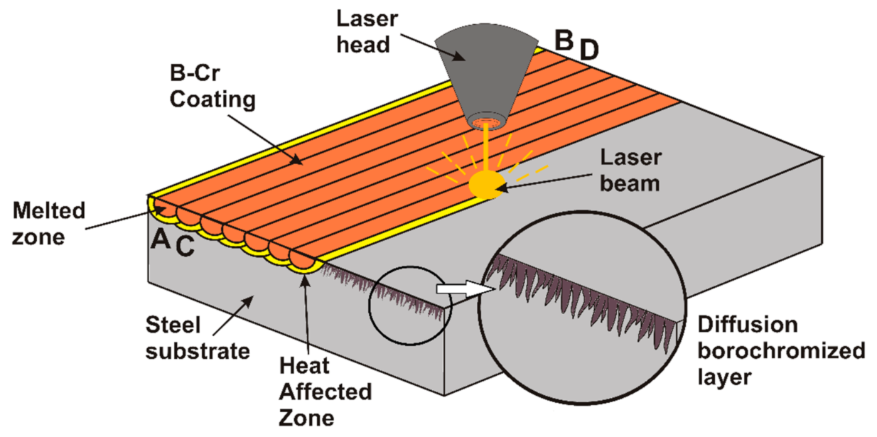
The B-Cr diffusion layers were produced at 950 °C in powder mixture consisting of boron carbides B4C, Fe-Cr, Al2O3, and AlF3. The boron source was B4C carbides (Sigma-Aldrich, Saint Louis, MI, USA), while the chromium source was Fe-Cr. Kaolin played the role of filler and aluminium fluoride was an activator. The diffusion borochromizing process was carried out in a furnace with a so-called open retort. Specimens were placed in the pipe retort together with powder mixture which was first preheated for 45 min from room temperature to set process temperature. Afterwards, the retort was annealed at 950 °C for 6 h. When the diffusion borochromizing process had ended, the retort was cooled in room temperature. Following diffusion process, the specimens were cleaned from powder residues and degreased with acetone. Then, the specimens thus prepared were subjected to laser processing. As a result of laser beam action, the diffusion borochromized layer was mixed with the tool steel substrate, and as a consequence the B-Cr coating formed. Laser remelting was performed on the 3 kW TruDiode 3006 diode laser (TRUMPF, Ditzingen, Germany). During these processes, three different laser beam powers of 600 W, 900 W, and 1200 W were applied. The diameter of the laser beam was 1 mm. The transverse electromagnetic mode in this laser machine was TEM00. The laser beam scanning speed for all specimens was constant at 3 m/min. The distance between the laser track axes was designed to obtain a level of overlap of 50%. Figure 1 shows the scheme of laser processing of diffusion borochromized layers. This process consisted of moving a laser beam from point A to B and then turning off the laser and returning from point B to point A. In next step, the laser head was transferred by a distance of 0.5 mm from point A to point C, and then (after a turn of the laser) from point C to D. This activity was repeated until the entire surface of the specimen was modified by laser beam.
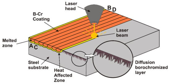
Figure 1.
Scheme of laser processing of diffusion borochromized layer.
Microstructure observations were carried out using an MIRA3 scanning electron microscope (TESCAN, Brno, Czech Republic) on cross sections of specimen perpendicular to the produced surface layers and coatings. Prior to observation, all specimens were ground with papers with grit from 80 to 2000, polished using diamond paste and aluminium oxide, and finally etched in 5% HNO3 solution. The scanning electron microscope was equipped with an EDS-UltimMax energy dispersive spectrometer (Oxford Instruments, High Wycombe, UK) and dedicated Aztec Energy Live Standard software.
The phase composition of the specimens was analyzed using an EMPYREAN PANalytical X-ray diffractometer (Malvern Panalytical Ltd., Malvern, UK) operating in the range of 2θ = 20°–90° by using Cu Kα radiation.
Microhardness tests were carried out on cross sections of coatings both along and on the border of laser tracks. Thanks to this it was found whether the obtained microhardness values are comparable on the entire newly formed layer produced and how the laser tracks affect each other. A FM-810 microhardness tester (Future-Tech, Kawasaki, Japan) equipped with a FT-Zero automatic indentation measuring software was used. Microhardness tests were made under indentation load of 100 G, while loading time was 15 s.
Corrosion resistance tests were carried out using ATLAS 1131 EU&IA device (At-las-Sollich, Rębiechowo, Poland) in 3.5% NaCl aqueous solution. The potentiodynamic method of anodic polarization curves was applied. The potentiodynamic measurements were performed at a 22 °C temperature at scanning speed of 1.0 mV/s. The reference electrode was a saturated calomel electrode, and the auxiliary electrode was a platinum electrode. Corrosion potential and corrosion current of analyzed specimens were determined in this study.
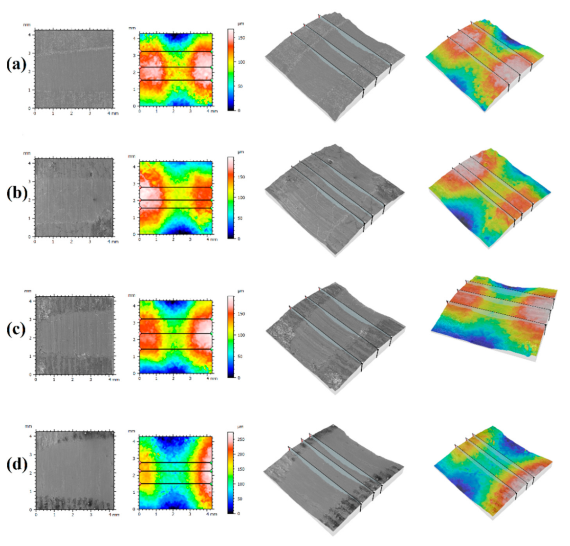
Wear resistance was tested on the plate-shaped specimens using an Amsler-type device (MBT, Poznan, Poland). The ring-shaped counter-specimens were made of CT90 tool steel after hardening from 780 °C in water and tempering at 180 °C for 1 h. Wear resistance tests were performed in dry friction conditions using the following parameters: rotation speed of counter-specimen 250 rev/min, load 98 N, and friction time 180 min. The mass loss of specimens was measured using the AS220.R2 analytical balance (RADWAG, Radom, Poland) after every 30 min of wear test. The 3D surface topography and roughness profiles reconstruction after wear tests were determined on SEM images with Mountains® SEM software manufactured by Digital Surf company (Digital Surf Headquarters, Besançon, France).
3. Results and Discussion
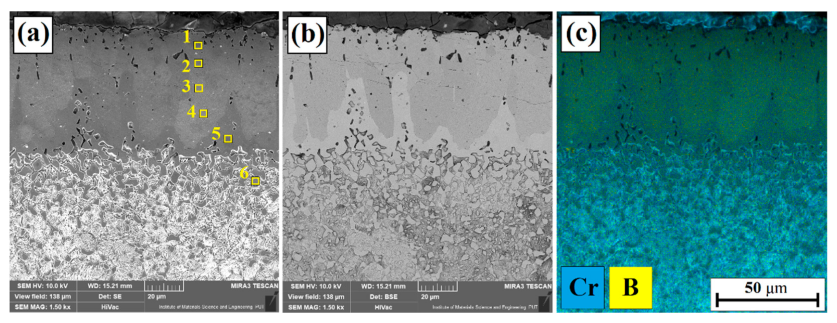
Figure 2 shows the microstructure of a borochromized diffusion layer produced from one pass on 145Cr6 steel. The obtained layer has a needle-like microstructure resembling a diffusion boronized layer. Figure 2a shows the borochromized layer in the contrast of reflected electrons (SE), while Figure 2b shows the contrast of secondary electrons (BSE) in which two characteristic areas in the diffusion layer are clearly visible. In order to check the distribution of chromium and boron in the borochromized layer, EDS mapping was performed (Figure 2c). In the brighter areas visible in Figure 2b, an increased chromium content was found. The chemical composition was also tested using the point method (Figure 2a) and the results are shown in Table 2. The obtained borochromized layer with a needle-like microstructure was approximately 60 µm. It can therefore be concluded that the thickness of the needle zone is similar to that following diffusion boronizing. Note, however, that in the case of borochromizing, the change in the surface layer was observed to a thickness of ~100 µm. It can be concluded that boron cementite is present below the needle zone. In the subsurface area of the diffusion borochromized layers, porosity was observed, and it also frequently occurred in the diffusion boronized layers. Other researchers also stated that the microstructure after chromizing of boronized layer had similar thickness of the coating after preboronizing. They found that the thin chromium-enriched layer is deposited on the outer layer of the columnar Fe2B grains [15].
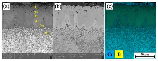
Figure 2.
Microstructure of diffusion borochromized layer: (a) SE image, (b) BSE image, and (c) EDS mapping.

The borochromized layer obtained was subjected to laser processing with varying laser beam powers, which resulted in the formation of B-Cr coatings. Figure 3, Figure 4 and Figure 5 show the microstructures of B-Cr coatings obtained as a result of the action of a diode laser beam with the power of 600, 900, and 1200 W, respectively. Three characteristic areas are distinguished on the cross section of the obtained samples: remelted zone (MZ), heat-affected zone (HAZ), and a substrate that did not receive a sufficient amount of heat and thus was not microstructurally altered. Mixing the components of the borochromized diffusion layer with the substrate material contributed to the enrichment of the remelted zone in boron and chromium. The amount of these elements depended on the power of the laser beam. As it increased, a deeper remelted zone was formed, and thus the iron content from the substrate increased. The heat affected zone clearly differs from the remelted zone, which is best seen in the BSE contrast. Both zones formed a parabolic melting line with the substrate, characteristic of laser processing.
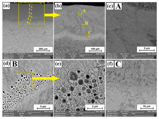
Figure 3.
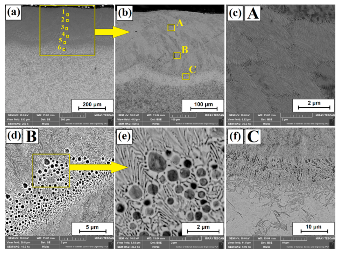
Microstructure of B-Cr coatings obtained using laser processing by laser beam power of 600 W: laser tracks (a), enlarging the laser track (b), upper area of remelted zone (c), middle area of remelted zone (d), enlarging of middle area of remelted zone (e), and boundary between the remelted zone and the heat-affected zone (f).
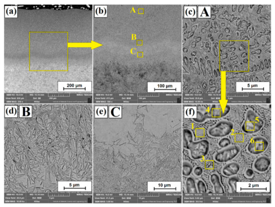
Figure 4.
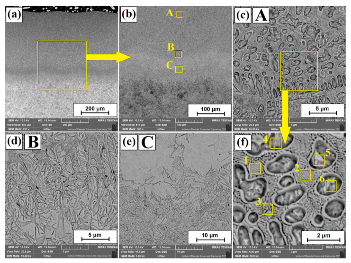
Microstructure of B-Cr coatings obtained using laser processing by laser beam power of 900 W: laser tracks (a), enlarging the laser track (b), upper area of remelted zone (c), boundary between the remelted zone and the heat-affected zone (d), heat-affected zone (e), and enlarging of upper area of remelted zone (f).
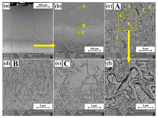
Figure 5.
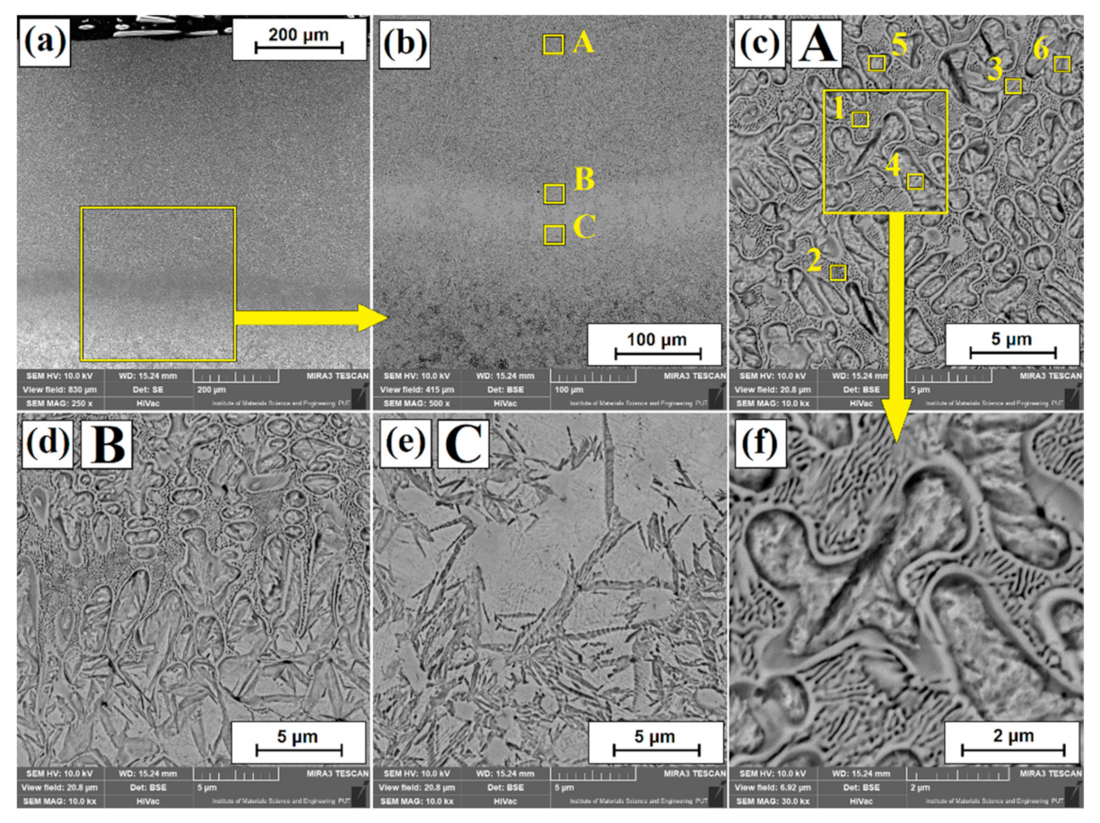
Microstructure of B-Cr coatings obtained using laser processing by laser beam power of 1200 W: laser tracks (a), enlarging the laser track (b), remelted zone (c), boundary between the remelted zone and the heat-affected zone (d), enlarging of heat-affected zone (e), and enlarging area of remelted zone (f).
Figure 5 shows the microstructure of the B-Cr coating produced as a result of laser modification of the diffusion borochromized layer using a laser beam power of 1200 W.
Generally, it can be concluded that the increase in laser beam power contributed to the intensification of structural changes, which is related to the greater amount of thermal energy adsorbed by the surface of the samples treated. The average depth of the remelted zone varied from 250 µm (600 W), through 400 µm (900 W) to 550 µm (1200 W). On the other hand, the total average depth of the obtained laser tracks was 303 µm (600 W), 536 µm (900 W) and 661 µm (1200 W), respectively. Figure 3 shows microstructures of B-Cr coatings obtained by laser modification with a laser beam power of 600 W. Figure 3b shows an enlargement of the area marked in Figure 3a. Overlapping of created laser tracks is clearly visible. A 50% overlapping was used, which resulted in coatings of nearly uniform thickness. Only minimal changes in thickness between the track axis and the overlap zone are visible.
In Figure 3b, the areas of laser tracks are marked with squares whose microstructure is shown in Figure 3c–f. The microstructure shown in Figure 3c is characterized by a lamellar structure that corresponds to a hypereutectic structure. Figure 3d, the enlarged area of which is shown in Figure 2e, shows the microstructure in the remelted zone, which contains the areas corresponding both to the hypereutectic and eutectic structure. Such a structure is the result of changes related to solidification rate of areas of variable chemical composition. When analyzing the B-Cr coating produced with the power of a 600 W laser beam, it can be concluded that it is characterized by a uniform microstructure in the entire area of the remelted zone. Figure 3f shows transition area between the remelted zone and the heat-affected zone, in which martensite needles are clearly visible. Their size increases as laser beam power increases. The coarse martensitic structure occurs in the area of the flat solidification front.
Figure 4 shows the microstructure of the B-Cr coating obtained by laser modification of the diffusion borochromized layer using a laser beam with a power equal to 900 W. The squares mark successively enlarged areas, i.e., Figure 4b shows the enlarged area of the laser track fragment from Figure 4a, and in this enlarged area in Figure 3a squares mark areas whose structures are shown enlarged in Figure 4c–e. It can be seen that when using such laser treatment parameters, the microstructure of the remelted zone is uniform (Figure 4c). The microstructure of the remelted zone is composed of Fe-α dendrites containing boron-chromium eutectic with martensite of lamellar structure (Figure 4c,f). Figure 4d shows the area of microstructure transition between the remelted zone and the heat-affected zone. Figure 4e shows the microstructure of the heat-affected zone where two characteristic areas could be distinguished. By observing this zone in contrast of reflected electrons, it is possible to identify both brighter regions, most likely containing alloy austenite, as also described in [40], as well as darker regions consisting of finer martensite needles with carbides originating from a steel substrate.
Laser tracks are shown in Figure 5a, where the area including the remelted zone and the heat-affected zone is marked with a square. This area is enlarged in Figure 5b. Figure 5c,f shows the microstructure of the remelted zone which is a boron-chromium eutectic with martensite. It can be seen that as a result of the parameters used, the share of eutectics in the remelted zone decreased, and the thickness of individual lamellae in the eutectic increased from 50 nm (600 W), 75 nm (900 W), to 95 nm (1200 W), respectively. The obtained eutectic structures are very similar to those in [41,42], where the authors analyzed the structure evolution upon nonequilibrium solidification of the bulk undercooled Fe-B system. Due to the slower heat dissipation associated with the use of high-power laser beam in the heat-affected zone, the martensite needles also grew (Figure 5d,e).
Table 2 summarizes the results of chemical composition measurements using the EDS method for the areas marked with squares in Figure 2, Figure 3, Figure 4 and Figure 5, i.e., both for diffusion borochromized layer and for B-Cr coatings produced by laser treatment. It can be observed that the boron content in the borochromized layer is 8.5 wt.%, which corresponds to the Fe2B phase. Moreover, it can be stated that the boron content is unchanged over the entire area of this zone. Below the needle-like zone of the diffusion borochromized layer, there is an increased content of boron, reaching approximately 4 wt.%, which approximately corresponds to the Fe3(C,B) boron cementite phase. The increased chromium content in the diffusion borochromized layers appears only in the areas between the needles and in the diffusion zone under the needle-like structure. Its compactness is approximately 3.5 wt.%. It can be assumed that complex phases of the (Fe, Cr)2B type were formed in the borochromized layers.
In the case of B-Cr coatings produced with a 600 W laser beam, the boron content on the cross section of the entire laser track was approximately 4.5 wt.%, while chromium was approximately 2 wt.% (Figure 3a). In the case of B-Cr coatings produced with the laser beam power of 900 and 1200 W, measurements were made in the dendritic and interdendritic regions (Figure 4f and Figure 5f, respectively). With the applied laser beam power of 900 W, the boron content in the area of the existing lamellar eutectic was approximately 4 wt.%, while in dendritic areas it decreased to the content of approximately 2 wt.%. In the interdendritic regions, the chromium content was approximately 2 wt.%, while in the area of the formed eutectic, it was approximately 1.5 wt.%. With the increase of laser beam power to 1200 W, a chromium content similar to that at 900 W was identified. The boron content, however, decreased only in the areas of eutectic appearance (Table 2).
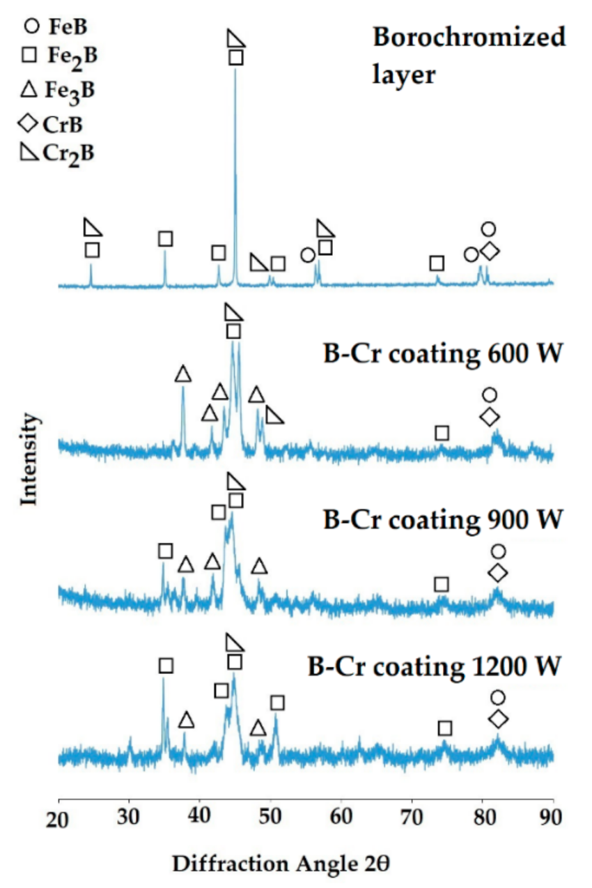
Figure 6 shows the results of X-ray analysis for the diffusion borochromized layer and for the B-Cr coatings. The Fe2B, Cr2B, FeB, and CrB phases were found in the diffusion borochromized layer. It can be assumed that complex phases of the (Fe, Cr)2B and (Fe, Cr) B type were also created, where in the case of iron and chromium, due to their similar atomic radii, there is a mutual exchange of these chemical elements. Note that the peaks originating from the M2B type phases, where M is iron or chromium, show the highest intensity. In ref. [15], it is considered that the Cr-rich layer is mainly composed of Cr2B, CrC, and Cr0.1Fe1.9 and it contains a large number of pores and cracks, indicating poor properties. In our case, no cracks were observed in the bright area enriched with chromium, but they occurred in the needle-like area (Figure 2). Laser modification of the diffusion borochromized layer reduced the intensity of most peaks. There is also an additional peak from the nonequilibrium phase of Fe3B iron borides. It can be observed that with the increase of laser beam power, the intensity of the peaks originating from the phase of the (Fe, Cr)2B type decreases. This is related to greater remelting and thus an increase in the amount of iron in the newly formed coating. The highest intensity and increased number of peaks of the obtained phases occur in the angular range of 35° to 55°. The resulting phases correspond to the phases that can be read from the Fe-Cr-B, Fe-CB, and Cr-BC phase equilibrium diagrams and correspond to the results of other researchers who take up this problem [43,44,45].
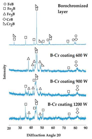
Figure 6.
X-ray diffraction results of diffusion borochromized layer and B-Cr coatings after laser processing.
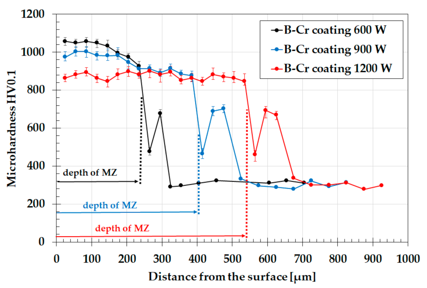
Microhardness of the diffusion borochromized layer ranged from approximately 1780 HV0.1 up to approximately 1740 HV0.1. Laser modification of this layer contributed to obtaining B-Cr coatings characterized by lower microhardness. However, note that these coatings were thicker and their hardness was much higher than the hardness of the substrate. Figure 7 shows microhardness profiles for B-Cr coatings produced at varying laser beam power values. The B-Cr coating produced with the laser beam power equal to 600 W was more than twice as thick as the diffusion layer. Its hardness in the remelted zone was 1060 HV0.1 to 930 HV0.1. The increase in laser beam power resulted in a decrease in microhardness. The microhardness in the remelted zone for coatings produced with the use of 900 W power was in the range of 1000 HV0.1 to 880 HV0.1, while for the power of 1200 W it was from 890 HV0.1 to 860 HV0.1. The microhardness of the cross-section of the coatings changed with increasing distance from the surface. In the area of the heat-affected zone, it was in the range of approximately 450 HV0.1 to approximately 700 HV0.1. In the substrate that was not affected by laser beam, the microhardness was approximately 300 HV01. In the upper part of the heat-affected zone, close to the border with the remelted zone, a reduced microhardness was observed, which was most likely caused by a slower cooling rate. As a result, a microstructure containing alloy austenite was obtained. Close to the steel substrate, martensite was part of the heat-affected zone, which in turn was associated with an increase in the cooling speed, i.e., the effect of the cold substrate material. The elements present there, i.e., chromium and boron, influenced the increase in hardness in the remelted zone. Microhardness measurements were made both in the axis and at the interface of the laser tracks at equal distances. There was no significant difference in microhardness between the measurements on the axis and on the border of the tracks.
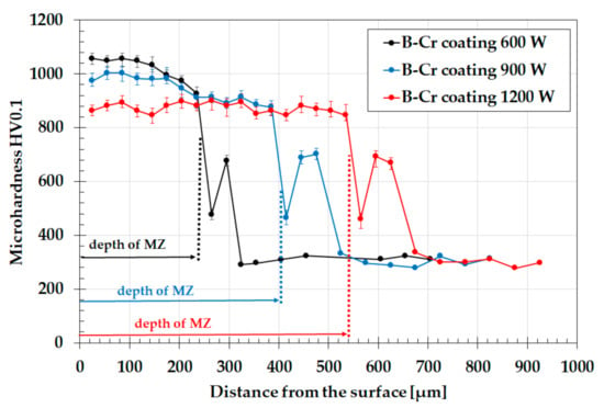
Figure 7.
Microhardness profiles of B-Cr coatings produced using laser processing of diffusion borochromized layers.
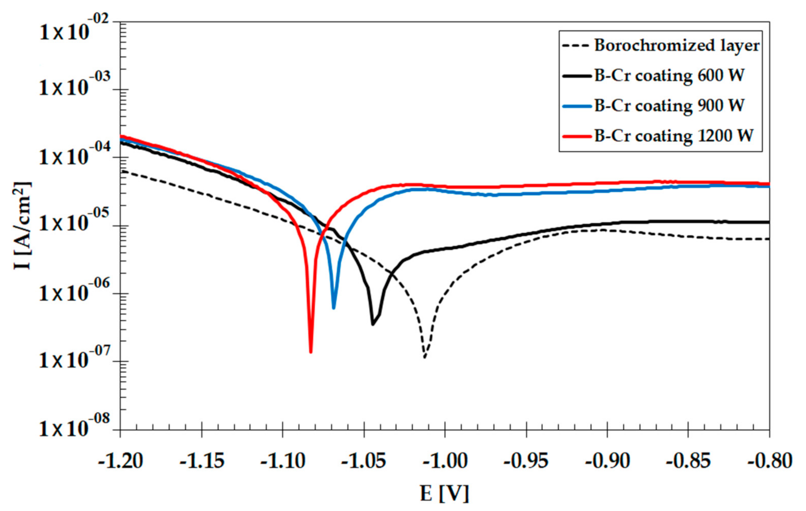
Figure 8 and Table 3 show the results of corrosion resistance studies of both the diffusion borochromized layer and the B-Cr coatings produced with the use of a laser beam. It was found that the B-Cr coatings are characterized by lower corrosion resistance than the diffusion layer. It is related to the increase of iron content in the subsurface zone. Iron has a lower corrosion resistance, and its high content in the coating causes the loss of corrosion resistance of the entire coating despite the fact that it contains corrosion-resistant chromium.
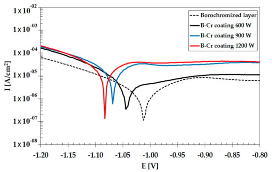
Figure 8.
Corrosion resistance of diffusion borochromized layer and B-Cr coatings.

Table 3.
Corrosion current and corrosion potential for diffusion borochromized layer and B-Cr coatings.
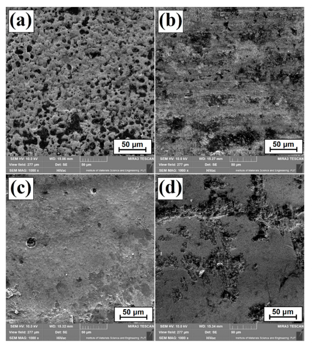
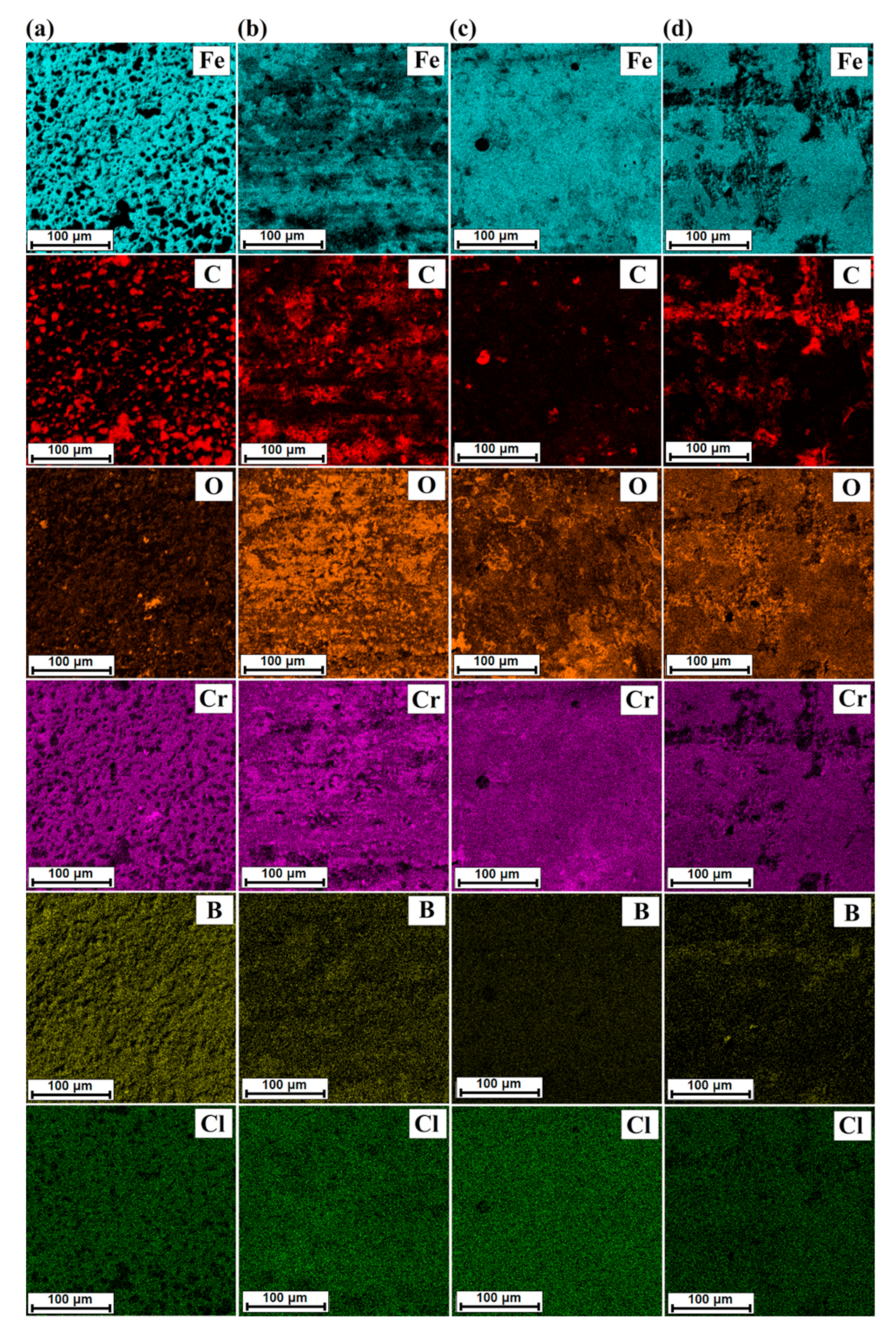
The morphology of the surface that was damaged during the potentiodynamic tests is shown in the photos taken after the corrosion tests (Figure 9), while the EDS results in the form of a distribution map of chemical elements are shown in Figure 10. As for borochromized layer, changes caused by the corrosive agent can be observed in the area of porosity. However, it was found that the share of oxygen on the observed surface is low, which proves good corrosion resistance. This is also confirmed by the results presented in Table 3. Application of laser remelting of the diffusion borochromized layer resulted in the enrichment of the subsurface zone with iron, which in turn contributed to the creation of numerous corrosion effects visible on sample surfaces. The network of cracks on the surface of the samples also contributed to reduced corrosion resistance. It was not observed in the cross section of the layer; however, it could be seen on the surface of the coating. Changes in laser beam power directly influenced chemical composition of the heat-affected zone. The changes in supplied energy influenced the greater or lesser presence of boron and chromium in the coating. Therefore, it can be concluded that the share of these elements in the remelted zone had a significant impact on the corrosion resistance.
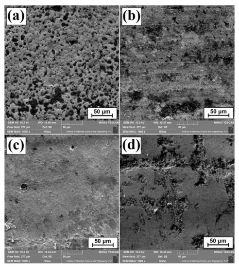
Figure 9.
Surface condition after corrosion resistance tests for (a) diffusion borochromized layer, (b) B-Cr coatings produced using 600 W, (c) B-Cr coatings produced using 900 W, and (d) B-Cr coatings produced using 1200 W.
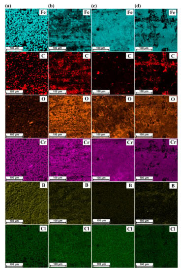
Figure 10.
EDS map of surface condition after corrosion resistance test for (a) diffusion borochromized layer, (b) B-Cr coatings produced using 600 W, (c) B-Cr coatings produced using 900 W, and (d) B-Cr coatings produced using 1200 W.
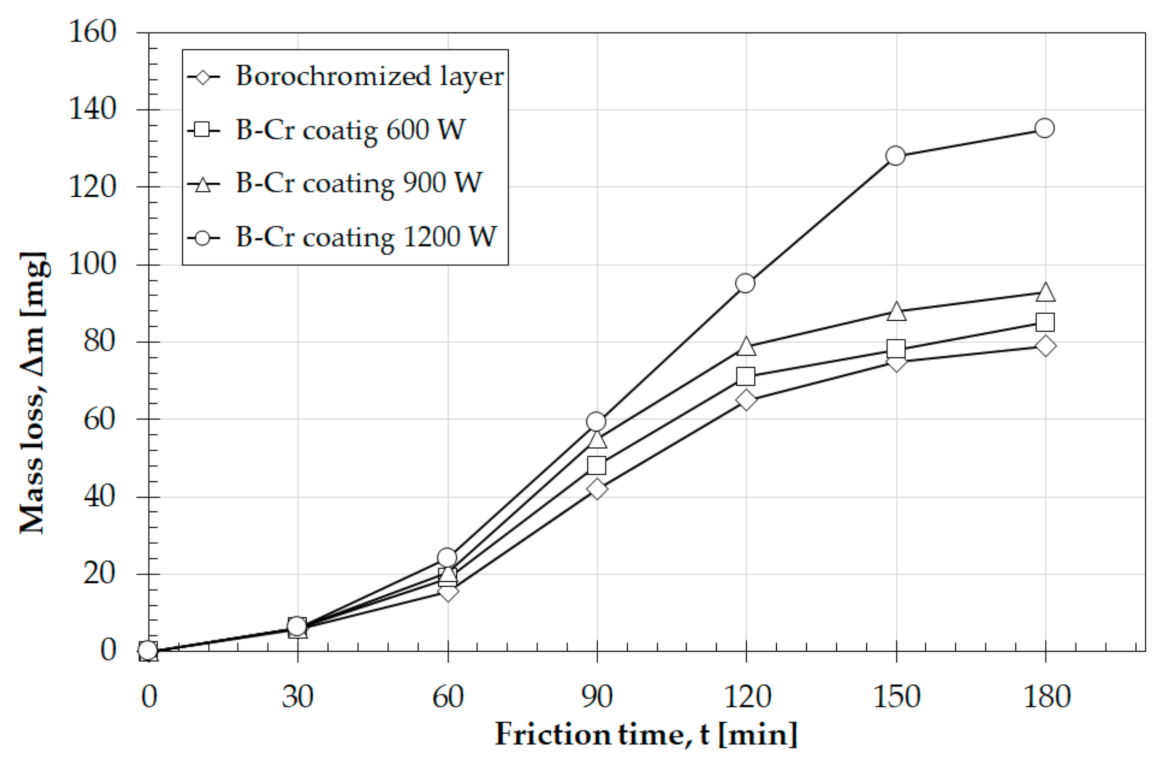
Figure 11 shows the results of wear resistance by friction of diffusion borochromized coatings and B-Cr coatings produced with a laser beam. The best wear resistance is observed in diffusion borochromized layer. However, it should be borne in mind that the diffusion layer produced is relatively thin compared to the B-Cr coatings produced by laser treatment. The B-Cr coating produced with a 600 W laser beam is characterized by a weight loss similar to that in the diffusion layer in the test. However, due to the aforementioned network of cracks, chipping or seizure may occur during the life span of such a coating. Therefore, it is recommended to sand the surface of the coating before putting it into operation in order to remove the network of cracks that does not penetrate into it. Such sanding would still be a common practice due to relatively high roughness of laser-produced coatings. As it is widely known, tools for metalworking, in particular plastic working, have precise dimensions and surface roughness. The use of higher laser beam power removes the unfavorable crack network, but this happens at the cost of reducing wear resistance by friction. Thus, the coating produced at a laser power of 1200 W is characterized by the highest wear.
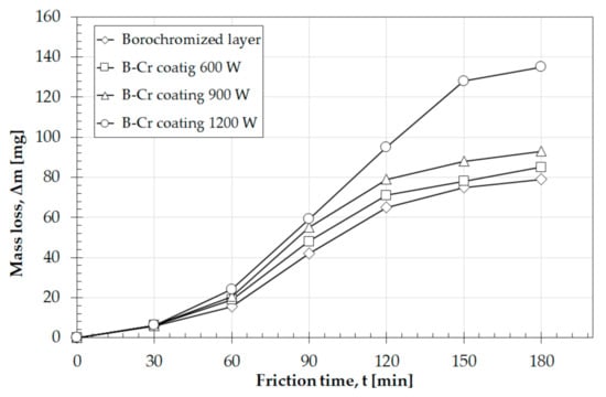
Figure 11.
Wear resistance of diffusion borochromized layer and B-Cr coatings produced using laser processing.
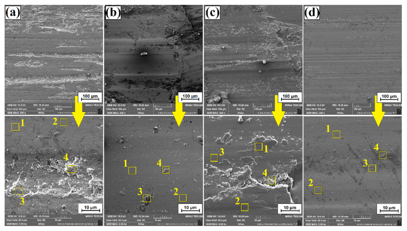
Figure 12 shows the SEM macroscopic images of sample surfaces taken after friction wear resistance tests. In the diffusion borochromized sample, a characteristic groove is visible. In samples with B-Cr coatings obtained using a laser beam power of 600 W and 900 W, micro-shearing can be observed. As there were also cracks on these surfaces, chipping is observed within them as well. In the case of the BCr coating produced at the power of 1200 W, the dominant mechanism is micro-shearing, which is indicated by a significant loss of material. In the areas where characteristic signs of wear caused by surface oxidation occur, the chemical composition was analyzed using the EDS method. The areas of analysis are marked in Figure 12, and the results are presented in Table 4. It can be seen that significant wear of the surface causes its exposure, and thus removal of oxygen. Significant oxidation of surfaces of the produced layers occurred in the areas of unevenness caused by grooving and micro-shearing.
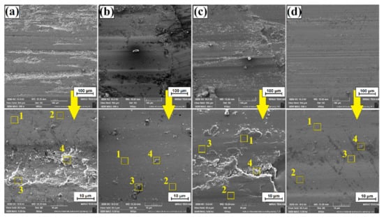
Figure 12.
Surface condition after wear resistance tests: (a) diffusion borochromized layer, (b) B-Cr coatings produced using 600 W, (c) B-Cr coatings produced using 900 W, and (d) B-Cr coatings produced using 1200 W.

Table 4.
Chemical composition (EDS) results after wear resistance tests.
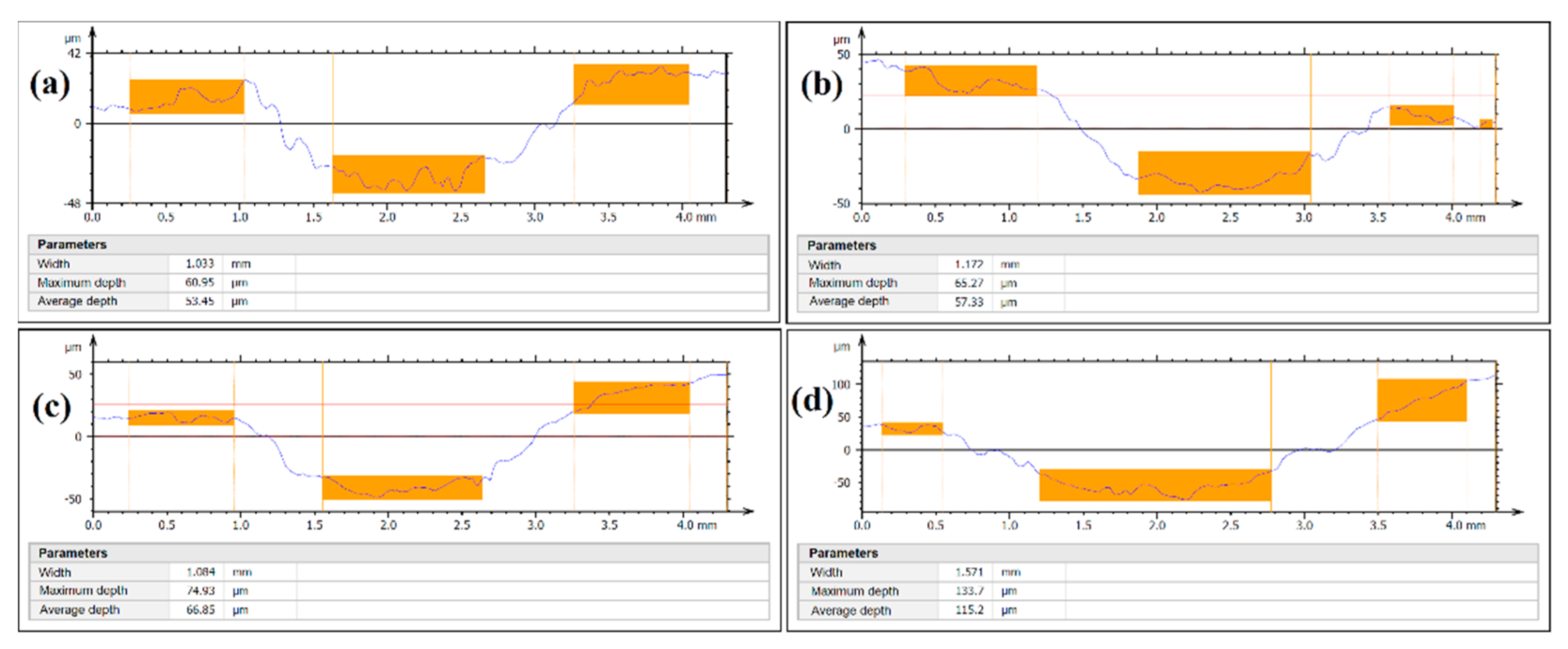
Figure 13 shows the surface topography of the samples following wear resistance tests. The first photo shows the SEM image necessary for 3D analysis of the image surface. The photos were taken at an angle of +4 and −4. Depending on their topographic contrast, a stereoscopic reconstruction of the produced borochromized layer and B-Cr coatings was performed. Figure 13 shows the spots where surface wear profiles were made. The data obtained on wear of the samples are summarized in Table 5. Selected parameters of 2D and 3D surface roughness were analyzed. From the group of 2D parameters, the parameters Ra (arithmetic mean profile deviation) and Rz (maximum height of roughness profile) were analyzed, while from the group of 3D parameters, Sa (arithmetic mean deviation of the height of surface unevenness from reference plane), Sq (mean square deviation of the height of surface unevenness from reference planes), and Sz (maximum height of 3D profile). The profiles showing wear traces after tribological tests are shown in Figure 14. The diffusion borochromized layer is characterized by the lowest width of the wear pattern and the shallowest depth. The largest wear trace was observed for the B-Cr coating produced with a laser beam power of 1200 W.
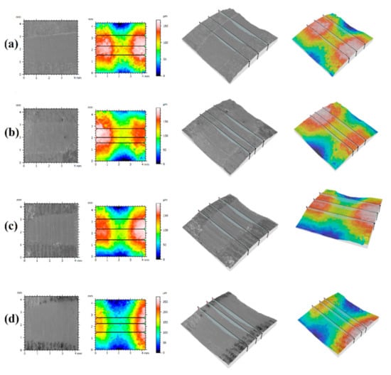
Figure 13.
Surface topography after wear resistance tests for (a) diffusion borochromized layer, (b) B-Cr coatings produced using 600 W, (c) B-Cr coatings produced using 900 W, and (d) B-Cr coatings produced using 1200 W.

Table 5.
Results of roughness parameters after wear resistance tests for diffusion borochromized layer and B-Cr coatings produced using laser processing.
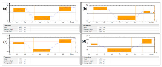
Figure 14.
Surface roughness profiles after wear resistance tests for (a) diffusion borochromized layer, (b) B-Cr coatings produced using 600 W, (c) B-Cr coatings produced using 900 W, and (d) B-Cr coatings produced using 1200 W.
4. Conclusions
The study analyzed changes in microstructure, chemical composition, microhardness, corrosion resistance, and wear resistance by friction of B-Cr surface layers obtained as a result of remelting the borochromized layer with a laser beam on 145Cr6 steel. Based on the studies conducted, the following conclusions were made.
The diffusion borochromized layer produced in one stage had a needle-like microstructure resembling the diffusion boronized layer, which, similarly to the boronized layer, was characterized by porosity in the subsurface zone.
As a result of laser beam activity, the diffusion borochromized layer was mixed with the substrate of the steel substrate. As a result, three characteristic areas were obtained: a remelted zone enriched with boron and chromium, a heat-affected zone, and a substrate that had not been changed by heat.
Microstructure of the remelted zone consisted of boron–chromium eutectic with martensite of lamellar structure. Its share decreased as a result of the applied laser processing parameters, and the thickness of individual lamellae in the eutectics increased from 50 nm (600 W), 75 nm (900 W), to 95 nm (1200 W), respectively.
It was found that too low laser beam power causes cracks in the newly formed B-Cr coating. On the other hand, too high laser beam power causes deep remelting, which results in the loss of microhardness.
The microhardness of the diffusion borochromized layer was approximately 1800 HV0.1. Laser modification of this layer contributed to obtaining B-Cr coatings characterized by lower microhardness, but the coatings were thicker and the hardness significantly exceeded the hardness of the substrate. Depending on the parameters used, the microhardness in the remelted zone ranged from approximately 1060 HV (600 W) to approximately 850 HV (1200 W). The newly formed B-Cr coatings had a favorable microhardness gradient between the layer and the substrate.
Corrosion resistance was slightly lower compared to diffusion borochromized layers. It was caused by appearance of cracks or deep remelting.
The B-Cr coating produced with a 600 W laser beam was characterized by a slight decrease in abrasion resistance compared to the diffusion borochromized layer. However, it should be emphasized that this coating was much thicker than diffusion borochromized layers. Too high laser beam power (1200 W) caused a significant decrease in wear resistance due to a high proportion of iron derived from the steel substrate.
Author Contributions
Conceptualization, A.B.; methodology, A.B. and D.B.; investigation, A.B., D.B., D.P., J.H., and A.M.; writing—original draft preparation, A.B.; writing—review and editing, A.B. and D.B; visualization, A.B. and D.B. All authors have read and agreed to the published version of the manuscript.
Funding
The presented research results were funded by grants for education allocated by the Ministry of Science and Higher Education in Poland.
Institutional Review Board Statement
Not applicable.
Informed Consent Statement
Not applicable.
Data Availability Statement
Data available on request.
Conflicts of Interest
The authors declare no conflict of interest.
References
- Sochacka, P.; Miklaszewski, A.; Jurczyk, M. Development of β-type Ti-x at.% Mo alloys by mechanical alloying and powder metallurgy: Phase evolution and mechanical properties (10 ≤ x ≤ 35). J. Alloy Compd. 2019, 776, 370–378. [Google Scholar] [CrossRef]
- Li, N.; Liu, W.; Wang, Y.; Zhao, Z.; Yan, T.; Zhang, G.; Xiong, H. Laser additive manufacturing on metal matrix composites: A review. Chin. J. Mech. Eng. 2021, 34, 38. [Google Scholar] [CrossRef]
- Ignaszak, Z.; Hajkowsk, I.J.; Popielarski, P. Mechanical properties gradient existing in real castings taken into account during design of cast components. Defect Diffus. Forum 2013, 334–335, 314–321. [Google Scholar] [CrossRef]
- Wojciechowski, S.; Przestacki, D.; Chwalczuk, T. The evaluation of surface integrity during machining of Inconel 718 with various laser assistance strategies. MATEC Web Conf. 2017, 136, 01006. [Google Scholar] [CrossRef]
- Czerwinski, F. Heat Treatment: Conventional and Novel Applications; IntechOpen: London, UK, 2012. [Google Scholar] [CrossRef]
- Hajkowski, J.; Popielarski, P.; Ignaszak, Z. Cellular automaton finite element method applied for microstructure prediction of aluminium casting treated by laser beam. Arch. Foundry Eng. 2019, 19, 111–118. [Google Scholar]
- Burakowski, T.; Wierzchon, T. Surface Engineering of Metals. Principles, Equipment, Technologies; CRC Press: Boca Raton, FL, USA, 2020; ISBN 9780367400125. [Google Scholar]
- Krukovich, M.G.; Prusakov, B.A.; Sizov, I.G. Plasticity of Boronized Layers; Springer Series in Materials Science; Spinger: Berlin/Heidelberg, Germany, 2016; p. 237. ISBN 978-3-319-40012-9. [Google Scholar]
- Kulka, M.; Pertek, A. Gradient formation of boride layers by borocarburizing. Appl. Surf. Sci. 2008, 254, 5281–5290. [Google Scholar] [CrossRef]
- Balandin, Y.A. Surface hardening of die steels by diffusion boronizing, borocopperizing, and borochromizing in fluidized bed. Met. Sci. Heat Treat. 2005, 47, 103–105. [Google Scholar] [CrossRef]
- Ouladsaad, S.; Allaoui, O.; Daas, A. Boro-aluminizing of XC38 steel. Indian J. Chem. Technol. 2019, 26, 239–243. [Google Scholar]
- Arendar, L.A.; Vasyliv, K.B.; Shyrokov, V.V. Influence of load on the deformation of the surface layers of steels with a boron–chromium coating. Mater. Sci. 2012, 47, 807–812. [Google Scholar] [CrossRef]
- Bartkowska, A.; Bartkowski, D.; Piasecki, A. Effect of diffusion borochromizing on microstructure, microhardness and corrosion resistance of tool steel with different carbon content. J. Achiev. Mater. Manuf. Eng. 2017, 80, 49–55. [Google Scholar] [CrossRef]
- Grachev, S.V.; Mal’tseva, L.A.; Mal’tseva, T.V.; Kolpakov, A.S.; Dmitriev, M.Y. Boronizing and borochromizing in a vibrofluidized bed. Met. Sci. Heat Treat. 1999, 41, 465–468. [Google Scholar] [CrossRef]
- Hu, J.; Zeng, J.; Yang, Y.; Yang, X.; Li, H.; Guo, N. Microstructures and wear resistance of boron-chromium duplex-alloyed coatings prepared by a two-step pack cementation proces. Coatings 2019, 9, 529. [Google Scholar] [CrossRef]
- Zeng, J.; Hu, J.; Yang, X.; Xu, H.; Li, H.; Guo, N. Evolution of the microstructure and properties of pre-boronized coatings during pack-cementation chromizing. Coatings 2020, 10, 159. [Google Scholar] [CrossRef]
- Fang, H.M.; Xu, F. Research on properties of Fe-based powder metallurgy material strengthened by boriding. Strength Mater. 2020, 52, 621–626. [Google Scholar] [CrossRef]
- Ivanov, Y.F.; Gromov, V.E.; Romanov, D.A.; Ivanova, O.V.; Teresov, A.D. Liquid-phase boriding of high-chromium steel. Steel Transl. 2020, 50, 452–459. [Google Scholar] [CrossRef]
- Mahdavi, A.; Medvedovski, E.; Mendoza, G.L.; McDonald, A. Corrosion resistance of boronized, aluminized, and chromized thermal diffusion-coated steels in simulated high-temperature recovery boiler conditions. Coatings 2018, 8, 257. [Google Scholar] [CrossRef]
- Triani, R.M.; De Assis Gomes, L.F.; Neto, A.L.; Totten, G.E.; Casteletti, L.C. Production and characterization of boride and carbide layers on AISI 15B30 steel. JMEPEG 2020, 29, 3534–3541. [Google Scholar] [CrossRef]
- Uzun, Y.; Kovacı, H.; Yetim, A.F.; Çelik, A. Effect of boronizing on the structural, mechanical and tribological properties of CoCrW dental alloy produced by selective laser melting. Ind. Lubr. Tribol. 2019, 71, 348–356. [Google Scholar] [CrossRef]
- Hosmani, S.S.; Kuppusami, P.; Goyal, R.K. An Introduction to Surface Alloying of Metals; Springer: Berlin/Heidelberg, Germany, 2014. [Google Scholar] [CrossRef]
- Lin, N.; Xie, F.; Zhou, J.; Zhong, T.; Wu, X.; Tian, W. Microstructures and wear resistance of chromium coatings on P110 steel fabricated by pack cementation. J. Cent. South Univ. Technol. 2010, 17, 1155–1162. [Google Scholar] [CrossRef]
- Dong, Z.; Zhou, T.; Liu, J.; Zhang, X.; Shen, B.; Hu, W.; Liu, L. Cavitation erosion behaviors of surface chromizing layer on 316L stainless steel. Ultrason. Sonochemistry 2019, 58, 104668. [Google Scholar] [CrossRef]
- Dong, Z.; Zhou, T.; Liu, J.; Zhang, X.; Shen, B.; Hu, W.; Liu, L. Effects of pack chromizing on the microstructure and anticorrosion properties of 316L stainless steel. Surf. Coat. Technol. 2019, 366, 86–96. [Google Scholar] [CrossRef]
- Gopalakrishnan, P.; Shankar, P.; Subba Rao, R.V.; Sundar, M.; Ramakrishnan, S.S. Laser surface modification of low carbon borided steels. Scripta Mater. 2001, 44, 707–712. [Google Scholar] [CrossRef]
- Kulka, M.; Pertek, A. Laser surface modification of carburized and borocarburized 15CrNi6 steel. Mater. Charact. 2007, 58, 461–470. [Google Scholar] [CrossRef]
- Steen, W.M.; Mazumder, J. Laser Material Processing, 4th ed.; Springer: London, UK, 2010. [Google Scholar] [CrossRef]
- Bartkowska, A.; Bartkowski, D.; Jurči, P. Laser cladding process of Fe/WC metal matrix composite coatings on low carbon steel using Yb: YAG disk laser. Opt. Laser Technol. 2021, 136, 106784. [Google Scholar] [CrossRef]
- Major, B. Laser processing for surface modification by remelting and alloying of metallic systems. In Materials Surface Processing by Directed Energy Techniques; Paleau, Y., Ed.; Elsevier: New York, NY, USA, 2006. [Google Scholar]
- Bartkowska, A.; Jurči, P.; Hudáková, M.; Bartkowski, D.; Kusý, M.; Przestacki, D. Effect of diode laser beam fluence on change in microstructure, microhardness and phase composition of FeB-Fe2B layers produced on Vanadis-6 steel. Arch. Metall. Mater. 2018, 63, 791–800. [Google Scholar]
- Bartkowska, A.; Swadźba, R.; Popławski, M.; Bartkowski, D. Microstructure, microhardness, phase analysis and chemical composition of laser remelted FeB-Fe2B surface layers produced on Vanadis-6 steel. Opt. Laser Technol. 2016, 86, 115–125. [Google Scholar] [CrossRef]
- Bartkowska, A.; Bartkowski, D.; Piasecki, A.; Jurči, P. Influence of laser cladding parameters on microstructure, microhardness, chemical composition, wear and corrosion resistance of Fe-B composite coatings reinforced with B4C and Si particles. Coatings 2020, 10, 809. [Google Scholar] [CrossRef]
- Bartkowska, A.; Bartkowski, D.; Popławski, M.; Przestacki, D. Microstructure, microhardness, corrosion and wear resistance of B, Si and B-Si coatings produced on C45 steel using laser processing. Metals 2020, 10, 792. [Google Scholar] [CrossRef]
- Bartkowska, A.; Bartkowski, D.; Popławski, M.; Piasecki, A.; Przestacki, D.; Miklaszewski, A. Microstructure, microhardness, corrosion resistance and chemical composition of Mo, B and Mo-B coatings produced using laser processing. Materials 2020, 13, 3249. [Google Scholar] [CrossRef]
- Joo, Y.-A.; Yoon, T.-S.; Park, S.-H.; Lee, K.-A. Microstructure and compression properties of Fe-Cr-B alloy manufactured using laser metal deposition. Arch. Metall. Mater. 2018, 63, 1459–1462. [Google Scholar] [CrossRef]
- Idriss, A.N.M.; Mridha, S.; Baker, T.N. Laser and GTAW torch processing of Fe-Cr-B coatings on steel. Part II—Microstructure and hardness. Mater. Sci. Technol. 2015, 31, 355–360. [Google Scholar] [CrossRef]
- Lawrence, J.R.; Waugh, D. Laser Surface Engineering: Processes and Applications, 1st ed.; Woodhead Publishing Series in Metals and Surface Engineering Book 65; Woodhead Publishing: Sawston, UK, 2014. [Google Scholar]
- Młynarczak, A.; Borecki, P.; Bartkowski, D. Microstructure and corrosion resistance of chromed diffusion layers and chrome plated galvanic coatings, before and after CO2 laser modification. Inżynieria Materiałowa—Mater. Eng. 2013, 3, 185–187. [Google Scholar]
- Chaus, A.S.; Maksimenko, A.V.; Fedosenko, N.N.; Čaplovič, L.; Myshkovets, V.N. Formation of structure of an annealed high-speed steel upon laser surface melting. Phys. Met. Metallogr. 2019, 120, 371–377. [Google Scholar] [CrossRef]
- Yang, C.; Liu, F.; Yang, G.; Zhou, Y. Structure evolution upon non-equilibrium solidification of bulk undercooled Fe–B system. J. Cryst. Growth 2009, 311, 404–412. [Google Scholar] [CrossRef]
- Lentz, J.; Röttger, A.; Theisen, W. Mechanism of the Fe3(B,C) and Fe23(C,B)6 solid-state transformation in the hypoeutectic region of the Fe-C-B system. Acta Mater. 2016, 119, 80–91. [Google Scholar] [CrossRef]
- Homolová, V.; Čiripová, L. Experimental investigation of isothermal section of the B-Cr-Fe phase diagram at 1353 K. Adv. Mater. Sci. Eng. 2017, 2017, 2703986. [Google Scholar] [CrossRef]
- Rogl, P. Cr-B-C (Chromium-Boron-Carbon). In Phase Diagrams of Ternary Metal-Boron-Carbon Systems; Effenberg, G., Ed.; ASM International: Russel Township, OH, USA, 1998; pp. 36–52. [Google Scholar]
- Brykov, M.N.; Petryshynets, I.; Džupon, M.; Kalinin, Y.A.; Efremenko, V.G.; Makarenko, N.A.; Pimenov, D.Y.; Kováč, F. Microstructure and properties of heat affected zone in high-carbon steel after welding with fast cooling in water. Materials 2020, 13, 5059. [Google Scholar] [CrossRef] [PubMed]
Publisher’s Note: MDPI stays neutral with regard to jurisdictional claims in published maps and institutional affiliations. |
© 2021 by the authors. Licensee MDPI, Basel, Switzerland. This article is an open access article distributed under the terms and conditions of the Creative Commons Attribution (CC BY) license (https://creativecommons.org/licenses/by/4.0/).

