Abstract
Polylactic acid (PLA) is one of the most extensively used biodegradable aliphatic polyester produced from renewable resources, such as corn starch. Due to its qualities, PLA is a leading biomaterial for numerous applications in medicine as well as in industry, replacing conventional petrochemical–based polymers. The purpose of this paper is to highlight the fracture behavior of pure PLA specimens in comparison with PLA particle insertions, (copper, aluminum and Graphene), after evaluation the mechanical properties, as well as the influence of filament angle deposition on these properties. In order to check if the filling density of the specimen influences the ultimate tensile stress (UTS), three different filling percentages (60%, 80%, and 100%) have been chosen in the experimental tests. A hierarchy concerning elongation / fiber heights after tensile testing was done. So, the highest elongation values were for simple PLA (about 4.1%), followed by PLA + Al insertion (3.2%–4%), PLA + graphene insertion (2.6%–4%) and the lowest values being for PLA with copper insertion (1.8%–2.7%). Regarding the fiber heights after fracture, the hierarchy was: the highest values was for PLA, then PLA + Al, PLA + grapheme and PLA + Cu. Finally, a correlation between fracture surfaces appearance and mechanical properties were established, being formulated the mechanism of fracture in according with filament angle deposition. Also, it was proposed a new method of evaluation of the fractured surface by measuring the dimensions of the filaments after printing Fused Deposition Modeling (FDM) and tensile testing.
1. Introduction
Polylactic acids (PLA) are materials generally synthesized from agricultural resources, such as corn or sugar cane. PLA is a polyester obtained from lactic acid structure blocks [1]. PLA is named “thermoplastic” polyester. A significant helpful property about thermoplastics is that these materials can be warmed to their softening point, cooled, and warmed again without rapid degradation [2]. The world is becoming aware of the dangers of natural degradation, but current models are based on the use of reinforced biodegradable materials to increase their mechanical properties [3]. Currently, the use of polylactic acid has seen an increase in the consumer market because it is an alternative, necessary, and beneficial method to reduce the problems due to solid waste left behind by oil-based plastics [2]. PLA has great mechanical properties and biocompatibility, and has an easy-to-use manufacturing process. PLA presents a high elasticity and is not a hard material. PLA resistance can be increased by the copolymerization process [4]. A major disadvantage of PLA is its rapid degradation. There is a new trend for green polymers due to the fact that they offer a beneficial alternative to financially sustainable development and contributes to the preservation of used materials, thus reducing pollution and the amount of environmentally harmful waste [5]. Lactic acid is the most well-known natural carboxylic acid [3]. Initially, lactic acid was a petrochemically obtained material [3]. PLA has rough properties comparable with those of traditional thermoplastic materials [4]. The most used classes of PLA are copolymers of poly L-lactic acid (PLLA) and poly D, L-lactic acid (PDLLA) [6]. In the manufacturing condition of 3D printing items, polylactic acid (PLA) is a material used more significantly than ABS, nylon, and different mixes of polycarbonate. It is a material utilized for 3D printing with FDM (Fused Deposition Modeling) innovation [2]. PLA-based materials have a glass transition temperature between (60–70 °C), and are ideal for use in FDM. The operating principle of FDM follows the next steps: the extrusion material is melted and brought to a high viscosity and forced through a nozzle to form a wire with a diameter smaller than the diameter of the input wire, which will solidify quickly after extrusion [2]. The incoming filament will be liquefied at a temperature where the filament changes state. The diameter of the filament obtained from the extrusion will remain constant if the movement of the printer on the surface is set at a constant speed. The properties of polylactic acid depend on isomerism, melting temperature, and cooling time [7,8]. In addition, an important property of polymers is crystallinity [9]. The properties of polylactic acid (PLA) such as hardness, elasticity, tensile strength, stiffness, and melting points are influenced by crystallinity and are of interest for its use in various applications.
Three-dimensional printing filament is created using a process of heating, extruding, and cooling plastic to transform nurdles into the finished product. Unlike a 3D printer, the filament is pulled rather than pushed through the nozzle during its formation, and the diameter of the filament is defined by the process that takes place after the plastic has been heated rather than the diameter of the extruder nozzle. A different force and velocity is applied to the filament as it is pulled out of the extruder in order to define its width, and it is most commonly 1.75 or 2.85 mm in diameter [10,11].
In the last decade, some researches are concerning with the possibilities of improving the performance of biomaterials, either by proteins adsorption [12], or by particles insertion. Engineers and scientists have capitalized some applications with the advantages of PLA [13]: environmentally friendly, ease to produce, recyclable, compostable, biocompatible, and some of them being non-carcinogenic [14]. PLA may be derived from renewable resources such as carbon dioxide, wheat, corn, and rice. PLA’s degradation products are also non-toxic to humans and the environment. The production of PLA uses 25%–55% less energy than that of petrol-based polymers [14]. The ease of PLA production is due to inexpensive and widely available source materials. PLA has been approved by the FDA for direct contact with biological fluids. A lot of studies [15,16,17,18,19] take into consideration the mechanical behavior of different printing PLA materials. Ezeh [20] quantitatively reviewed our understanding of the fatigue behavior of additively manufactured (AM) polylactide (PLA), revealing the fact that AM PLA is characterized by a fatigue performance similar to the one of manufactured PLA using conventional and well-established technologies.
DeStefano summarized all the applications of PLA as biomaterial [21]. PLA has demonstrated instrumental importance as a three-dimensionally (3D) printable biopolymer, which has further been bolstered by its role during the Coronavirus Disease of 2019 (COVID-19) global pandemic. As an abundant filament, PLA has created desperately needed personal protective equipment (PPE) and ventilator modifications. As polymer chemistry researches continue to improve, the applications and continued efficacy of PLA-based modalities will also improve. Concerning the possible applications of PLA with different particle insertions, the most studied researches are considering aluminum, i.e., PLA/Al2O3 for nanoscaffolds, biological bone, or dental resins [22,23,24,25,26]. Several studies consider PLA with particle copper insertions [27,28,29] for intrauterine coil, used for birth control and emergency contraception. In the last decade [30,31,32,33,34], the effect of carbon-based polypropylene nanocomposites was studied for different applications, with medical applications being one among them. Graphene-based nanomaterials are fast emerging as “two-dimensional wonder materials” due to their unique structure, excellent mechanical, optical, and electrical properties, and have been exploited in electronics and other fields. Emerging trends show that their exceptional properties can be exploited for biomedical applications, especially in drug delivery and tissue engineering.
The present research has a high degree of novelty and comes as a continuation of the researches in the field of fracture behavior of PLA versus PLA with different particle insertion. One may remark that there are no data concerning the mechanism of fracture, or data concerning the dimensions of fibers post fracture used for 3D Fused Deposition technology, and mechanical properties of PLA. So, the purpose of this paper is to highlight the fracture behavior of pure PLA specimens in comparison with particles insertion PLA (with copper, aluminum, and/or graphene powder), after evaluation of the mechanical properties, as well as the influence of filament angle deposition or filling percentage on these properties. In order to check if the filling density of the specimen influences the ultimate tensile stress (UTS), three different filling percentages (60%, 80%, and 100%) have been chosen in the experimental tests.
2. Materials and Methods
In this study, different types of filaments were used for manufacturing: PLA (polylactic acid), PLA with copper particles insertion, PLA with aluminum particles insertion, and PLA with graphene particles insertion. PLA thermoplastic polyester filament used for 3D printing using the Fused Deposition Modeling (FDM) method is provided by Poland’s (Mikołow) Devil Design, for simple PLA, from SainSmart (Canton, China), form PLA with insertion of particles of copper and aluminum, and from FILOALFA for PLA with insertion of particles graphene. These filaments were used to print bone-shaped specimens. The specimens were printed taking into account the ASTM D638 standard [10] and using a CREALITY 3D printer (Shenzhen, China). Concerning the printing methods, three different filling densities of the specimen were used: 60%, 80%, and 100%. In order to evaluate the mechanical characteristics of the specimen as a function of stacking sequence of the layer’s deposition, two cross different layer orientations (±45°and ±60°) have been taken into account. All specimens, regardless the material type, were printed at a same extrusion temperature in the range 180–210 °C, and the heating platform heated to a temperature in the range 20–60 °C. The manner of printing the sample is shown in Figure 1.
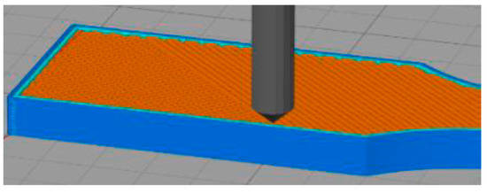
Figure 1.
Layer deposition [35].
Specimens were tested in tension on a universal testing machine—INSTRON 8800 (Norwood, Massachusetts, MA, USA). The test speed was 1 mm/min. This machine has a capacity of up to 100 kN and is equipped with hydraulic grips (from ambient temperature up to 1000 °C). This machine is also equipped with advanced devices: Digital Numeric Controller, Software (TrendTracker v1.11) Console, and Dynacell Single Load INSTRON Cells [36]. For each experiment, 5 samples were used in the same conditions. The geometrical characteristics of the sample are shown in Figure 2.
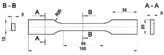
Figure 2.
Geometrical characteristics of specimen, (mm).
The aspects of the fractured samples were appreciated by structural analysis made both on stereomicroscope type Olympus SZX7 (Bucharest, Romania), equipped with Quick Photo Micro 2.2 soft image used for capturing, processing, and performing measurements on images up to 300× [37] and SEM analysis on PHILIPS microscope type XL-30-ESEM TMP (Eindhoven, Netherlands).
Structural analysis was made both in transversal and longitudinal cross section, in order to formulate correlations between printing characteristics and the manner of fracture, also depending on the type of insertions.
3. Results and Discussion
After performing the mechanical tests, the results are summarized in Figure 3.
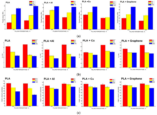
Figure 3.
Tensile stress (a), elongation (b) and fiber heights (c) versus different 3D printing characteristics of the PLA with or without particle insertions (Cu, Al, graphene).
As presented in Figure 3a, the lowest values of the ultimate strength are the specimens without inserts, in the order of PLA, followed by PLA with particle aluminum inserts, PLA with particle copper inserts, and PLA with particle graphene inserts. Another item regardless the chemical composition of the specimens-the same type of evolution of the values of mechanical strengths-can be noticed: they increase slightly with the increase of the thread deposition angle (from 45° or 60°) and decrease with the increase of the interior fill percentage (from 60% to 80% and 100%).
As observed in Figure 3b, the largest elongations are recorded in the specimens without insertions, i.e., in the PLA. Regardless the filling angle (45° or 60°), or the filling percentage (60%, 80%, or 100%), a hierarchy in descending order starting with simple PLA, followed by PLA with aluminum inserts, followed by PLA with particle graphene, and finally PLA specimens with copper inserts displaying the lowest values was observed.
In all specimens, regardless the chemical composition, the same type of evolution is observed, i.e., the increase of the interior fill percentage (from 60%, to 80% or to 100%) or the increase of the thread deposition angle (from 45° or 60°) as the elongation decreases.
The evolution of the fiber heights of all the samples (Figure 3c) irrespective of their chemical composition may approximately have the same trend: increasing the angle degree or filling percentage lead to a decrease of the fiber height. It means that the ductility potential of the fiber can increase due to these printing parameters. The values of fiber height with different insertions are higher than the simple PLA, in all conditions. A hierarchy may be made: the highest values of the fiber heights are for PLA + Al, then PLA + graphene, and PLA + Cu.
The qualitative and quantitative fractographic analysis performed in both longitudinal and transversal cross section of the test specimens after stereomicroscopic analysis allowed the realization of correlations among the fiber size, the fiber inclination angle, and the type of reinforcing element (Cu, Al, graphene), as given in Figure 4, Figure 5, Figure 6, Figure 7, Figure 8 and Figure 9.
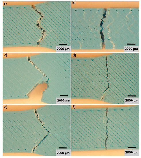
Figure 4.
Macrostructural aspect at stereomicroscope of polylactic acid material, in longitudinal cross section, with different 3D printing parameters: (a) 60% interior fill percentage and 45° thread deposition; (b) 60% interior fill percentage and 60° thread deposition; (c) 80% interior fill percentage and 45° thread deposition; (d) 80% interior fill percentage and 60° thread deposition; (e) 100% interior fill percentage and 45° thread deposition; (f) 100% interior fill percentage and 60° thread deposition.
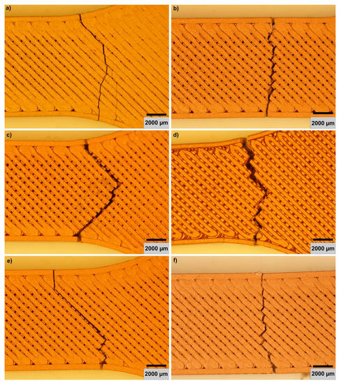
Figure 5.
Macrostructural aspects at stereomicroscope of polylactic acid material with copper particles in longitudinal cross section, with different 3D printing parameters: (a) 60% interior fill percentage and 45° thread deposition; (b) 60% interior fill percentage and 60° thread deposition; (c) 80% interior fill percentage and 45° thread deposition; (d) 80% interior fill percentage and 60° thread deposition; (e) 100% interior fill percentage and 45°thread deposition; (f) 100% interior fill percentage and 60° thread deposition.
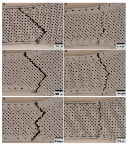
Figure 6.
Macrostructural aspects at stereomicroscope of polylactic acid material with aluminum particles in longitudinal cross section, with different 3D printing parameters: (a) 60% interior fill percentage and 45° thread deposition; (b) 60% interior fill percentage and 60° thread deposition; (c) 80% interior fill percentage and 45° thread deposition; (d) 80% interior fill percentage and 60° thread deposition; (e) 100% interior fill percentage and 45° thread deposition; (f) 100% interior fill percentage and 60° thread deposition.
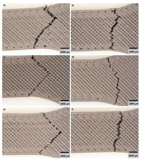
Figure 7.
Macrostructural aspects at stereomicroscope of polylactic acid material with graphene particles in longitudinal cross section, with different 3D printing parameters: (a) 60% interior fill percentage and 45° thread deposition; (b) 60% interior fill percentage and 60° thread deposition; (c) 80% interior fill percentage and 45° thread deposition; (d) 80% interior fill percentage and 60° thread deposition; (e) 100% interior fill percentage and 45° thread deposition; (f) 100% interior fill percentage and 60° thread deposition.
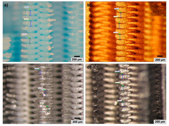
Figure 8.
Macrostructural aspect at stereomicroscope of experimental samples in transversal cross section, with 60% interior fill percentage and 45° thread deposition: (a) polylactic acid material; (b) polylactic acid material with copper particles; (c) polylactic acid material with aluminum particles; (d) polylactic acid material with graphene particles.
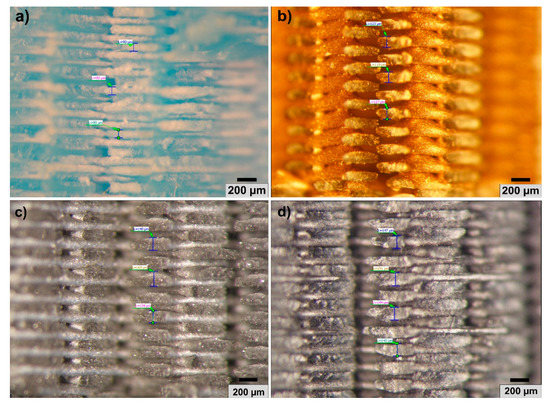
Figure 9.
Macrostructural aspects at stereomicroscope of experimental samples in transversal cross section, with 100% interior fill percentage and 60° thread deposition (a) polylactic acid material; (b) polylactic acid material with copper particles; (c) polylactic acid material with aluminum particles; (d) polylactic acid material with graphene particles.
The stereomacrostructural analysis in longitudinal section of the fiber fracture is shown in the images in Figure 4, Figure 5, Figure 6 and Figure 7.
The simple PLA in Figure 4a,c,e shows the propagation in zig-zag, at an angle of 45°, with the crack taking place in the calibrated zone. At an angle of 60% of deposition, the propagation of the front is zig-zag, on the direction perpendicular to the direction of task application.
In the case of PLA with Cu insertion, similar aspects of the crack propagation are noticed: at 45° deposit angle, the fracture is at 45° in zigzag (Figure 5a,c,e), and at 60° angle of deposition, the crack is zig-zag perpendicular to the direction of load propagation (Figure 5b,d,f).
In PLA with Al insert, generally the crack takes place when passing from the calibrated part to the uncalibrated part (Figure 6). Moreover, at 45° filling angle, the front propagates at 45° (Figure 6a,c,e), while at an angle of 60°, the fracture is zig-zag (Figure 6b,d,e) on directives perpendicular to the direction of the load.
In the case of PLA + graphene, the breaking edge also appears at the transition between the calibrated and the uncalibrated part (Figure 7). In the case of 45° filling angle (Figure 7a,c,e) at all filling degrees, the fracture is in zig-zag, while at 60° filling angle (Figure 7b,d,f), the rupture is perpendicular to the breaking direction.
As can be seen, in the longitudinal section, the propagation front of the crack is dependent on the filling angle. At an angle of 45°, the crack is at 45°, while at an angle of 60°, the fracture is zig-zag perpendicular to the direction of load propagation.
The stereomicrostructural analysis in cross section allows both the evaluation of the rupture character and the highlighting of the correlation of the deformed fibers size and the degree of filling.
At 60° of filling, in the smallest angle of deposition that has been noticed, namely 45°, the fibers are undeformed, have sharp ends, and are partially folded. The presence of Cu, Al, and graphene inserts determines a rounded appearance of the fiber ends with the same spacing (Figure 8b,c,d).
At an intermediate degree of filling of 80%, there is also a partial character of folding and partially deformed fibers, regardless of the chemical composition of the fibers.
If the folding is 100% (Figure 9), there is a strongly deformed aspect of the fibers: the presence of Al and graphene can even lead to the welding of the fibers (Figure 9c,d) without any gap.
All the fibers are intertwined. In addition, the increase of the filling angle determines the decrease of the fiber height.
We may conclude that the analysis in longitudinal section of the specimens, i.e., in the parallel direction of application of the load, showed that the very low ductility of the specimens, with elongations located in the range 2%–5%, determined a propagation front of fracture in a general zig-zag shape, specific to brittle fracture. At the same time, in all specimens, regardless of their chemical composition, it was observed that the angle of inclination of the deposited fibers influences the propagation mode: thus at a deposition angle of 45°, the fracture is arranged at an angle of 90°, with a transverse sectioning of the fibers, without elongation, in zig-zag (a, c, and e); at an angle of 60°, the propagation front is in zig-zag, approximately in a direction perpendicular to the direction of application of the breaking load (b, d, and f). Another interesting observation was that the fibers generally break, with small exceptions, in the area of variation of the specimen size, which indicates that the elongation is minimal and the rupture does not occur in the calibrated area of the specimen, meaning that the fracture is predominantly brittle.
The transversal cross-sectional analysis of the fractured specimens highlighted (Figure 4, Figure 5, Figure 6, Figure 7 and Figure 8) the fragile/cleavage character of the fracture—all the fibers having a fracture front that crosses the surface almost linearly. Thus, in the simple specimens made from PLA, it can be observed that the fibers have certain spacing at the filling degree of 60% and 80%, regardless of the deposition angle, while at a degree of 100% filling, the spacing disappears, with the ends of the fibers being intertwined.
A simple observation between the images from Figure 8 and Figure 9 show the manner of deformation of the fibers. So, if the fiber has low deformation (around ΔL = 4 mm) aspect in 60% interior fill percentage and 45° thread deposition (for all types of PLA with or without particle insertion), increasing the printing parameters at 100% interior fill percentage and 60° thread deposition goes to increasing the deformation of the fibers, by decreasing at around ΔL = 2 mm.
So, by measuring the heights of the fibers and presenting the data in transversal cross section, we propose a new method in the quantitative fracture analysis correlating the fiber height and the filling parameters (deposition angle and filling percentage).
Results regarding fourier transform infrared (FTIR) analysis are given in Figure 10.
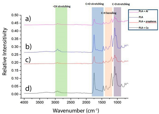
Figure 10.
Fourier transform infrared (FTIR) spectra of experimental samples: a—polylactic acid material with aluminum particles (PLA + Al); b—polylactic acid material (PLA); c—polylactic acid material with graphene particles (PLA + graphene); d—polylactic acid material with copper particles (PLA + Cu).
Figure 10 shows FTIR spectra of experimental samples PLA, PLA + Cu, PLA + Al, and PLA + graphene composites, respectively. PLA shows characteristic stretching frequencies for C=O, –CH3 asymmetric, –CH3 symmetric, and C–O, at 1746, 2995, 2946, and 1080 cm−1, respectively. Bending frequencies for –CH3 asymmetric and –CH3 symmetric have been identified at 1452 and 1361 cm−1, respectively. One may remark the following observations:
- All the samples show almost same absorption peaks as simple PLA, no matter the type of insertion (Cu, Al or graphene),
- PLA + Al and PL + Cu have the same amplitude at 1080 cm−1, meanwhile PLA and PLA + graphene have a lower amplitude at the same frequency (1080 cm−1).
Results regarding SEM analysis are given in Figure 11.
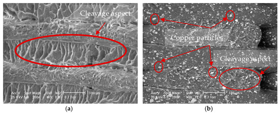
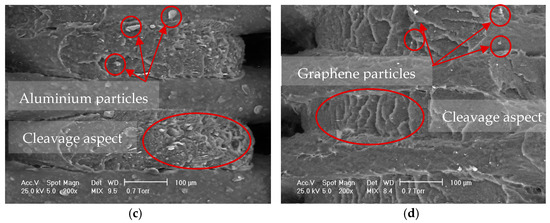
Figure 11.
SEM images of the experimental samples, in transversal cross section, with 100% interior fill percentage and 60° thread deposition 3D printing parameters: (a) polylactic acid material (PLA); (b) polylactic acid material with copper particles (PLA + Cu); (c) polylactic acid material with aluminum particles (PLA + Al); (d) polylactic acid material with graphene particles (PLA + graphene).
Figure 11 show the SEM images of the experimental samples, in transversal cross section, with 100% interior fill percentage and 60° thread deposition 3D printing parameters. In all samples, the fracture has the same structural feature, e.g., cleavage aspect, with wave propagation. In addition, one may remark the size of the particles: in PLA + Cu, there are particles around 15–20 µm; in PLA + Al, there are particles around 18–21 µm; in PLA + graphene, there are particles around 2–7 µm.
4. Discussion
The data obtained in this paper are innovative in the sense of obtaining information on the structural behavior highlighted by stereomicroscopy. We cannot compare the stereomicroscopic images because there are no other reported data. Our data give useful information about fiber dimensions versus printing parameters (interior angle depositions and filling percentage). Some information can be compared with the SEM analysis, as presented in the paper [38] and also with color PLA samples having the same brittle fracture in [39].
On the other hand, some observations could be made by comparing our work with other research by mechanical properties of other thermosetting fiber using additive manufacturing technology. So, Ning [40] studied additive manufacturing of carbon-fiber-reinforced thermoplastic. Their research involved comparison with 3D printed thermosets pieces with or without carbon (in different proportion), making observations concerning tensile properties (including tensile strength, Young’s modulus, toughness, yield strength, and ductility) and flexural properties (including flexural stress, flexural modulus, flexural toughness, and flexural yield strength) of specimens. Our research is conducted firstly on other types of materials (PLA with or without particle insertion) and secondly on making quantitative measures on fiber heights after 3D printing pieces (with different printing parameters). Goh [41] studied the mechanical behavior of carbon-fiber-reinforced thermoplastic in comparison with other continuous fibers. Their study was made on reinforced fibers comparing the fiber breakage with matrix fiber, whereas our study involved fibers with different particle insertion, making the correlation between fiber heights and printing parameters. We can make any comparisons with other researches of Naranjo-Lozada [42] in which was studied 3D printed components with continuous-fiber-reinforced and chopped carbon fiber. They used other methods of printing architectures, with same volume fracture (naming them rectangular / triangular 10% and rectangular / triangular 70%). Our work used other printing parameters, naming them: filling percentages (60%, 80%, and 100%) and interior angular deposition (45% and 60%). So, one may remark the diversity of discussion for the fracture behavior of continuous-fiber-reinforced and chopped carbon fiber or PLA with or without particle insertion. That is why our observations may be different from other researches.
5. Conclusions
Three-dimensional printing in different conditions, namely 60%, 80%, and 100% filling percentage and 45° and 60° angle degrees of the polylactic acids (PLA) materials with and without different particle insertions (respectively copper, aluminum, or graphene) lead to different mechanical and fracture behavior. The paper presents for the first time a measurement of fiber: height in transversal cross section as a new method for quantitative fracture analysis; and secondly, a correlation between fiber dimensions and the printing parameters (deposition angle and filling parameters). The following conclusion is taken into considerations:
- Regarding the FTIR analysis, all the samples show almost same absorption peaks as simple PLA, no matter the type of insertion (Cu, Al or graphene), PLA + Al and PL + Cu have the same amplitude at 1080 cm−1, meanwhile PLA and PLA + graphene have a lower amplitude at the same frequency (1080 cm−1).
- Regardless the chemical composition of the specimens, the same type of evolution of the values of mechanical strengths can be noticed: they increase slightly with the increase of the filling angle (from 45° to 60°) and decrease with the increase of the filling degree (from 60% to 80% and 100%).
- A hierarchy, in descending order of the elongation values can be observed: simple PLA (4.2%–4.6%) followed by PLA with aluminum particle inserts (3.2–4.1), followed by PLA with particle graphene inserts (2.6%–4%), the lowest values being recorded for PLA specimens with particle copper inserts, 1.8%–2.7%.
- Regarding the fiber heights measured after fracture of the 3D printing materials, the evolution of the fiber heights of all the samples, irrespective of the chemical composition of the samples, is the same: increasing the angle degree or filling percentage lead to a decrease of the fiber height. It means that the ductility potential of the fiber can increase due to these printing parameters; the values of fiber height with different insertions are higher than the simple PLA, in all conditions. A hierarchy may be made: the highest values of the fiber heights are for PLA + particle aluminum, followed by PLA + particle graphene and PLA + particle copper.
- Generally, the samples may be broken in the transition zone with zig-zag fracture, having a brittle/cleavage aspect, irrespective of the chemical composition of the sample.
- The fibers generally break, with small exceptions, in the area of variation of the specimen size, which indicates that the elongation is minimal and the rupture does not occur in the calibrated area of the specimen, meaning that the fracture is predominantly brittle.
- Regarding the SEM analysis, all samples the fracture has the same structural feature, i.e., cleavage aspect, with wave propagation. In addition, one may remark the size of the particles: in PLA + Cu, there are particles around 15–20 µm; in PLA + Al, there are particles around 18–21 µm; in PLA + graphene, there are particles around 2–7 µm.
Author Contributions
Conceptualization: B.G. and N.E.P.; methodology: B.G. and G.J.; validation: B.G., I.V.A. and C.M. (Corneliu Munteanu); formal analysis: G.P. and C.G.; investigation: C.M. (Claudia Milea); resources: B.G., N.E.P., I.V.A., G.J., C.M. (Claudia Milea), G.P., C.G., C.M. (Corneliu Munteanu). and B.I.; writing—original draft preparation: B.G.; writing—review and editing: B.G. and N.E.P.; funding acquisition: B.G., N.E.P., I.V.A., G.J., C.M. (Claudia Milea), G.P., C.G. and C.M. (Corneliu Munteanu). All authors have read and agreed to the published version of the manuscript.
Funding
This research received no external funding.
Institutional Review Board Statement
Not applicable.
Informed Consent Statement
Not applicable.
Data Availability Statement
Nicoleta Elisabeta Pascu and Gabriel Jiga conducted research involving the determination of the mechanical characteristics of these samples, which were published in https://revmaterialeplastice.ro, 2019 Volume 56, Issue 4, pp. 783–800 (accessed on 30 December 2019).
Conflicts of Interest
The authors declare no conflict of interest.
References
- Messimer, L.S. Characterization and processing behavior of heated aluminum-polycarbonate composite build plates for the fdm additive manufacturing process. J. Manuf. Mater. Process. 2018, 8, 12. [Google Scholar] [CrossRef]
- Ranjbar, M.; Pardakhty, A.; Tahmipour, B.; Mohamadzadeh, I. Novel CaO/polylactic acid nanoscaffold as dental resin nanocomposites and the investigation of physicochemical properties. Luminescence 2019, 34, 360–367. [Google Scholar] [CrossRef] [PubMed]
- Narayanan, N.; Roychoudhury, P.K.; Srivastava, A. L (+) lactic acid fermentation and its product polymerization. Electron. J. Biotechnol. 2004, 7, 167. [Google Scholar]
- Drumricht, R.E.; Gruber, P.R.; Henton, D.E. Polylactic acid technology. Adv. Mater. 2000, 12, 1841–1846. [Google Scholar] [CrossRef]
- Auras, R.; Harte, B.; Selke, S. An overview of polylactides as packaging materials. Macromol. Biosci. 2004, 4, 835. [Google Scholar] [CrossRef]
- Martin, O.; Avérous, L. Poly (lactic acid): Plasticization and properties of biodegradable multiphase systems. Polymer 2001, 42, 6209–6219. [Google Scholar] [CrossRef]
- Lasprilla, A.J.; Martinez, G.A.; Lunelli, B.H.; Jardini, A.L.; Filho, R.M. Poly-lactic acid synthesis for application in biomedical devices—A review. Biotechnol. Adv. 2012, 30, 321–328. [Google Scholar] [CrossRef] [PubMed]
- Malmgren, T.; Mays, J.; Pyda, M. Characterization of polylactic acid by size exclusion chromatography, differential refractometry, light scattering and thermal analysis. Therm. Anal. Calorim. 2006, 83, 35–40. [Google Scholar] [CrossRef]
- Valerga, A.P.; Batista, M.; Salguero, J.; Girot, F. Influence of PLA filament condition on characteristics of FDM parts. Materials 2018, 11, 1322. [Google Scholar] [CrossRef] [PubMed]
- Creality. Available online: https://www.creality3dshop.eu/collections/cr-series-3d-printer/products/creality-cr-10s-diy-desktop-3d-printer-300x300x400mm (accessed on 20 March 2021).
- All3DP. Available online: https://all3dp.com/2/how-3d-printer-filament-made/ (accessed on 20 March 2021).
- Cavalu, S.; Simon, V. Proteins adsorption to orthopedic biomaterials-vibrational spectroscopic evidence. J. Optoelectron. Adv. Mater. 2007, 9, 3297–3302. [Google Scholar]
- Jamshidian, M.; Tehrany, E.A.; Imran, M.; Jacquot, M.; Desobry, S. Poly-lactic acid: Production, applications, nanocomposites, and release studies. Comprehens. Rev. Food Sci. Food Saf. 2010, 9, 552–571. [Google Scholar] [CrossRef] [PubMed]
- Farah, S.; Anderson, D.G.; Langer, R. Physical and mechanical properties of PLA, and their functions in widespread applications—A comprehensive review. Adv. Drug Deliv. Rev. 2016, 107, 367–392. [Google Scholar] [CrossRef]
- Chacón, J.M.; Caminero, M.A.; García-Plaza, E.; Núñez, P.J. Additive manufacturing of PLA structures using fused deposition modelling: Effect of process parameters on mechanical properties and their optimal selection. Mater. Des. 2017, 124, 143–157. [Google Scholar] [CrossRef]
- Ezeh, O.H.; Susmel, L. Designing additively manufacture notched PLA against static loading. In Proceedings of the International Symposium on Notch Fracture, Santander, Spain, 20 March 2017. [Google Scholar]
- Jadallah, O.; Bagni, C.; Askes, H.; Susmel, L. Microstructural length scale parameters to model the high-cycle fatigue behaviour of notched plain concrete. Int. J. Fatigue 2016, 82, 708–720. [Google Scholar] [CrossRef]
- Jerez-Mesa, R.; Travieso-Rodriguez, J.A.; Llumà-Fuentes, J.; Gomez-Gras, G.; Puig, D. Fatigue lifespan study of PLA parts obtained by additive manufacturing. Procedia Manuf. 2017, 13, 872–879. [Google Scholar] [CrossRef]
- Lanzotti, A.; Grasso, M.; Staiano, G.; Martorelli, M. The impact of process parameters on mechanical properties of parts fabricated in PLA with an open-source 3-D printer. Rapid Prototyp. J. 2015, 21, 604–617. [Google Scholar] [CrossRef]
- Ezeh, O.H.; Susmel, L. On the fatigue strength of 3D-printed polylactide (PLA). Procedia Struct. Integr. 2018, 9, 29–36. [Google Scholar] [CrossRef]
- DeStefano, V.; Khan, S.; Tabada, A. Applications of PLA in modern medicine. Eng. Regen. 2020, 1, 76–87. [Google Scholar]
- Ranjbar, M.; DehghanNoudeh, G.; Hashemipour, M.A.; Mohamadzadeh, I. A systematic study and effect of PLA/Al2O3 nanoscaffolds as dental resins: Mechanochemical properties. Artif. Cells Nanomed. Biotechnol. 2019, 47, 201–209. [Google Scholar] [CrossRef] [PubMed]
- Haifeng, X.; Xiaozu, W.; Yu, W.; Feimin, Z.; Chen, C.; Yang, X. Effects of sol-gel processed silica coating on bond strength of resin cements to glass-infiltrated alumina ceramic. J. Adhes. Dent. 2009, 11, 49–55. [Google Scholar]
- Weiguo, W.; Xiang, S.; Li, H.; Yu, G.; Jinghao, B.; Lijuan, S.; Jihua, C. Structure-property relationships in hybrid dental nanocomposite resins containing monofunctional and multifunctional polyhedral oligomericsilsesquioxanes. Int. J. Nanomed. 2014, 10, 841–852. [Google Scholar]
- Mirjalil, F.; Chuah, L.; Salahi, E. Mechanical and morphological properties of polypropylene/nano α-Al2O3 composites. Sci. World J. 2014, 2014, 718765. [Google Scholar]
- Cavalu, S.; Banica, F.; Simon, V. Surface modification of alumina/zirconia ceramics upon different fluoride-based treatments. Int. J. Appl. Ceram. Technol. 2014, 11, 402–411. [Google Scholar] [CrossRef]
- Speroff, L.; Darney, P.D. Intrauterine contraception. In A Clinical Guide for Contraception, 5th ed.; Lippincott Williams Wilkins: Philadelphia, PA, USA, 2011; pp. 239–280. ISBN 978-1-60831-610-6. [Google Scholar]
- World Health Organization. World Health Organization Model List of Essential Medicines: 21st LIST 2019; World Health Organization: Geneva, Switzerland, 2019. [Google Scholar]
- Berger-Kulemann, V.; Einspieler, H.; Hachemian, N.; Prayer, D.; Trattnig, S.; Weber, M.; Ba-Ssalamah, A. Magnetic field interactions of copper-containing intrauterine devices in 3.0-tesla magnetic resonance imaging: In vivo study. Korean J. Radiol. 2013, 14, 416–422. [Google Scholar] [CrossRef] [PubMed][Green Version]
- Hashim, N.; Yusoh, K. Graphene modifications in polylactic acid nanocomposites: A review. Polym. Bull. 2015, 72, 931–961. [Google Scholar]
- Reza, A.; Azman, H.; Norhayani, O.; Zurina, M. Characterizations of Carbon-Based Polypropylene. In Carbon-Based Polymer Nanocomposites for Environmental and Energy Applications; Elsevier Science: Johor Bahru, Malaysia, 2018. [Google Scholar] [CrossRef]
- Sumit, G.; Vinayak, S.; Shilpa, S. Graphene-based nanomaterials for drug delivery and tissue engineering. J. Control. Release 2013, 173, 75–88. [Google Scholar]
- Hu, S.; Zeng, Y.; Yang, S.; Qin, H.; Cai, H.; Wang, J. Application of Graphene Based Nanotechnology in Stem Cells Research. J. Nanosci. and Nanotech. 2015, 15, 6327–6341. [Google Scholar] [CrossRef]
- Edelmann, J.; Albrecht, M.; Gehde, M.; Adamy, M.; Hopmann, C.; Deferme, W.; Lecomte, J. Graphen—Möglichkeiten und Grenzen in polymeren Kompositen. In Proceedings of the Technomer 2017: Fachtagungüber Verarbeitung und Anwendung von Polymeren, Chemnitz, Germany, 25–27 October 2017; p. 25. [Google Scholar]
- Dobrescu, T.; Pascu, N.E.; Jiga, G.; Simion, I.; Adir, V.; Enciu, G.; Tudose, D.D. Tensile behavior of PLA and PLA composite materials under different printing parameters. Mater. Plast. 2019, 56, 783–800. [Google Scholar] [CrossRef]
- Instron 8800. Available online: https://www.instron.us/en-us/products/testing-systems/dynamic-and-fatigue-systems/8800-high-strain-rate (accessed on 20 March 2021).
- Olympus. Available online: https://www.olympus-lifescience.com/en/microscopes/stereo/szx7/ (accessed on 20 March 2021).
- Nagendra, K.M.; Vikas, R.; Pushpendra, S. An overview of mechanical properties and form error for rapid prototyping. CIRP J. Manuf. Sci. Technol. 2020, 29, 53–70. [Google Scholar]
- Wittbrodt, B.; Pearce, J.M. The effects of PLA color on material properties of 3-D printedcomponents. Addit. Manuf. 2015, 8, 110–111. [Google Scholar]
- Ning, F.; Cong, W.; Qiu, J.; Wei, J.; Wang, S. Additive manufacturing of carbon fiber reinforced thermoplastic composites using fused deposition modeling. Compos. Part B Eng. 2015, 80, 369–378. [Google Scholar] [CrossRef]
- Goh, G.D.; Toh, W.; Yap, Y.L.; Ng, T.Y.; Yeong, W.Y. Additively manufactured continuous carbon fiber reinforced thermoplastic for topology optimized unmanned aerial vehicle structures. Compos. Part B Eng. 2021, 216, 108840. [Google Scholar] [CrossRef]
- Naranjo-Lozada, J.; Ahuett-Garza, H.; Orta-Castañón, P.; Verbeeten, W.M.; Sáiz-González, D. Tensile properties and failure behavior of chopped and continuous carbon fiber composites produced by additive manufacturing. Addit. Manuf. 2019, 26, 227–241. [Google Scholar] [CrossRef]


Publisher’s Note: MDPI stays neutral with regard to jurisdictional claims in published maps and institutional affiliations. |
© 2021 by the authors. Licensee MDPI, Basel, Switzerland. This article is an open access article distributed under the terms and conditions of the Creative Commons Attribution (CC BY) license (https://creativecommons.org/licenses/by/4.0/).