Article

Tribological Properties of a Mesh-Like Nanostructured Diamond-Like Carbon (DLC) Lubricated with a Fully Formulated Oil at DLC/Steel Contacts under Boundary Lubrication

1
Mechanical Engineering, Kyoto Institute of Technology, Goshokaidou-chou Matsugasaki Sakyo-ku Kyoto, Kyoto 606-8585, Japan
2
Department of Mechanical Engineering, Tokyo University of Science, 6-3-1 Niijuku, Katsushika-ku, Tokyo 125-8585, Japan
3
Tokyo Metropolitan Industrial Technology Research Institute, 2-4-10, Aomi, Koto-ku, Tokyo 135-0064, Japan
4
Nippon ITF Corporation, 575, Kuzetonoshirocho, Kyoto Minami-ku, Kyoto 601-8205, Japan
*
Authors to whom correspondence should be addressed.
Coatings 2021, 11(7), 746; https://doi.org/10.3390/coatings11070746
Submission received: 30 May 2021 / Revised: 17 June 2021 / Accepted: 18 June 2021 / Published: 22 June 2021
(This article belongs to the Special Issue Tribology and Mechanical Behavior of Amorphous Carbon Coatings)

Abstract

:
The present paper describes the tribological properties of a mesh-like nanostructure of diamond-like carbon (DLC) in a formulated engine oil at DLC/steel contacts. This novel nanostructured DLC was characterized as a non-hydrogenated amorphous carbon (a-C) with a nano-mesh structure layer at the outermost surface, herein named NM-a-C. From the results of our friction tests, we observed that the NM-a-C/steel tribopair exhibited lower friction and higher wear-resistance than the a-C:H/steel tribopair, though the mechanical properties were nearly identical. The analytical result indicated that the tribofilm formation process and the chemical composition of the tribofilm varied depending on the types of the DLC. In particular, thicker MoS2-rich tribofilms formed on the NM-a-C surface. Hence, the NM-a-C structure promoted the formation of MoS2 under the lubrication with the fully formulated oil, leading to lower friction and high wear-resistance at the DLC/steel contact under boundary lubrication conditions.

1. Introduction

Diamond-like carbon coating (DLC) is one of the hardest tribological coatings and has been used in various tribological applications. Presently, DLCs are typically used on the sliding components of automotive engines, such as the tappet, camshaft, piston rings, and pistons due to their excellent tribological performance [1]. For the automotive sliding components, the combination of DLCs and lubricants plays important role in the tribological behavior of the sliding system. Especially, under boundary-mixed lubrication regime conditions, DLC surfaces react with the lubricant additives, such as anti-friction and wear additives in engine oils at sliding contact surfaces. The tribochemical reaction between DLC surfaces and lubricant additives dominates the tribological performance of the DLC-sliding system due to the formation of molecular adsorbent or chemical reaction films, which are often referred to as “tribofilms” [2,3,4,5,6,7]. Typically, the characteristics of a tribofilm strongly depend on the chemical and mechanical properties of the sliding materials. For a DLC-sliding system, the common aspects that affect the characteristics of the tribofilm are the sp2/sp3 ratio, hydrogen concentration, and other metallic doping agents; these factors also affect the tribological performance [6,7,8]. Vengudusamy et al. reported the tribological performance of non-doped and element-doped DLC films lubricated with a base oil with and without lubricant additives, such as zinc dialkyldithiophosphates (ZDDP) and molybdenum dialkyldithiocarbamate (MoDTC) [6,7]. These previous reports suggest that both tribofilm morphology and tribofilm formation rate depend on the DLC type [6,7]. Therefore, the appropriate and informed design of DLCs is an effective approach to improve the tribological performance of DLCs under boundary lubrication.
Industrial DLCs are commonly classified as one of four types: amorphous carbon (a-C), tetrahedral amorphous carbon (ta-C), hydrogenated amorphous carbon (a-C:H), and hydrogenated tetrahedral amorphous carbon (ta-C:H); placement within one of these categories is based on the sp2/sp3 ratio and hydrogen concentration [9]. Among DLC films, a-C films exhibit interesting tribological performance due to their structure, mainly composed of sp2 carbon [8,9]. In previous studies [8,9], a-C films exhibited lower friction than other DLC types during an initial performance period under boundary lubrication conditions; this performance is due to a-C films possessing a rich graphite-like structure. However, the a-C film also had low durability and was easily worn during sliding motions, due to its low mechanical properties and low adhesive strength between the steel substrate and the film [8,9]. Based on these findings, enhanced a-C films with higher durability than present conventional films would excel at tribological applications.
Typically, a novel nano-mesh-like structure with an a-C (NM-a-C) film features a mesh-structured layer at the outermost surface. This mesh structure is developed by an arc ion plating (AIP) method [10]. Herein, we investigate the potential of an NM-a-C film for tribological applications when operated under boundary lubrication conditions. To compare the tribological properties of the NM-a-C and conventional DLC films under boundary lubrication conditions, we conducted a friction test at an a-C:H/steel and NM-a-C/steel interface lubricated with a fully formulated oil containing MoDTC and ZDDP using a friction tester equipped with a Raman spectroscopy and space layer imaging method (SLIM) [11,12] to evaluate friction, wear performance, and tribofilm formation processes.

2. Materials and Methods

2.1. Characterization of Materials

Both an AISI 52100 steel disk coated with NM-a-C and a-C:H DLC and a steel ball were employed as test specimens. The specimen sizes of the disk and ball are φ 24 mm × t 7.9 mm and φ 19 mm. The fully formulated oil lubricant used in this study was categorized as 0W-20, which contains MoDTC and ZDDPs as anti-friction and wear additives, respectively.
All DLC samples were provided by the Nippon ITF Inc. The NM-a-C and a-C:H DLC were deposited on the steel disk by physical vapor deposition (PVD) and chemical vapor deposition (CVD) methods, respectively. The cross-section was prepared using a focused ion beam (FIB) and was observed by transmission electron microscopy (TEM, H9000 UHR, JP) [10]. The nano-indentation hardness of the DLCs was obtained using a nano-indenter (Ti950, Hysitron, Minneapolis, MN, USA). The hydrogen concentration of the DLCs was evaluated via elastic recoil detection analysis (ERDA). The surface roughness of the DLC disks was measured by laser optical microscopy (OLS5000, Olympus, Tokyo, Japan) and atomic force microscopy (AFM) (Nano navi Real, SII, Tokyo, Japan) using a commercial cantilever (SI-DF20, Olympus, Japan) made of silicon with an integrated pyramidal tip (tip radius: approximately 10 nm). The sp2/sp3 ratio was evaluated using X-ray photoelectron spectroscopy (XPS) (VG Scientific Theta Probe, Thermo Fisher Scientific, Waltham, MA, USA).

2.2. Friction Test and Raman-SLIM Analyses

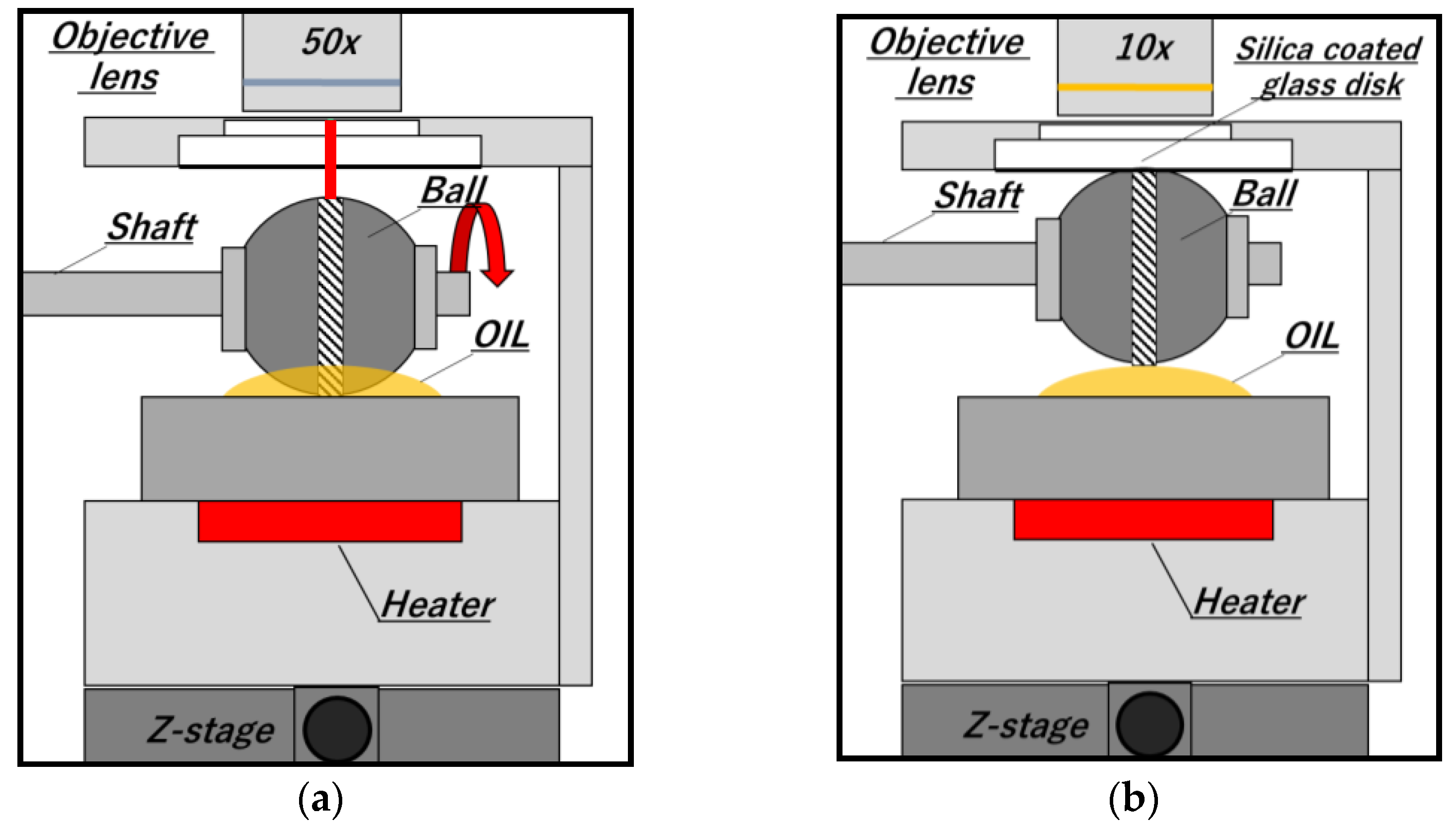
A laboratory constructed ball-on-disk tribometer equipped with Raman and SLIM was used for the friction test. A simplified diagram of the tester is shown in Figure 1. The test was conducted under the following test conditions: applied load: 50 N; rotational speed: 0.04 m/s; temperature: 100 °C; amount of the engine oil: 5 µL; a test duration: 1 h and tribopairs: DLC disk/steel ball tribopairs.
The Raman analysis was conducted on the ball surfaces to evaluate the formation process of the tribofilms (inVia confocal Raman, Renishaw, Wotton-under-Edge, UK, 785 nm laser) The radius of the laser spots and maximum power output were φ 6 μm and 5 mW. The Raman analytical point was the worn surface of the rotating DLC-coated ball as shown in Figure 2a.
A schematic diagram of the SLIM analysis is provided in Figure 2b. A silica-coated glass disk and an optical microscope with the Raman analyzer were used to obtain SLIM images. In the analysis, an optical microscope with a Raman analyzer and an objective lens with 10× magnification was used to obtain images of the interference fringes of the contacts between a silica-coated glass disk and the steel ball. The images were analyzed by using MATLAB (MathWorks, Commonwealth of Massachusetts, USA) to obtain the RGB intensities in the images, which were then used to calculate Hue values. The Hue values were converted into the film thickness using a calibration value that was mathematically obtained using the relationship between the Hue values and the gap between the ball and the flat disk [5].

2.3. Chemical Analysis for Tribofilms

Time-of-Flight Secondary Ion Mass Spectrometry (TOF-SIMS, ULVAC TRIFT III, UlVAC, Kanagawa, Japan, primary ion: Ga+, impact energy: 15 kV, exposure time: 180 s) examinations were conducted on the worn surfaces of the DLC disks washed by n-hexanes.

3. Results

3.1. Characterization of the DLC films

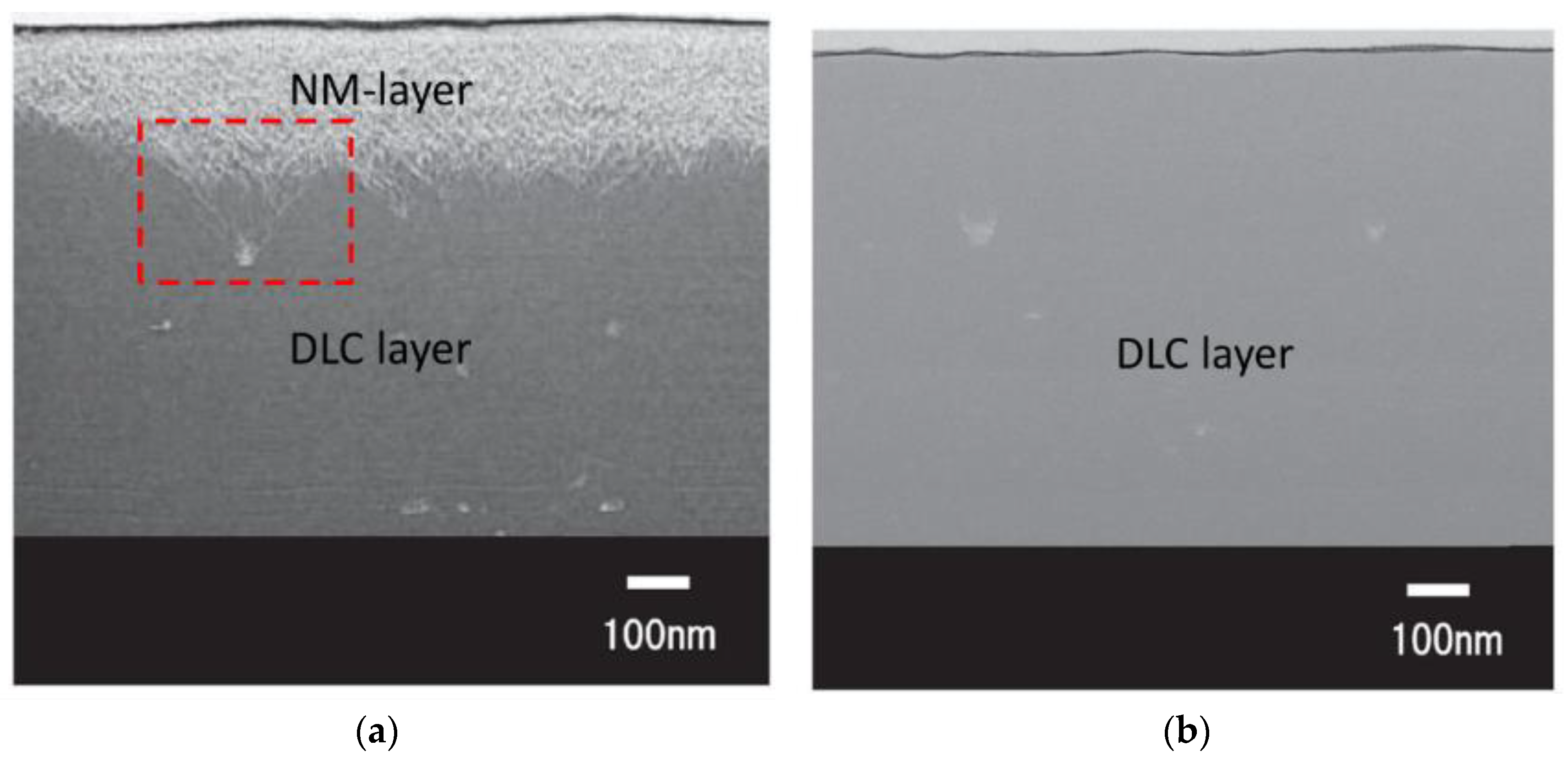
Figure 3 shows the deposition temperature behavior of both the NM-a-C and the conventional DLC film. It is worth noting in Figure 3 that the deposition temperature of the NM-a-C film gradually increased during the deposition process. Figure 4 shows the TEM image of the Focused Ion Beam (FIB) prepared cross-sectional of the NM-a-C film and the conventional DLC film [10]. As shown in Figure 4a, the nano-mesh-like structured layer (approximately: 240 nm) and the DLC layer were observed. Moreover, the nano-mesh-like structured layer seems to have grown and originated from deposited carbon particles, denoted by the red dotted lines in Figure 4a. On the contrary, as is shown in Figure 4b, the DLC layer was only observed by the conventional deposition method, see Figure 4b.
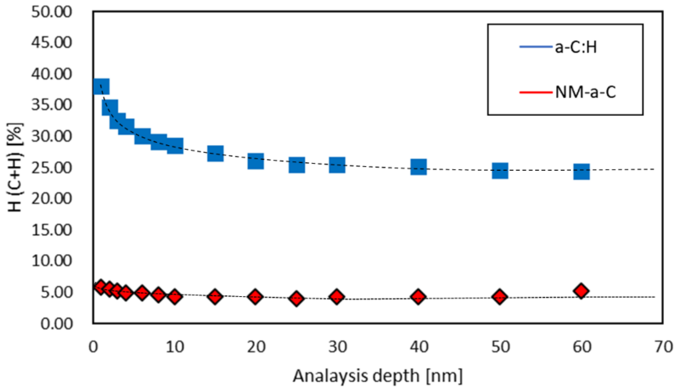
Figure 5 shows the ERDA hydrogen concentration analysis results for the as-deposited DLC films as a function of the analytical depth. As shown in Figure 5, the hydrogen concentration of both a-C:H and NM-a-C films at the near-surface region (from an analytical depth of 0–10 nm) gradually decreased as the analytical depth increased. This behavior was due to the existence of contaminants within the near-surface region. In the DLC bulk region (analytical depth of 10–60 nm), the hydrogen concentration of both the NM-a-C and the a-C:H films were stable at values of 4.5 at % and 28 at %, respectively.
Figure 6 and Table 1 show the typical XPS C1s spectra of the films and the XPS C1s analytical results, respectively. The sp3/(sp2 + sp3) ratio of the DLC films was calculated via the XPS peak height ratio of the C = C sp2 peak (284.5 eV) and the C-C, C-C-H sp3 (285.3 eV) peaks, as shown in Figure 6 [13]. Notably, from Table 1, the sp3/(sp2 + sp3) ratio of both NM-a-C and a-C:H films was 48.5% and 50%, respectively. There was a little difference between the sp3/(sp2 + sp3) ratios of the DLCs. The difference between the sp3/(sp2 + sp3) ratios of each NM-a-C and a-C:H films could be explained by the ratio of C-H bonding in the film. A higher C-H bond ratio relates to a higher sp3/(sp2 + sp3) ratio for the DLC films. Hence, the sp3/(sp2 + sp3) ratio of the a-C:H film is typically higher than that of the NM-a-C film.
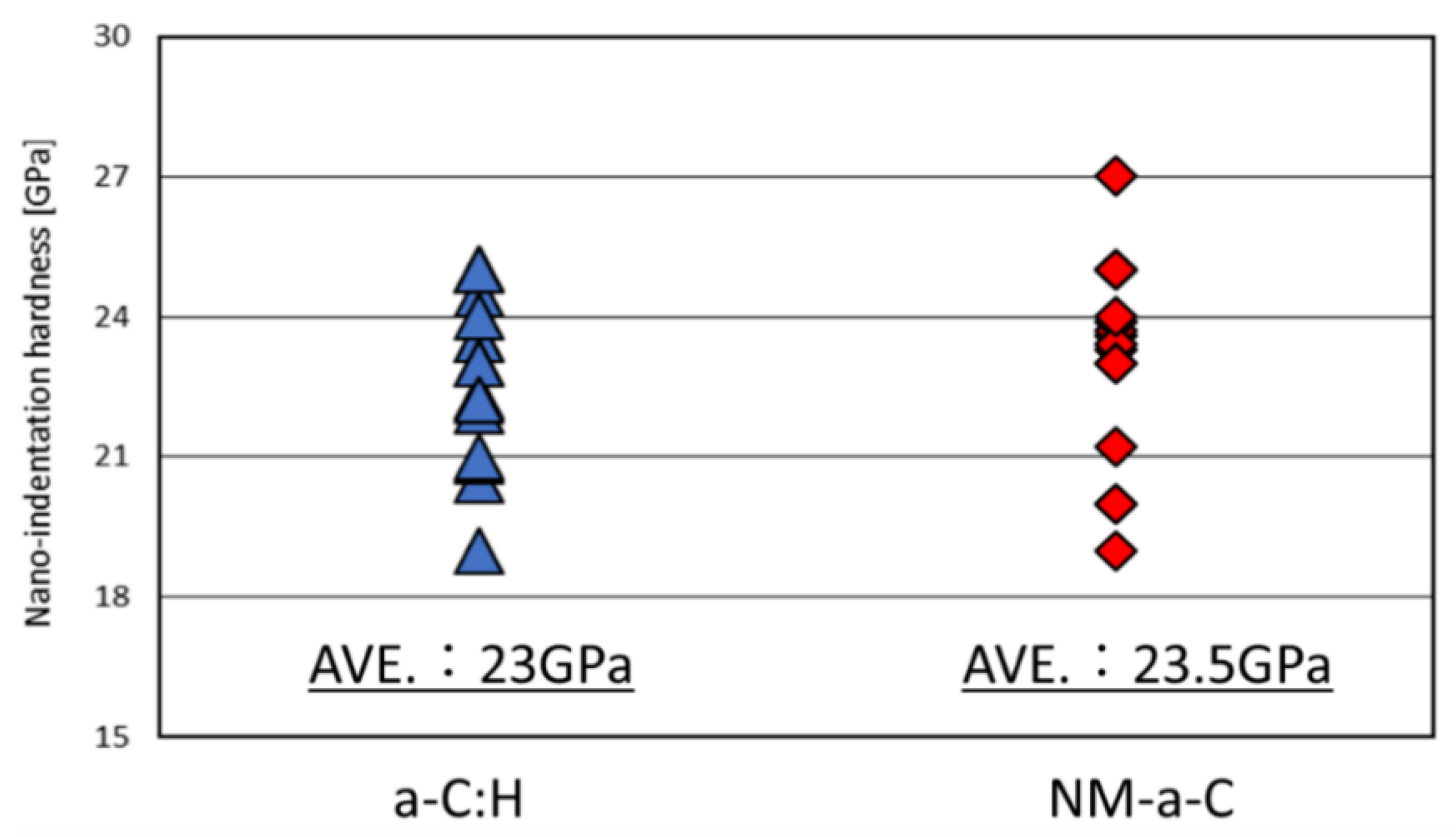
Figure 7 shows the nano-indentation results of the as-deposited DLC films. In Figure 7, the average nano-indentation hardness of both the NM-a-C film and the a-C:H film was 23.5 and 23 GPa, respectively; these hardness findings reveal the similarity in the nanoindentation hardness between both DLCs, though the film structures were different. Figure 8 shows the laser optical microscopic images and AFM topographical images (5 × 5 μm2 scan size) and the surface roughness parameter, Sa, of the as-deposited DLC films. In Figure 8a,b, several carbon deposits on the a-C film were observed whereas they were not observed on the a-C:H surface. Notable from Figure 8c,d, the NM-a-C has nodular structure regions and liner polishing marks. On the contrary, the a-C:H film has a uniform topographical feature. The topographical difference between the NM-a-C and a-C:H films may be caused by differences in the deposition techniques (PVD and CVD) used to fabricate the films. Moreover, the surface roughness of both DLCs was nearly identical. Hence, the difference in the hardness and the roughness between the DLC films are not the dominant contributions to any findings obtained during our tribological experiments.

3.2. Friction and Wear Results

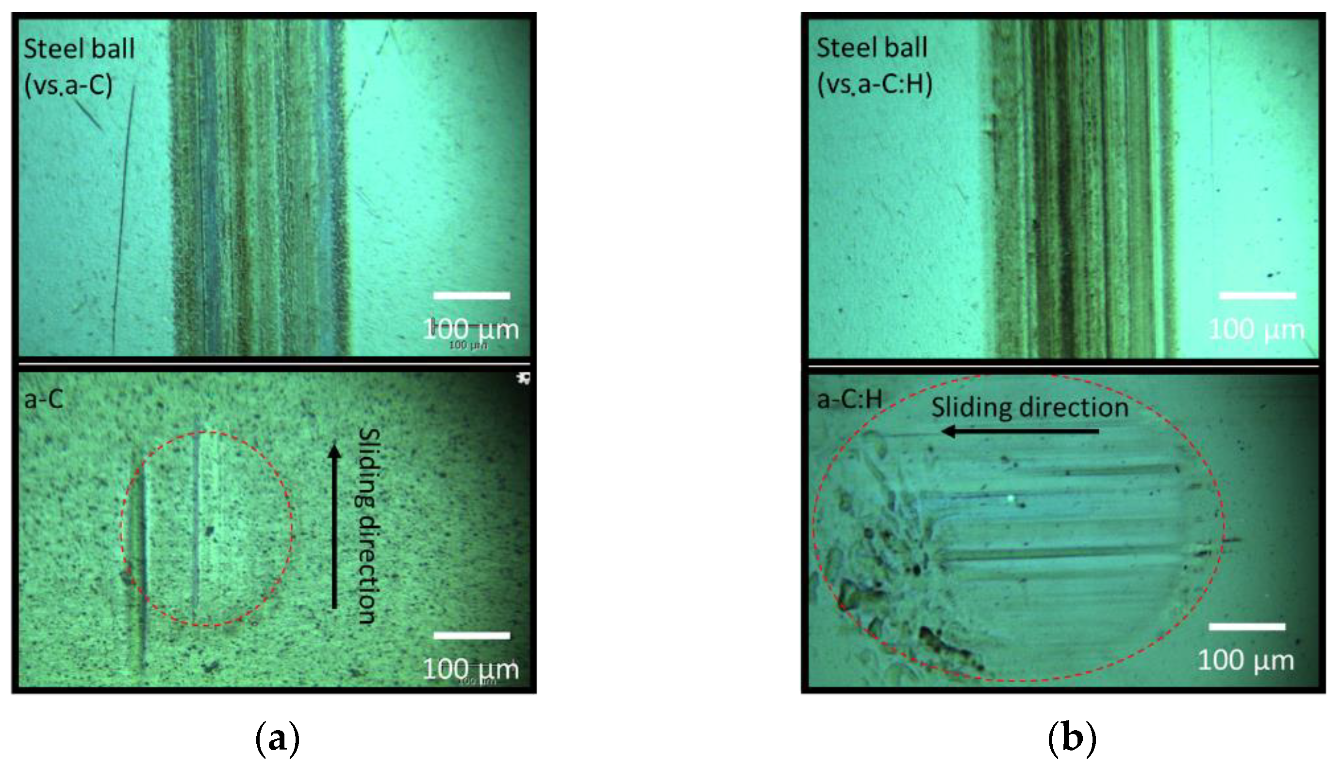
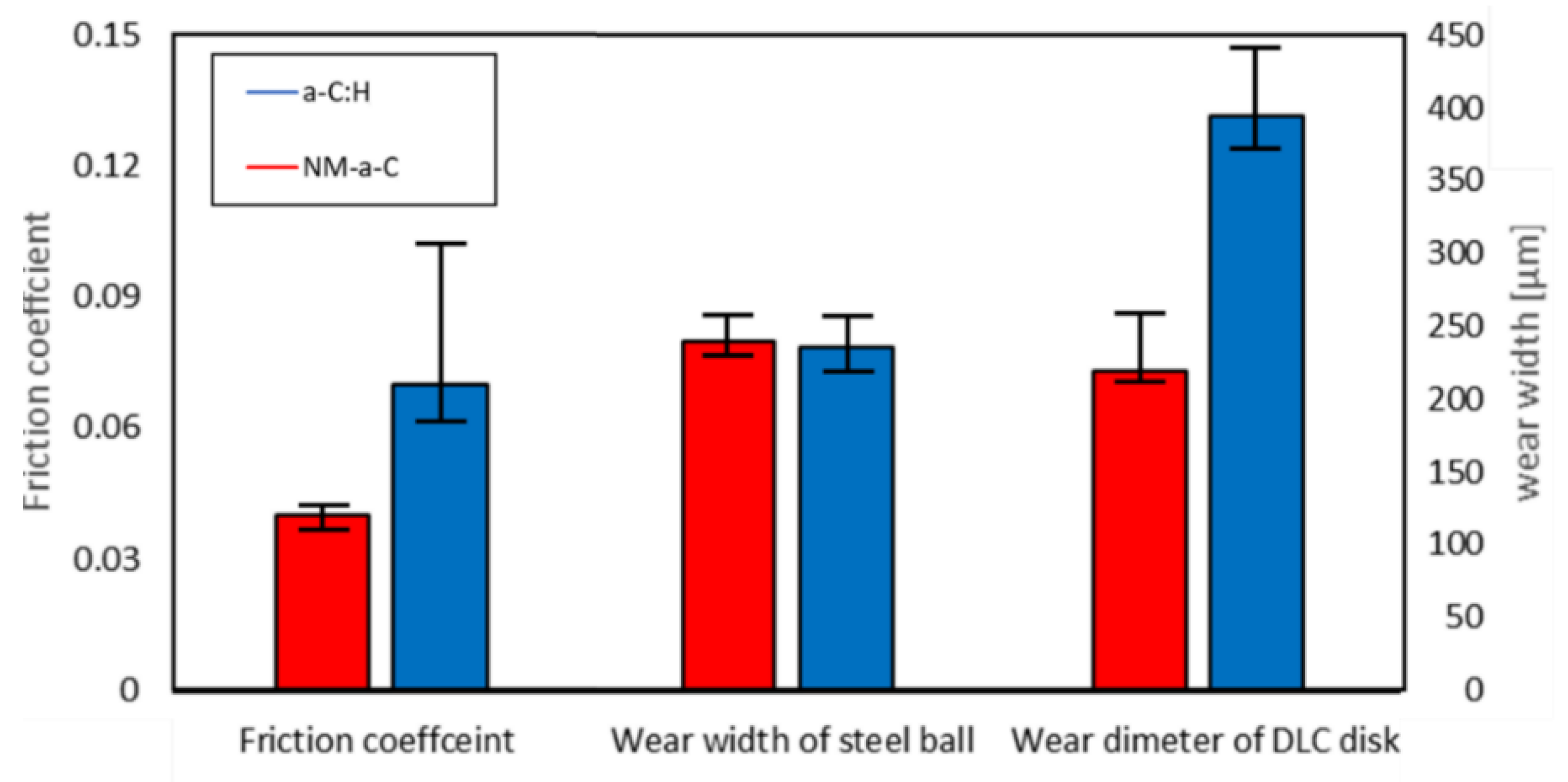
Figure 9 shows the frictional behavior of the DLC/steel (disk/ball) contacts when lubricated with the fully formulated oil containing both MoDTC and ZDDP. For the a-C:H/steel tribopairs, the friction coefficient dramatically initially decreased from 0.1 to 0.058 during the first 700 s. However, the frictional behavior was very unstable after this initial period, the friction coefficient settled at 0.06 by the end of the friction test. For the NM-a-C/steel tribopairs, the friction coefficient gradually decreased from 0.05 to 0.03 during the initial period of 1200 s. After this initial period, the friction behavior stabilized, finally assuming a value of 0.035. Figure 10 shows the worn surface of the test specimens. The specific difference was observed for the worn surface of the DLC disks and can be seen in Figure 10a,b; the size of the wear scar on the NM-a-C disk was significantly smaller than that on the a-C:H disk, although the wear width of the steel ball was nearly identical. Figure 11 shows the average friction coefficient during the last 5 min of the experiment over the wear width of the steel ball and the wear diameter of the DLC disks. From these results, the NM-a-C/steel tribopairs exhibited lower friction and wear properties than the a-C:H/steel tribopairs when lubricated with the fully formulated oil.

3.3. SLIM Analysis Results

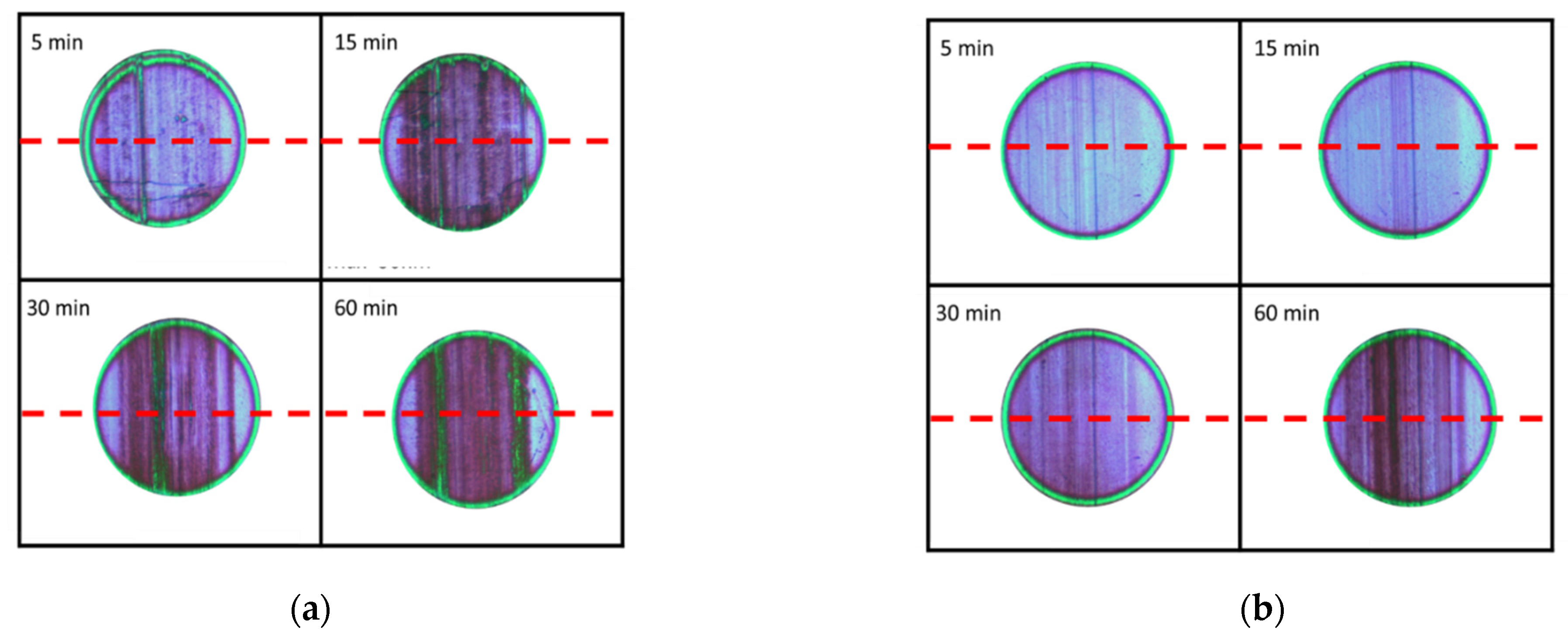
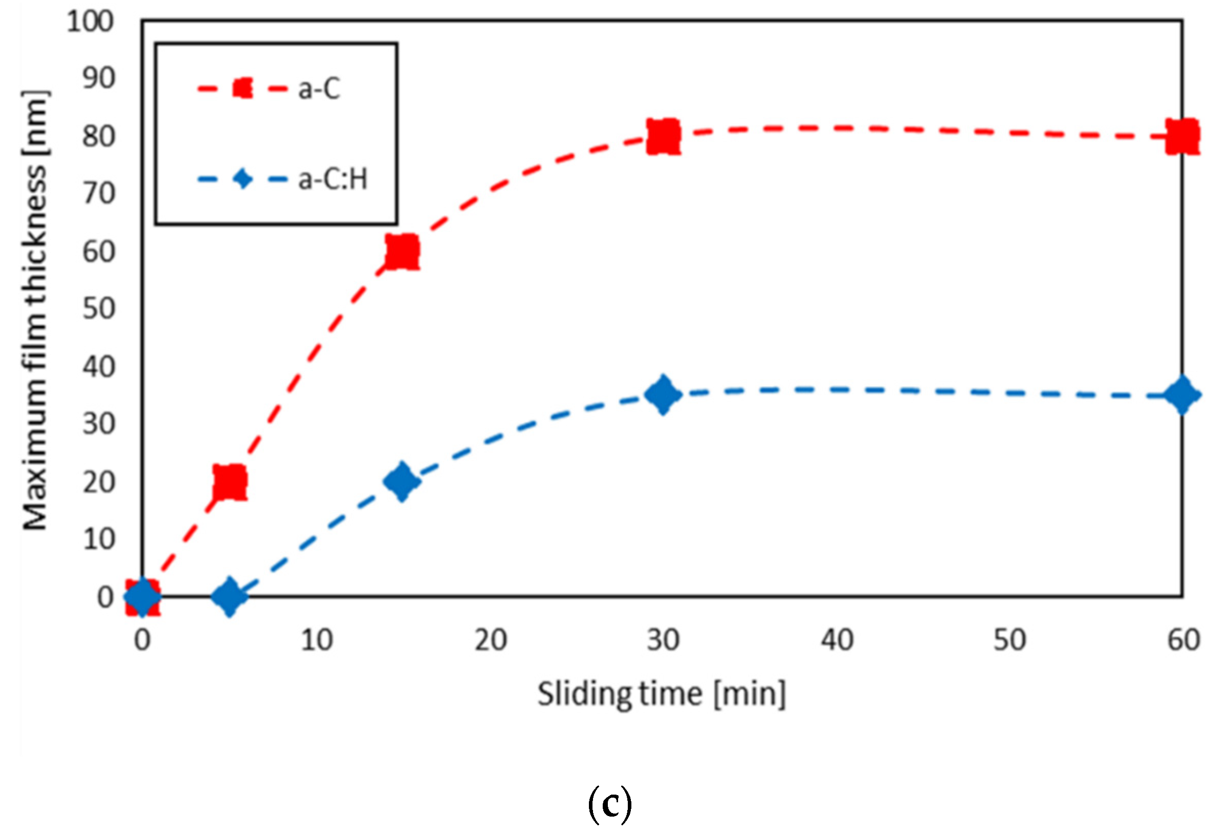
The SLIM images at 5, 15, 30, and 60 min and the maximum film thickness behavior as a function of sliding time are shown in Figure 12. As can be seen in Figure 12a,b, there was a distribution of the color of the SLIM interference images for both tribopairs. This indicates that the tribofilm did not form uniformly. For the NM-a-C/steel tribopairs, as shown in Figure 12a, SLIM image colors partially shifted from red to green. This indicates that lubricant additive-derived tribofilms grew within that area. For the a-C:H/steel tribopairs, as shown in Figure 12b, the color change was barely observed at the contact area in the friction test. Therefore, the tribofilm hardly grew up on the a-C:H/steel tribopairs. From these results, the tribofilm growth behavior strongly depends on the counter-face DLC structure under the condition of boundary lubrication.

3.4. Raman Analysis Results

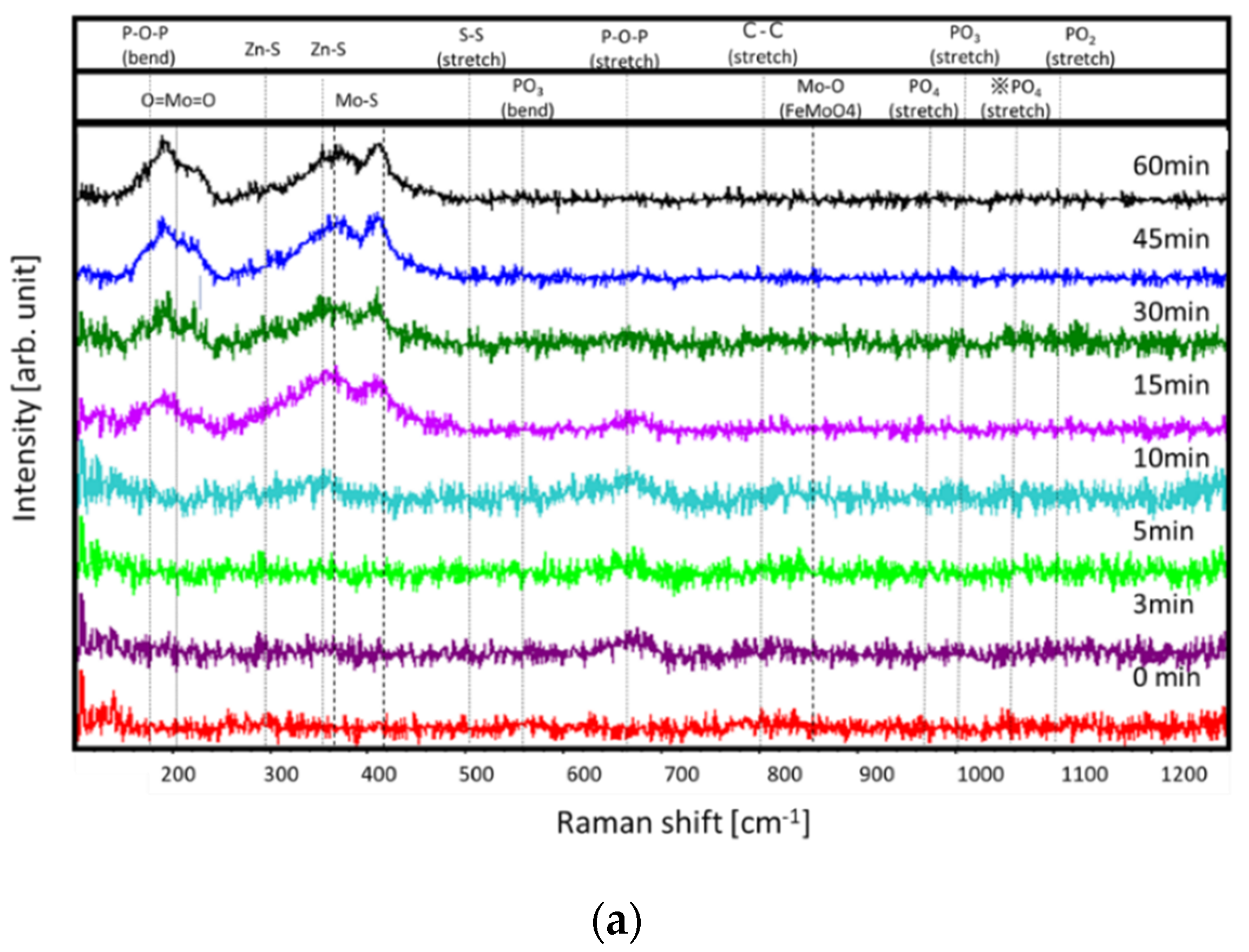
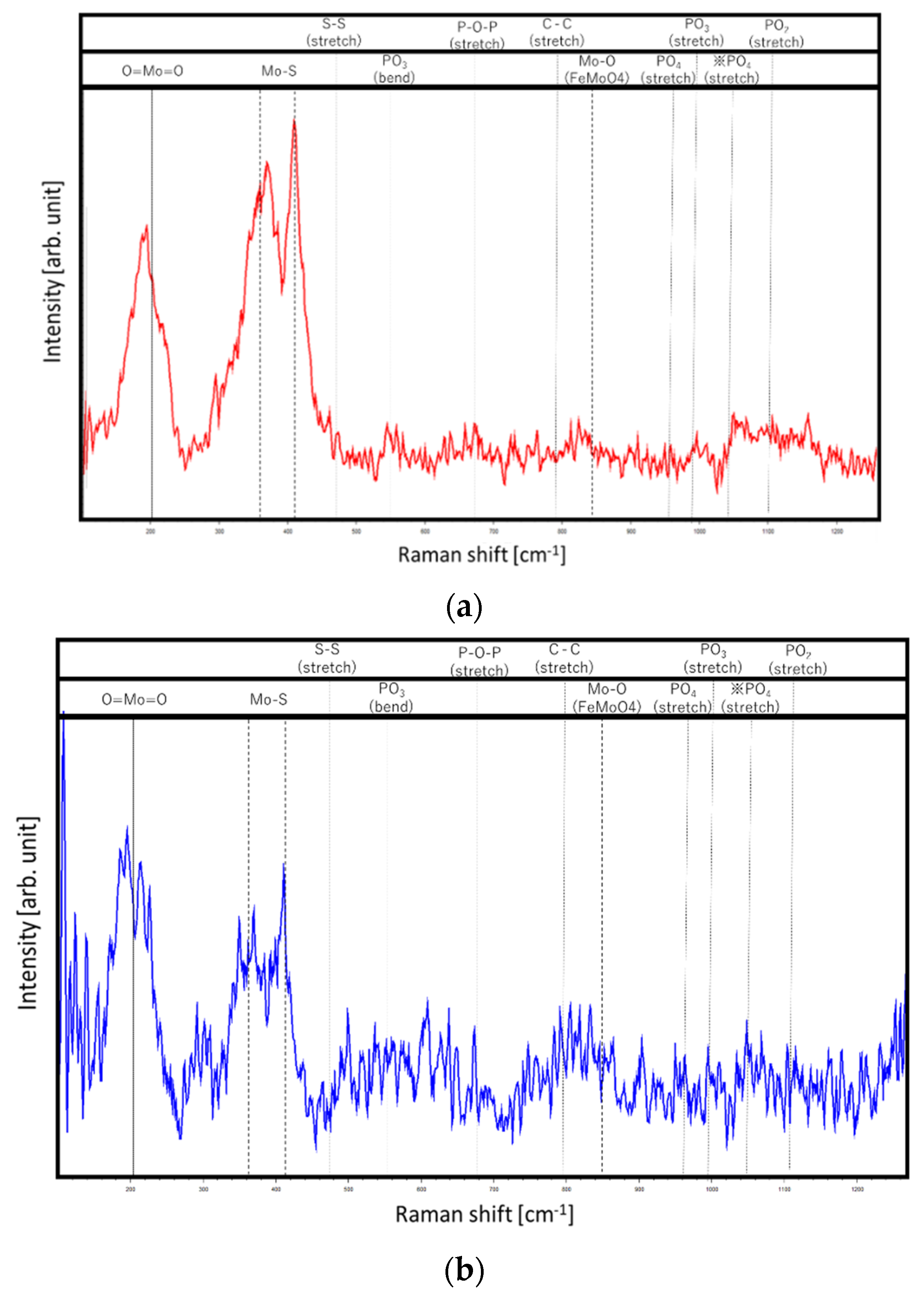
Figure 13 shows the in situ Raman spectra within the range of 100–1300 cm−1 for both tribopairs at 0, 3, 5, 10, 15, 30, 45, and 60 min. It is difficult to see the peaks in detail within Figure 13; therefore, we redisplayed the 60 min Raman spectra for both tribopairs as representative spectra in Figure 14. As shown in Figure 13 and Figure 14, MoS2 peaks at 380 and 410 cm−1 [14], and Mo-oxides (O = Mo = O) peaks at around 200 cm−1 were clearly observed from 15 to 60 min for both tribopairs [15]. For both tribopairs, slight broad phosphate compound peaks were observed for PO2, PO3, and PO4 stretching vibration at 1085, 980, and 910 cm−1, respectively [16,17]. PO3 and PO4 bending vibration peaks and P-O-P stretching vibration broad peaks were also observed at 525, 440, and around 700 cm−1 beginning at 30 min [16,17]. These results indicate that the MoDTC- and ZDDP-derived compounds such as MoS2, MoOx, and POx gradually formed on the steel surface for both tribopairs, and the peak intensity behavior might strongly relate to the increment in the film thickness of the tribofilm. Additional details will be discussed in the next section.

3.5. Lubrication Mechanism of the NM-a-C Film Lubricated with the Fully Formulated Oil

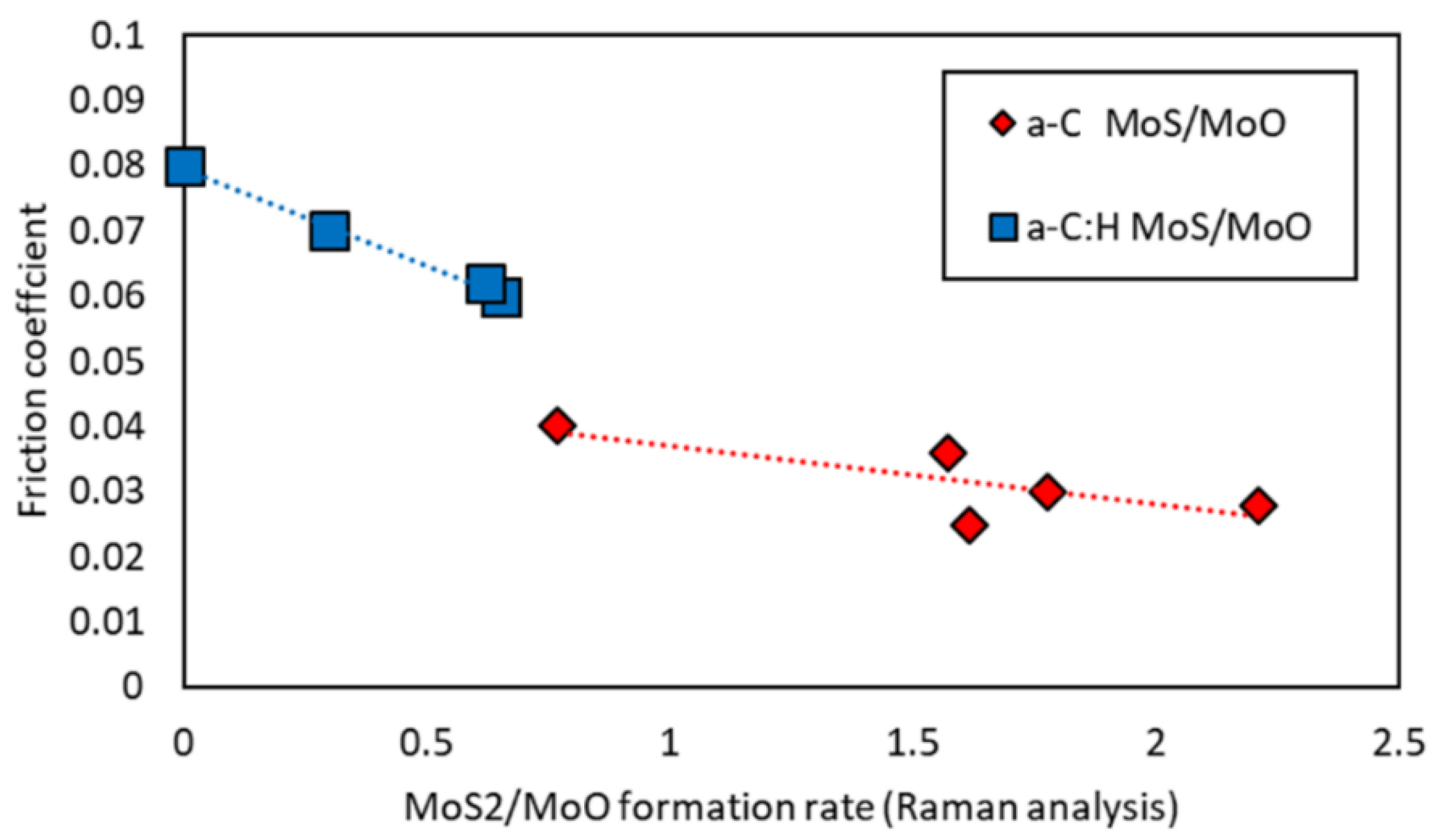
Herein, we investigated the tribological properties of a novel DLC with a mesh-structured layer when lubricated with fully formulated oil. The NM-a-C film exhibited lower friction and higher anti-wear performance when compared to the a-C:H film, although the mechanical properties of the DLC films were nearly identical as shown in Figure 7 and Figure 8. Hence, the difference between the tribological properties of NM-a-C and the a-C:H film is likely due to different tribofilm characteristics at the sliding contact. SLIM and in situ Raman analysis results (Figure 12 and Figure 13) revealed the difference in thickness and chemical composition of the tribofilm for the NM-a-C/steel and a-C:H/steel tribopairs. Regarding frictional properties, it is well-known that the MoDTC-derived MoS2 formation plays a critical role in frictional performance under boundary lubrication conditions; furthermore, the MoS2/MoOx formation rate on tribofilms significantly affects frictional performance [18,19]. From the in situ Raman analysis results, we calculated the MoS2/MoOx formation rate by the peak height ratio of Mo-S (410 cm−1) and O = Mo = O (210 cm−1); this behavior is highlighted in Figure 15. For the NM-a-C/steel tribopairs, the MoS2/MoOx formation rate dramatically increased to approximately 2.0 until roughly 15 min. After the onset period, the formation rate gradually decreased and finally reached a value of 1.6 by the end of the friction test. This behavior indicates that the MoS2 exists at a concentration 1.5–2.0 times higher than MoOx within the tribofilms. On the contrary, for the a-C:H/steel tribopairs, the MoS2/MoOx formation rate gradually increased and finally reached a stable value of 0.6. From these results, the MoS2-rich tribofilm formed on the interface of the NM-a-C/steel tribopairs, whereas the MoOx-rich tribofilm formed on the interface of a-C:H/steel tribopairs. Figure 16 shows the relationship between the formation rate of MoS2/MoOx and the friction coefficient for both tribopairs. It is worth noting from Figure 16 that the friction coefficient linearly decreased with each increment in the MoS2/MoOx formation rate for both tribopairs. Therefore, MoS2-richer tribofilms exhibit the lowest friction performance of the DLC/steel tribopairs when lubricated with fully formulated oils; the NM-a-C surface promotes the formation of MoS2 at the frictional sliding interface.
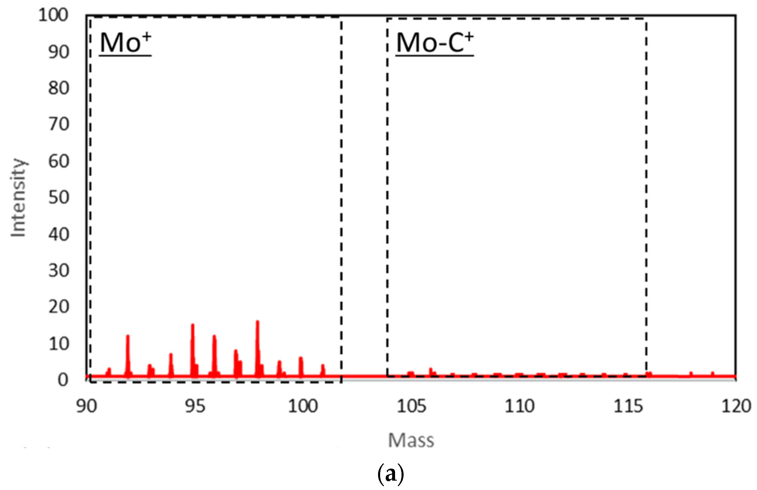
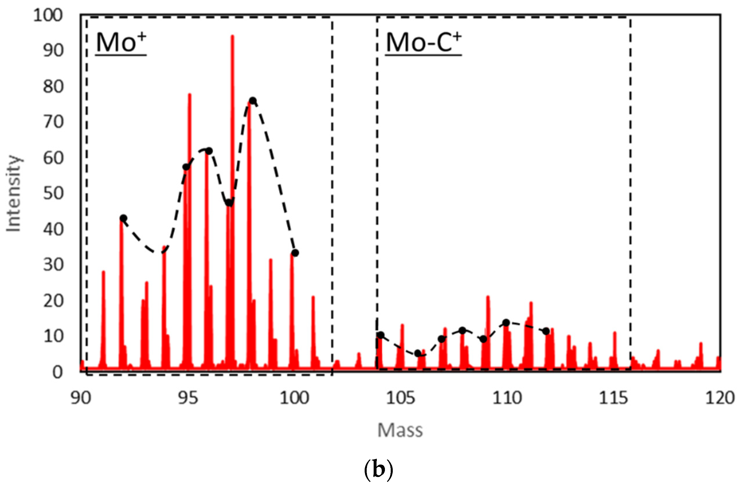
Regarding the wear properties of DLC films lubricated with a MoDTC solution, the formation of Mo-carbides at the frictional sliding interface contributes to the wear performance of the DLC films since the carburization of MoDTC decompositions causes chemical and abrasive wear on DLC films [11,20]. Therefore, the formation of Mo-carbides on DLC surfaces was confirmed via ToF-SIMS [11]. Figure 17 shows the ToF-SIMS mass spectra of the worn surface on both the NM-a-C and the a-C:H surfaces after the friction test. The ToF-SIMS positive ion spectra of mass numbers from 90 to 115 correspond to the masses of Mo+ and Mo-C+ fragments, of the seven well-known naturally-existing Mo isotopes: Mo92, Mo94, Mo95, Mo96, Mo97, Mo98, and Mo100. Observable in Figure 17, the behavior of the Mo+ isotope peak intensities for the a-C:H surface corresponded well with the behavior of Mo-C+ peak intensity: Mo-C104, Mo-C106, Mo-C107, Mo-C108, Mo-C109, Mo-C110, and Mo-C112; this is indicative of the Mo-C compounds formed at the sliding interface for the a-C:H/steel tribopairs. The Mo-C ion mass signature was hardly observed on the NM-a-C surface, indicating that Mo-carbides rarely formed at the NM-a-C/steel tribopair interface. Based on these results, the inhabitation of the Mo-carbide formation at the sliding interface is a contributing factor to the increased anti-wear performance of NM-a-C films when lubricated with a fully formulated oil containing MoDTC.
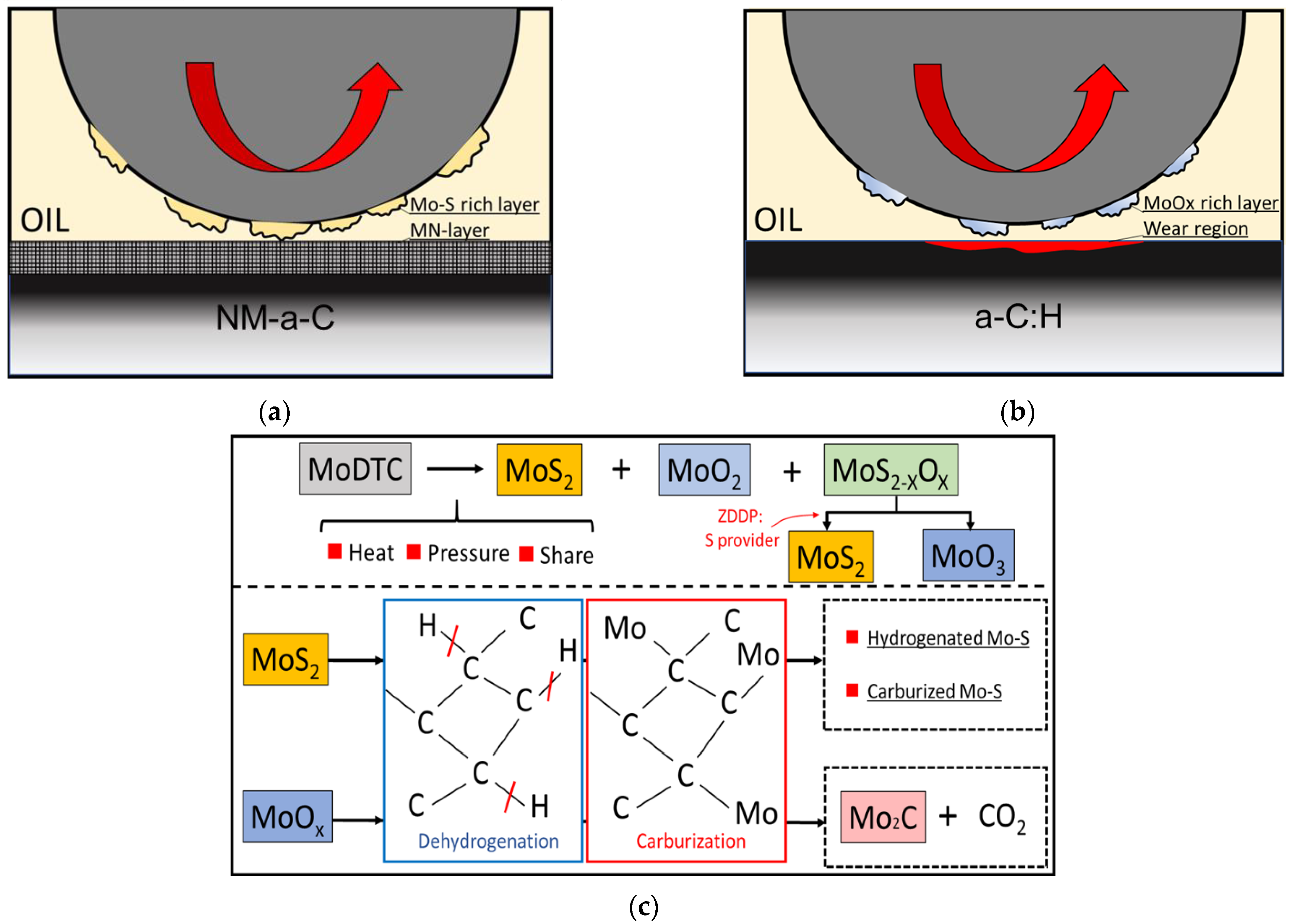
The lubricating mechanism of the NM-a-C/steel and a-C:H/steel tribopairs lubricated with the fully formulated oil containing MoDTC and ZDDP is illustrated in Figure 18. As indicated in Figure 18a,b and by the in situ Raman analysis results, the MoS2-rich tribofilm and MoOx-rich tribofilm form at the NM-a-C:H/steel and a-C:H/steel contacts, respectively. The difference in the tribofilm chemical composition is explainable by the role of hydrogen in the DLC film. MoDTC is decomposed to MoS2, MoOx, and MoS2-xOx at the tribological contacts [18]. It is known that MoS2 and MoOx have dehydrogenation catalytic activity for both hydrocarbon gases and oils [21,22,23]. Moreover, Mo-compounds readily react with hydrocarbon gases, and then Mo-carbide compounds are synthesized under static conditions [24]. The dehydrogenation and carburization processes can occur simultaneously at the interfacial tribological contact. Thus, the dehydrogenation process proceeds as follows: MoS2 and MoOx break C-H bonds on the surface of the a-C:H film, then the dangling carbon bond is exposed to the frictional sliding surface. The dangling bond can then react with the Molybdenum compounds, resulting in the formation of Mo-carbides. This two-step process both breaks down a-C:H structures and disturbs low-frictional MoS2 lamellar structures, since MoS2 is hydrogenated and carburized during the processes [21,22,23]; these disordered MoS2 structures do not show the friction-reducing effects of the ordered original, indicating the difficulty for MoDTC to supply low-friction MoS2 at the a-C:H/steel tribological interface. The frictional behavior for a-C:H/steel tribopairs is very unstable, with a friction coefficient higher than that of NM-a-C/steel tribopairs as shown in Figure 9. Moreover, the higher friction of the a-C:H/steel tribological interface likely contributed to an acceleration of the MoS2 oxidation reaction; the formation of the MoOx-rich tribofilm at the a-C:H/steel tribological interface can be explained by the above hypothesis. On the other hand, the dehydrogenation process for the NM-a-C/steel tribopairs cannot occur since the NM-a-C contains very little hydrogen, as can be seen in the ERDA results shown in Figure 5. Therefore, MoDTC-derived Mo-compounds are generally inert at the NM-a-C surface of tribological contacts, resulting in the inhibition of Mo-carbide formation (Figure 17). The inhibition of the dehydrogenation and carburization processes contributed to the characteristic low frictional MoS2-rich layer of NM-a-C/steel tribological contacts (Figure 12 and Figure 16). Regarding the low frictional mechanism of the NM-a-C/steel tribopair, there is another possibility that the NM-a-C surface with a micro-graphite sp2 structure (as shown in Figure 4) promotes the formation of the MoS2-rich layer due to hetero-epitaxial growth, which is a well-known phenomenon for synthesizing MoS2/Graphene hybrid heterostructures in a static synthesis condition [25]. Additional experiments will be needed to prove the hypothesis.
In summary, our results suggest that NM-a-C films exhibit greater tribological performance compared to a-C:H films in fully formulated oils containing MoDTC under boundary lubrication conditions; furthermore, NM-a-C films display great potential as a new tribological coating in automotive engine components. However, the roles of the mesh-like layer of the NM-a-C for the tribological behavior and the tribofilm formation have not been revealed. Therefore, further study is needed to evaluate the properties of the mesh-like layer using a Calo tester, scratch tester, and nano-indenter, and so on.

4. Conclusions

Herein, we investigated the tribological properties of a mesh-like nanostructured diamond-like carbon (DLC) coating lubricated with a fully formulated oil at DLC/steel contacts via an in situ Raman-SLIM tribometer.
  • From our SEM, ERDA, and XPS analyses, the NM-a-C film is characterized as non-hydrogenated amorphous carbon, and possesses a nano-mesh-like structured layer at the outermost surface.
  • The results of our friction tests indicate that the NM-a-C exhibited lower friction and higher wear resistance than the a-C:H under lubrication with a fully formulated oil containing MoDTC and ZDDP.
  • The in situ Raman-SLIM and ToF-SIMS results indicated that thicker MoS2-rich tribofilms form on the counter-face steel surface as opposed to the NM-a-C film. Additionally, the NM-a-C and steel interface inhibited the formation of Mo-carbides, contributing to DLC wear.
  • Differences in the tribological properties between the NM-a-C/steel and the a-C:H/steel tribopairs can be explained by the difference between the tribofilms within DLC films, caused by dehydrogenation and carburization between MoDTC decompositions and the DLC surface. The NM-a-C film was observed to be mostly inert to MoDTC-derived Mo-compounds at tribological contacts. Due to the inhibition of the dehydrogenation and carburization processes, tribofilms with low frictional MoS2-rich layers survive and develop at the NM-a-C/steel tribological contacts, resulting in both low friction and high-wear-resistance performance under boundary lubrication regimes.

Author Contributions

All authors contributed to the conception and design of this study. Material preparation, data collection, and analysis were performed by H.O. The first draft of the manuscript was written by H.O. All authors commented on draft versions of the manuscript and read and approved the final manuscript. All authors have read and agreed to the published version of the manuscript.

Funding

This research received no external funding.

Institutional Review Board Statement

Not applicable.

Informed Consent Statement

Not applicable.

Data Availability Statement

The data presented in this study are available on request from the corresponding author.

Conflicts of Interest

The authors declare no conflict of interest.

References

  1. Holmberg, K.; Erdemier, A. Influence of tribology on global energy consumption, costs and emissions. Friction 2017, 5, 263–284. [Google Scholar] [CrossRef]
  2. De Barros’Bouchet, M.I.; Martin, J.M.; Le-Mogne, T.; Vacher, B. Boundary lubrication mechanisms of carbon coatings by MoDTC and ZDDP additives. Tribol. Int. 2005, 38, 257–264. [Google Scholar] [CrossRef]
  3. Haque, T.; Morina, A.; Neville, A.; Kapadia, R.; Arrowsmith, S. Non-ferrous coating/lubricant interactions in tribological contacts: Assessment of tribo-films. Tribol. Int. 2007, 40, 1603–1612. [Google Scholar] [CrossRef]
  4. Miyake, S.; Saito, T.; Yasuda, Y.; Okamoto, Y.; Kano, M. Improvement of boundary lubrication properties of Diamond-Like Carbon (DLC) films due to metal addition. Tribol. Int. 2004, 37, 751–761. [Google Scholar] [CrossRef]
  5. Okubo, H.; Sasaki, S.; Lancon, D.; Jarnias, F.; Thiébaut, B. Tribo-Raman-SLIM observation for diamond-like carbon lubricated with fully formulated oils with different wear levels at DLC/steel contacts. Wear 2020, 454–455, 203326. [Google Scholar] [CrossRef]
  6. Vengudusamy, B.; Green, J.H.; Lamb, G.D.; Spikes, H.A. Behaviour of MoDTC in DLC/DLC and DLC/Steel contacts. Tribol. Int. 2012, 54, 68–76. [Google Scholar] [CrossRef]
  7. Vengudusamy, B.; Green, J.H.; Lamb, G.D.; Spikes, H.A. Tribological properties of tribofilms formed from ZDDP in DLC/DLC and DLC/steel contacts. Tribol. Int. 2011, 44, 165–174. [Google Scholar] [CrossRef]
  8. Mabuchi, Y.; Higuchi, T.; Weihnacht, V. Effect of sp2/sp3 Bonding ratio and nitrogen content on friction properties of hydrogen-free DLC coatings. Tribol. Int. 2013, 62, 130–140. [Google Scholar] [CrossRef]
  9. Aisenberg, S.; Chabot, R. Ion-beam deposition of thin films of diamondlike carbon. J. Appl. Phys. 1971, 42, 2953–2958. [Google Scholar] [CrossRef]
  10. Moriguchi, H.; Shibata, A.; Watanabe, J. Tribological Properties of New Type DLC Film “Geniuscoat HAM”. Nissin Electr. 2017, 62, 1–6. Available online: https://nippon-itf.co.jp/technology/pdf/NEGIHO.pdf (accessed on 27 April 2021).
  11. Okubo, H.; Watanabe, S.; Tadokoro, C.; Sasaki, S.; Sumi, T.; Tanaka, N. Wear acceleration mechanism of diamond-like carbon (DLC) films lubricated with MoDTC solution: Roles of tribofilm formation and structural transformation in wear acceleration of DLC films lubricated with MoDTC solution. Tribol. Int. 2019, 133, 271–287. [Google Scholar] [CrossRef]
  12. Okubo, H.; Yonehara, M.; Sasaki, S. In-situ raman observations of the formation of MoDTC-derived tribofilms at steel/steel contact under boundary lubrication. Tribol. Trans. 2018, 61, 1040–1047. [Google Scholar] [CrossRef]
  13. Díaz, J.; Paolicelli, G.; Ferrer, S.; Comin, F. Separation of the sp3 and sp2 components in the C 1s photoemission spectra of amorphous carbon films. Phys. Rev. B 1996, 54, 8064. [Google Scholar] [CrossRef]
  14. Khaemba, D.N.; Neville, A.; Morina, S. New insights on the decomposition mechanism of molybdenum DialkyldiThioCarbamate (MoDTC): A raman spectroscopic study. RSC Adv. 2016, 45, 38637–38646. [Google Scholar] [CrossRef] [Green Version]
  15. Dieterle, M.; Weinberg, G.; Mestl, G. Raman spectroscopy of molybdenum oxides. Phys. Chem. 2002, 4, 812–821. [Google Scholar] [CrossRef]
  16. Zhang, L.; Brow, R.K. A Raman study of iron–phosphate crystalline compounds and glasses. J. Am. Ceram. Soc. 2011, 94, 3123–3130. [Google Scholar] [CrossRef]
  17. Vedeanu, N.; Cozar, O.; Ardelean, I.; Lendl, B. IR and raman investigation of x(CuO·V2O5)(1-x) [P2O5·CaF2] glass system. J. Optoelectron. Adv. Mater. 2006, 8, 78–81. [Google Scholar]
  18. De Barros’Bouchet, M.I.; Martin, J.M.; Le-Mogne, T.; Vacher, B.; Yamada, Y. Mechanisms of MoS2 formation by MoDTC in presence of ZnDTP: Effect of oxidative degradation. Wear 2005, 258, 1643–1650. [Google Scholar] [CrossRef]
  19. Morina, A.; Neville, A.; Priest, M.; Green, J.H. ZDDP and MoDTC interactions in boundary lubrication-the effect of temperature and ZDDP/MoDTC ratio. Tribol. Int. 2006, 39, 1545–1557. [Google Scholar] [CrossRef]
  20. De Feo, M.; De Barros Bouchet, M.I.; Minfray, C.; Esnouf, C.; Le Mognea, T.; Meunier, F.; Yang, L.; Thiebaut, B.; Pavan, S.; Martin, J.M. Formation of interfacial molybdenum carbide for DLC lubricated by MoDTC: Origin of wear mechanism. Wear 2017, 370–371, 17–28. [Google Scholar] [CrossRef] [Green Version]
  21. Sugioka, M.; Kimura, F. Oxidation and reduction of molybdenum disulfide catalyst and their effects on the decomposition of 2-propanol. Sekiyu Gakkai Shi 1985, 28, 306–311. [Google Scholar] [CrossRef] [Green Version]
  22. Travert, A.; Nakamura, H.; van Santen, R.A.; Cristol, S.; Paul, J.F. Hydrogen activation on mo-based sulfide catalysts, a periodic DFT study. J. Am. Chem. Soc. 2002, 7084–7095, 17–28. [Google Scholar] [CrossRef] [PubMed]
  23. Kosarieh, S.; Morina, A.; Laine, E.; Flemming, J.; Neville, A. Wear mechanisms of hydrogenated DLC in oils containing MoDTC. Tribol. Int. 2016, 64, 4. [Google Scholar] [CrossRef] [Green Version]
  24. Xiao, T.-C.; York, A.P.E.; Williams, V.C.; Al-Megren, H.; Hanif, A.; Zhuo, X.-Y.; Green, M.L.H. Preparation of molybdenum carbides using butane and their catalytic performance. Chem. Mater. 2000, 12, 3896–3905. [Google Scholar] [CrossRef]
  25. Shi, Y.; Zhou, W.; Lu, A.-Y.; Fang, W.; Lee, Y.-H.; Hsu, A.L.; Kim, S.M.; Kim, K.K.; Yang, H.Y.; Li, L.-J.; et al. van der Waals epitaxy of MoS2 layers usingg as growth templates. Nano Lett. 2012, 12, 2784–2791. [Google Scholar] [CrossRef]
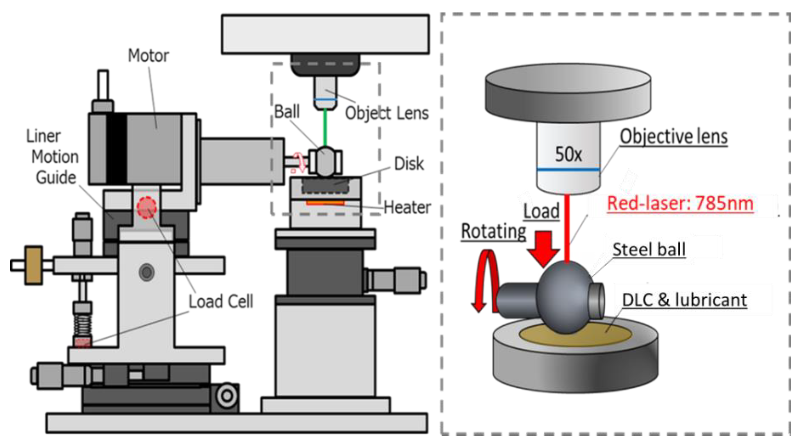
Figure 1. Schematic diagram of the in situ Raman-SLIM tribometer.
Coatings 11 00746 g001
Figure 2. Schematic diagram of (a) the in situ Raman and (b) in situ SLIM analysis.
Coatings 11 00746 g002
Figure 3. Deposition temperature of the DLCs: (a) NM-a-C and (b) Conventional DLC.
Coatings 11 00746 g003
Figure 4. TEM image of the FIB prepared cross-sectional of (a) the NM-a-C and (b) the conventional DLC films [10].
Coatings 11 00746 g004
Figure 5. ERDA hydrogen concentration analysis results for the as-deposited DLC films as a function of the analytical depth.
Coatings 11 00746 g005
Figure 6. Typical XPS C1s spectra of the as-deposited DLC films.
Coatings 11 00746 g006
Figure 7. Nano-indentation results of the as-deposited DLC films.
Coatings 11 00746 g007
Figure 8. Optical microscopic images and the surface roughness parameter, Sa of (a) the as-deposited NM-a-C and (b) as-deposited a-C:H DLC films and AFM topographical images (5 × 5 μm scan size) and the surface roughness parameter, Sa, of (c) the as-deposited NM-a-C and (d) as-deposited a-C:H DLC films.
Coatings 11 00746 g008
Figure 9. Frictional behavior of the DLC/steel (disk/ball) contacts when lubricated with the fully formulated oil containing both MoDTC and ZDDP.
Coatings 11 00746 g009
Figure 10. Optical images of the worn surface for (a) the NM-a-C/steel tribopair and (b) a-C:H/steel tribopair.
Coatings 11 00746 g010
Figure 11. Average friction coefficient during the last 5 min of the experiment over the wear width of the steel ball and the wear diameter of the DLC disks.
Coatings 11 00746 g011
Figure 12. SLIM interference images of the steel ball for (a) the NM-a-C/steel and (b) the a-C:H/steel tribopairs at 5, 15, 30, and 60 min and (c) the maximum film thickness behavior as a function of sliding time as calculated from the center red line.
Coatings 11 00746 g012aCoatings 11 00746 g012b
Figure 13. In situ Raman spectra within the range of 100–1300 cm−1 obtained from the steel surface for (a) NM-a-C/steel and (b) a-C:H/steel tribopairs at 0, 3, 5, 10, 15, 30, 45, and 60 min.
Coatings 11 00746 g013aCoatings 11 00746 g013b
Figure 14. Representative Raman spectra obtained from the steel surface for (a) NM-a-C/steel and (b) a-C:H/steel tribopairs.
Coatings 11 00746 g014
Figure 15. Time-dependence behavior of the MoS2/MoOx formation rate by the peak height ratio of Mo-S (410 cm−1) and O = Mo = O (210 cm−1) in the in situ Raman spectra.
Coatings 11 00746 g015
Figure 16. Relationship between the formation rate of MoS2/MoOx and the friction coefficient for both tribopairs.
Coatings 11 00746 g016
Figure 17. ToF-SIMS positive ion spectra of mass numbers from 90 to 115 correspond to the masses of Mo+ and Mo-C+ fragments obtained from (a) the a-C:H and (b) NM-a-C worn surfaces.
Coatings 11 00746 g017aCoatings 11 00746 g017b
Figure 18. Lubricating mechanism of (a) the NM-a-C/steel and (b) a-C:H/steel tribopairs lubricated with the fully formulated oil containing MoDTC and ZDDP and (c) the chemical reaction processes between the MoDTC and hydrogenated DLC.
Coatings 11 00746 g018
Table 1. XPS C1s analytical results of both as-deposited DLC films.
BandPosition
[cm−1]
FWHM
[cm−1]
Areasp3/(sp2 + sp3)
[%]
NM-a-Csp2284.51.6347,82148.5
sp3285.33.1145,089
a-C:Hsp2284.51.3850,24850
sp3285.3251,199
Publisher’s Note: MDPI stays neutral with regard to jurisdictional claims in published maps and institutional affiliations.