Abstract
At present, hard coating structures are widely studied as a new passive damping method. Generally, the hard coating material is completely covered on the surface of the thin-walled structure, but the local coverage cannot only achieve better vibration reduction effect, but also save the material and processing costs. In this paper, a topology optimization method for hard coated composite plates is proposed to maximize the modal loss factors. The finite element dynamic model of hard coating composite plate is established. The topology optimization model is established with the energy ratio of hard coating layer to base layer as the objective function and the amount of damping material as the constraint condition. The sensitivity expression of the objective function to the design variables is derived, and the iteration of the design variables is realized by the Method of Moving Asymptote (MMA). Several numerical examples are provided to demonstrate that this method can obtain the optimal layout of damping materials for hard coating composite plates. The results show that the damping materials are mainly distributed in the area where the stored modal strain energy is large, which is consistent with the traditional design method. Finally, based on the numerical results, the experimental study of local hard coating composites plate is carried out. The results show that the topology optimization method can significantly reduce the frequency response amplitude while reducing the amount of damping materials, which shows the feasibility and effectiveness of the method.
1. Introduction
Hard coating is a kind of coating material made of metal base, ceramic base, or both. It is mainly used for thermal barrier, friction resistance, and corrosion resistance coating [1,2,3]. In recent years, it has been found that the hard coating also has the effect of damping and vibration reduction, which shows that spraying hard coating on the structure surface can significantly reduce the resonance stress amplitude of the thin walled structure [4,5,6,7]. Furthermore, it was found that the reason why the hard coating can reduce the vibration is due to the internal friction between the hard coating particles [8,9,10,11,12,13]. Several microscopic material characterization models have been created to explain the vibration reduction mechanism of the hard coating [14,15,16]. The existing research on the vibration reduction mechanism of hard coatings mostly focus on micro materials. However, it is not enough to study the mechanism of hard coating from the perspective of hard coating dynamics. When the hard coating is completely deposited on the surface of the structure, only a part of the coating material can reduce the vibration amplitudes, and other materials will only increase the additional mass, and will not reduce the vibration amplitudes. Therefore, partially covered of hard coating and deposited in suitable positions seems more reasonable. It can be seen that, in order to effectively implement the hard coating vibration reduction, it is necessary to systematically study the dynamic modeling of the hard coating composite structure, but also to study the damping optimization problem of the hard coating composite structure.
The dynamic modeling and analysis of hard-coating composite structures have been widely and deeply studied. Yang et al. [17] derived the governing equation of the hard coated composite plate, and solved its inherent characteristics based on the perturbation method. Li et al. [18] studied the nonlinear vibration mechanism of hard coated cantilever thin plate structure and calculated its natural frequency and vibration response by finite element iteration method. Chen et al. [19] developed an analytical method to calculate the free vibration characteristics and damping effect of a hard coated blisk. The above modeling and analysis of hard coating composite structure mainly focuses on the fully coated structure, that is, the hard coating is completely applied in the coating area. The damping optimization of hard coating composite structure needs local coating model, but the research on modeling and analysis of local coating composite structure is not enough. As a new damping technology, the research on damping optimization of hard coating composite structure is rare, but similar to viscoelastic damping structure optimization, a lot of research has been carried out. Lumsdaine et al. [20,21] carried out shape optimization for beam and slab structures with the goal of minimizing peak displacement (or maximizing system loss factor). Chen et al. [22] took the structural damping of the system as the main performance index to optimize the layout of constrained damping materials. Hou et al. [23] used genetic algorithm to determine the optimal values of the thickness of the constrained layer and viscoelastic layer and the shear modulus of the viscoelastic layer. Aiming at minimizing the vibration response of cylindrical shells, Zheng et al. [24] adopted genetic optimization based on penalty function method to optimize the layout of passive constrained damping layer. With the gradual maturity of structural topology optimization technology [25,26]. The SIMP method and ESO method are applied to CLD processing structure design to achieve the optimal distribution of damping materials. Zheng et al. [27] and Zheng et al. [28] used SIMP method and moving asymptote method (MMA) to optimize modal damping ratio of rectangular plate treated by CLD. Fang and Zheng [29] established the topology optimization model of plate with ESO method and minimized the square of vibration response peak under the specified frequency band excitation.
The common coating deposition technologies include electroplating, chemical plating, chemical plating, thermal spraying, hot dipping, physical vapor deposition (PVD), chemical vapor deposition (CVD), chemical vapor deposition (CVD), molecular beam epitaxy (MBE), and ion beam synthesis. Among them, PVD and plasma spraying (PS) are commonly used in the preparation of alloy coatings. Additive manufacturing (AM) realizes the fabrication of structures by layer by layer accumulation of materials. This unique manufacturing method can realize the free growth forming of highly complex structures, greatly broaden the design space, and provide a powerful tool for the preparation of new structures and materials. The geometry of hard-coating thin walled structure obtained by topology optimization is complex, and the traditional coating preparation method cannot directly process according to the optimized geometry, so it is often necessary to cover the areas that don’t need coating. This approach undoubtedly causes material waste and time-consuming. The combination of additive manufacturing technology and topology optimization technology will facilitate the preparation of hard coatings with complex geometry. Metal powder and ceramic powder are manufactured by traditional technology, and then the powder is stacked according to the optimized geometry to form hard coating by additive manufacturing technology. With the development of rapid additive manufacturing technology [30], the application of this technology in the preparation of hard coating can not only achieve the purpose of material reduction, but also ensure the preparation efficiency and accuracy.
Hard coating structure and viscoelastic damping structure are all laminated thin-walled structures, which mainly involve the analysis and optimization of dynamic characteristics. The difficulty lies in the accurate calculation of modal damping and the sensitivity of objective function to design variables. Although some progress has been made in topology optimization of viscoelastic damped structures, there are still some problems that the sensitivity calculation is not accurate and the optimization results are not ideal, especially the topology optimization of constrained layer damping (CLD) structures. Hard damping structures are different from the CLD structures. The elastic modulus of hard coating is much higher than that of viscoelastic material, and the material loss factor is lower than that of viscoelastic material. Therefore, in composite structure modeling, the calculation of modal loss factor and the sensitivity of objective function to design variables will be different. In this paper, a simplified finite element model is established by considering the material parameters of hard coating composite structure. A calculation method of modal loss factor is proposed, and a simplified topology optimization model is obtained. The accuracy and efficiency of the proposed topology optimization design method are verified by experiments
2. Analytic Model
2.1. Dynamic Model
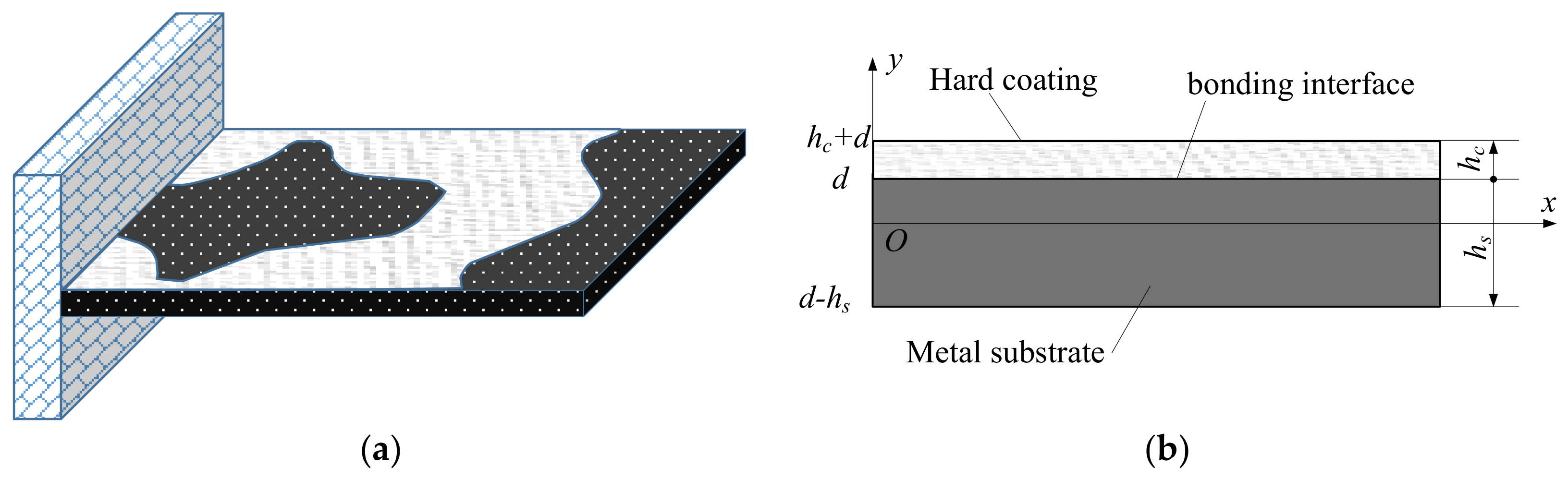
The structure of cantilever thin plate partially coated with hard coating damping material is shown in Figure 1a,b is the cross section of coating area of the thin plate. Hs and Hc are the thickness of the substrate and the hard coating respectively, and d is the distance from the joint surface of the hard coating and the substrate to the neutral layer of the composite structure. The y-axis coordinate of the upper surface of the composite plate is Hc + d, and the y-axis coordinate of the lower surface is . Although the internal damping of the hard coating is greater than that of the metal, it is far less than that of the viscoelastic damping material. In order to accurately describe the vibration characteristics of the coating structure, the internal damping of the metal matrix should also be considered. Here, the material parameters of hard coating and metal matrix are expressed by complex modulus.
where, , and , are the complex modulus of hard coating and matrix respectively and are the corresponding storage modulus and loss factor respectively.

Figure 1.
Thin plate structure with partially covered hard coating (a) cantilever composite plate, (b) cross section of coating area.
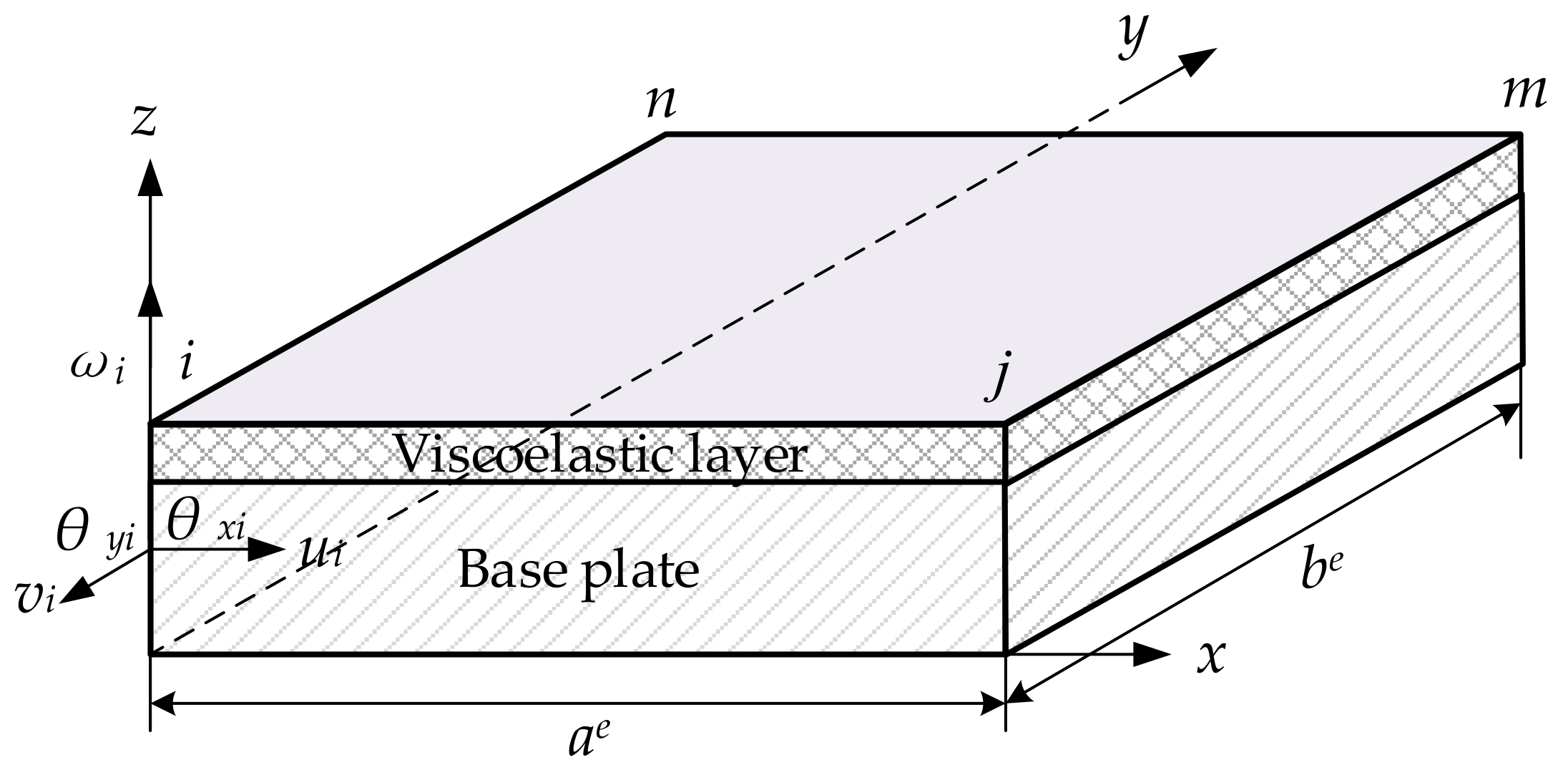
In this paper, the equivalent single layer theory is used for the finite element modeling. Since the hard coating is applied partially, when the hard coating plate is divided into several elements, there will be two types of elements in the whole system: hard-coating composite structure elements (including both substrate and coating) and substrate elements. For convenience, the four node plate elements are used to simulate the above two types of elements at the same time, but different material parameters are given. The specific structure of the elements is shown in Figure 2, each node has five degrees of freedom, including three degrees of freedom of translation and two degrees of freedom of rotation. Based on the Love Kirchhoff theory, the displacements of the base layer and the constraining layer at any point inside the element in the x- and y- directions are
where u, v, and w are the displacement components in the x-, y-, and z-directions, respectively, and u0, v0, and w0 are the midplane displacements. Z is the distance from the point to the middle surface
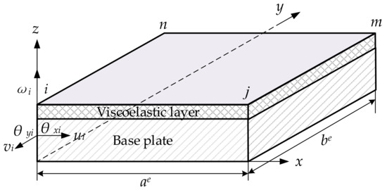
Figure 2.
Four node laminated rectangular element of hard coating plate.
Considering the constraints of structure performance and process conditions, the thickness of hard coating varies from 0.01% to 10% of the substrate thickness. Therefore, it can be approximately considered that the symmetrical central plane in the thickness direction of the composite plate is the neutral plane. In this study, before establishing the finite element dynamic model of composite plate, the following assumptions are made:
- each layer of material meets the basic assumptions of material mechanics, and the structural deformation is small deformation
- the base and hard coating meet the Kichhoff thin plate theory hypothesis
- ignore the shear deformation of base and hard coating
- ignore the moment of inertia of each layer of material
- The results show that the transverse displacement of the same coordinate position of each layer in Z direction is equal
- the bonding of materials in each layer is firm, and there is no relative sliding between layers.
is the displacement on the datum plane, then the strain vector at any point of the composite plate is:
Two-dimensional Hooke’s law can be used to express the stress-strain relationship at any point in the finite element of hard coated composite plate
Based on the theory of elastic plate and shell, the kinetic energy and strain potential energy of each layer of hard coated plate element are derived by energy method.
The kinetic energy of the base is as follows:
The kinetic energy of hard coating is as follows:
The strain potential energy of base course is as follows:
The strain potential energy of hard coating is as follows:
Therefore, the stiffness matrix and mass matrix of the element can be obtained as follows:
where B and N are strain displacement matrix and shape function matrix respectively. The global stiffness matrix and mass matrix can be obtained by assembling the element matrix as follows:
2.2. Damping Model
For a hard coated composite plate system under harmonic excitation, it is assumed that the energy stored in the plate structure system before coating is expressed as
where Ubmax is the maximum strain energy and Tbmax is the maximum kinetic energy. The energy consumed in one cycle of vibration can be expressed as
where is the energy consumption in the clamping area, is the material damping energy consumption, and is the energy consumption caused by the air. Therefore, the modal loss factor of the system before coating can be expressed as
The energy stored in the plate structure system after coating can expressed as
where , are the stored energy of the substrate and hard coating part. The energy consumed by the system after coating in one cycle is expressed as
where is the energy consumption caused by hard coating. Therefore, the modal loss factor of the plate system after coating can be expressed as
where, is the loss factor of the hard coating. is the loss factor of the composite structure system exclude the loss factor of the hard coating. For the maximum strain energy of the hard coating is much smaller than that of metal substrate, it can be approximately considered as .
3. Topology Optimization of the Hard Coating
3.1. Optimization Model
Assuming that is the variable, the partial derivative of modal loss factor of composite structure system with respect to is calculated as follows
Generally, the loss factor of hard coating damping material is slightly larger than that of base plate, so . In order to maximize the modal loss factor, the minimization of can be used as the objective function. Taking the relative density of hard coating finite element as design variable and volume percentage as constraint condition, the topology optimization mathematical model of hard coating structure system is established
where and are the finite element volume and design domain of the hard coating, is the volume ratio, is the relative density of the element.
According to the material interpolation theory of SIMP method, the stiffness matrix and mass matrix of hard coating finite element can be obtained as follows
where and are the element stiffness matrix and mass matrix when the relative density of the element is 1, and p and q are the penalty coefficients. The overall stiffness matrix and mass matrix are as follows
Optimization algorithm is the core of continuum topology optimization technology. At present, there are two mainly optimization criterion method and mathematical programming method. The main idea of optimization criterion method is to construct Lagrange equation and introduce Kuhn Tucke condition to carry out variable iteration. Mathematically, the method that the formation condition of optimal solution meets certain optimization criterion is called optimization criterion method. The optimization criterion method needs to determine the constraint conditions and solve the Lagrange multiplier in the iterative process, so it is more suitable for single objective topology optimization, with fast convergence and less iterations, and is one of the most widely used algorithms in topology optimization. There are two kinds of mathematical programming methods: linear programming and nonlinear programming. At present, the common methods are sequential linear programming (SLP), sequential quadratic programming (SQP) and convex programming belong to the category of nonlinear programming. The most widely used convex programming method is the method of moving asymptotes (MMA) [31], which is a very effective algorithm for solving large complex problems. This paper will use MMA algorithm to solve the optimization problem iteratively.
The iterative method based on the gradient of objective function is used to solve the topology optimization model, and the sensitivity expression of the objective function is required. The sensitivity formula of objective function to design variables is as follows:
The sensitivities of strain energy for substrate and hard coating is calculated as follows:
Considering that the change of hard coating has little effect on the modal shapes of the composite plate system, it can be considered that . Therefore, the sensitivity of the objective function to the design variables can be expressed as follows:
When the SIMP method is used to investigate topology optimization design problems, the inevitable numerical problem is the checkerboard pattern, which will lead to the optimized results can not be applied to engineering practice. Sensitivity filtering or density filtering can effectively improve the problem, and Sigmund [32] has compared and summarized a whole range of filtering methods. In this paper, the sensitivity is modified by the sensitivity filtering method as follows:
where Ne is the set of elements I for which the center-to-center distance D(e, i) to element e is smaller than the filter radius rmin. The term γ is a positive number introduced in order to avoid division by zero. Hei is a weight factor defined as:
3.2. Optimization Procedure
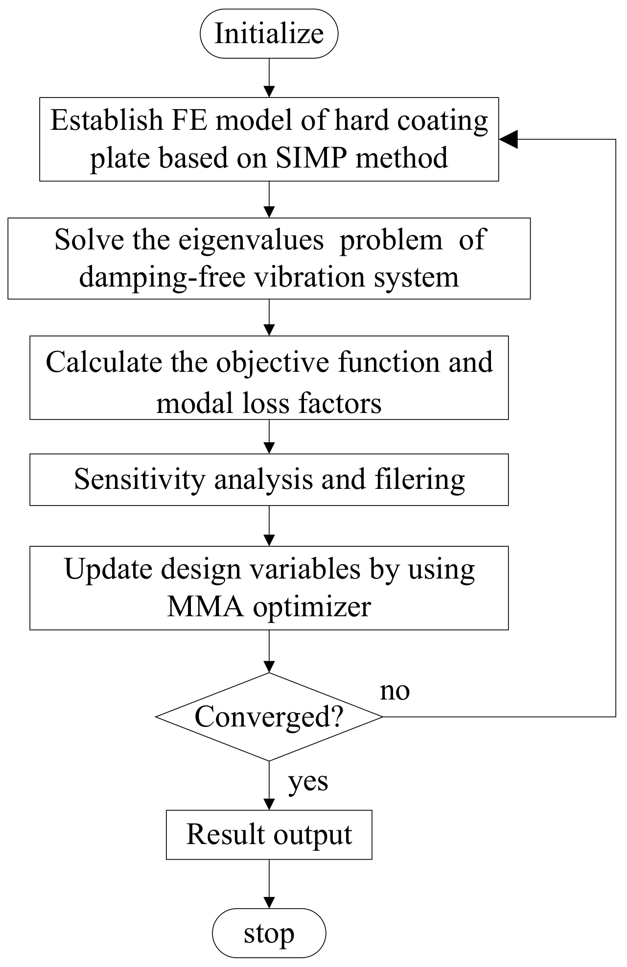
The optimization process is shown in Figure 3. The specific steps are as follows:
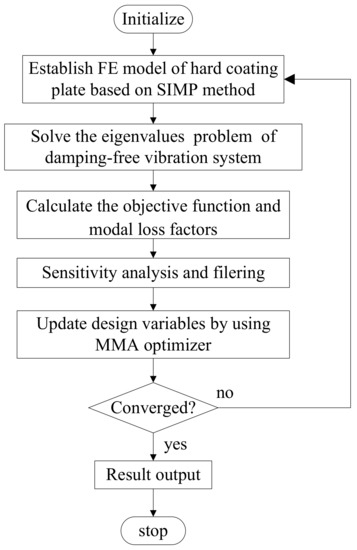
Figure 3.
Block diagram of the optimization procedure.
- Define volume constraint fraction, initialize design variables and set the corresponding parameters.
- Reassemble the mass matrix and stiffness matrix of the hard coating structure according to the value of design variables and SIMP material interpolation model.
- Carry out the modal analysis of the hard coating structure and calculate the objective function value.
- Analysis and filter the sensitivities of objective function to prevent checkerboard patterns in the design.
- Update the design variables using the MMA algorithm.
- Check whether the result converges, and if so, end the iteration. If it does not converge, the iteration is repeated.
- Output design variables and object values and display the topological distribution geometry of hard coating materials.
4. Numerical Verification
4.1. Modal Strain Energy Distribution
According to the optimization procedure shown in Figure 2, this section adopts single objective optimization method and multi-objective optimization method respectively to optimize the topology of the hard coated composite plate partially covered with hard coated damping material. In order to study the relationship between the modal strain energy and the distribution of damping materials, the modal strain energy distribution of the first six orders of base metal plate is calculated.
The geometric and material parameters of base plate and hard coating are shown in Table 1. One side of the cantilever plate is coated with Mg-Al hard coating. Among them, Young’s modulus of Mg−Al hard coating was studied by vibration beam method, and the material parameters of titanium plate were obtained from metal materials manual. For the considered cantilever thin plate, the values of the first six natural frequencies are gotten by the modal analysis program based on the proposed finite element dynamic mode and the relevant results are listed in Table 2. The corresponding modal strain energy distribution for each order is shown in Figure 4 and the 3840 elements are disposed in a 48 × 80 matrix in the figure.

Table 1.
The Geometry and Material Parameters of Substrate and Hard Coating.
Table 2.
The First Six Natural Frequencies of Thin Plate Structure.
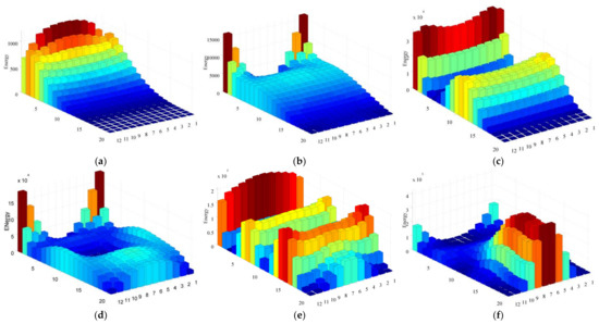
Figure 4.
The modal strain energy distribution of the first six orders of cantilever thin plate: (a) The first order; (b) the second order; (c) the third order; (d) the fourth order; (e) the fifth order; (f) the sixth order.
The first, second and third modes are bending modes, and the second, fourth and sixth modes are torsion modes. There are no repeated eigenvalues or similar complex eigenvalues. The characteristic mode corresponding to the characteristic frequency is unique, which indicates that the sensitivity analysis method of formula 24 is effective for the structure.
4.2. Damping Optimization for a Single Mode
In order to verify the correctness of the proposed method, the relationship between the distribution of coating damping material and the distribution of modal strain energy of base course is studied with a single modal loss factor as the optimization design objective. The volume percentage of coating damping material after optimization is set to 50%. Before the optimization iteration, all design variables are initialized to 0.5, and the lower bound of design variables is set to 0.001. In order to avoid matrix singularity in the optimization process. The material parameters of substrate and hard coating are shown in Table 1. In order to ensure the stability of the optimization process and the accuracy of the optimization results, the design domain is discretized by 80 × 48 4-node rectangular finite elements.
Figure 5a–f shows the topology optimization results of the hard coating damping material for the first six modes of the hard coating cantilever plate with the maximum modal loss factor as the optimization design objective under the given volume percentage constraint. It can be seen that the distribution of damping layer material is consistent with the modal strain energy of base metal plate. It also shows that the hard coating damping material can absorb the vibration energy better in the area with high modal strain energy, so as to achieve the effect of vibration suppression. Table 3 shows the modal loss factors of the full covered plate and the modal loss factors of the corresponding order after optimizing the partially covered plate with the modal loss factors of each order as the optimization design objective. Taking the first-order modal loss factor and the second-order modal loss factor as the optimization design objectives, the optimization results are compared with the full coverage method, the reduction of modal loss factor is less than 10% the modal loss factor of the other four optimization results is less than 20% lower than that of full coverage.
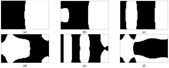
Figure 5.
Topology optimization of the cantilever hard coating thin plate for single mode: (a) The first order; (b) the second order; (c) the third order; (d) the fourth order; (e) the fifth order; (f) the sixth order.
Table 3.
The Modal Loss Factors of the Full Covered Plate and the Optimized Partially Covered Plate.
4.3. Damping Optimization for a Multiple Mode
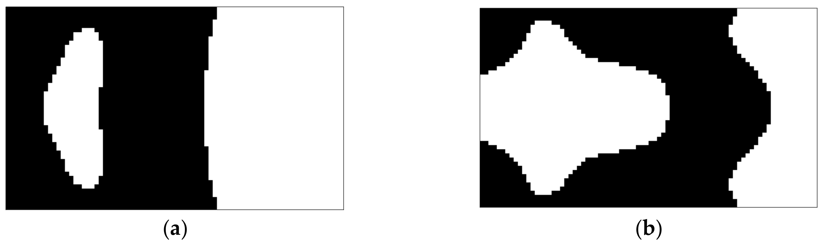
This case study focuses on topology optimization of hard-coating thin plate for multiple eigenmode, so as to achieve vibration suppression within a certain frequency bandwidth. The cantilever plate is still used for research. The geometric parameters, material properties and finite element mesh density of the structure are the same as those in the previous single objective optimization. For convenience, only the first four modes are of interest. The volume fraction ratio of the hard coating layer is restricted by α = 0.5. The first 40 eigenmodes are involved in the computation (i.e., N = 40).
It can be seen that the distribution trend of hard coating damping material can not be obtained according to the distribution of substrate modal strain energy when optimizing multiple modes at the same time. Moreover, the optimization results of multi-mode and single mode are also different.
Figure 6a shows the topology optimization results for the first three modes, with weight coefficients of 0.2, 0.5 and 0.3 respectively. Figure 5b shows the topology optimization results for the second, third and fourth modes, with weight coefficients of 0.4, 0.1 and 0.5 respectively. It can be seen that the distribution trend of hard coating damping material can not be obtained according to the distribution of substrate modal strain energy when optimizing multiple modes at the same time. Moreover, the optimization results of multi-mode and single mode are also different. The distribution of the hard coating damping material is the result of the joint action of the modal strain energy and the weight coefficient.

Figure 6.
Topology optimization of the cantilever hard coating thin plate for multiple mode: (a) Optimization for the 1st, 2nd, and 3rd mode; (b) Optimization for the 2nd, 3rd, and 4th mode.
5. Experimental Verification
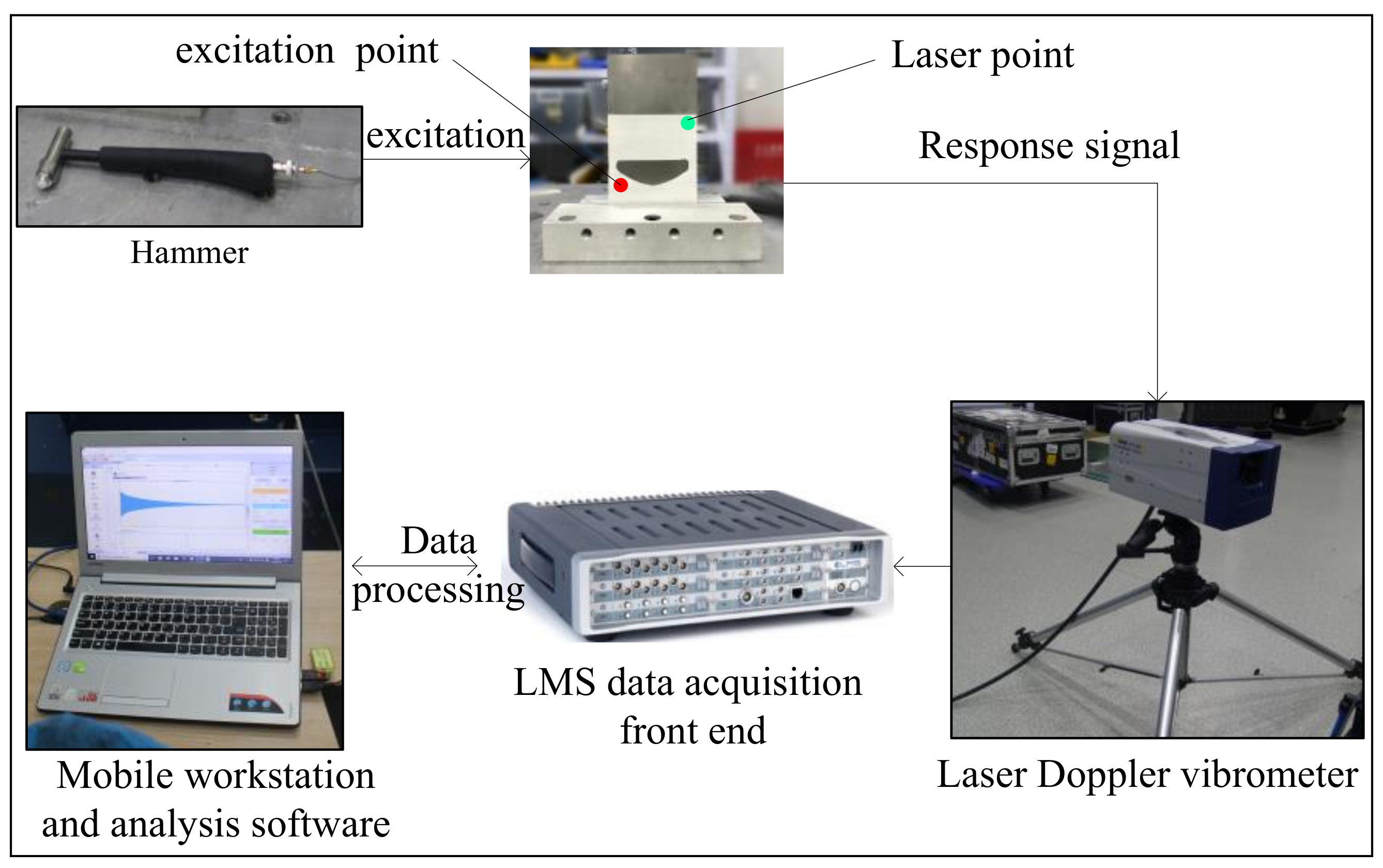
In order to verify the correctness of the topology optimization model and algorithm, two kinds of multi-objective optimization results were taken as examples, and the hard coating composite plate specimens were fabricated by plasma spraying. The vibration test platform and test principle are shown in Figure 7. The vibration test system includes hammer, laser Doppler vibration meter, LMS data acquisition front end, mobile workstation, fixture, vibration table and modal analysis software. The experimental process is as follows:

Figure 7.
Schematic of vibration test system of the CLD treated plate.
- the hard coated cantilever plate is fixed on the shaking table with a fixture
- the excitation signal is generated by hammering the surface of the composite plate
- the vibration acceleration response of the composite plate is measured with a laser vibrometer
- the response signal collected by the LMS data acquisition mobile front end is transmitted to the mobile workstation, and the analysis software processes the response signal and outputs the results.
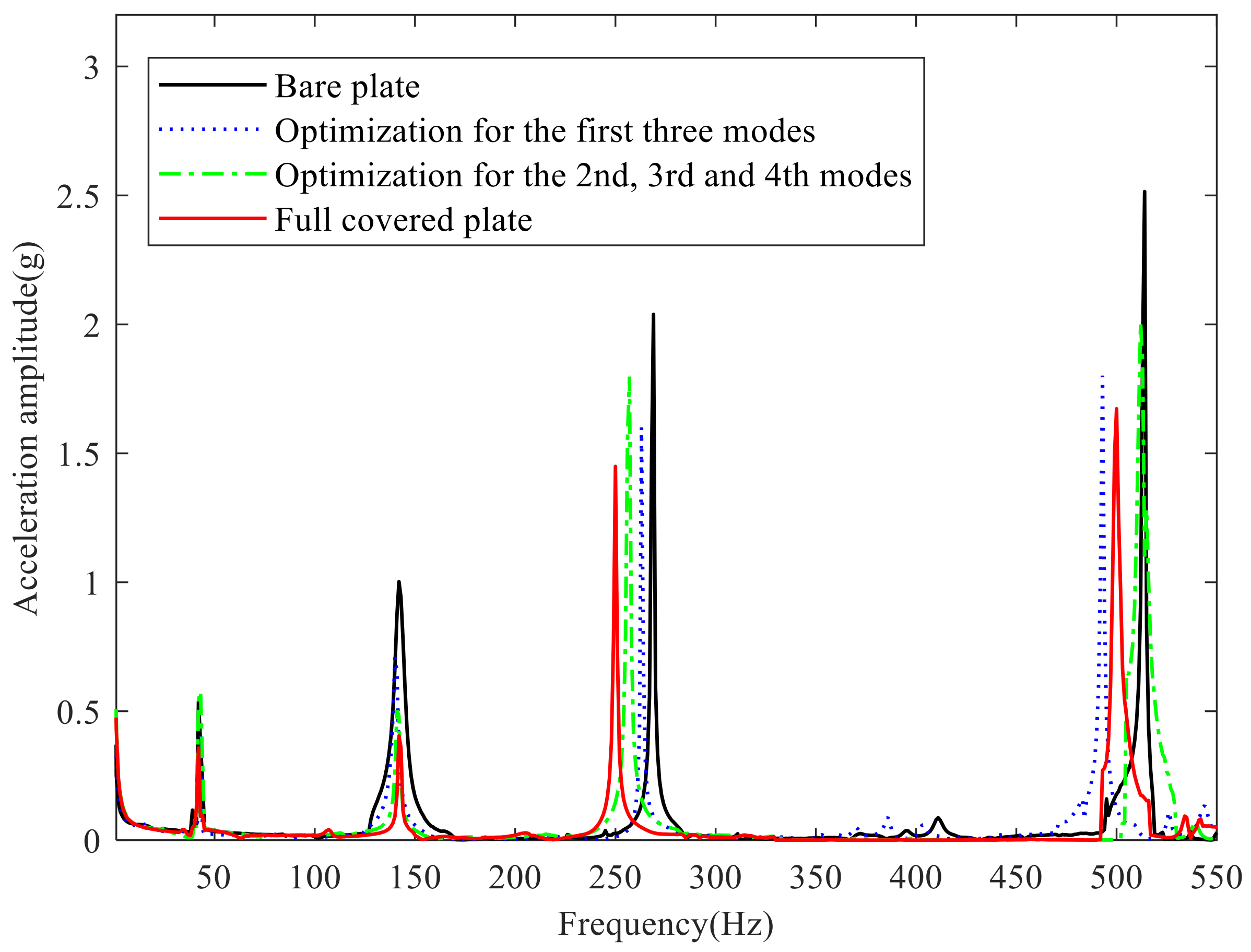
In this paper, the full coverage hard coated plate, bare plate and the above two kinds of multi-objective optimization of local coverage hard coated plate are studied. The positions of the excitation input point and the response output point of the four plates are consistent. Figure 8 shows the experimental results of the acceleration frequency response. It can be seen that compared with the smooth plate, the composite plate covered with damping hard coating has smaller resonance response amplitude. The larger the weight coefficient is, the more obvious the suppression of resonance response amplitude is. This proves the correctness of the proposed method. At the same time, the optimization of the first three modes also has a certain vibration suppression effect on the resonance response amplitude at the fourth-order modal frequency, which is mainly because the damping material is also distributed in the higher position of the fourth-order modal strain energy.
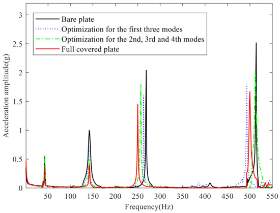
Figure 8.
Acceleration amplitude versus frequency at the laser point of the composite cantilever plate.
6. Conclusions
Based on the energy method, the dynamic model of partially covered hard coating thin plate is established. Based on the SIMP method, the relationship between the stiffness matrix, mass matrix and the relative density of the element is obtained. Based on the simplified sensitivity calculation method, the sensitivity of the objective function is analyzed. The gradient based MMA optimization algorithm is used to update the design variables. Numerical examples and experimental results show that:
- Through the topology optimization results of multi single mode, it can be seen that the hard coating damping materials are mainly distributed in the region with high modal strain energy, which is consistent with the traditional empirical method. Compared with full coverage, local coverage can not only effectively suppress vibration, but also save materials. And, the less the coating material, the smaller the change of the matrix structure itself.
- The topology optimization of hard coated thin plate with multiple mode loss factors can effectively suppress the vibration in a certain frequency band. In practical engineering, the vibration environment of the thin walled structure is often the combined action of various vibration loads in a certain frequency band, which shows that the method proposed in this paper has practical significance.
- The objective function converges to the optimal value stably, the optimization result is clear, there is no checkerboard phenomenon, and it is easy to reconstruct and process. The experimental results are consistent with the simulation results. The above results show that the method is effective and practical.
- The experimental results show that the proposed topology optimization design method can effectively suppress the vibration in a certain frequency band, which proves the correctness of the proposed method.
Author Contributions
H.L. and R.C. carried out the modeling and wrote the paper, H.L. and S.G. analyzed the calculation results, R.C. and J.F. carried out the simulation and experiment of the work. All authors have read and agreed to the published version of the manuscript.
Funding
This research was funded by National Natural Science Foundation of China, grant number 51975567, Liao Ning Revitalization Talents Program, grant number XLYC1907152, Natural Science Foundation of Liaoning Province Natural Science Foundation of Liaoning Province, grant number 2019MS347, Autonomous Fund Project of the State Key Laboratory of Robotics, grant number E129030201, Youth Innovation Promotion Association, grant number 2018237, and Jiang Xin-song Innovation Fund, grant number 20180504.
Institutional Review Board Statement
Not applicable.
Informed Consent Statement
Not applicable.
Data Availability Statement
Data is contained within the article.
Acknowledgments
Special thanks are due to K. Svanberg of the Royal Institute of Technology in Stockholm for supplying the Method of Moving Asymptotes code.
Conflicts of Interest
The authors declare no conflict of interest.
References
- Ivancic, F.; Palazotto, A. Experimental considerations for determining the damping coefficients of hard coatings. J. Aerosp. Eng. 2005, 18, 8–17. [Google Scholar] [CrossRef]
- Gregori, G.; Lì, L.; Nychka, J.A.; Clarke, D.R. Vibration damping of superalloys and thermal barrier coatings at high-temperatures. Mat. Sci. Eng. A Struct. 2007, 466, 256–264. [Google Scholar] [CrossRef]
- Casadei, B.K.; Clarke, D.R. Finite element study of multi-modal vibration damping for thermal barrier coating applications. Comp. Mater. Sci. 2013, 79, 908–917. [Google Scholar] [CrossRef]
- Sun, W.; Li, H.; Han, Q.K. Identification of mechanical parameters of hard-coating materials with strain-dependence. J. Mech. Sci. Technol. 2014, 28, 81–92. [Google Scholar] [CrossRef]
- Wei, S.; Liu, X.; Jiang, J. Vibration analysis of hard-coating laminated plate considering strain-dependent characteristic. J. Low Freq. Noise Vib. Act. Control 2018, 37, 1–12. [Google Scholar]
- Sun, W.; Liu, R.; Fan, Y. Analytical modeling and damping optimization for a thin plate partially covered with hard coating. Arch. Appl. Mech. 2018, 88, 897–912. [Google Scholar] [CrossRef]
- Wei, S.; Rong, L. Damping optimization of hard-coating thin plate by the modified modal strain energy method. Coatings 2017, 7, 32. [Google Scholar]
- Ansari, M.; Shoja-Razavi, R.; Barekat, M.; Man, H.C. High-temperature oxidation behavior of laser-aided additively manufactured NiCrAlY coating. Corros. Sci. 2017, 118, 168–177. [Google Scholar] [CrossRef]
- Feng, G.; Wei, S. Vibration characteristics and damping analysis of the blisk-deposited hard coating using the Rayleigh-Ritz method. Coatings 2017, 7, 108. [Google Scholar]
- Li, H.; Sun, W.; Zhu, M.; Xue, P. Experimental study on the influence on vibration characteristics of thin cylindrical shell with hard coating under cantilever boundary condition. Shock. Vib. 2017, 2017, 1–23. [Google Scholar] [CrossRef]
- Du, G.; Tan, Z.; Li, G.; Ba, D.; Liu, K. Damping properties of arc ion plating NiCrAlY coating with vacuum annealing. Coatings 2018, 8, 20. [Google Scholar] [CrossRef] [Green Version]
- Li, H.; Zhou, Z.; Sun, H.; Sun, W.; Wen, B. Theoretical study on the influence of hard coating on vibration characteristics of fiber-reinforced composite thin shell. Coatings 2018, 8, 87. [Google Scholar] [CrossRef] [Green Version]
- Stefano, A.; Giuseppe, C.; Angelo, C. Experimental evaluation and modeling of the damping properties of multi-layer coated composites. Coatings 2018, 8, 53. [Google Scholar]
- Tassini, N.; Patsias, S.; Lambrinou, K. Ceramic coatings: A phenomenological modeling for damping behavior related to microstructural features. Mat. Sci. Eng. A Struct. 2006, 442, 509–513. [Google Scholar] [CrossRef]
- Torvik, P.J. A Slip Damping model for plasma sprayed ceramics. J. Appl. Mech. 2009, 76, 1089–1094. [Google Scholar] [CrossRef]
- Al-Rub, R.; Palazotto, A.N. Micromechanical theoretical and computational modeling of energy dissipation due to nonlinear vibration of hard ceramic coatings with microstructural recursive faults. Int. J. Solids. Struct. 2010, 47, 2131–2142. [Google Scholar] [CrossRef] [Green Version]
- Yang, Z.X.; Han, Q.K.; Jin, Z.H.; Qu, T. Solution of natural characteristics of a hard-coating plate based on Lindstedt–Poincaré perturbation method and its valedictions by FEM and measurement. Nonlinear Dynam. 2015, 81, 1207–1218. [Google Scholar] [CrossRef]
- Hui, L.; Liu, Y.; Wei, S. Analysis of nonlinear vibration of hard coating thin plate by finite element iteration method. Shock. Vib. 2014, 2014, 941709. [Google Scholar]
- Chen, Y.; Zhai, J.; Han, Q. Vibration and damping analysis of the bladed disk with damping hard coating on blades. Aerosp. Sci. Technol. 2016, 58, 248–257. [Google Scholar] [CrossRef]
- Lumsdaine, A. Topology optimization of constrained damping layer treatments. In Proceedings of the ASME International Mechanical Engineering Congress and Exposition, New Orleans, LA, USA, 17–22 November 2002; Volume 36258, pp. 149–156. [Google Scholar]
- Lumsdaine, A.; Pai, R. Design of constrained layer damping topologies. In Proceedings of the ASME International Mechanical Engineering Congress and Exposition, Washington, DC, USA, 15–21 November 2003; Volume 37076, pp. 219–227. [Google Scholar]
- Chen, Y.C.; Huang, S.C. An optimal placement of CLD treatment for vibration suppression of plates. Int. J. Mech. Sci. 2002, 44, 1801–1821. [Google Scholar] [CrossRef]
- Hou, S.W.; Jiao, Y.H.; Chen, Z.B. Optimum layout of passive constrained layer damping treatment using genetic algorithms. In Proceedings of the ASME International Mechanical Engineering Congress and Exposition, Vancouver, BC, Canada, 12–18 November 2010; Volume 44502, pp. 371–376. [Google Scholar]
- Zheng, H.; Cai, C.; Pau, G.S.H.; Liu, G.R. Minimizing vibration response of cylindrical shells through layout optimization of passive constrained layer damping treatments. J. Sound. Vib. 2005, 279, 739–756. [Google Scholar] [CrossRef]
- Andreassen, E.; Clausen, A.; Schevenels, M.; Lazarov, B.S.; Sigmund, O. Efficient topology optimization in MATLAB using 88 lines of code. Struct. Multidiscip. Optim. 2011, 43, 1–16. [Google Scholar] [CrossRef] [Green Version]
- Sigmund, O. On the usefulness of non-gradient approaches in topology optimization. Struct. Multidiscip. Optim. 2011, 43, 589–596. [Google Scholar] [CrossRef]
- Ling, Z.; Ronglu, X.; Yi, W.; El-Sabbagh, A. Topology optimization of constrained layer damping on plates using Method of Moving Asymptote (MMA) approach. Shock Vib. 2011, 18, 221–244. [Google Scholar] [CrossRef]
- Fang, Z.P.; Zheng, L. Topology optimization for minimizing the resonant response of plates with constrained layer damping treatment. Shock. Vib. 2015, 2015, 376854. [Google Scholar] [CrossRef]
- Zheng, W.; Lei, Y.; Li, S.; Huang, Q. Topology optimization of passive constrained layer damping with partial coverage on plate. Shock. Vib. 2013, 20, 199–211. [Google Scholar] [CrossRef]
- Nazir, A.; Jeng, J.Y. A high-speed additive manufacturing approach for achieving high printing speed and accuracy. J. Mech. Eng. Sci. 2019, 234, 1–9. [Google Scholar] [CrossRef]
- Svanberg, K. The method of moving asymptotes—A new method for structural optimization. Int. J. Numer. Meth. Eng. 1987, 24, 359–373. [Google Scholar] [CrossRef]
- Sigmund, O. Morphology-based black and white filters for topology optimization. Struct. Multidiscip. Optim. 2007, 33, 401–424. [Google Scholar] [CrossRef] [Green Version]


Publisher’s Note: MDPI stays neutral with regard to jurisdictional claims in published maps and institutional affiliations. |
© 2021 by the authors. Licensee MDPI, Basel, Switzerland. This article is an open access article distributed under the terms and conditions of the Creative Commons Attribution (CC BY) license (https://creativecommons.org/licenses/by/4.0/).