Article

Effects of Input Power Ratio of AlCr/Ti Target on the Microstructural and Mechanical Properties of AlTiCrN Coatings Synthesized by a High-Power Impulse Magnetron Sputtering Process

1
Bachelor Program in Interdisciplinary Studies, National Yunlin University of Science and Technology, Douliu 64002, Taiwan
2
Department of Materials Engineering, Ming Chi University of Technology, New Taipei 24301, Taiwan
3
Center for Plasma and Thin Film Technologies, Ming Chi University of Technology, New Taipei 24301, Taiwan
*
Author to whom correspondence should be addressed.
Coatings 2021, 11(7), 826; https://doi.org/10.3390/coatings11070826
Submission received: 16 June 2021 / Revised: 3 July 2021 / Accepted: 6 July 2021 / Published: 9 July 2021

Abstract

:
In this study, five AlTiCrN nitride coatings were deposited via high-power impulse magnetron sputtering (HiPIMS). The AlTiCrN coatings were synthesized with high contents of Al or Ti and a lower fraction of Cr, using Ti and Al70Cr30 targets with five different input power ratios. Electron probe microanalyzer results revealed that the increased rate of Ti contents in the coatings can be divided into two regions due to the difference of power densities for HiPIMS (>0.5 kW/cm2) and modulated pulsed power (MPP) (<0.5 kW/cm2). The deposition rate and thickness of the coatings depended on the sputtering yield of two metal targets under HiPIMS and MPP modes. The grain size of the coatings decreased from 60 to 40 nm as the input power ratios of the AlCr/Ti targets decreased due to their lower thickness values and lower Al content. Selected area electron diffraction patterns and X-ray diffraction results revealed that the TiN and AlTiN phases can be found in the coating containing higher Ti content, whereas the AlN, CrN, and AlCrN phases were observed in the coating with a higher Al concentration. Nevertheless, decreasing the concentration of Ti had a detrimental effect on the mechanical properties of AlTiCrN coatings, due to a promotion in grain size and the formation of AlN, which is softer than TiN. It is noticed that our results differed from those in previous reports, in which a grain refinement effect was observed due to increasing Al content. In this work, the effect of processing the parameters of the HiPIMS and MPP power systems on the grain size and the mechanical property of the coating was also discussed.

1. Introduction

High-quality cutting tools, such as micro drills, are crucial to the manufacturing of printed circuit boards (PCBs). Protective coatings are the most effective approach for enhancing the performance and service life of these tools. Over the past 20 years, the market share of coated cutting tools has risen from 68% to 85%. Binary nitride coatings of CrN and TiN have been widely used to improve the service life of cutting tools, due to their high strength and resistance to wear and corrosion [1,2,3]. TiN coatings begin to oxidize at 500 °C, whereas CrN coatings oxidize at 600 °C [4]. This is an important concern due to the high temperatures encountered in high-speed cutting. Researchers have sought to enhance the oxidation resistance of binary nitride coatings by introducing higher quantities of Al (up to 50 at.%), resulting in a thin film of Al2O3 formed on the surface. The resulting CrAlN and TiAlN films provided even higher hardness and thermal stability with an oxidation resistance of up to 1000 °C [5,6]. The increased hardness associated with the introduction of Al can be attributed to the B1 structure of the metastable AlxCr1−xN solid solution and nano-scale domains [7]. Note that AlCrN and AlTiN systems represent metastable solid solutions, which maintain an FCC structure with an Al content of up to 70 at.% within the metal sublattice.
Zhu et al. [8] reported that the hardness of TiAlN films (36 GPa) exceeded that of AlCrN (32 GPa); however, the wear rate of TiAlN (10 × 10−6 mm3/Nm) was higher than that of AlCrN (5 × 10⁻⁶ mm3/Nm). Fox-Rabinovich et al. [9] reported that the hardness of TiAlN (30 GPa) film was higher than that of AlCrN (24.7 GPa). In fatigue testing, the TiAlN fractured violently, whereas the AlCrN coating presented only small cracks. In a milling test, the final depth of the TiAlN-coated tool (1.91 μm) exceeded that of the AlCrN-coated tool (1.66 μm). Durmaz and coworkers [10] discovered that the surface roughness of work pieces milled using TiAlN-coated carbide cutting tools was lower than that of surfaces milled using AlCrN-coated tools. Discrepancies in previous studies show the need to delve into the impact of element ratio parameters on the final coating properties.
Binary and ternary transition-metal, nitride-based coatings can be created using a variety of physical vapor deposition (PVD) techniques, such as direct current magnetron sputtering (DCMS) [11], cathodic arc ion plating [12], high-power impulse magnetron sputtering (HiPIMS) [13], and arc-sputter hybrid processes [14]. HiPIMS has attracted particular attention due to the excellent density and smoothness of the resulting coatings, which are superior to those produced using conventional PVD technologies. For example, Samuelsson and coworkers [15] found that the density of thin films created via HiPIMS is higher than that of films produced using conventional PVD. The higher hardness values of CrN [16,17] and TiN [17] coatings grown by HiPIMS were achieved, as compared with those deposited by traditional DCMS methods.
Researchers have also developed coatings with compositions of greater complexity (e.g., ternary, quaternary, and quinary compounds), which exhibit superior mechanical properties. Polcar et al. [16] and Fox–Rabinovich et al. [17] analyzed the effects of the tribological performance of AlCrTiN coatings with high Al contents at both high and room temperature. Tam et al. [18] analyzed the effects of Ti and Al contents on the structure, mechanical properties, and tribological performance of CrTiAlN coatings. Fernandes et al. [19] analyzed the tribological performance of TiAlCrN coatings with different Cr contents. As discussed above, the effect of single- or two-metal content in quaternary compound coating was reported. However, various metal contents under HiPIMS and MPP modes lack discussion. In this work, we investigated the influence of input power ratio of the AlCr/Ti target on the microstructure, composition, hardness, and adhesive strength of AlTiCrN coatings prepared via HiPIMS and using targets of Ti and Al70Cr30. The formation mechanisms, microstructure, and mechanical properties of the coatings are also discussed.

2. Experimental Details

The HiPIMS system used in this work was illustrated in detail in our previous study [20]. AlTiCrN coatings were deposited on P-type (100) Si, AISI 304 stainless steel, and high-speed steel (HSS, SKH9; radius = 14.5 mm; thickness = 8 mm) disk substrates using the HiPIMS technique. The coatings deposited on the HSS substrate were used for mechanical analysis. The coatings grown on Si wafers were employed for material analysis (EPMA, SEM, and TEM). The coatings fabricated on AISI 304 stainless steel substrates were used for XRD analysis.
A schematic diagram of the experimental apparatus is shown in Figure 1. The rectangular Ti and Al70Cr30 targets (99.9%), with a size of 45.3 cm × 17.3 cm and target areas of 783.7 cm2, were connected to a HiPIMS power supply in bipolar output mode with the following parameters: an on-time of 150 μs within 5000 μs and a duty cycle of 3%. A DC power supply (20 kW, Hüttinger 4020, TRUMPF, Ditzingen, Germany) was used for substrate biasing. The rotating speed of the substrate holder was 4.5 rpm. No substrate heating was used during deposition. Detailed deposition parameters are listed in Table 1.
The stainless steel and HSS substrates were cleaned in an automated cleaning line comprising of a series of alkali solutions and de-ionized water baths, followed by a drying furnace. The Si wafers were cleaned by following the procedures of RCA (Radio Corporation of America) cleaning. The base pressure prior to the experiment was 6.6 × 10⁻⁴ Pa. Plasma etching was conducted via Ar glow discharge with a DC bias of −800 V and at a working pressure of 0.5 Pa. Metal ion bombardment was then conducted via HiPIMS with a gradual reduction in DC bias from −800 to −600, and then to −400 and −200 V in intervals of 5 min.
During interlayer deposition, the Ar flow rate was reduced to 50 sccm and kept constant during the subsequent deposition. First, the output of power applied to the dual Ti targets was 5 kW in bipolar mode. An interlayer of pure Ti was deposited at a DC bias of −120 V over a period of 10 min under a working pressure of 0.5 Pa. Then, a TiN interlayer was deposited by introducing N2 gas at a flow rate of 9 sccm and a working pressure of 0.5 Pa under a DC bias of −60 V.
For the 130 min deposition of the AlTiCrN coatings, the bias voltage was reduced to −45 V to attract the bombardment of positive ions, while the power ratios of Al70Cr30 to Ti targets were varied from 0.25 to 4, for the deposition of five coatings under a working pressure of 0.53 Pa.
The morphology of the coatings was evaluated via field emission scanning electron microscopy (FE-SEM, S8000, Hitachi, Tokyo, Japan). The SEM image was obtained via a single secondary electron detector. The coatings on the Si substrates were cut in halves for FE-SEM cross-sectional analysis. Transmission electron microscopy (TEM) images and selected area electron diffraction (SAED) were observed via a TEM (JEOL, JEM-2100 LaB6, Tokyo, Japan). The TEM was operated at an accelerating voltage of 200 kV. The TEM samples were obtained using a focused ion beam (FIB) technique. A grazing incidence X-ray diffractometer (GIXRD, PANalytical, X’pert, Almelo, The Netherlands) with an incidence angle of 1.5° and a Cu Kα radiation was adopted to analyze the phase structures of the coatings. A field-emission electron probe microanalyzer (FE-EPMA, JEOL, JXA-8500F, Japan) was employed to analyze the chemical compositions of the coatings. Quantitative analysis was also carried out using wavelength-dispersive spectroscopy (WDS) on an EPMA.
The hardness and Young’s modulus of the coatings were measured using a nanoindentation instrument (TI-900, TriboIndenter, Hysitron, Minneapolis, MN, USA) with a Berkovich diamond probe tip. The loading rate was 1000 μN/s and the maximum indentation depth of 70–100 nm was controlled to minimize the influence of the substrate on the hardness measurements. Each coating was measured seven times and the mean hardness was derived from the five values that remained after removing the highest and lowest values.

3. Results and Discussion

The current-voltage characteristics of the Ti and AlCr targets under five different input power ratios at a fixed duty cycle of 3% and a frequency of 200 Hz for HiPIMS process are listed in Table 2. This result indicates that the peak power density increases when increased input power is supplied to the target. Gudmundsson et al. [21] observed that the HiPIMS discharge operates with peak power densities in the range of 0.5–10 kW/cm2, repetition frequencies in the range of 50–5000 Hz, and duty cycles in the range of 0.5%–5%. In this study, the peak power density of Ti or AlCr target was lower than the standard value, >0.5 kW/cm2, of HiPIMS when the input power of Ti or AlCr target was lower than 0.75 kW. This range of peak power density belongs to the medium power density (from 0.05 to 0.5 kW/cm2) of modulated pulsed power (MPP). However, as the input power is over 1.25 kW, the peak power density is higher than 0.5 kW/cm2, implying the requirement of HiPIMS discharge is achieved.
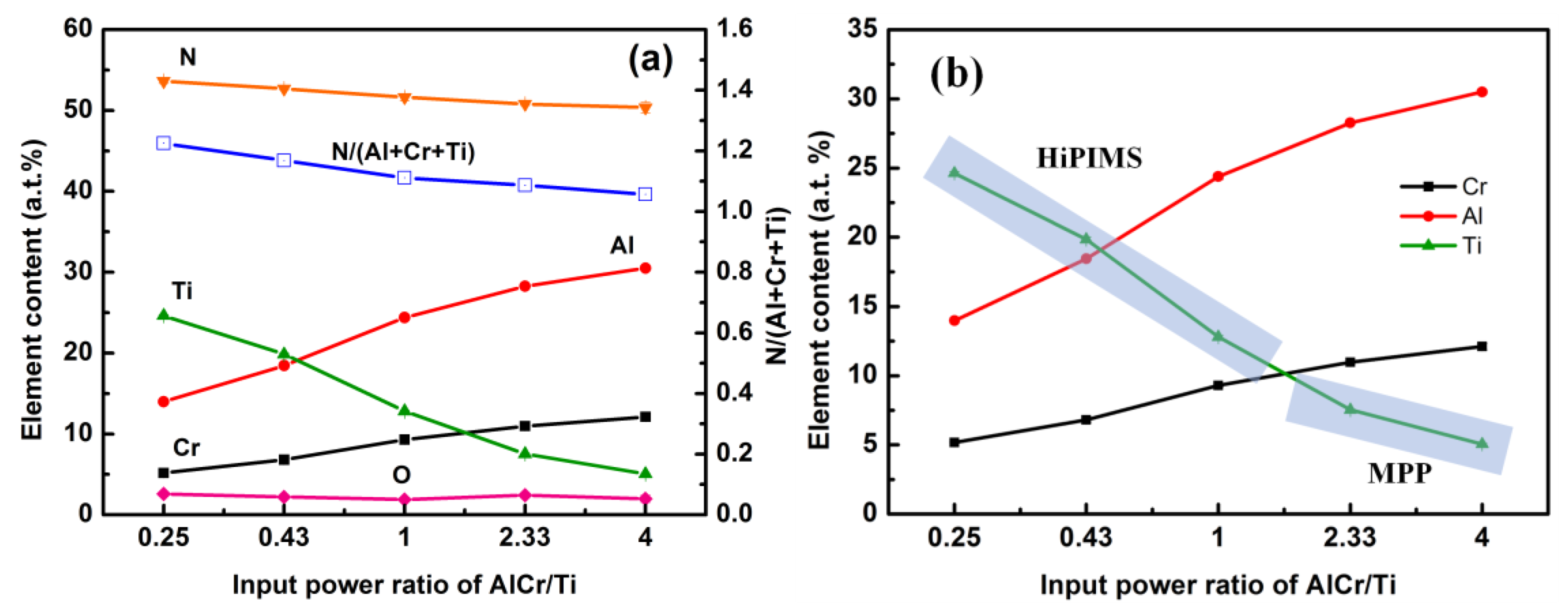
Figure 2a shows the chemical compositions of all elements in five AlTiCrN coatings deposited under five different input power ratios. The Al and Cr contents in the coatings increased with the input power ratio of AlCr/Ti. Overall, the content of Al is higher than Cr and the ratio of Al to Cr is approximatively 3:1. However, the Al content does not increase linearly with the increase of the target power. We suggest that the lightweight Al atoms and ions in the plasma are more susceptible to collision with other, heavier atoms and ions, leading to a decreasing number of Al atoms and ions toward the substrate. The concentration of Ti also decreases with the decreasing cathode power of the Ti target. In general, the input power of the cathode determines the kinetic energy of incident ions striking on the target; therefore, the number of sputtered atoms are proportional to the cathode power [22]. Note that the increased rate of Ti content in the coating can be divided into two regions, as shown in Figure 2b. A higher content of the Ti element can be seen in the HiPIMS range. This can be attributed primarily to the difference in power densities between HiPIMS and MPP, in which the higher ionization of the sputtered atoms was produced during the HiPIMS process [21]. The N/(Cr + Al + Ti) ratios are all higher than 1 in five coatings, regardless of the input power ratio, implying that the nitrogen content was sufficient to form a stoichiometric AlTiCrN coating similar to a binary nitride coating. Note that the oxygen content in each coating is less than 2.5 at.%.
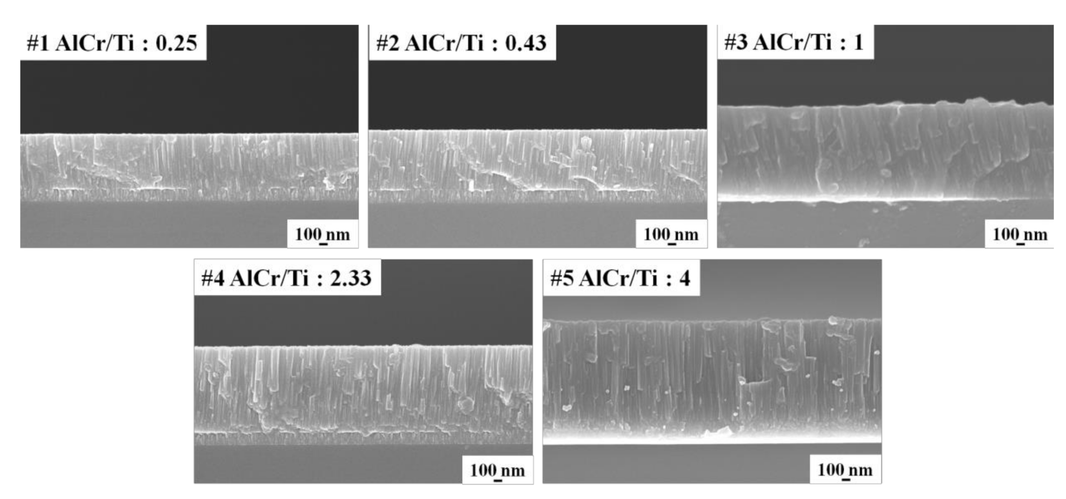
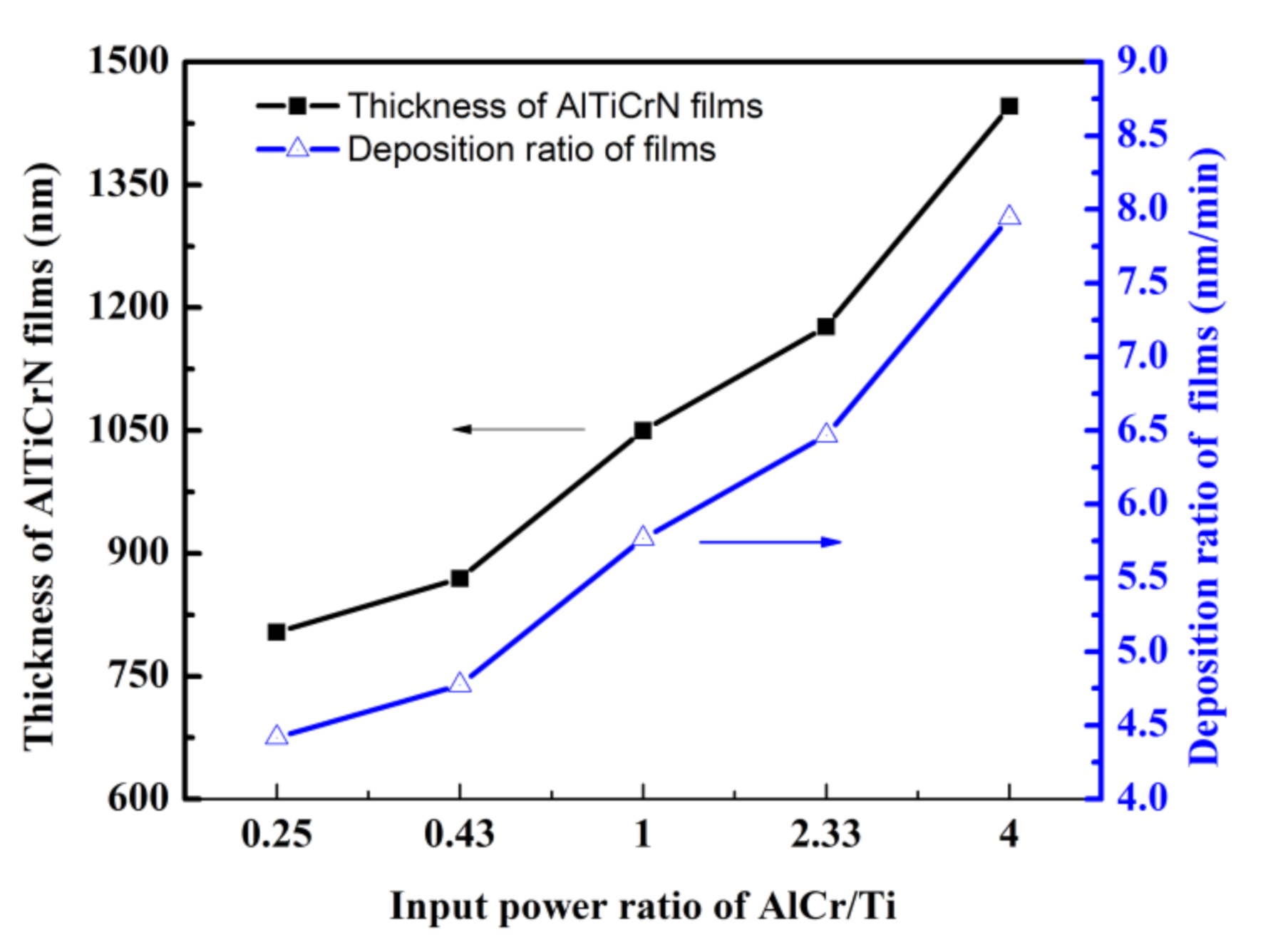
Figure 3 presents the top-view FE-SEM images of AlTiCrN coatings deposited using five different input power ratios. The average grain size (nodular size) values of five coatings measured using FE-SEM images are 39.9 ± 0.8 nm (#1), 42.8 ± 0.9 nm (#2), 47.1 ± 0.7 nm (#3), 55.4 ± 1.5 nm (#4), and 59.3 ± 2.5 nm (#5), which shows an increasing tendency with increasing input power ratio of AlCr/Ti target. It is noticeable that the increase of grain size with increasing Al content obtained in this work is different from those reports in literature [23,24,25], in which a grain refinement effect was found due to the addition of more Al content. This phenomenon can be attributed to the composition of the quaternary nitride coatings in this study. The sizes of the surface grains increased with an increase of input power ratio due to the thickness effect. Andrievski et al. [26] revealed that the grain size increased proportionally with the thickness of the thin film, in which the size of the TiN grains was larger than that of CrN grains at a fixed film thickness. We believe that this is primarily caused by the high-energy interactions between metal ions and the substrate surface, leading to the formation of crystallization nuclei. Samuelsson et al. [15] discovered that the ionization fraction and film density of Ti is higher than those of Al due to the fact that the electron impact ionization of Al is twice as high than that of Ti and the mobility of Al+ is also slightly higher. When the input power ratio is 0.25, the peak power intensity of the Ti target reaches 705 W/cm2 and therefore fulfills the standard requirement for HiPIMS. Lewin et al. [27] reported that the intense ion-bombardment from HiPIMS discharge can cause grain refinement. It is noted that as the input power ratio is 4, the peak power intensity on the Al70Cr30 target reaches 704 W/cm2, implying that many Al metal ions are created from the Al70Cr30 target. However, the energy of the Al ions decreases due to multiple collisions in the plasma and thus shortens their lifetime. The coating thickness can be determined from the cross-sectional FE-SEM images, as shown in Figure 4. It appears that the coating thickness increases with increasing input power ratios and corresponding sputtering yields. Under the given kinetic energy conditions of 600 eV for Ar ions, the sputtering yield values of Al, Ti, and Cr are 1.2, 0.6, and 1.3, respectively [28]. The sputtering yield is positively related to the deposition rate. As depicted in Figure 5, increasing the input power ratio of the AlCr/Ti target from 0.25 to 4.0 can increase the deposition rate from 4.4 to 8.0 nm/min and the resulting thickness of the AlTiCrN coatings from 0.8 to 1.5 μm.
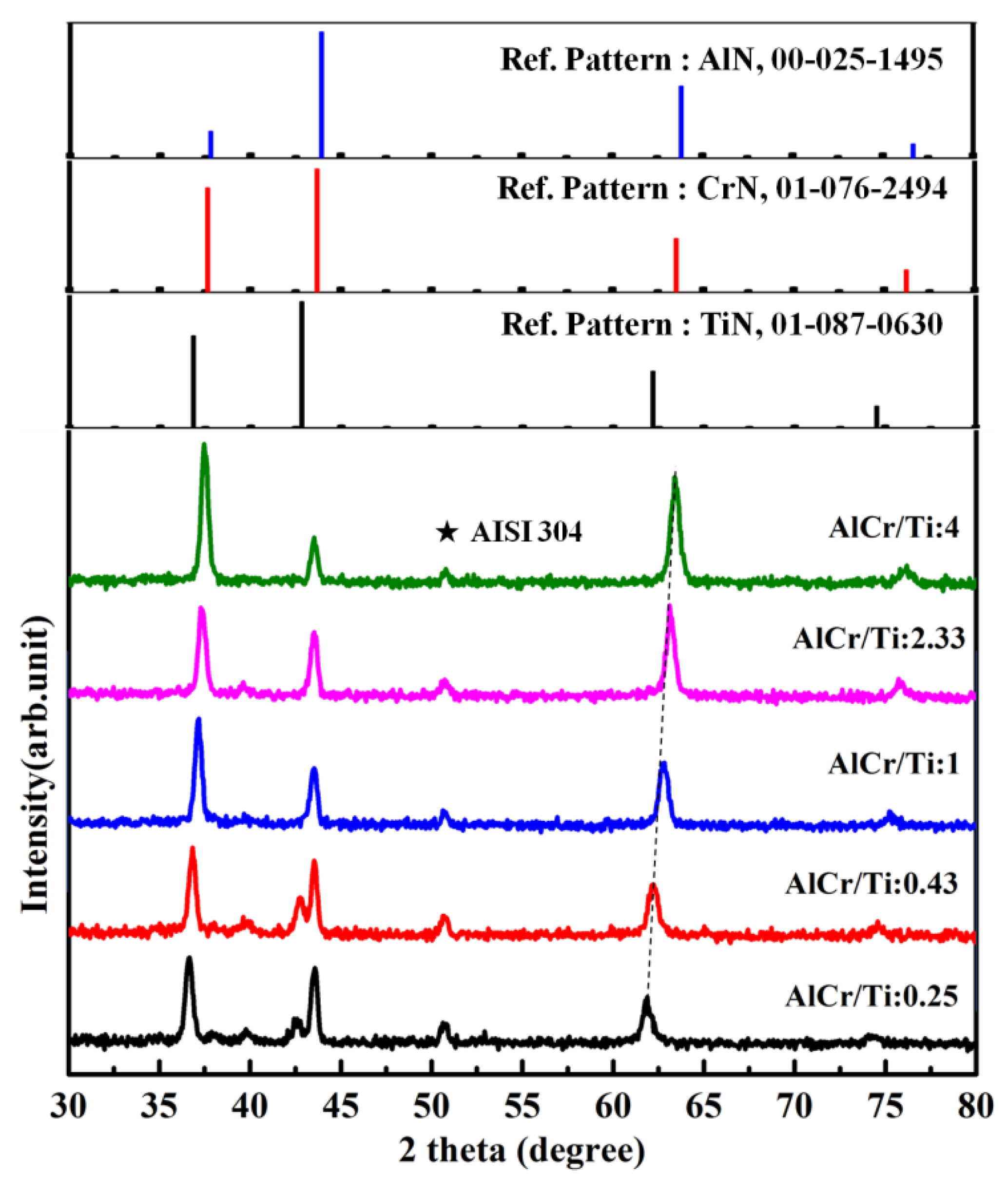
Figure 6 presents the XRD patterns of five AlTiCrN coatings, deposited using five input power ratios of the AlCr/Ti target. All of the diffraction peaks correspond to CrN, AlN, and TiN, according to JCPDS-ICDD 01-76-2494, 25-1495, and 01-87-630, respectively. Increasing the input power ratio of the AlCr/Ti target leads to a shift in these peaks to higher diffraction angles due to the decrease of lattice parameters: TiN (0.425 nm), CrN (0.414 nm), and c-AlN (0.407 nm) [29]. As the input power ratios of AlCr/Ti are 0.25 and 0.43, a peak characteristic of TiN (200) can be observed due to the higher concentrations of Ti, as compared to the other metal elements. When the input power ratio of the AlCr/Ti target exceeds 1, the main phase can be identified as (AlCr)N due to the content of Al + Cr that is higher than Ti. The (AlCr)N peaks are slightly shifted to the right when compared with CrN peaks due to the substitution of Cr atoms by Al atoms with a smaller atomic radius [30]. The crystallite sizes of the AlCrTiN coatings were also estimated from the X-ray diffraction and found to decrease slightly with decreasing Ti content, according to the Sherrer formula [31]: D = 0.9λ/(K × cosθ), where D is the crystallite size perpendicular to the plane, λ is the X-ray wavelength, K is the full-width at half-maximum in radians, and θ is the Bragg angle. It is obvious that increasing the input power ratio from 0.25 to 4 leads to the increase in crystallite size from 14.9 to 18.7 nm (as shown in Table 3).
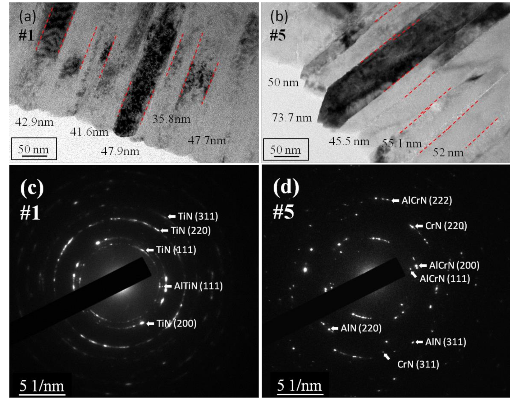
Figure 7 illustrates the TEM images and selected area electron diffraction (SAED) of the FIB lamella results, showing the microstructure of AlTiCrN coatings #1 and #5 produced using input power ratios of 0.25 and 4. The orientation of the FIB lamella is the on surface of the AlTiCrN thin film. When the input power ratio was decreased from 4 to 0.25, the average width of the columnar structure in the TEM images in Figure 7a,b decreased from 55.3 to 43.2 nm. Note that the average width value of the columnar structures is strongly related to the coating hardness. We also observed that the surface structures of the two AlTiCrN coatings changed from smooth to sharp morphology and the effect of grain refinement as the input power ratio of the AlCr/Ti target was increased from 0.25 to 4. Cheng et al. [30] and Li et al. [24] reported that films with a (110) structure present a star-shaped topography, whereas a (111) structure shows a trigonal-shaped topography. The SAED patterns in Figure 7c,d reveal spotty rings, indicating the FCC structure in the two AlTiCrN coatings. Increasing the input power ratio of the AlCr/Ti target caused a structural transformation from a TiN phase to an AlCrN phase. Figure 7d confirms that the #5 AlTiCrN coating is composed of a fcc-AlCrN solid solution, along with AlN and CrN phases. No hcp-AlN or other compound phases can be seen in Figure 7d due to the fact that the concentration of Al is below 70%, which prevents the formation of the hcp-AlN phase [32]. Note that these results are in good agreement with the GIXRD results, as depicted in Figure 6. The SAED and GIXRD results revealed that the TiN and AlTiN phases can be found in the coating containing a higher Ti content, whereas the AlN, CrN, and AlCrN phases were observed in the coating with a higher Al concentration.
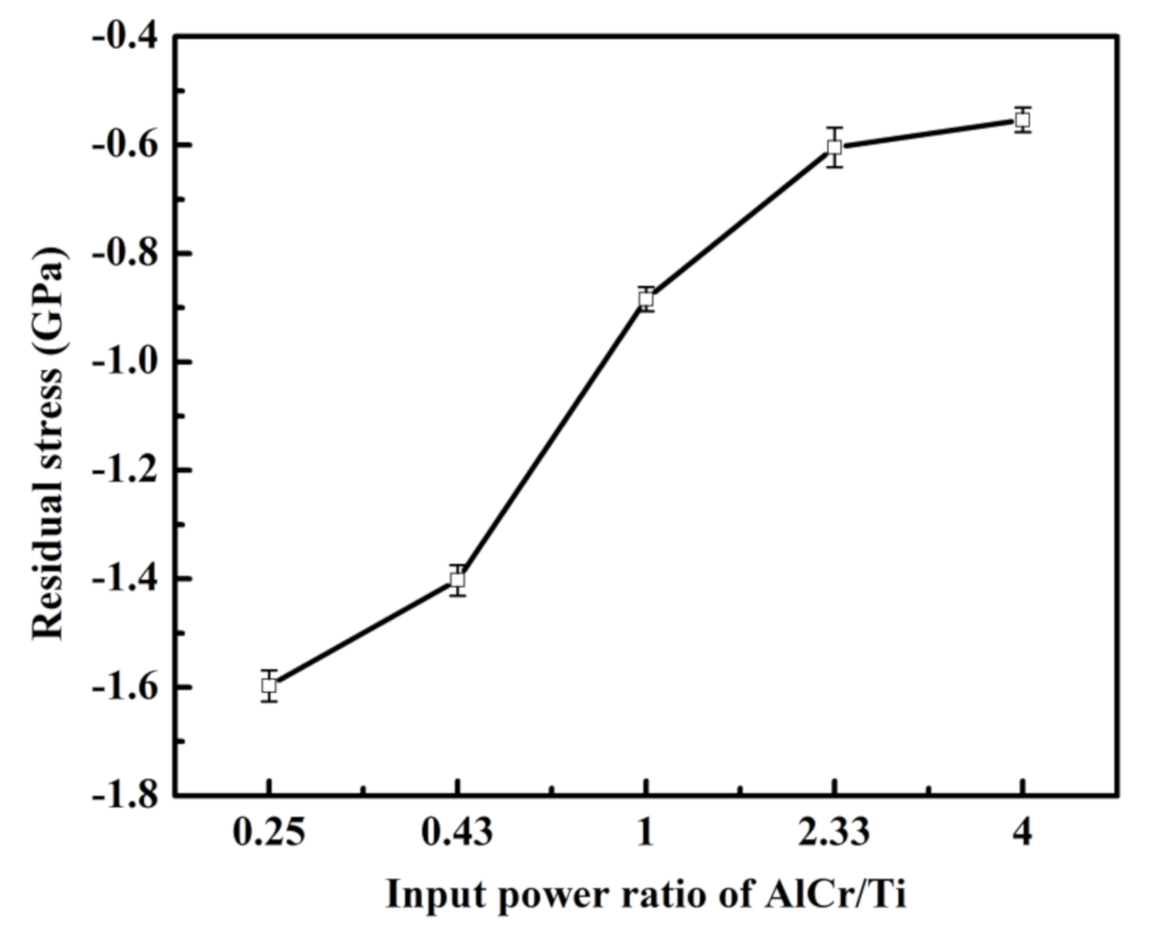
Figure 8 shows the hardness and elastic modulus of five coatings using various input power ratios of the AlCr/Ti target. It is obvious that increasing the input power ratio from 0.25 to 4 leads to a decrease in hardness from 28.7 to 24.6 GPa. SEM and TEM results indicate that this effect can be attributed to the increase of grain size from 40 to 60 nm and column width from 43.2 to 55.3 nm. XRD results reveal that the TiN phase is formed when the input power ratio of the AlCr/Ti target is decreased to below 1. Thus, increasing the input power of the AlCr target causes the gradual disappearance of the TiN phase and favors the formation of AlN due to the composition change of AlTiCrN from Al35Ti65 to Al86Ti14. This phase structure evolution leads to a corresponding decrease in the hardness of the AlTiCrN coatings because the hardness of the TiN coating (17.4 GPa) is higher than that of the AlN coating (13.6 GPa) [33]. Increasing the input power ratio of the AlCr/Ti target also increases the Young’s modulus from 255.3 to 287.3 GPa and decreases the Ti content from 26% to 5%. Although a high hardness is generally associated with a high Young’s modulus, these values are not positively correlated in this work because the differing E values could have been affected by the changing coating thickness [34]. After conducting indentation tests, Koutná et al. [35] discovered that the Young’s modulus of (111)-AlN coatings exceeded that of the (111)-TiN coatings. Chen et al. [30] found that the Young’s modulus of the coatings with a high Ti content were significantly lower than that of the coatings without Ti, which can probably be attributed to the grain refinement; a similar result was also obtained in this study. Previous studies [36] reported that the hardness of the AlCrN films (31 GPa) exceeded that of TiAlN (27 GPa); however, the Young’s modulus of AlCrN (470 GPa) was lower than that of TiAlN (527 GPa). As we observe individually, the hardness and Young’s modulus values are not very informative regarding the mechanical properties of the thin films. The qualitative characteristics of the mechanical property of a thin film must be assessed in terms of the relationship between these two values. As listed in Table 3, we assessed the potential of coatings for tribological applications by calculating the H/E (Hardness/Young’s modulus) ratios, the indicator for wear resistance of the coating [37]. A decreasing tendency can be seen for the H/E values of 0.112, 0.112, 0.105, 0.096, and 0.096, with respect to the increase of the input power ratios for the AlCr/Ti target from 0.25, 0.43, 1, 2.33, to 4, respectively. The best mechanical properties are obtained when the input power ratio of the AlCr/Ti target is fixed at 0.25. As illustrated in Figure 9, residual stress in the five coatings increased with the input power ratio of the AlCr/Ti target. High hardness in a thin film is generally accompanied by high residual stress [38]. In this work, the higher hardness values correspond to higher residual stresses. Note that the residual stress in the AlTiCrN coatings can be related to the thickness of the coatings. Pang et al. [39] explored a highly compressive average residual stress for thinner TiN films, whereas the residual stress decreased for thicker films.

4. Conclusions

This study investigated the effects of the input power ratio of AlCr/Ti targets on the chemical composition, phase, microstructure, and mechanical properties of the AlTiCrN coatings deposited via high-power impulse magnetron sputtering. We fabricated a hard coating system of AlTiCrN containing either a high Al ratio or a high Ti ratio. EPMA analysis revealed that the composition of the coating was determined by the composition and the peak power density of the target. The high ionization of the sputtered atoms was produced during the HiPIMS process, which is beneficial to increase the Ti content in the coating. The TiN and AlTiN phases were observed in the coatings with a high Ti content, whereas the AlN, CrN, and AlCrN phases were found in coatings containing a high Al content. The deposition rate and final thickness depended on the differential sputtering yields of Al, Ti, and Cr elements. Grain refinement and residual stress were related to the thickness of the AlTiCrN coatings. The Al19Ti20Cr7N55 coating presented the highest hardness of 28.9 GPa and H/E ratio of 0.112, which can be attributed to the composition, phase difference (the hardness of TiN is higher than AlN), and refined microstructure (crystallite size decreased from 55.26 to 43.18 nm) of this coating.

Author Contributions

Data curation, C.-Y.L.; investigation, C.-Y.L. and J.-F.T.; methodology, F.-C.Y.; project administration, C.-L.C.; resources, C.-L.C.; software, F.-C.Y.; writing—original draft, J.-F.T.; writing—review & editing, J.-F.T. and C.-L.C. All authors have read and agreed to the published version of the manuscript.

Funding

The authors would like to extend their deepest thanks to the Ministry of Science and Technology, Taiwan, R.O.C for financially supporting this research project under Grant No. MOST 109-2221-E-131-019- and MOST 109-2622-E-131-003-CC3.

Institutional Review Board Statement

Not applicable.

Informed Consent Statement

Not applicable.

Data Availability Statement

Data sharing not applicable.

Acknowledgments

The authors would like to extend heartfelt thanks for the use of the FE-EPMA (JXA-iHP200F) apparatus at the Instrument Center of National Tsing Hua University, the TEM (JEM-2100) apparatus at the Advanced Instrument Center of National Yunlin University of Science and Technology and the HR-SEM (Hitachi SU8000) apparatus at the Instrument Center of National Cheng Kung University.

Conflicts of Interest

The authors declare no conflict of interest.

References

  1. Birol, Y. Sliding wear of CrN, AlCrN and AlTiN coated AISI H13 hot work tool steels in aluminium extrusion. Tribol. Int. 2013, 57, 101–106. [Google Scholar] [CrossRef]
  2. Cai, F.; Yang, Q.; Huang, X.; Wei, R. Microstructure and corrosion behavior of CrN and CrSiCN coatings. J. Mater. Eng. Perform. 2010, 19, 721–727. [Google Scholar] [CrossRef]
  3. Kalin, M.; Jerina, J. The effect of temperature and sliding distance on coated (CrN, TiAlN) and uncoated nitrided hot-work tool steels against an aluminium alloy. Wear 2015, 330, 371–379. [Google Scholar] [CrossRef]
  4. Mohammadpour, E.; Jiang, Z.-T.; Altarawneh, M.; Xie, Z.; Zhou, Z.-f.; Mondinos, N.; Kimpton, J.; Dlugogorski, B.Z. Predicting high temperature mechanical properties of CrN and CrAlN coatings from in-situ synchrotron radiation X-ray diffraction. Thin Solid Film. 2016, 599, 98–103. [Google Scholar] [CrossRef] [Green Version]
  5. Liu, C.B.; Pei, W.; Huang, F.; Chen, L. Improved mechanical and thermal properties of CrAlN coatings by Si solid solution. Vacuum 2016, 125, 180–184. [Google Scholar] [CrossRef]
  6. Wang, Q.; Zhou, F.; Yan, J. Evaluating mechanical properties and crack resistance of CrN, CrTiN, CrAlN and CrTiAlN coatings by nanoindentation and scratch tests. Surf. Coat. Technol. 2016, 285, 203–213. [Google Scholar] [CrossRef]
  7. Soares, T.; Aguzzoli, C.; Soares, G.; Figueroa, C.; Baumvol, I. Physicochemical and mechanical properties of crystalline/amorphous CrN/Si3N4 multilayers. Surf. Coat. Technol. 2013, 237, 170–175. [Google Scholar] [CrossRef] [Green Version]
  8. Mo, J.; Zhu, M.; Lei, B.; Leng, Y.; Huang, N. Comparison of tribological behaviours of AlCrN and TiAlN coatings—Deposited by physical vapor deposition. Wear 2007, 263, 1423–1429. [Google Scholar] [CrossRef]
  9. Fox-Rabinovich, G.; Beake, B.; Endrino, J.; Veldhuis, S.; Parkinson, R.; Shuster, L.; Migranov, M. Effect of mechanical properties measured at room and elevated temperatures on the wear resistance of cutting tools with TiAlN and AlCrN coatings. Surf. Coat. Technol. 2006, 200, 5738–5742. [Google Scholar] [CrossRef]
  10. Durmaz, Y.M.; Yildiz, F. The wear performance of carbide tools coated with TiAlSiN, AlCrN and TiAlN ceramic films in intelligent machining process. Ceram. Int. 2019, 45, 3839–3848. [Google Scholar] [CrossRef]
  11. Tillmann, W.; Lopes Dias, N.F.; Stangier, D.; Gelinski, N. Tribological performance of PVD film systems against plastic counterparts for adhesion-reducing application in injection molds. Coatings 2019, 9, 588. [Google Scholar] [CrossRef] [Green Version]
  12. Gilewicz, A.; Jedrzejewski, R.; Myslinski, P.; Warcholinski, B. Structure, morphology, and mechanical properties of AlCrN coatings deposited by cathodic arc evaporation. J. Mater. Eng. Perform. 2019, 28, 1522–1531. [Google Scholar] [CrossRef] [Green Version]
  13. Liu, H.; Yang, F.-C.; Tsai, Y.-J.; Wang, X.; Li, W.; Chang, C.-L. Effect of modulation structure on the microstructural and mechanical properties of TiAlSiN/CrN thin films prepared by high power impulse magnetron sputtering. Surf. Coat. Technol. 2019, 358, 577–585. [Google Scholar] [CrossRef]
  14. Zhang, Q.; Wu, Z.; Xu, Y.X.; Wang, Q.; Chen, L.; Kim, K.H. Improving the mechanical and anti-wear properties of AlTiN coatings by the hybrid arc and sputtering deposition. Surf. Coat. Technol. 2019, 378, 125022. [Google Scholar] [CrossRef]
  15. Samuelsson, M.; Lundin, D.; Jensen, J.; Raadu, M.A.; Gudmundsson, J.T.; Helmersson, U. On the film density using high power impulse magnetron sputtering. Surf. Coat. Technol. 2010, 205, 591–596. [Google Scholar] [CrossRef] [Green Version]
  16. Polcar, T.; Cavaleiro, A. Structure and tribological properties of AlCrTiN coatings at elevated temperature. Surf. Coat. Technol. 2011, 205, S107–S110. [Google Scholar] [CrossRef]
  17. Fox-Rabinovich, G.; Yamomoto, K.; Veldhuis, S.; Kovalev, A.; Dosbaeva, G. Tribological adaptability of TiAlCrN PVD coatings under high performance dry machining conditions. Surf. Coat. Technol. 2005, 200, 1804–1813. [Google Scholar] [CrossRef]
  18. Tam, P.L.; Zhou, Z.; Shum, P.W.; Li, K. Structural, mechanical, and tribological studies of Cr–Ti–Al–N coating with different chemical compositions. Thin Solid Film. 2008, 516, 5725–5731. [Google Scholar] [CrossRef]
  19. Fernandes, F.; Danek, M.; Polcar, T.; Cavaleiro, A. Tribological and cutting performance of TiAlCrN films with different Cr contents deposited with multilayered structure. Tribol. Int. 2018, 119, 345–353. [Google Scholar] [CrossRef]
  20. Liu, H.; Tang, J.-F.; Wang, X.; Li, W.; Chang, C.-L. Effects of nitrogen-argon flow ratio on the microstructural and mechanical properties of TiAlSiN/CrN multilayer coatings prepared using high power impulse magnetron sputtering. J. Vac. Sci. Technol. A Vac. Surf. Film. 2019, 37, 051501. [Google Scholar] [CrossRef]
  21. Gudmundsson, J.; Brenning, N.; Lundin, D.; Helmersson, U. High power impulse magnetron sputtering discharge. J. Vac. Sci. Technol. A Vac. Surf. Film. 2012, 30, 030801. [Google Scholar] [CrossRef] [Green Version]
  22. Greczynski, G.; Hultman, L. Time and energy resolved ion mass spectroscopy studies of the ion flux during high power pulsed magnetron sputtering of Cr in Ar and Ar/N2 atmospheres. Vacuum 2010, 84, 1159–1170. [Google Scholar] [CrossRef] [Green Version]
  23. Li, Z.; Munroe, P.; Jiang, Z.-T.; Zhao, X.; Xu, J.; Zhou, Z.-F.; Jiang, J.-Q.; Fang, F.; Xie, Z.-H. Designing superhard, self-toughening CrAlN coatings through grain boundary engineering. Acta Mater. 2012, 60, 5735–5744. [Google Scholar] [CrossRef]
  24. Tritremmel, C.; Daniel, R.; Lechthaler, M.; Polcik, P.; Mitterer, C. Influence of Al and Si content on structure and mechanical properties of arc evaporated Al–Cr–Si–N thin films. Thin Solid Film. 2013, 534, 403–409. [Google Scholar] [CrossRef]
  25. Wang, L.; Zhang, G.; Wood, R.; Wang, S.; Xue, Q. Fabrication of CrAlN nanocomposite films with high hardness and excellent anti-wear performance for gear application. Surf. Coat. Technol. 2010, 204, 3517–3524. [Google Scholar] [CrossRef]
  26. Andrievski, R.; Anisimova, I.; Anisimov, V.; Makarov, V.; Popova, V. Grain size and recrystallization of TiN, ZrN, NbN, and CrN alloyed and multilayer films. Thin Solid Film. 1995, 261, 83–86. [Google Scholar] [CrossRef]
  27. Lewin, E.; Loch, D.; Montagne, A.; Ehiasarian, A.P.; Patscheider, J. Comparison of Al–Si–N nanocomposite coatings deposited by HIPIMS and DC magnetron sputtering. Surf. Coat. Technol. 2013, 232, 680–689. [Google Scholar] [CrossRef]
  28. Ohring, M. The materials science of thin films. Appl. Opt. 1992, 31, 7162. [Google Scholar]
  29. Kimura, A.; Hasegawa, H.; Yamada, K.; Suzuki, T. Effects of Al content on hardness, lattice parameter and microstructure of Ti1−xAlxN films. Surf. Coat. Technol. 1999, 120, 438–441. [Google Scholar] [CrossRef]
  30. Xu, Y.; Chen, L.; Liu, Z.; Pei, F.; Du, Y. Influence of Ti on the mechanical properties, thermal stability and oxidation resistance of Al–Cr–N coatings. Vacuum 2015, 120, 127–131. [Google Scholar] [CrossRef]
  31. Tang, J.-F.; Lin, C.-Y.; Yang, F.-C.; Chang, C.-L. Influence of nitrogen content and bias voltage on residual stress and the tribological and mechanical properties of CrAlN films. Coatings 2020, 10, 546. [Google Scholar] [CrossRef]
  32. Fan, Q.-X.; Wang, T.-G.; Liu, Y.-M.; Wu, Z.-H.; Zhang, T.; Li, T.; Yang, Z.-B. Microstructure and corrosion resistance of the AlTiN coating deposited by arc ion plating. Acta Metall. Sin. (Engl. Lett.) 2016, 29, 1119–1126. [Google Scholar] [CrossRef] [Green Version]
  33. Tang, P.; Song, R.; Chai, G.; Mao, J. Microstructure and nanoindentation hardness of TiN/AlN multilayer films prepared by pulsed laser deposition. Surf. Eng. 2012, 28, 165–170. [Google Scholar] [CrossRef]
  34. Bull, S. Microstructure and indentation response of TiN coatings: The effect of measurement method. Thin Solid Film. 2019, 688, 137452. [Google Scholar] [CrossRef]
  35. Koutná, N.; Řehák, P.; Chen, Z.; Bartosik, M.; Fallmann, M.; Černý, M.; Zhang, Z.; Friák, M.; Šob, M.; Mayrhofer, P.H. Correlating structural and mechanical properties of AlN/TiN superlattice films. Scr. Mater. 2019, 165, 159–163. [Google Scholar] [CrossRef]
  36. Kumar, T.S.; Prabu, S.B.; Manivasagam, G.; Padmanabhan, K. Comparison of TiAlN, AlCrN, and AlCrN/TiAlN coatings for cutting-tool applications. Int. J. Miner. Metall. Mater. 2014, 21, 796–805. [Google Scholar] [CrossRef]
  37. Leyland, A.; Matthews, A. On the significance of the H/E ratio in wear control: A nanocomposite coating approach to optimised tribological behaviour. Wear 2000, 246, 1–11. [Google Scholar] [CrossRef]
  38. Jiang, W.; Luo, Y.; Zhang, G.; Woo, W.; Tu, S. Experimental to study the effect of multiple weld-repairs on microstructure, hardness and residual stress for a stainless steel clad plate. Mater. Des. 2013, 51, 1052–1059. [Google Scholar] [CrossRef]
  39. Zhang, L.; Yang, H.; Pang, X.; Gao, K.; Volinsky, A.A. Microstructure, residual stress, and fracture of sputtered TiN films. Surf. Coat. Technol. 2013, 224, 120–125. [Google Scholar] [CrossRef]
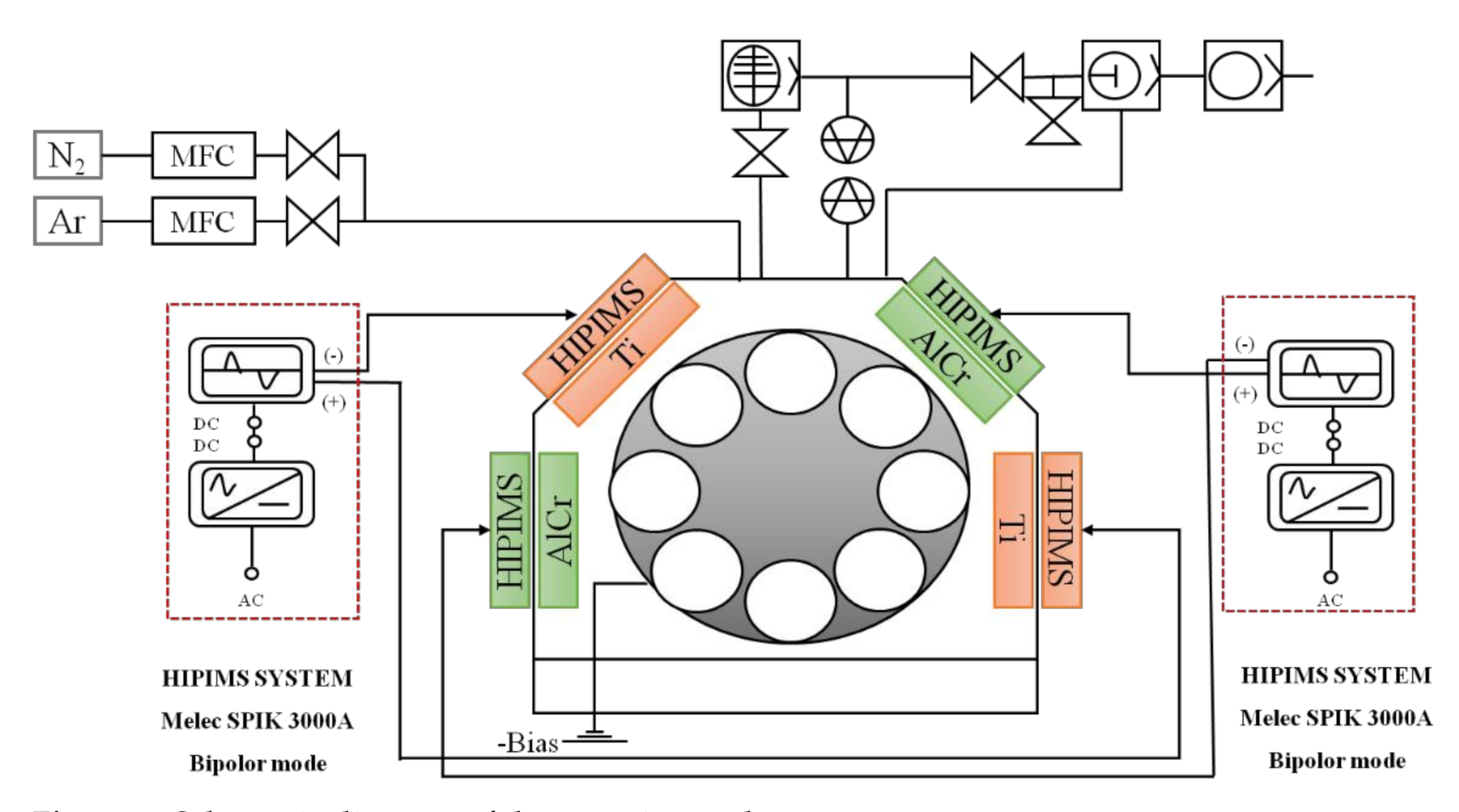
Figure 1. Schematic diagram of the experimental apparatus.
Coatings 11 00826 g001
Figure 2. The relationship between (a) chemical composition, input power ratio of AlCr/Ti target and N/(Al + Cr +Ti) ratio and (b) the tendency of Ti, Al, and Cr contents in HiPIMS and MPP regions with respect to the input power ratio of AlCr/Ti target.
Coatings 11 00826 g002
Figure 3. Top-view SEM images of the AlTiCrN coatings deposited under five different input power ratios.
Coatings 11 00826 g003
Figure 4. Cross-sectional SEM images of the AlTiCrN coatings deposited under five different input power ratios.
Coatings 11 00826 g004
Figure 5. Thickness and deposition ratios of the AlTiCrN coatings as a function of various input power ratios.
Coatings 11 00826 g005
Figure 6. XRD patterns obtained from the AlTiCrN coatings deposited using various AlCr:Ti input power ratios.
Coatings 11 00826 g006
Figure 7. Cross-sectional TEM images of (a) #1, (b) #5 and SAED patterns of (c) #1, and (d) #5 coatings fabricated using the input power ratios of the AlCr/Ti target 0.25 and 4.
Coatings 11 00826 g007
Figure 8. The hardness (black line) and Young’s modulus (blue line) of the AlTiCrN coatings deposited under various input power ratios of the AlCr/Ti target.
Coatings 11 00826 g008
Figure 9. Residual stress of the AlTiCrN coatings deposited under various AlCr:Ti input power ratios.
Coatings 11 00826 g009
Table 1. Experiment parameters of five AlTiCrN coatings deposited by the HiPIMS technology.
Sample Designation#1#2#3#4#5
Parameter
Input power of AlCr target (kW)0.500.751.251.752.00
Input power of Ti target (kW)2.001.751.250.750.50
Input power ratio of AlCr/Ti target0.250.431.002.334.00
Target-substrate distance (cm) 10
Operating pressure (Pa)0.53
Deposition time of the AlTiCrN coating (min)130
Duty cycle (%)3
DC bias voltage (V)−45
Pulse frequency (Hz)200
Pulse on-time/off-time (μs)150/4850
Table 2. The discharge characterizations of Ti and AlCr targets operated by the HiPIMS technology.
Input Power Ratio of
AlCr/Ti
Input Power of AlCr
(kW)
Peak Power Density of AlCr
(W/cm2)
Input Power of Ti
(kW)
Peak Power Density of Ti
(W/cm2)
0.250.52452705
0.430.753421.75683
11.255231.25627
2.331.756410.75365
427040.5231
Table 3. The mechanical properties and chemical composition of the AlTiCrN coatings deposited under various AlCr:Ti input power ratios.
Sample
Designation
Input Power Ratio of
AlCr/Ti
CompositionsAlxTi1−xCrystallite
Size
(nm)
Hardness
(GPa)
Young’s
Modulus
(GPa)
H/EResidual
Stress
(GPa)
#10.25Al14Ti26Cr5N55Al35Ti6514.928.7255.30.112−1.60
#20.43Al19Ti20Cr7N54Al47Ti5316.028.9258.90.112−1.40
#31Al25Ti13Cr9N53Al66Ti3417.928.6272.20.105−0.88
#42.33Al29Ti8Cr11N52Al78Ti2218.026.6275.80.096−0.60
#54Al32Ti5Cr12N51Al86Ti1418.724.6287.30.086−0.55
Publisher’s Note: MDPI stays neutral with regard to jurisdictional claims in published maps and institutional affiliations.