Article

Deformation Mechanisms of NiP/Ni Composite Coatings on Ductile Substrates

1
Beijing Advanced Innovation Center for Materials Genome Engineering, School of Materials Science and Engineering, University of Science and Technology Beijing, Beijing 100083, China
2
Science and Technology on Reactor Fuel and Materials Laboratory, Nuclear Power Institute of China, Chengdu 610213, China
3
Guangdong Province Key Laboratory of Durability for Marine Civil Engineering, School of Civil Engineering, Shenzhen University, Shenzhen 518060, China
4
Department of Mechanical Engineering, University of South Florida, 4202 E. Fowler Ave. ENG030, Tampa, FL 33620, USA
*
Authors to whom correspondence should be addressed.
These authors contributed equally to this work.
Coatings 2021, 11(7), 834; https://doi.org/10.3390/coatings11070834
Submission received: 23 June 2021 / Revised: 6 July 2021 / Accepted: 7 July 2021 / Published: 10 July 2021
(This article belongs to the Section Corrosion, Wear and Erosion)

Abstract

:
NiP/Ni composite coatings with different thicknesses were prepared on coarse-grained Ni substrates by electrodeposition. The tensile tests show that compared with the substrate, the toughness and strength of the samples with multilayer composite coatings are greatly improved. The uniform elongation is increased from 24% to 43%, and the yield strength is increased from 108 to 172 MPa. In the deformation process, the geometrically necessary dislocations accumulate, resulting in long-range back stress, leading to strain hardening, showing synergistic strength and ductility. The mechanical properties of composite coatings are strongly affected by the layer thickness. Molecular dynamics studies show that there is a more uniform distribution of the shear strain in thinner coatings, and the propagation of shear transformation zones (STZs) is restrained, preventing the formation of a large shear band. With the decrease of thickness, the deformation of the NiP layer changes from shear fracture to the coexistence of uniform deformation and shear deformation. The interface resistance of the multilayer structure increases the resistance of crack propagation and alleviates the effects of NiP layer cracking on substrate cracking. Multilayer amorphous/crystalline coatings therefore may increase the toughness of the Ni substrate.

1. Introduction

Amorphous coatings have many industrial applications due to their high strength and hardness, excellent wear, and corrosion resistance [1,2,3,4,5]. However, amorphous alloys usually suffer from fast propagating shear bands during deformation, leading to brittle fracture. Guo et al. [6] discovered that the brittle coating can induce local high strain rate loading of the substrate when the brittle coating fractures with fast crack propagation. The damage becomes more severe as the coating thickness increases. In actual application, to ensure corrosion protection provided by the amorphous coating, its thickness is usually tens of micrometers, and it is a thickness prone to cracking in brittle coating, which could seriously affect the reliability of the substrate.
Recent experimental studies have shown that adopting an amorphous/crystalline composite structure could greatly enhance the ductility of the amorphous layers while retaining high strength and corrosion resistance. Wang et al. [7] found that in the process of tensile deformation, the nanolaminate amorphous layers can absorb the volume and energy transferred by dislocations, and the amorphous-crystalline interfaces show unique inelastic shear (slip) transfer characteristics, improving the crystalline copper/copper–zirconium glass nanolaminate tensile ductility. Lu et al. [8] observed that under the constraint of a ductile Ni substrate, homogeneous plastic flow occurred in the amorphous film simultaneously with cracking or the formation of shear bands. Ren et al. [9] reported that the NiP/Ni bilayered surface coating can improve the compressive ductility of the Zr-based amorphous alloy pillars. The Ni coatings absorb the mechanical energy due to the deformation of the “soft” crack buffer zone, while the NiP coatings impede the rapid propagation of shear bands as hard regions. The combination of the soft and hard regions alters the propagation direction of shear bands and assists the multiplication of shear bands, resulting in the wavelike appearance of shear bands and the significant improvement of the ductility of the pillars. Wang et al. [10] investigated the deformation behavior of an Fe-based alloy coated with a double-layered ductile Ni coating and found that the propagation of amorphous shear bands became more stable. Therefore, combining the amorphous coating and the tough crystalline coating to obtain an amorphous/crystalline composite coating is expected to prevent rapid shear bands and the embrittlement of the substrate.
It is very difficult to observe the plastic deformation of the amorphous/crystalline composites in situ at the atomic scale, so molecular dynamics (MD) simulations are widely used [11,12]. For example, Barman et al. [13] investigated the plastic deformation of a Cu(111)/Cu46Zr54 amorphous/crystalline composite under uniaxial compression by MD simulations. It was found that the nucleation of shear bands in the amorphous layer is triggered by the dislocations of the adjacent crystalline copper layer traveling across the amorphous/crystalline interface (ACI). Therefore, it is believed that the shear band formation mechanisms in a constraint-free amorphous film and a constrained amorphous film are different. Without constraints, the shear bands usually nucleate from one location and propagate freely in the amorphous phase, while the shear bands in the amorphous layer of the amorphous/crystalline composite material, which are triggered by dislocations from the ACI, are more dispersed. Moreover, due to the constraints exerted by the crystalline layer, the shear band cannot develop into one large band that could fracture the whole structure.
In recent years, the effects of layer thickness on amorphous/crystalline composites have also been reported. The strengthening and toughening of amorphous/crystalline nanocomposites can be realized by adjusting the layer thickness [14,15]. Guo et al. [16] and Zhang et al. [17] used the confined layer slip (CLS) model to explain the size effects of the amorphous/crystalline nanolaminates. Then, Luan et al. [18] found that when the thickness of the amorphous/crystalline Cu50Zr50/Cu layer is 4–5 nm, the CSL model underestimates the results due to the amorphous layer effects on the overall mechanical properties. The crystalline layer was easily destroyed when layer thickness was less than 4 nm. The shear transformation zone (STZs) and dislocations transmitted the global strain of the sample and resulted in deformation and softening of the sample. However, the basic understanding of the plastic deformation mechanism and micro details of the amorphous/crystalline multilayer on the ductile substrate is greatly lacking, and this area still needs to be studied.
In this paper, amorphous NiP/crystalline Ni multilayer composite coatings with a thickness of 2.5, 5, and 7.5 μm were prepared on coarse-grained Ni substrates by electrodeposition. The plastic deformation and fracture behavior of the NiP/Ni multilayer composite coating under uniaxial tensile load were investigated by X-ray diffraction (XRD) and scanning electron microscopy (SEM). The details of the deformation process were further analyzed by molecular dynamics simulations. It was found that the elongation of CG Ni can be improved by depositing a NiP/Ni multilayer composite coating, and the ductility of the sample with a thinner NiP/Ni coating is higher. The thinner the composite layer is, the more uniform the shear strain distribution is, and the propagation of STZ is restrained, which can prevent the formation of a large shear band and improve ductility.

2. Experimental

2.1. Sample Preparation

The composite coating specimens consisting of NiP/Ni multilayers and an annealed coarse-grained Ni substrate were synthesized by electrodeposition. High purity commercial Ni thin substrates were machined and polished into dog-bone shape with a gauge cross-section of ~0.42 mm × 4 mm and a gauge length of 10 mm, which were annealed at 773 K for two hours to eliminate the textured microstructure. Alternating polycrystalline Ni and amorphous NiP layers were deposited on the CG Ni substrates. The electrolyte for NiP deposition contained nickel sulfate (300 g/L), nickel chloride (45 g/L), boric acid (40 g/L), phosphorous acid (20 g/L), and sodium dodecyl sulfate (0.25 g/L), maintained at a pH value of 2 ± 0.2 and 343 ± 2 K [19]. The crystalline Ni was deposited using an electrolyte consisting of nickel sulfate (250 g/L), nickel chloride (40 g/L), boric acid (35 g/L), sodium dodecyl sulfate (0.05 g/L), saccharin (0.8 g/L), and lanthanum chloride (1.6 g/L), maintained at a pH value of 4 ± 0.2 and 328 ± 2 K. The applied current density was 30 and 35 mA/cm2 for depositing NiP and Ni, respectively. The layer thickness was controlled by the deposition time. Three sets of samples were produced: (i) twelve layers of 2.5 μm NiP/Ni coating, (ii) six layers of 5 μm NiP/Ni coating, and (iii) four layers of 7.5 μm NiP/Ni coating. Additionally, the total coating thickness was about 30 μm each time.

2.2. Tensile Tests

Uniaxial tensile tests were performed using the WDW-10E universal testing machine (Ji'nan Shijin Group Co. Ltd., Jinan, China) with a maximum load of 3 kN and 10−3 N force resolution. All tensile tests were performed at room temperature at the strain rate of 3 × 10⁻⁴ s−1.

2.3. Microstructure Characterization

The microstructure of the Ni and NiP layers was characterized by X-ray diffraction (XRD, Rigaku D/Max 2550X, Rigaku Corporation, Tokyo, Japan) with Cu Kα radiation. The grazing incidence method at a 2° angle was adopted. After the tensile test, the fracture morphology was examined by SEM (GeminiSEM 300, Carl Zeiss Microscopy GmbH, Jena, Germany).

2.4. MD Simulations

The embedded atom method (EAM) potential developed by Sheng et al. [20] was used to describe the interatomic interactions of the amorphous NiP layer and the crystalline Ni. The MD simulations were conducted by the open-source Large-scale Atomic/Molecular Massively Parallel Simulator (LAMMPS). The atomic configurations of the amorphous NiP were obtained through quenching a fully melted equimolar NiP model from 2000 to 1 K. The cooling rate was 10−12 K·s−1. The polycrystalline Ni layer was built through the Voronoi tessellation method to construct a columnar model containing 4 grains (10 nm diameter) of hexagonal shape within periodic simulation cells. The polycrystal model was then constructed by filling the hexagonal grains with a fully relaxed face-center cubic (FCC) Ni. The <100> orientations of the grains were all aligned along the out-of-plane direction. The NiP/Ni composite was then built by combining the amorphous NiP layer with the polycrystalline Ni layer. The periodic boundary conditions were applied in all directions. Three composite models were built with different layer thicknesses, namely 5, 10, and 15 nm. The composite models were then subjected to tensile loading at the strain rate of 108 s−1 at 300 K.

3. Results

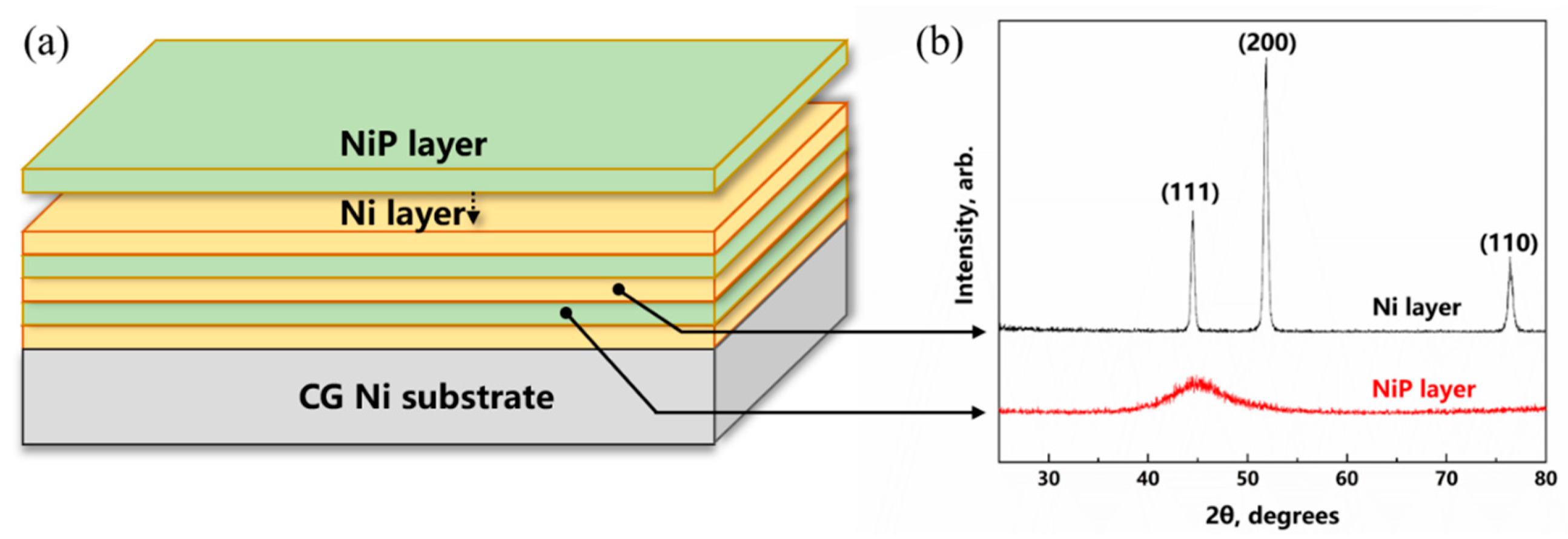
3.1. Microstructure of the Samples

Figure 1a shows a schematic drawing of a sample with a deposited NiP/Ni composite coating. In Figure 1a, the Ni layer is first deposited on the CG-Ni substrate, and then the NiP amorphous layer is deposited. The thickness of the Ni and NiP sublayers is the same, and the total thickness of the composite coating is 30 μm. Three samples with different sublayer thicknesses were prepared. The sublayer thicknesses were 2.5, 5, and 7.5 μm, which was changed by controlling the deposition time. The XRD patterns of the Ni layer and NiP layer are shown in Figure 1b, where the diffracted X-rays from the NiP layer exhibit typical diffuse scattering without any detectable Bragg diffraction reflections, proving an amorphous structure. As for the Ni layer, a strong preferential (200) reflection can be observed. The NiP amorphous layer is more conducive to plastic deformation at the (200) oriented Ni layer, which was discovered by Lu et al. [8].

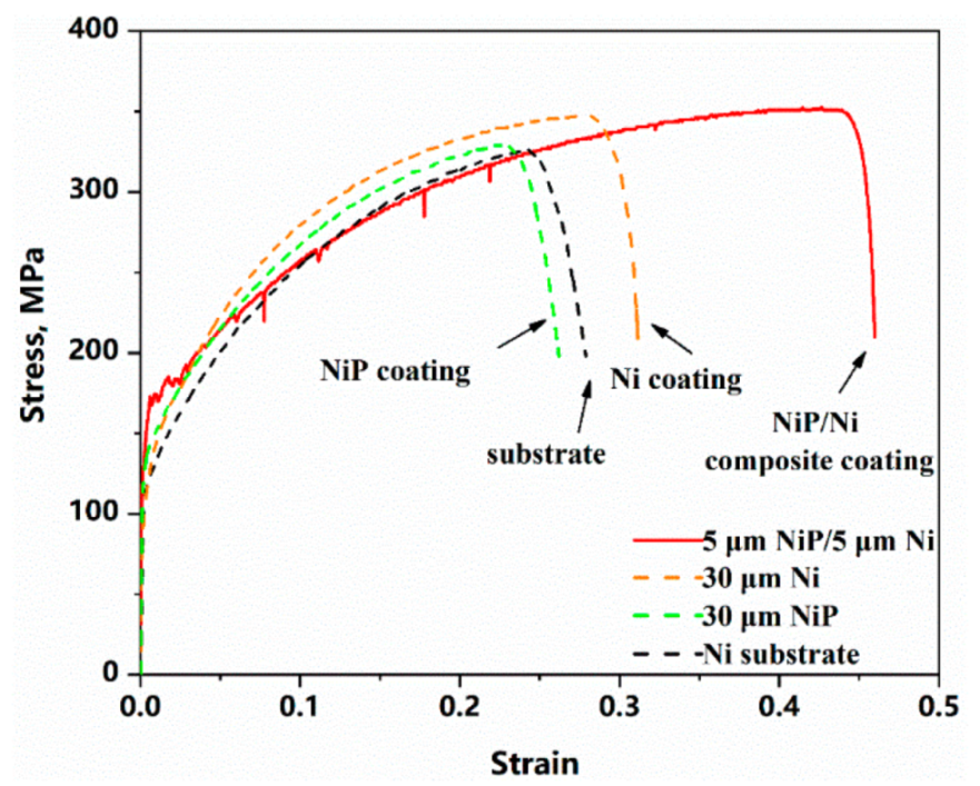
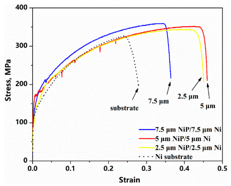
3.2. Mechanical Properties

Figure 2 displays engineering stress–strain curves of four kinds of the specimens with different coatings, including the uncoated CG Ni substrate for comparison. The 30 μm deposited composite coating greatly improved the toughness compared with the uncoated substrate. For the CG Ni substrate without composite coating, the uniform elongation is 24.1%, while under the constraints of the NiP/Ni multilayer composite coating, the uniform elongation is 43.9%, which is an 82.1% increase. The 108 MPa yield strength of the CG Ni substrate is increased to 172 MPa with the composite coating. To reveal the coupling effect of the amorphous/crystalline composite, a 30 μm crystalline Ni coating and an amorphous NiP coating were deposited on the CG Ni substrate for comparison. The elongation of the specimen with Ni coating increased slightly, while the elongation of the specimen with NiP coating decreased. The 30 μm-thick amorphous coatings fractured by shear bands during deformation, causing local crack initiation. The cracks in the brittle amorphous coating can also penetrate the substrate and damage the ductile substrate [21]. The above experimental results show that the elongation of annealed CG Ni can be improved by the deposition of the NiP/Ni multilayer composite coating.
Figure 3 displays the engineering stress–strain curves of the specimen with various thicknesses of each layer (2.5 μm NiP/Ni, 5 μm NiP/Ni, and 7.5 μm NiP/Ni) under tension, including the CG Ni substrate for comparison. The overall mechanical properties are strongly affected by the thickness of the deposited layers. The uniform elongation is 34.6%, 41.3%, and 43.9%, corresponding to the layer thickness of 7.5, 2.5, and 5 μm, respectively.

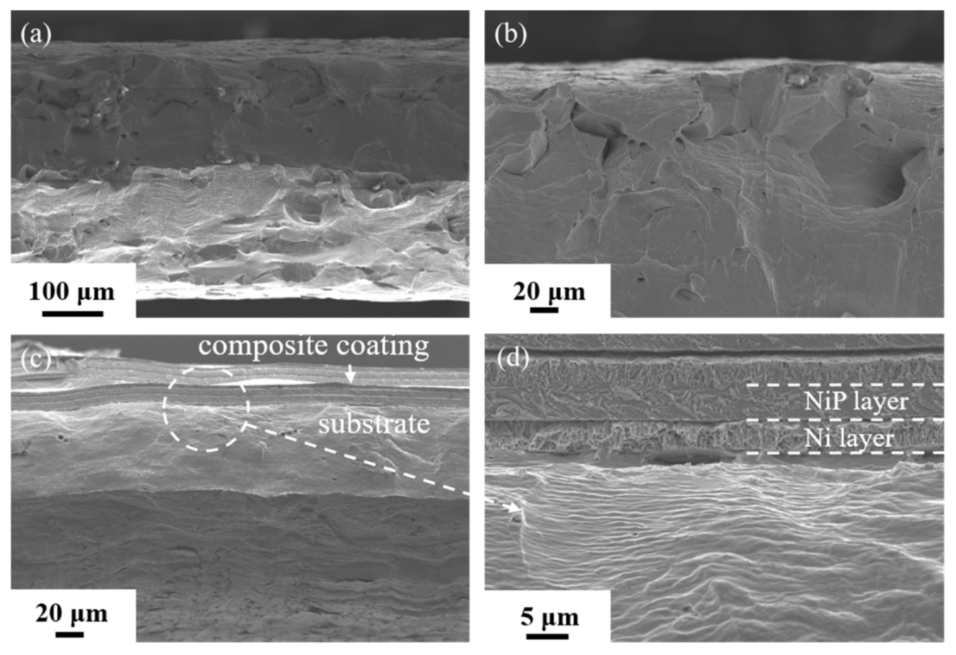
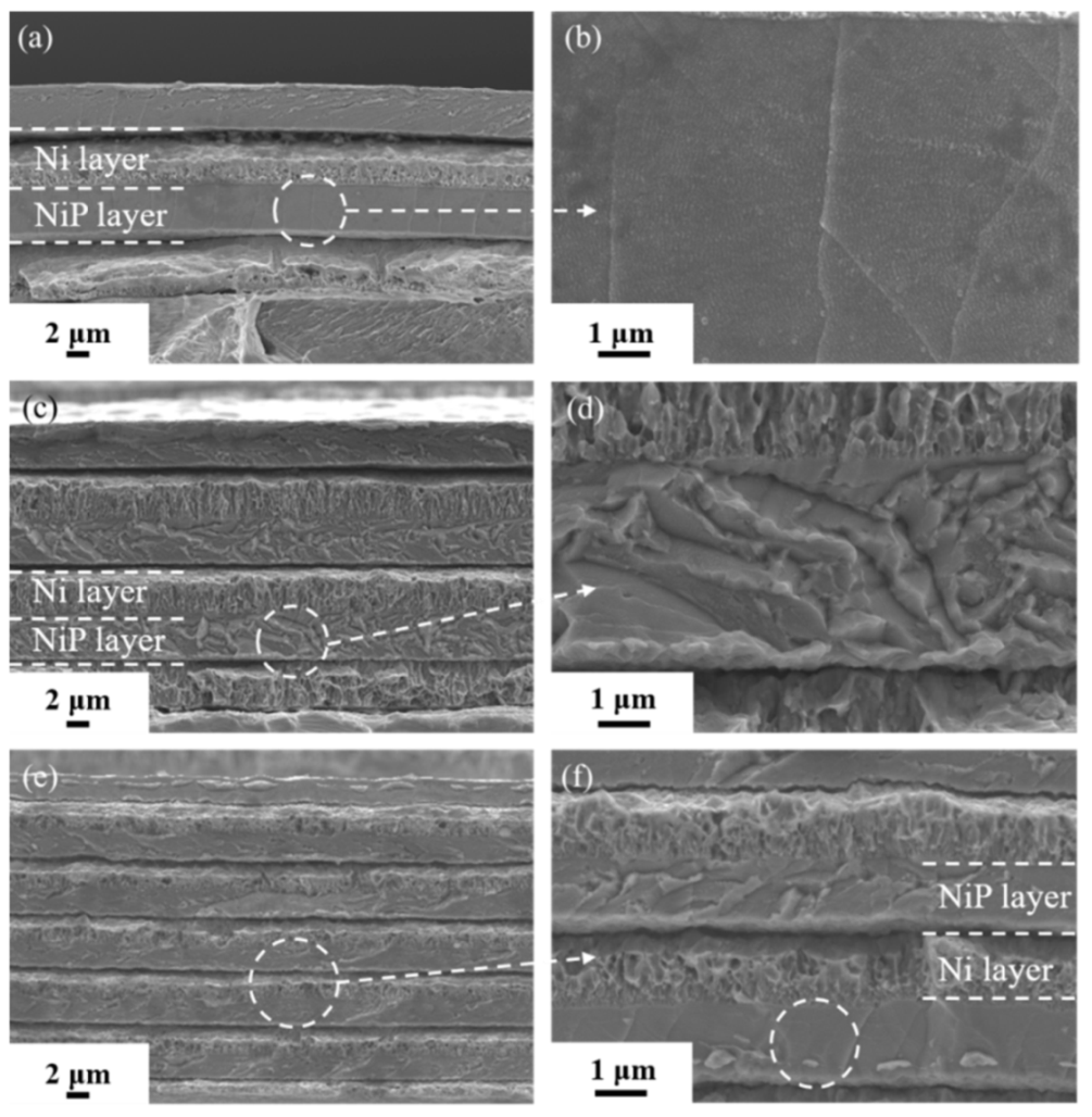
3.3. Fractography Analysis

Figure 4 reveals the representative fracture surfaces of the deposited composite coating specimen and the substrate. The substrate has an irregular oblique fracture morphology in Figure 4a, which is divided into three areas [22]. The fiber region in the middle is the initial part of the fracture where the grains are elongated like fibers. Then, the crack expands rapidly to both sides to form the radical zone. After the crack propagates to the edge of the fracture surface, the shear lip region is formed under plane stress. However, instead of the typical fracture morphology, only fibrous regions can be observed in the fracture of the composite coating specimen. Under the restraint of the coating, the original isometric crystal was elongated into fibers. A wide range of fiber regions indicates excellent tensile plasticity, which is also related to the small size of the specimen. The reason for the different fracture morphology of the two samples is that the stress state of the substrate has changed due to the constraint of the strong and ductile coating [23].
To reveal the deformation mechanism of composite coatings with different structures after tension, the fracture morphology of the specimen coated with different thickness for each layer (7.5 μm NiP/Ni, 5 μm NiP/Ni, 2.5 μm NiP/Ni) is presented in Figure 5. For the 7.5 μm NiP/7.5 μm Ni specimen in Figure 5a,b, the upper and lower NiP layers show a different fracture morphology, owing to the lower layer constrained by a double Ni layer, while the upper layer is only constrained by a single Ni layer. Typical NiP amorphous wavy fractures were observed in the upper layers, multiple cracks, and shear band in the lower layers. For the 5 μm NiP/5 μm Ni specimen in Figure 5c,d, the fracture displays a rugged stair-step shape in the NiP layer, which is quite different from Figure 5b, owing to the thinner NiP layer. For the 2.5 μm NiP/2.5 μm Ni specimen in Figure 5e,f, with the thinnest composite coating per layer, the fracture morphology of the NiP layers shows the coexistence of smooth regions (as shown in the white circle Figure 5f) and heterogeneous stepped cracks. Constrained by the Ni layer, the shear and normal stresses of the NiP layer are decreased on the shear fracture planes of the NiP layer [10], which displays a smooth fracture morphology.
Due to the incompatibility of mechanical properties between the composite coating and the substrate, small cracks may nucleate in the coating or at the interface. As seen in Figure 6a, the curved crack stops at the interface in the 2.5 μm NiP/2.5 μm Ni composite coating. The bending of the crack at the interface of each layer can be observed, which dissipated the energy of the crack and released stress concentration without harming the substrate [24]. However, in Figure 6b, thicker amorphous layers obtained more fracture energy where the crack broke through the barrier of the interface and expanded into the substrate. The damage to the substrate undoubtedly reduced the toughness of the sample.

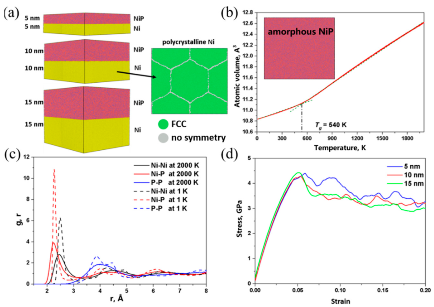
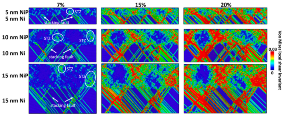
3.4. MD Simulation Results

The atomic structures of the NiP/Ni composite models are shown in Figure 7a. The atomic volume versus temperature curve of the amorphous NiP layer is depicted in Figure 7b. The glass transition temperature is 540 K. Figure 7c shows the evolution of the partial pair-distribution functions before and after quenching. The first peak of the g(r) of the Ni-P pair is the highest, indicating the strong bonding tendency between Ni and P. The absence of a sharp peak in the g(r) of the P-P pair indicates that the P-P bonds cannot be formed. The splitting of the second peaks of g(r) suggests that some short-range ordered structures have been formed.
The tensile stress–strain curves of the three composites are shown in Figure 7d. Composites with different layer thicknesses have similar yield stress but slightly different flow stress, with that of the 5 nm model being the highest, indicating that the lowest layer thickness is the most effective in blocking plastic deformation modes, such as dislocation slip and shear transformation zone activities. The plastic deformation mechanism can be further visualized in Figure 8, where the shear strain distributions are plotted for the three composite models. The shear strain distributions are calculated from the von Mises local shear invariant, taking the atomic configurations before deformation as the references. The von Mises local shear invariant [25] of atom i is calculated as
η i Mises =   η yz 2 + η xz 2 + η xy 2 + ( η yy η zz ) 2 + ( η xx η zz ) 2 + ( η zz η yy ) 2 6
where η is the Green–Lagrangian strain tensor calculated through the atomic strain module in the Open Visualization Tool (OVITO) [26].
The shear strain distribution can give information about dislocations and STZ activities. At 7% strain, stacking faults, which result from the slip of 1/6<112> Shockley partial dislocations, have already nucleated from the ACI and have propagated to the adjacent ACI. As the dislocations reach the ACIs, the shear deformation brought by the dislocations triggers the formation of STZs. As the deformation continues, more dislocations are nucleated from ACIs and then accumulate at ACIs. The STZs triggered by dislocations also propagate, and larger shear bands are formed. Comparing the shear strain distributions of the models with different layer thicknesses, one can see that the shear localization is more severe in models with thicker layers, while the shear strain is more spread and homogeneous in the 5 nm model. It has been established that the amorphous material with a smaller size is less likely to be affected by the shear band instability since the small size inhibits the propagation of STZs and could present the formation of one large shear band that causes the fracture of the material. In Figure 8, one can see that the smaller thickness not only prevents the formation of a large shear band in the amorphous phase but also homogenizes strain distribution in the crystalline phase. The shear strain distribution might explain the higher ductility of the 2.5 μm NiP/Ni and 5 μm NiP/Ni over that of 7.5 μm NiP/Ni.

4. Discussion

4.1. Composite Coating Effects on Deformation

Many studies have shown that the existence of coating can significantly affect the strength and toughness of matrix materials, owing to the differences in elastic modulus, lattice constant, crystal orientation, and other parameters [21,27,28]. As can be seen from the stress–strain curves in Figure 2, the yield strength and the uniform elongation are significantly increased, compared with the uncoated CG Ni. According to the fracture morphology in Figure 4b, even the intergranular fracture can be observed at the edge of the CG Ni. This is due to the grain size of annealed CG Ni being tens of microns and the substrate thickness of 420 μm, thus making it difficult to provide sufficient work hardening. After the coating is deposited, the dislocation originally escaped from the substrate would have been blocked at the interface, and the density of stacking dislocations will increase with strain.
There are two effects of high-density dislocations on the substrate. On the one hand, the deformation of the soft substrate is fully constrained by the strong and ductile composite coating, which leads to the increased generation of the geometrically necessary dislocations (GND) to accommodate the plastic incompatibility. The GNDs produce the long-range back stress [29], which prevents the dislocation source from releasing more dislocations, resulting in strain hardening. This is the reason why the elongated grain of the fiber area can be observed near the interface with the substrate. The back stress is also primarily responsible for the combination of strength and ductility in heterogeneous structures by recent reports [30,31]. The back stress hardening in dual-phase steel delays the strain localization, which exhibits good tensile plastic deformation capacity during tensile deformation [32]. On the other hand, the coating can act as the barrier layer for dislocation overflow, which causes dislocation pileup at the interface. The head of the dislocation pileup will cause great stress concentration and promote matrix cracking. As shown in Figure 6, the fracture of the coating causes damage to the substrate, which will be discussed in Section 4.3.

4.2. Fracture Mechanism of NiP Layers in the Composite Coating

As mentioned above, the magnitude of back stress is related to the degree of plastic incompatibility. As shown in Figure 3, the specimens of different thicknesses of each layer with the same total thickness display various uniform elongations, which means different mechanical properties. By the recent research [19,33], the size effect of the amorphous alloy and the constraint of the nanocrystalline Ni layer contributed to the plastic deformation of the NiP layer, which directly affects the crack propagation in the amorphous layer and is related to the thickness of each layer.
According to Griffith’s crack propagation criterion, if the shear band can be extended in an amorphous layer, the strain energy released by the shear band extension must be greater than or equal to the surface energy to form a fresh surface. Lu et al. [8] calculated and analyzed the conditions of the shear band and crack propagation in amorphous NiP. The critical thickness of the crack in the amorphous layer is 3–4 μm under the constraint of the Ni matrix. However, both the upper and lower NiP layers are constrained by the Ni layer in the NiP/Ni composite coating. Thus, the critical thickness of the NiP layer fracture should be larger, which is consistent with the experimental results in Figure 5a–d. For the 5 μm NiP/5 μm Ni specimen in Figure 5c,d, the NiP fracture pattern has been fully converted to shear fracture. It is worth noting that a significant amount of bending occurs during the propagation of the shear band, which consumes deformation capacity. When the thickness of the amorphous layer was decreased to 2–3 μm, the deformation mechanism of the NiP amorphous layer changed to the coexistence of uniform deformation and shear deformation. In Figure 5e,f, the amorphous fracture presents both shear fracture and the smooth region. The fracture morphology of the smooth region is the result of uniform deformation of the amorphous layer [10].

4.3. Effects of Coating Cracking on Substrate Deformation

As shown in Figure 6b, the cracking of the substrate is directly below the cracking of the coating, which means that the cracking of the coating induces the cracking of the substrate. There is a precedent for brittle coating cracking leading to matrix cracking. The crack in the Ag80Cu20 film extended into the matrix and caused the intergranular fracture of the matrix [34]. The rapid fracture experiments of brittle materials show that the crack propagates rapidly in brittle materials [24]. The crack nucleated in the coating and spread to the interface, resulting in high-speed local loading of the substrate, which led to substrate cracking and damaged the overall plasticity of the specimen. However, in Figure 6a, the crack bends as it propagates through the coating. As a result, when the crack reaches the coating–substrate interface, it cannot continue to expand into the substrate. This is due to the multilayer structure of the specimen with the 2.5 μm NiP/2.5 μm Ni composite coating. When the NiP–Ni interface bonding is strong enough, the crack growth resistance can be increased by the interface resistance, and the crack growth will require additional work. Therefore, a multilayer structure can effectively prevent damage to the coating caused by brittle NiP layer cracking.

5. Conclusions

In this paper, the deformation mechanisms of NiP/Ni composite coatings with different thicknesses on a coarse-grained Ni substrate were investigated by tensile tests and molecular dynamics simulations. The main conclusions are as follows:
  • During the deformation process, the composite coating and the ductile substrate are constrained by each other and deform cooperatively. In this process, the geometrically necessary dislocations accumulate, resulting in long-range back stress, leading to strain hardening, showing synergetic strength and ductility.
  • The critical fracture thickness of the amorphous NiP layer confined by the double Ni layer is larger than the amorphous NiP layer confined by a single Ni layer. With the decrease of the thickness, the distribution of shear strain becomes more uniform, and the expansion of STZ is restrained, which can prevent the formation of a large shear band. The deformation mode changes from shear fracture to the coexistence of uniform deformation and shear deformation.
  • The multilayer structure interface increases the resistance of crack propagation, and the crack bends at the interface, which dissipates the energy of the crack and releases the stress concentration so that the substrate will not be damaged. The fracture energy of thicker coating is higher, and the crack easily expands into the matrix, which reduces the toughness.

Author Contributions

Experiments and writing—original draft, Z.Z. and H.X.; Simulation, X.Z.; Study design, T.G.; Supervision, X.P.; Writing—review and editing, A.A.V. All authors have read and agreed to the published version of the manuscript.

Funding

This work was supported by the National Natural Science Foundation of China (Nos. 51922002 and 51771025) and the Fundamental Research Funds for the Central Universities (No. FRF-TP-17-19-003C1Z).

Institutional Review Board Statement

Not applicable.

Informed Consent Statement

Not applicable.

Data Availability Statement

Not applicable.

Conflicts of Interest

The authors declare no conflict of interest.

References

  1. Zhang, C.; Chan, K.C.; Wu, Y.; Liu, L. Pitting initiation in Fe-based amorphous coatings. Acta Mater. 2012, 60, 4152–4159. [Google Scholar] [CrossRef]
  2. Ma, Y.; Cao, Q.P.; Qu, S.X.; Wang, X.D.; Jiang, J.Z. Effect of structural relaxation on plastic flow in a Ni-Nb metallic glassy film. Acta Mater. 2012, 60, 3667–3676. [Google Scholar] [CrossRef]
  3. Guo, H.; Yan, P.F.; Wang, Y.B.; Tan, J.; Zhang, Z.F.; Sui, M.L.; Ma, E. Tensile ductility and necking of metallic glass. Nat. Mater. 2007, 6, 735–739. [Google Scholar] [CrossRef] [PubMed]
  4. Wang, Q.; Han, P.; Yin, S.; Niu, W.-J.; Zhai, L.; Li, X.; Mao, X.; Han, Y. Current research status on cold sprayed amorphous alloy coatings: A review. Coatings 2021, 11, 206. [Google Scholar] [CrossRef]
  5. Lelevic, A.; Walsh, F.C. Electrodeposition of NiP alloy coatings: A review. Surf. Coat. Technol. 2019, 369, 198–220. [Google Scholar] [CrossRef]
  6. Guo, T.; Chen, Y.; Cao, R.; Pang, X.; He, J.; Qiao, L. Cleavage cracking of ductile-metal substrates induced by brittle coating fracture. Acta Mater. 2018, 152, 77–85. [Google Scholar] [CrossRef]
  7. Wang, Y.; Li, J.; Hamza, A.V.; Barbee, T.W. Ductile crystalline–amorphous nanolaminates. Proc. Natl. Acad. Sci. USA 2007, 104, 11155–11160. [Google Scholar] [CrossRef] [PubMed] [Green Version]
  8. Lu, X.L.; Li, Y.; Lu, L. Co-existence of homogeneous flow and localized plastic deformation in tension of amorphous Ni-P films on ductile substrate. Acta Mater. 2016, 106, 182–192. [Google Scholar] [CrossRef] [Green Version]
  9. Ren, L.W.; Yang, F.Q.; Jiao, Z.M.; Yang, H.J.; Wang, Z.H.; Qiao, J.W. Plasticity enhancement in Ni-P amorphous alloy/Ni/Zr-based metallic glass composites with a sandwich structure. Mater. Sci. Eng. A Struct. Mater. Prop. Microstruct. Process. 2015, 643, 175–182. [Google Scholar] [CrossRef]
  10. Wang, Y.C.; Luo, X.M.; Chen, L.J.; Yang, H.W.; Zhang, B.; Zhang, G.P. Enhancement of shear stability of a Fe-based amorphous alloy using electrodeposited Ni layers. J. Mater. Sci. Technol. 2018, 34, 2283–2289. [Google Scholar] [CrossRef]
  11. Pan, Z.; Rupert, T.J. Amorphous intergranular films as toughening structural features. Acta Mater. 2015, 89, 205–214. [Google Scholar] [CrossRef] [Green Version]
  12. Brandl, C.; Germann, T.C.; Misra, A. Structure and shear deformation of metallic crystalline–amorphous interfaces. Acta Mater. 2013, 61, 3600–3611. [Google Scholar] [CrossRef]
  13. Arman, B.; Brandl, C.; Luo, S.N.; Germann, T.C.; Misra, A.; Cagin, T. Plasticity in Cu(111)/Cu46Zr54 glass nanolaminates under uniaxial compression. J. Appl. Phys. 2011, 110. [Google Scholar] [CrossRef]
  14. Cui, Y.; Shibutani, Y.; Li, S.; Huang, P.; Wang, F. Plastic deformation behaviors of amorphous-Cu50Zr50/crystalline-Cu nanolaminated structures by molecular dynamics simulations. J. Alloy. Compd. 2017, 693, 285–290. [Google Scholar] [CrossRef]
  15. Cheng, B.; Trelewicz, J.R. Design of crystalline-amorphous nanolaminates using deformation mechanism maps. Acta Mater. 2018, 153, 314–326. [Google Scholar] [CrossRef]
  16. Guo, W.; Jägle, E.; Yao, J.; Maier, V.; Korte-Kerzel, S.; Schneider, J.M.; Raabe, D. Intrinsic and extrinsic size effects in the deformation of amorphous CuZr/nanocrystalline Cu nanolaminates. Acta Mater. 2014, 80, 94–106. [Google Scholar] [CrossRef]
  17. Zhang, J.Y.; Liu, G.; Lei, S.Y.; Niu, J.J.; Sun, J. Transition from homogeneous-like to shear-band deformation in nanolayered crystalline Cu/amorphous Cu–Zr micropillars: Intrinsic vs. extrinsic size effect. Acta Mater. 2012, 60, 7183–7196. [Google Scholar] [CrossRef]
  18. Luan, Y.W.; Li, C.H.; Zhang, D.; Li, J.; Han, X.J.; Li, J.G. Plastic deformation mechanisms and size effect of Cu50Zr50/Cu amorphous/crystalline nanolaminate: A molecular dynamics study. Comput. Mater. Sci. 2017, 129, 137–146. [Google Scholar] [CrossRef]
  19. Cuan, X.; Pan, J.; Cao, R.; Lin, Y.; Yao, J.; Wang, Y.; Li, Y. Effect of amorphous layer thickness on the tensile behavior of bulk-sized amorphous Ni-P/crystalline Ni laminates. Mater. Lett. 2018, 218, 150–153. [Google Scholar] [CrossRef]
  20. Sheng, H.W.; Ma, E.; Kramer, M.J. Relating dynamic properties to atomic structure in metallic glasses. JOM 2012, 64, 856–881. [Google Scholar] [CrossRef] [Green Version]
  21. Song, X.T.; Guo, R.P.; Wang, Z.; Wang, X.J.; Yang, H.J.; Qiao, J.W.; Han, L.N.; Liaw, P.K.; Wu, Y.C. Deformation mechanisms in amorphous Ni-Mo-P films coated on CoCrFeNi high-entropy alloys. Intermetallics 2019, 114. [Google Scholar] [CrossRef]
  22. Meyers, M.A.; Chawla, K.K. Mechanical Behavior of Materials; Cambridge University Press: Cambridge, UK, 2008. [Google Scholar]
  23. Dolgov, N.A. Analytical methods to determine the stress state in the substrate-coating system under mechanical loads. Strength Mater. 2016, 48, 658–667. [Google Scholar] [CrossRef]
  24. Cramer, T.; Wanner, A.; Gumbsch, P. Energy dissipation and path instabilities in dynamic fracture of silicon single crystals. Phys. Rev. Lett. 2000, 85, 788–791. [Google Scholar] [CrossRef]
  25. Shimizu, F.; Ogata, S.; Li, J. Theory of shear banding in metallic glasses and molecular dynamics calculations. Mater. Trans. 2007, 48, 2923–2927. [Google Scholar] [CrossRef] [Green Version]
  26. Stukowski, A. Visualization and analysis of atomistic simulation data with OVITO-the Open Visualization Tool. Model. Simul. Mater. Sci. Eng. 2010, 18, 2154–2162. [Google Scholar] [CrossRef]
  27. Takasugi, T.; Izumi, O. Surface strengthening in aluminium single crystals coated with electro-deposited nickel film. Acta Metall. 1975, 23, 1111–1120. [Google Scholar] [CrossRef]
  28. Song, X.T.; Shi, X.H.; Xia, Z.H.; Yang, H.J.; Wu, Y.C.; Liaw, P.K.; Qiao, J.W. Effects of Ni–P coating on mechanical properties of Al0.3CoCrFeNi high-entropy alloys. Mater. Sci. Eng. A 2019, 752, 152–159. [Google Scholar] [CrossRef]
  29. Yang, M.; Pan, Y.; Yuan, F.; Zhu, Y.; Wu, X. Back stress strengthening and strain hardening in gradient structure. Mater. Res. Lett. 2016, 4, 145–151. [Google Scholar] [CrossRef]
  30. Zhao, J.; Lu, X.; Yuan, F.; Kan, Q.; Qu, S.; Kang, G.; Zhang, X. Multiple mechanism based constitutive modeling of gradient nanograined material. Int. J. Plast. 2020, 125, 314–330. [Google Scholar] [CrossRef]
  31. Zhang, C.; Zhu, C.; Vecchio, K. Non-equiatomic FeNiCoAl-based high entropy alloys with multiscale heterogeneous lamella structure for strength and ductility. Mater. Sci. Eng. A Struct. Mater. Prop. Microstruct. Process. 2019, 743, 361–371. [Google Scholar] [CrossRef]
  32. Kundu, A.; Field, D.P. Influence of plastic deformation heterogeneity on development of geometrically necessary dislocation density in dual phase steel. Mater. Sci. Eng. A Struct. Mater. Prop. Microstruct. Process. 2016, 667, 435–443. [Google Scholar] [CrossRef]
  33. Cao, R.Q.; Pan, J.; Lin, Y.; Li, Y. Mechanical properties and optimum layer thickness in an amorphous Ni-P/coarse-grained Ni bi-layered structure. Mater. Sci. Eng. A-Struct. Mater. Prop. Microstruct. Process. 2019, 760, 458–468. [Google Scholar] [CrossRef]
  34. Kelly, R.G.; Frost, A.J.; Shahrabi, T.; Newman, R.C. Brittle fracture of an Au/Ag alloy induced by a surface film. Metall. Trans. A 1991, 22, 531–541. [Google Scholar] [CrossRef]
Figure 1. Schematic representation of the NiP/Ni composite coating deposited on the CG Ni substrate (a) and XRD patterns of the deposited NiP layer and the Ni layers (b).
Coatings 11 00834 g001
Figure 2. Engineering stress–strain curves of 4 kinds of the specimens. The red solid curve corresponds to the CG Ni substrate with 5 μm NiP/Ni composite coating. The black dotted curve corresponds to the substrate. The green dotted curve corresponds to the substrate with polycrystalline Ni coating. The orange dotted curve corresponds to the substrate with amorphous NiP coating.
Coatings 11 00834 g002
Figure 3. Engineering stress–strain curves of the composite coating specimens with different layer thicknesses.
Coatings 11 00834 g003
Figure 4. SEM images of tensile fracture surfaces of samples with and without coatings: (a) Ni substrate without coating; (b) The upper part of the substrate without coating; (c) The CG Ni substrate with NiP/Ni composite coating; (d) Enlarged view of the white circle in (c).
Coatings 11 00834 g004
Figure 5. SEM images of tensile fracture surfaces of specimens with different coating thickness: (a) Specimen with 7.5 μm NiP/7.5 μm Ni composite coating; (b) Enlarged view of the white circle in (a); (c) Specimen with 5 μm NiP/5 μm Ni composite coating; (d) Enlarged view of the white circle in (c); (e) Specimen with 2.5 μm NiP/2.5 μm Ni composite coating; (f) Enlarged view of white circle in (e).
Coatings 11 00834 g005
Figure 6. Longitude-sectional SEM images of the composite coating CG substrate: (a) Specimen with 2.5 μm NiP/2.5 μm Ni composite coating; (b) Specimen with 7.5 μm NiP/7.5 μm Ni composite coating.
Coatings 11 00834 g006
Figure 7. (a) NiP/Ni composite models with different layer thicknesses; (b) Atomic volume versus temperature curve. The glass transition temperature Tg is denoted; (c) Evolution of pair-distribution functions during cooling; (d) Tensile stress–strain curves of the 5, 10, and 15 nm NiP/Ni composite models.
Coatings 11 00834 g007
Figure 8. The shear strain distributions at 7%, 15%, and 20% strain during tensile loading of the 5, 10, and 15 nm NiP/Ni composites.
Coatings 11 00834 g008
Publisher’s Note: MDPI stays neutral with regard to jurisdictional claims in published maps and institutional affiliations.

