
Removal of As(V) Based on Amino-Group Surface-Functionalized Porous Silicon Derived from Photovoltaic Silicon Cutting Powder

Abstract
: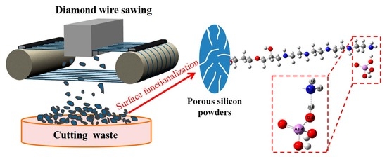
1. Introduction
2. Materials and Methods
2.1. Chemicals and Reagent
2.2. Preparation of Nanoporous Silicon (NPSi)
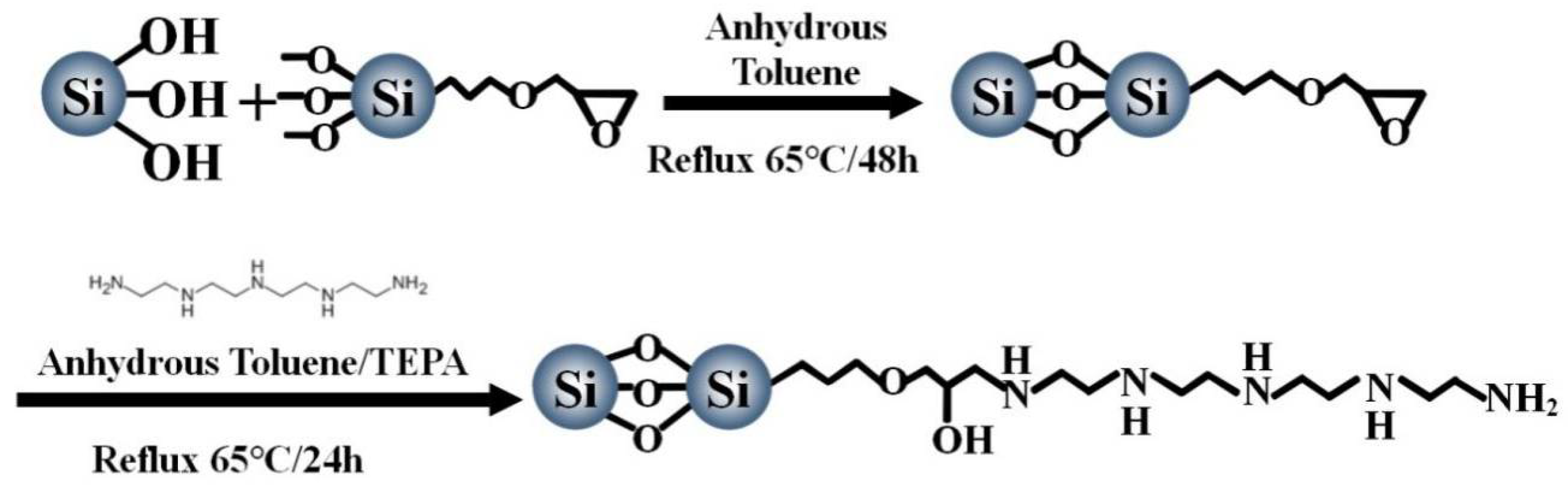
2.3. Synthesis of TEPA-GTS-NPSi
2.4. Characterization of Materials
2.5. Batch Adsorption Studies
3. Results and Discussion
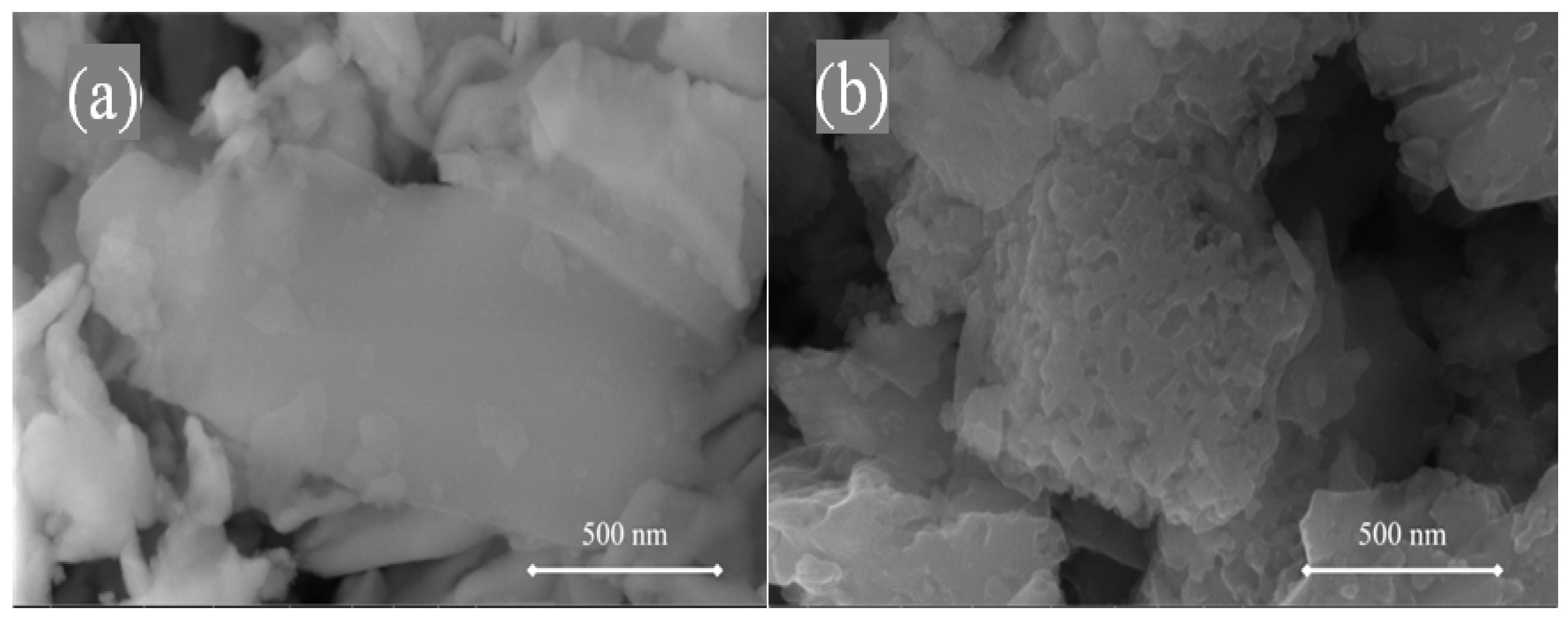
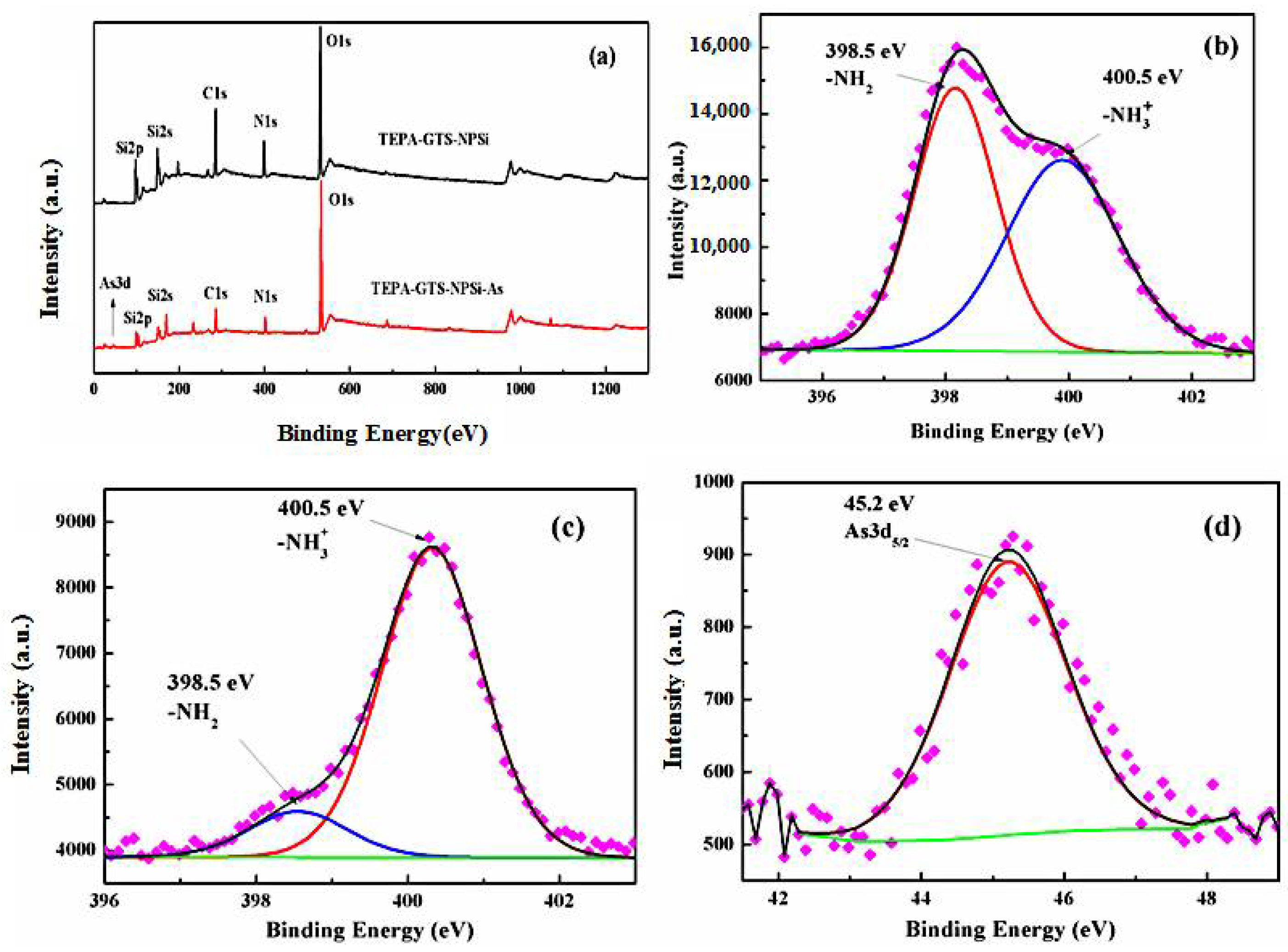
3.1. Characterization of the Amino-Functionalized Nanoporous Silicon
3.2. Adsorption Performance
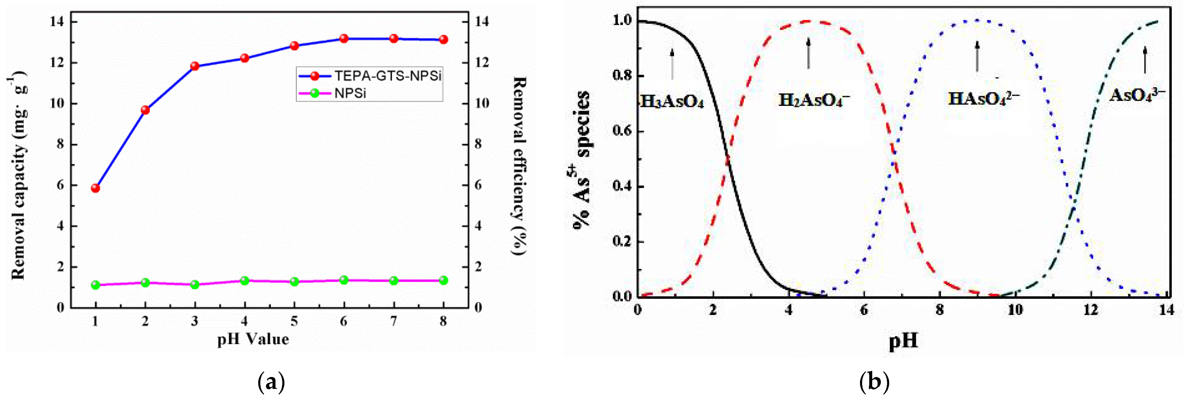
3.2.1. Effect of pH on As(V) Adsorption
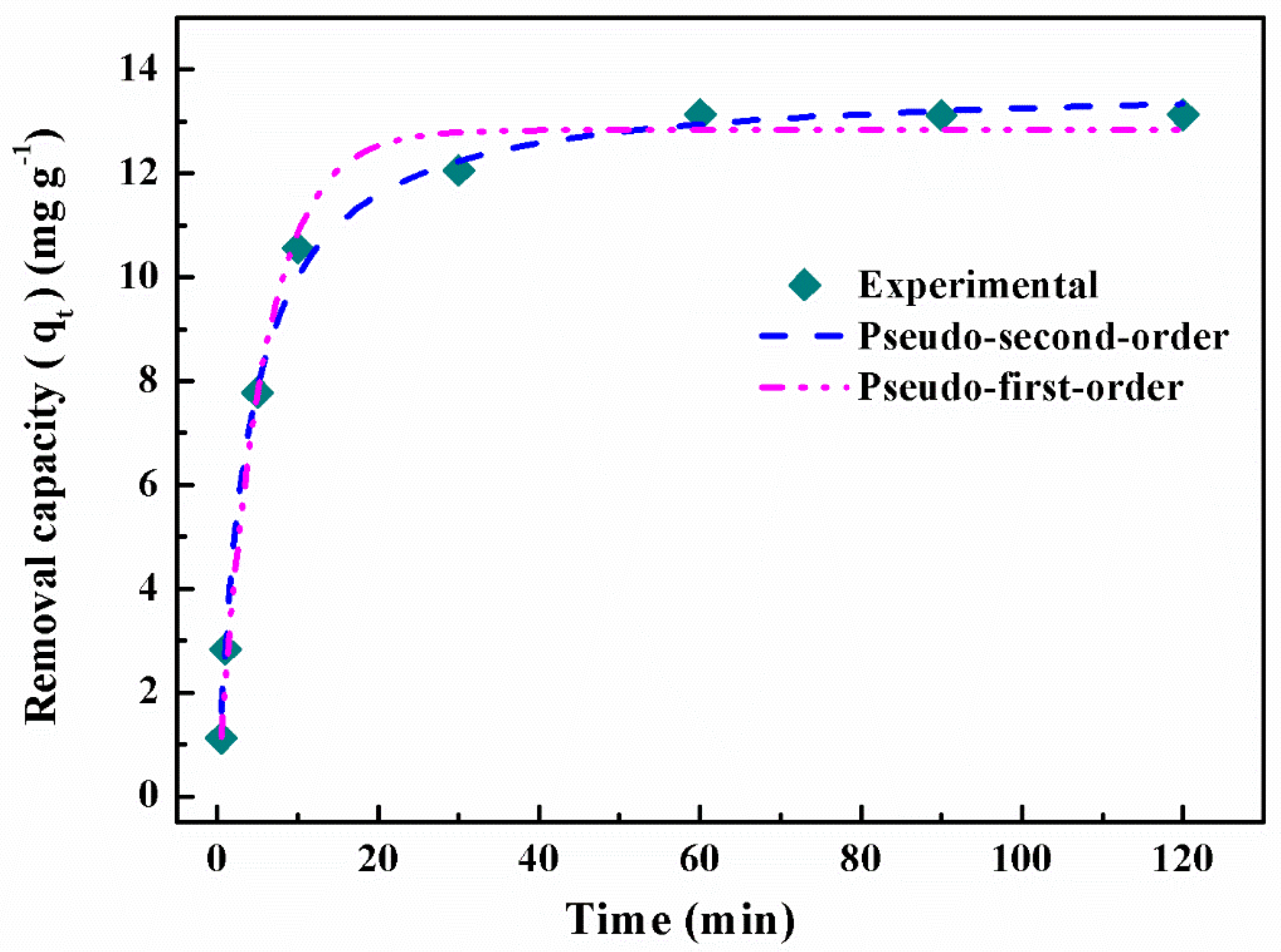
3.2.2. Effect of the Contact Time and Adsorption Kinetics
3.2.3. Adsorption Mechanism
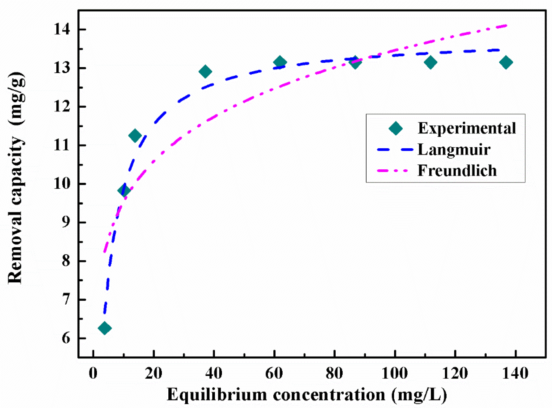
3.2.4. Effect of Initial As(V) Concentration and Adsorption Isotherms
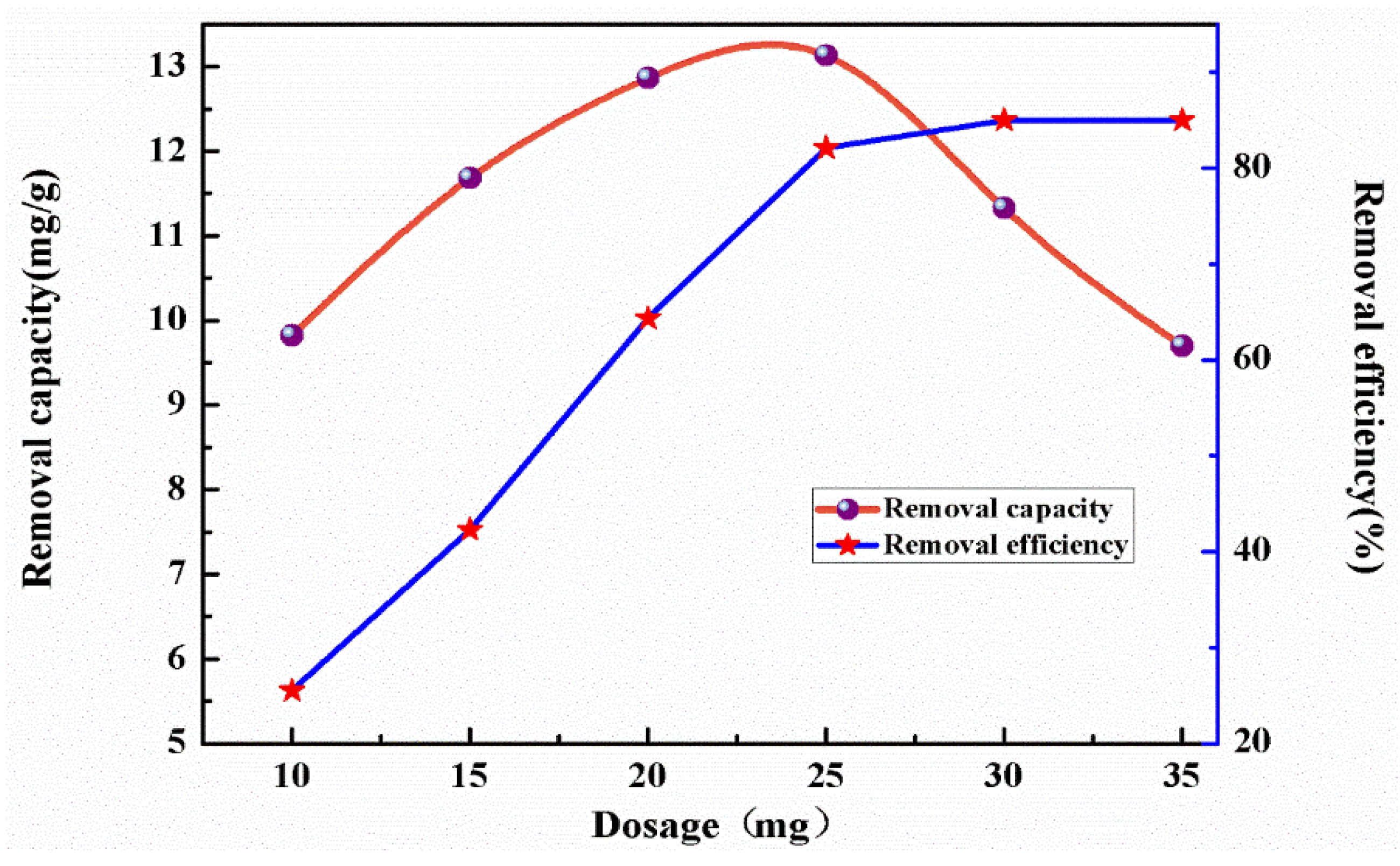
3.2.5. Effect of Dosage and Adsorption Limit
3.2.6. Regeneration and Reuse of TEPA-GTS-NPSi
3.2.7. Practical Application of Industrial Wastewater
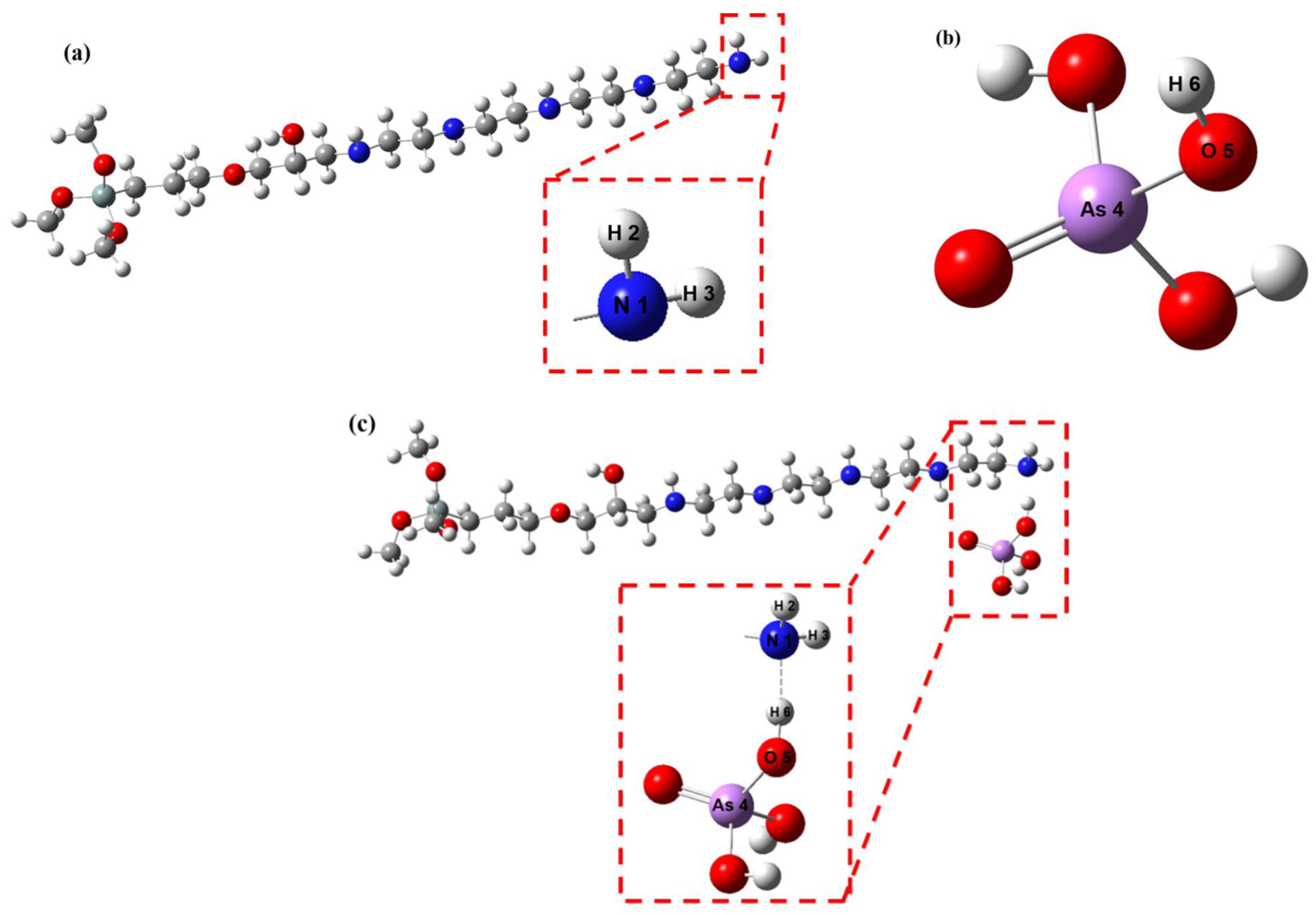
3.2.8. DFT Analysis
4. Conclusions
Supplementary Materials
Author Contributions
Funding
Institutional Review Board Statement
Informed Consent Statement
Data Availability Statement
Conflicts of Interest
References
- Srinivasan, S.; Kottam, V.K.R. Solar photovoltaic module production: Environmental footprint, management horizons and investor goodwill. Renew. Sustain. Energy Rev. 2018, 81, 874–882. [Google Scholar] [CrossRef]
- Sreejith, K.; Sharma, A.K.; Kumbhar, S.; Kottantharayil, A.; Basu, P.K. An additive-free non-metallic energy efficient industrial texturization process for diamond wire sawn multicrystalline silicon wafers. Sol. Energy 2019, 184, 162–172. [Google Scholar] [CrossRef]
- Yang, Z.; Chen, X.; Li, S.; Ma, W.; Li, Y.; He, Z.; Hu, H.; Wang, T. Effective removal of Cd (II) from aqueous solution based on multifunctional nanoporous silicon derived from solar kerf loss waste. J. Hazard. Mater. 2019, 385, 121522. [Google Scholar] [CrossRef]
- Yang, S.; Wei, K.; Ma, W.; Xie, K.; Wu, J.; Lei, Y. Kinetic mechanism of aluminum removal from diamond wire saw powder in HCl solution. J. Hazard. Mater. 2019, 368, 1–9. [Google Scholar] [CrossRef]
- Yang, S.; Ma, W.; Wei, K.; Xie, K.; Wang, Z. Thermodynamic analysis and experimental verification for silicon recovery from the diamond wire saw silicon powder by vacuum carbothermal reduction. Sep. Purif. Technol. 2019, 228, 115754. [Google Scholar] [CrossRef]
- Yang, S.; Wan, X.; Wei, K.; Ma, W.; Wang, Z. Dissolution and mineralization behavior of metallic impurity content in diamond wire saw silicon powder during acid leaching. J. Clean. Prod. 2020, 248, 119256. [Google Scholar] [CrossRef]
- Wang, Y.-Y.; Chai, L.-Y.; Yang, W.-C. Arsenic Distribution and Pollution Characteristics in Arsenic Pollution Control in Nonferrous Metallurgy; Springer: Berlin/Heideberg, Germany, 2019; pp. 1–15. [Google Scholar]
- Ganesan, N.; Bambino, K.; Boffetta, P.; Labgaa, I. Exploring the potential carcinogenic role of arsenic in gallbladder cancer. Eur. J. Cancer Prev. 2020, 29, 100–109. [Google Scholar] [CrossRef] [PubMed]
- Aredes, S.; Klein, B.; Pawlik, M. The removal of arsenic from water using natural iron oxide minerals. J. Clean. Prod. 2013, 60, 71–76. [Google Scholar] [CrossRef]
- Ahoranta, S.H.; Kokko, M.E.; Papirio, S.; Özkaya, B.; Puhakka, J.A. Arsenic removal from acidic solutions with biogenic ferric precipitates. J. Hazard. Mater. 2016, 306, 124–132. [Google Scholar] [CrossRef]
- Kabay, N.; Ipek, İ.Y.; Yilmaz, P.K.; Samatya, S.; Bryjak, M.; Yoshizuka, K.; Tuncel, S.A.; Yükel, Ü.; Yüksel, M. Removal of Boron and Arsenic from Geothermal Water by Ion-Exchange in Geothermal Water Management; CRC Press: Boca Raton, FL, USA, 2018; pp. 135–155. [Google Scholar]
- Mohora, E.; Rončević, S.; Agbaba, J.; Zrnić, K.; Tubić, A.; Adžemović, M.; Dalmacija, B. Effects of combined Fe-Al electrodes and groundwater temperature on arsenic removal by electrocoagulation. Environ. Prot. Eng. 2019, 45. [Google Scholar] [CrossRef]
- Kumar, M.; RaoT, S.; Isloor, A.M.; Ibrahim, G.S.; Ismail, N.; Ismail, A.F.; Asiri, A.M. Use of cellulose acetate/polyphenylsulfone derivatives to fabricate ultrafiltration hollow fiber membranes for the removal of arsenic from drinking water. Int. J. Biol. Macromol. 2019, 129, 715–727. [Google Scholar] [CrossRef]
- Elcik, H.; Celik, S.O.; Cakmakci, M.; Özkaya, B. Performance of nanofiltration and reverse osmosis membranes for arsenic removal from drinking water. Desalination Water Treat. 2016, 57, 20422–20429. [Google Scholar] [CrossRef]
- Kazi, T.G.; Brahman, K.D.; Baig, J.A.; Afridi, H.I. A new efficient indigenous material for simultaneous removal of fluoride and inorganic arsenic species from groundwater. J. Hazard. Mater. 2018, 357, 159–167. [Google Scholar] [CrossRef]
- Hao, L.; Zheng, T.; Jiang, J.; Zhang, G.; Wang, P. Removal of As (III) and As (V) from water using iron doped amino functionalized sawdust: Characterization, adsorptive performance and UF membrane separation. Chem. Eng. J. 2016, 292, 163–173. [Google Scholar] [CrossRef]
- Karanac, M.; Đolić, M.; Veličković, Z.; Kapidžić, A.; Ivanovski, V.; Mitrić, M.; Marinković, A. Efficient multistep arsenate removal onto magnetite modified fly ash. J. Environ. Manag. 2018, 224, 263–276. [Google Scholar] [CrossRef] [PubMed]
- Vojoudi, H.; Badiei, A.; Bahar, S.; Ziarani, G.M.; Faridbod, F.; Ganjali, M.R. Post-modification of nanoporous silica type SBA-15 by bis (3-triethoxysilylpropyl) tetrasulfide as an efficient adsorbent for arsenic removal. Powder Technol. 2017, 319, 271–278. [Google Scholar] [CrossRef]
- Sherlala, A.; Raman, A.; Bello, M. Synthesis and characterization of magnetic graphene oxide for arsenic removal from aqueous solution. Environ. Technol. 2019, 40, 1508–1516. [Google Scholar] [CrossRef] [PubMed]
- Kim, D.; Zuidema, J.M.; Kang, J.; Pan, Y.; Wu, L.; Warther, D.; Arkles, B.; Sailor, M.J. Facile surface modification of hydroxylated silicon nanostructures using heterocyclic silanes. J. Am. Chem. Soc. 2016, 138, 15106–15109. [Google Scholar] [CrossRef]
- Xi, F.; Cui, H.; Zhang, Z.; Yang, Z.; Li, S.; Ma, W.; Wei, K.; Chen, Z.; Lei, Y.; Wu, J. Novel and efficient purification of silicon through ultrasonic-Cu catalyzed chemical leaching. Ultrason. Sonochem. 2019, 56, 474–480. [Google Scholar] [CrossRef] [PubMed]
- Xi, F.; Li, S.; Ma, W.; He, Z.; Geng, C.; Chen, Z.; Wei, K.; Lei, Y.; Xie, K. Simple and high-effective purification of metallurgical-grade silicon through Cu-catalyzed chemical leaching. JOM 2018, 70, 2041–2047. [Google Scholar] [CrossRef]
- Jarzabek, D.M.; Siewert, D.; Fabianowski, W.; Schift, H.; Rymuza, Z.; Jung, T. Influence of alkali ions on tribological properties of silicon surface. Tribol. Lett. 2015, 60, 1–8. [Google Scholar] [CrossRef] [Green Version]
- Wayner, D.D.M.; Wolkow, R.A. Organic modification of hydrogen terminated silicon surfaces. J. Chem. Soc. Perkin Trans. 2 2002, 2, 23–34. [Google Scholar]
- Zhang, D.; Gan, Y. Recent progress on critical cleaning of sapphire single-crystal substrates: A mini-review. Recent Pat. Chem. Eng. 2013, 6, 161–166. [Google Scholar] [CrossRef]
- Gupta, V.; Moradi, O.; Tyagi, I.; Agarwal, S.; Sadegh, H.; Shahryari-Ghoshekandi, R.; Makhlouf, A.; Goodarzi, M.; Garshasbi, A. Study on the removal of heavy metal ions from industry waste by carbon nanotubes: Effect of the surface modification: A review. Crit. Rev. Environ. Sci. Technol. 2016, 46, 93–118. [Google Scholar] [CrossRef]
- del Hierro, I.; Pérez, Y.; Fajardo, M. Supported choline hydroxide (ionic liquid) on mesoporous silica as heterogeneous catalyst for Knoevenagel condensation reactions. Microporous Mesoporous Mater. 2018, 263, 173–180. [Google Scholar] [CrossRef]
- Pan, Q.; Wang, B.; Chen, Z.; Zhao, J. Reinforcement and antioxidation effects of antioxidant functionalized silica in styrene–butadiene rubber. Mater. Des. 2013, 50, 558–565. [Google Scholar] [CrossRef]
- Fan, H.-T.; Sun, T.; Xu, H.-B.; Yang, Y.-J.; Tang, Q.; Sun, Y. Removal of arsenic (V) from aqueous solutions using 3-[2-(2-aminoethylamino) ethylamino] propyl-trimethoxysilane functionalized silica gel adsorbent. Desalination 2011, 278, 238–243. [Google Scholar] [CrossRef]
- Behjati, M.; Baghdadi, M.; Karbassi, A. Removal of mercury from contaminated saline wasters using dithiocarbamate functionalized-magnetic nanocomposite. J. Environ. Manag. 2018, 213, 66–78. [Google Scholar] [CrossRef]
- Xiong, C.; Wang, S.; Zhang, L.; Li, Y.; Srinivasakannan, C.; Peng, J. Preparation and application of phosphinic acid functionalized nanosilica for the effective removal of mercury (II) in aqueous solutions. J. Sol. Gel. Sci. Technol. 2018, 87, 442–454. [Google Scholar] [CrossRef]
- Ananpattarachai, J.; Kajitvichyanukul, P. Enhancement of chromium removal efficiency on adsorption and photocatalytic reduction using a bio-catalyst, titania-impregnated chitosan/xylan hybrid film. J. Clean. Prod. 2016, 130, 126–136. [Google Scholar] [CrossRef]
- Wu, L.-K.; Wu, H.; Zhang, H.-B.; Cao, H.-Z.; Hou, G.-Y.; Tang, Y.-P.; Zheng, G.-Q. Graphene oxide/CuFe2O4 foam as an efficient absorbent for arsenic removal from water. Chem. Eng. J. 2018, 334, 1808–1819. [Google Scholar] [CrossRef]
- Lee, J.; Kim, J.-H.; Choi, K.; Kim, H.-G.; Park, J.-A.; Cho, S.-H.; Hong, S.W.; Lee, J.-H.; Lee, J.H.; Lee, S. Investigation of the mechanism of chromium removal in (3-aminopropyl) trimethoxysilane functionalized mesoporous silica. Sci. Rep. 2018, 8, 1–11. [Google Scholar] [CrossRef]
- Liu, C.-H.; Chuang, Y.-H.; Chen, T.-Y.; Tian, Y.; Li, H.; Wang, M.-K.; Zhang, W. Mechanism of arsenic adsorption on magnetite nanoparticles from water: Thermodynamic and spectroscopic studies. Environ. Sci. Technol. 2015, 49, 7726–7734. [Google Scholar] [CrossRef]
- Setyono, D.; Valiyaveettil, S. Chemically modified sawdust as renewable adsorbent for arsenic removal from water. ACS Sustain. Chem. Eng. 2014, 2, 2722–2729. [Google Scholar] [CrossRef]
- Zhu, N.; Yan, T.; Qiao, J.; Cao, H. Adsorption of arsenic, phosphorus and chromium by bismuth impregnated biochar: Adsorption mechanism and depleted adsorbent utilization. Chemosphere 2016, 164, 32–40. [Google Scholar] [CrossRef]
- Shokri, E.; Yegani, R.; Akbarzadeh, A. Novel adsorptive mixed matrix membranes by embedding modified montmorillonite with arginine amino acid into polysulfones for As (V) removal. Appl. Clay Sci. 2017, 144, 141–149. [Google Scholar] [CrossRef]
- Li, L.; Wu, C.; Wang, Z.; Zhao, L.; Li, Z.; Sun, C.; Sun, T. Density functional theory (DFT) and natural bond orbital (NBO) study of vibrational spectra and intramolecular hydrogen bond interaction of l-ornithine–l-aspartate. Spectrochim. Acta Part A Mol. Biomol. Spectrosc. 2015, 136, 338–346. [Google Scholar] [CrossRef]
- Muthuraja, P.; Dhandapani, M. Quantum chemical calculations, physico-chemical characterizations and crystal structural analysis of a new organic-hydrogen bond networked crystal, 2-aminothiazolium benzilate. J. Mol. Struct. 2019, 1197, 19–33. [Google Scholar]


| Pseudo-First-Order Model | Pseudo-Second-Order Model |
|---|---|
| k1 = 0.18633 min−1 | k2 = 0.01953 g∙mg−1∙min−1 |
| R2 = 0.9909 | R2 = 0.9952 |
| Adsorbent | Adsorption Capacity (mg/g) | Reference |
|---|---|---|
| Magnetite | 17.2 | [35] |
| ZrO2-sawdust | 12 | [36] |
| Organic biochar | 16.2 | [37] |
| Mt-Arg | 16.5 | [38] |
| NPSi | 13.2 | This work |
| Langmuir Adsorption Isotherm | Freundlich Adsorption Isotherm |
|---|---|
| qmax = 13.8754 mg∙g−1 | KF = 6.7737 |
| KL = 0.2483 L∙mg−1 | n = 6.7050 |
| R2 = 0.9782 | R2 = 0.7613 |
| As | Cu | Zn | |
|---|---|---|---|
| Before (mg/L) | 297.6 | 28.28 | 17.66 |
| After (mg/L) | 272.86 | 26.36 | 16.84 |
| Adsorption capacity (mg/g) | 12.37 | 0.96 | 0.41 |
| TEPA-GTS | As-TEPA-GTS | ||
|---|---|---|---|
| N 1–H 2 | 1.01573 | N 1–H 2 | 1.01645 |
| N 1–H 3 | 1.01429 | N 1–H 3 | 1.01570 |
| H3ASO4 | N 1–H 6 | 1.64556 | |
| As 4–O 5 | 1.74407 | As 4–O 5 | 1.70956 |
| O 5–H 6 | 0.96413 | O 5–H 6 | 1.02435 |
| TEPA-GTS and H3ASO4 | As-TEPA-GTS | ||
|---|---|---|---|
| N 1 | −0.83850 | N 1 | −0.85379 |
| H 2 | 0.33584 | H 2 | 0.36266 |
| H 3 | 0.34372 | H 3 | 0.36837 |
| As 4 | 2.72387 | As 4 | 2.74799 |
| O 5 | −1.03976 | O 5 | −1.09851 |
| H 6 | 0.49508 | H 6 | 0.50843 |
Publisher’s Note: MDPI stays neutral with regard to jurisdictional claims in published maps and institutional affiliations. |
© 2021 by the authors. Licensee MDPI, Basel, Switzerland. This article is an open access article distributed under the terms and conditions of the Creative Commons Attribution (CC BY) license (https://creativecommons.org/licenses/by/4.0/).
Share and Cite
Fu, K.; Li, Y.; Chen, X.; Ma, W.; Yang, Z.; Wang, T.; Liu, J.; Ma, Z.; Chen, R.; Chen, X.; et al. Removal of As(V) Based on Amino-Group Surface-Functionalized Porous Silicon Derived from Photovoltaic Silicon Cutting Powder. Coatings 2021, 11, 850. https://doi.org/10.3390/coatings11070850
Fu K, Li Y, Chen X, Ma W, Yang Z, Wang T, Liu J, Ma Z, Chen R, Chen X, et al. Removal of As(V) Based on Amino-Group Surface-Functionalized Porous Silicon Derived from Photovoltaic Silicon Cutting Powder. Coatings. 2021; 11(7):850. https://doi.org/10.3390/coatings11070850
Chicago/Turabian StyleFu, Kaixin, Yi Li, Xiumin Chen, Wenhui Ma, Ziheng Yang, Tong Wang, Jiasen Liu, Zhuang Ma, Ran Chen, Xiuhua Chen, and et al. 2021. "Removal of As(V) Based on Amino-Group Surface-Functionalized Porous Silicon Derived from Photovoltaic Silicon Cutting Powder" Coatings 11, no. 7: 850. https://doi.org/10.3390/coatings11070850