Article

Multi-Damage Identification of Multi-Span Bridges Based on Influence Lines

School of Civil and Transportation Engineering, Beijing University of Engineering and Architecture, Beijing 102616, China
*
Author to whom correspondence should be addressed.
Coatings 2021, 11(8), 905; https://doi.org/10.3390/coatings11080905
Submission received: 16 June 2021 / Revised: 19 July 2021 / Accepted: 23 July 2021 / Published: 28 July 2021
(This article belongs to the Special Issue Corrosion and Degradation of Materials)

Abstract

:
The framework security of a bridge is essential as a critical component of traffic engineering. Even though the bridge structure is damaged to various degrees due to various reasons, the bridge will be wrecked when the damage reaches a particular level, suggesting a negative influence on people’s lives. Based on the current situation and existing problems of structural damage identification of bridges, a structural damage identification technology of continuous beam bridges based on deflection influence lines is proposed in this paper in order to keep track of and always detect broken bridge elements, thereby extending the bridge’s service life and reducing the risk of catastrophic accidents. The line function expression of deflection impact on a multi-span continuous beam bridge was first obtained using Graphic Multiplication theory. From the theoretical level, the influence line function of the continuous beam bridge without extensive damage was computed, and a graph was generated. The photographs of the DIL as well as the first and second derivatives, the deflection influence line distinction and its first and second derivatives, and the DIL distinction and its first and second derivatives of a continuous beam bridge in a single position and multi-position destruction were fitted in this paper. Finally, after comparing multiple work conditions and multiple measuring points, it was found that the first derivative of deflection influence line difference had the best damage identification effect. The design was completed and tested, which had verified the feasibility of this theory.

1. Introduction

The economy of any nation is heavily reliant on transportation infrastructure. It is critical to ensure that this infrastructure has dependable mobility and serviceability. Bridges are an important element of this infrastructure, and they need to be inspected and maintained regularly to stay in good working order [1]. Appropriate maintenance helps to prevent costly bridge repair and replacement by extending the structural life. The timing of maintenance activity, the activity itself, and the scope of such an activity are all important components of effective maintenance programs. Bridge maintenance is an important part of the operations necessary to maintain bridge infrastructure, maintain essential safe operational levels with minimal disruptions, and cost-effectively extend the life of structures [2]. As a result, bridge maintenance is an essential component of any bridge management strategy. It is widely acknowledged that appropriate maintenance operations will extend the bridge’s operational life [1].
As a vital transport system, a bridge has a long service life, at a minimum of more than 50 years, and the life span is continuously moving on [3]. Due to comprehensive actions of numerous aspects, for example environs, raw ingredients, and lassitude possessions, the bridge’s functional structure deteriorates due to such aspects and catastrophic accidents occur when it is more serious [4,5,6]. By 2016, a total of 830,000 highway bridges were found in China, so it urgently needed to identify the damages of domestic bridges with firm and precise fundamental impairments credentials [7]. Other countries are also under the same conditions [8,9,10]. There are about 690,000 bridges in the United States, more than 50% of which have been used for a minimum of 50 years [11,12]. Simply, fast and precise operational detection methods could resolve this unmet problem of bridge detection [13,14,15,16].
To analyze and evaluate the bridge’s deterioration detection, Kou Xiaona first practically used the effectual deflection contour (comprising its first derivative and second derivative) to detect deteriorations in the structure [17]. She functionalized the theory of mechanics to the numerical analysis of the purely maintained beam model of the reinforced concrete, and justification was made to achieve the deflection influence line (DIL) of the simply supported beam and its first and second derivatives. Afterwards, she performed a finite element modeling analysis by ANSYS. Finally, through the experimental verification, she learned that the DIL could detect the presence of damage and the severity of the damage. Liu Yunshuai selected the deflection difference influence line (DDIL) as a foundation of destruction identification [18]. He assumed the simply supported beam for illustration, the derivatization of the analytical formula for the deflection difference influence line previously, and, later, single-point destruction of the simply supported beam, and at that moment additionally resolved the curvature of the influence line (IL). In addition, he devised a symmetrical loading strategy to remove the finite element model’s inaccuracy. The deflection difference influences line curvature, and it is an excellent identification index and is far more vulnerable to damage identification. Jia Yaping recognized the index of structural damage identification of the continuous beam bridge based on DIL: DDIL, the first and the second derivative of DDIL, and the second derivative of DIL [19]. Formerly, an aluminum alloy plate with a three-span simulated coupling beam was utilized to clarify that the four indexes can recognize if there any destruction and the site of destruction. In the current study, based on DIL and calculation basis theory, the calculation method of DIL of the multi-span continuous beam was proposed by theoretical derivation and experimental verification through MIDAS/Civil modeling. A relevant study was performed on whether there is any damage to the DIL (and its first and second derivatives), the damage position, and damage degree, and the damage location and the damage degree is deduced with the IL (and its first and second derivatives). A structural damage identification (SDI) system based on the function of the DIL (and its first and second derivatives) was obtained, and the theory was confirmed by a simulation test of a plexiglass plate. Besides the structural elements, previous studies showed that non-structural elements also play a significant role in bridge deflection. For instance, previous authors demonstrated that the non-structural elements, including the pedestrian sidewalk and overlay of joint granite block, could significantly cause deflection in the historical Boco bridge [20].

2. Numerical Methods and Materials

Here we explained the theoretical deflection influence line equations of the continuous bean under damage.

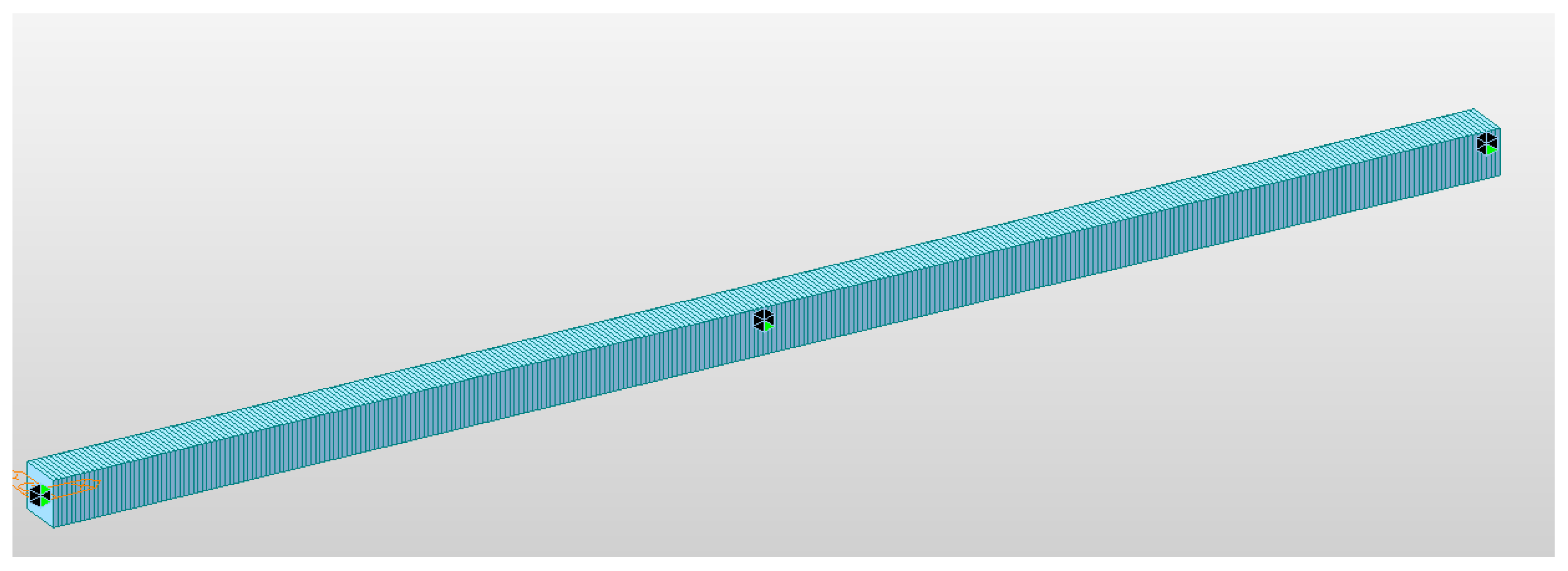
2.1. Relevant Parameters of Calculation Model

The two-span continuous beam (as publicized in Figure 1) was taken as the theoretical study subject, the span was 160 cm, the left end support was immovable hinge support, and the other supports are sliding or movable hinge supports. The DIL equations of the model under the condition of health and damage were deduced.

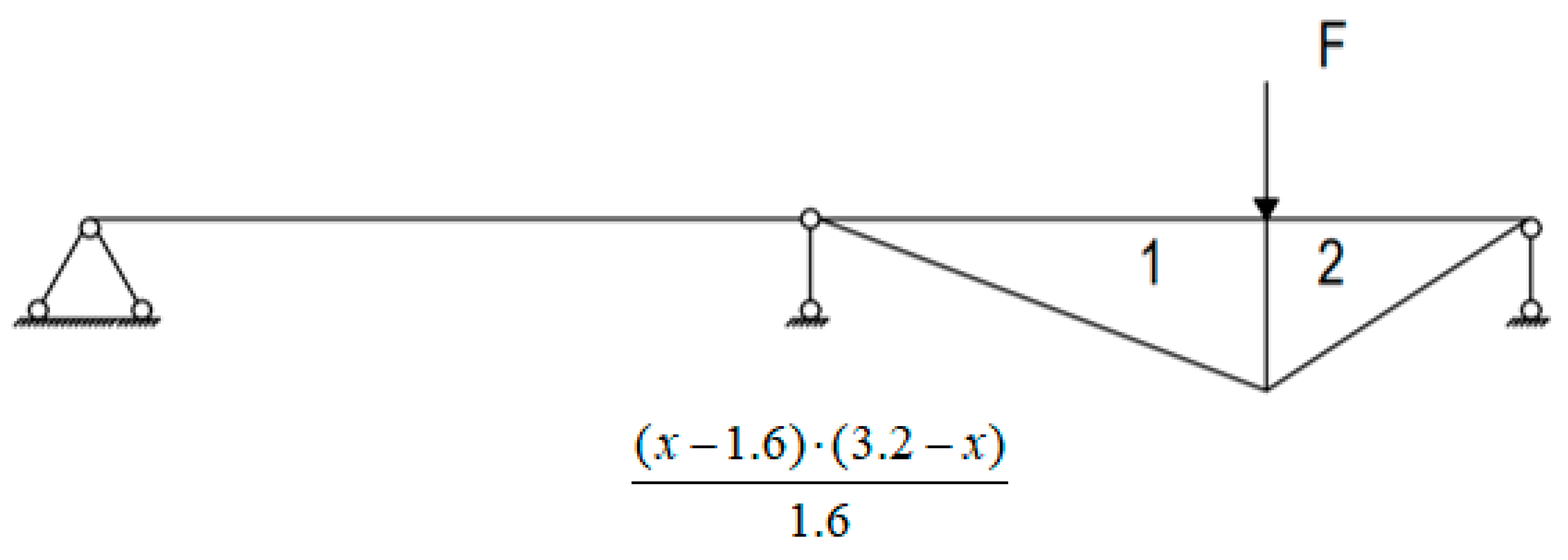
2.2. Deflection Influences Line Equation of Structure without Loss

Next, captivating the midspan section of the second span of the laboratory model as a specimen, the theoretical derivation of non-destructive deflection IL of the structure of the continuous beam bridge was carried out. As shown in Figure 2, for two equal-span continuous beams, the calculated section of the influence line was in the midspan of the second span, and one unit force F = 1 was acting on the structure, F was x far from the t left side of the structure.
The fulcrum on the left side of the Figure M was considered as the coordinate origin, and the image equation of M is:
{ y = 1.5 16 x                                                         x 1.6   y = 0.59375 x + 1.1                             1.6 < x 2.4 y = 0.40625 x 1.3                                 2.4 < x 3.2
When the unit load acts on the 1st span, the bending moment diagram of the basic structure is shown in Figure 3.
The area of area 1 is: S 1 = x 2 ( 1.6 x ) 3.2 .
The gravity is:
2 3 x
The area of Area 2 is:
S 2 = x ( 1.6 x ) 2 3.2 .
The gravity is:
2 x 3 + 1.6 3
When the unit load acts on the 2nd span, the bending moment diagram of the basic mechanism is shown in Figure 4.
The area of Area 1 is:
S 1 = ( x 1.6 ) 2 ( 3.2 x ) 3.2 .
The gravity is:
2 3 x + 1.6 3
The area of Area 2 is:
S 2 = ( x 1.6 ) ( 3.2 x ) 2 3.2 .
The gravity is:
2 x 3 + 3.2 3
The following is the multiplication of graphs.
When the unit load (UL) acts on the 1st span, the center of gravity (Cg) of Area 1 and Area 2 is in the first equation. Where 0 x 1.6 , the deflection is:
Δ = 1 E I [ x 2 ( 1.6 x ) 3.2 1.5 16 2 3 x + x ( 1.6 x ) 2 3.2 1.5 16 ( 2 3 x + 1.6 3 ) ]
When the UL acts on the 2nd span, the Cg position of Area 1 and Area 2 is discussed again.
(1)
When the Cg is all in the 2nd equation: y = 0.59375 x + 1.1
It shall meet:
{ 1.6 < 2 3 x + 1.6 3 2.4 1.6 < 2 3 x + 3.2 3 2.4
Then, 1.6 < x 2
The deflection is:
Δ = 1 E I [ ( x 1.6 ) 2 ( 3.2 x ) 3.2 ( 1.1 0.59375 ( 2 3 x + 1.6 3 ) ) + ( x 1.6 ) ( 3.2 x ) 2 3.2 ( 1.1 0.59375 ( 2 3 x + 3.2 3 ) ) ]
(2)
When the Cg of Area 1 is in the 2nd equation: y = 0.59375 x + 1.1 ;
When the Cg of Area 2 is in the 3rd equation: y = 0.40625 x 1.3 , then
{ 1.6 < 2 3 x + 1.6 3 2.4 2.4 < 2 3 x + 3.2 3 3.2
i.e., 2 < x 2 . 8
The deflection is:
Δ = 1 E I [ ( x 1.6 ) 2 ( 3.2 x ) 3.2 ( 11 0.59375 ( 2 3 x + 1.6 3 ) ) + ( x 1.6 ) ( 3.2 x ) 2 3.2 ( 0.40625 ( 2 3 x + 3.2 3 ) 1.3 ) ]
(3)
When the Cg of Area 1 and Area 2 is in the 3rd equation:
y = 0.40625 x 1.3       2.8 < x 3.2 .
The deflection is:
Δ = 1 E I [ ( x 1.6 ) 2 ( 3.2 x ) 3.2 ( 0.40625 ( 2 3 x + 1.6 3 ) 1.3 ) + ( x 1.6 ) ( 3.2 x ) 2 3.2 ( 0.40625 ( 2 3 x + 3 . 2 3 ) 1.3 ) ]
Figure 5 shows the results of drawing the function image of the theoretical deflection effect line using MATLAB. When calculating the DIL of the damaged continuous beam, the bending stiffness of the deteriorated section is set E I Reduced to E I . The calculation process is the same; when the damage section is involved, the graph multiplication is used separately. The deflection influence line is deduced theoretically and the following rules are obtained:
(1) The location x of the moving load has a cubic connection with the DIL in any part of the continuous beam, and the DIL is continuous throughout the continuous beam structure.
(2) The bending stiffness E I changes significantly impact the DIL of a continuous beam, and the difference in the DIL will directly represent bending stiffness variations.

3. Study on Deflection Influence Line Identification of Continuous Beam with Multiple Damage under Ideal Condition

Using the continuous two-span beam as the opposite direction, Midas Civil was utilized to analyze the DIL of continuous beam bridge under normal condition and damage conditions of important portions. The determining points were respectively organized at 25/100 point of the 1st span and the 2nd span, and at 75/100 point in the middle of the span. The deflection data of key positions were collected and processed (25/100 of the 1st span, the first span and 75/100 of the 1st span) to evidence the precision of the theory and applied use. First, the ideal model simulation was carried out (that is, a single point dynamic load was defined to act on the continuous beam), and the continuous beam was shown in Figure 6. The span of the two spans was 1.6 m, and the local structure was shown in the figure. The detailed research was divided into single location damage identification and multi-location destruction identification.

3.1. Establishment of Multiple Damage Model

As displayed in Figure 6, the idealized model of the continuous beam structure was that the UL acted on the central line of the beam. Locating the structure type to the X-Z plane could shorten the design process. To make the model easier to understand, C50 concrete under the JTG3362-18(RC) code was directly selected as the material, including the elastic modulus of concrete E = 3.45 × 10 4   k N / m m 2 , Poisson’s ratio μ = 0.2 , and the coefficient of linear expansion α = 1 × 10 5   1 / ° C . Two sections were added and named “normal” and “damage”, respectively. The solid web rectangular section was selected, and the section size was 100 mm ∗ 100 mm. The numerical model had 321 nodes, 320 elements, and boundary conditions and a schematic diagram are evaluated.
The bending stiffness of normal material is EI, and that of damaged material is EI* α ( α is the reduction factor). In the Midas Civil model, only the damaged part changes   I y y to simulate the loss.
The boundary conditions were applied at Nodes 1, 161, and 321, respectively. The fixed hinge bearing was used at Node 1 to limit the displacement in x and z directions, and the sliding hinge bearing is used at nodes 161 and 321 to limit the displacement in z direction.
The loads were organized once the boundary conditions were specified. Only one lane was set up to make the computation easier. Because the track surface was not involved, only the lane line had to be set up. After setting the load, i.e., moving the load, observe the DIL.
In view of the multi-position damage of continuous beam bridges in practical engineering, 10 kinds of work conditions were simulated. The damage simulation of the key position of the continuous beam was carried out respectively. Because the two-span continuous beam of the test model was symmetrical structure, only half-span damage simulation was carried out.
The damage degree was divided into four grades: 10%, 20%, 30%, and 50%. The specific work conditions are shown in Figure 7 and Figure 8 and Table 1 and Table 2. Each work condition was further subdivided according to the damage degree.

3.2. Multi-Point Destruction Recognition of Deflection Influence Line

Draw the deflection influence line data obtained from work condition 1 (1–5) and work condition 2 (1–5) of the 1st span 1/4 determining point. As shown in Figure 9 and Figure 10, there is no significant difference in the trend and value of the image under different damage locations, so the location of multi-point damage cannot be identified by the deflection influence line.

3.3. Multi-Point Damage Identification Based on 1st Derivative of Deflection Influence Line

Under condition 1 (1-5) and condition 2 (1-5), the 1st derivative of deflection influence line obtained from 1/4 determining point of the first span is shown in Figure 11 and Figure 12. It was found that the destruction site could not be recognized by image.

3.4. Multi-Point Damage Identification Based on the 2nd Derivative of Deflection Influence Line

As shown in the figures, in the case of multi-point damage of continuous beam bridge, the deflection sensor was used to collect data and process the 2nd derivative of DIL. According to the rule of the 2nd derivative of DIL in single-point damage identification, the image was analyzed. On the basic line, the position where the large mutation and deviation occur was the damage location. Compared with Figure 13 and Figure 14, it was found that this method could also reflect the damage location well when there was only one measuring point. Compared with Figure 14 and Figure 15, it was found that the effect of different measuring points on structural damage identification was the same under the same work condition.
At the same time, it was found that when the damage location coincides with the observation point, the observed effect was greatly weakened. Because the quadratic function of the DIL of the continuous beam structure was linear, the peak value appeared at the measuring point and the upper fulcrum of the beam. It was difficult to observe when the deviation position coincides with the peak value.

3.5. Multi-Point Damage Identification Based on Deflection Influence Line Difference

Under the condition of multi-point damage simulated by work condition 1 and work condition 2, the image of the DIL difference of each measuring point was extracted (as shown in Figure 16, Figure 17 and Figure 18). According to the relationship between the image change and the damage location, it was found that the image had a small peak value in the structural damage section, but it did not have a great impact on the trend of the whole curve. Therefore, it was theoretically feasible to identify the damage location only through the DIL difference image, but the identification process was very difficult. In order to locate the greatest and excellent parameter index of multi-point destruction detection, the 1st derivative of DIL difference was studied.

3.6. Multi-Point Damage Identification Based on 1st Derivative of Deflection Influence Line Difference

Draw the 1st derivative image of DIL difference under multi-point damage of work condition 1 and work condition 2, as shown in Figure 19, Figure 20 and Figure 21. Based on the first derivative of the DIL difference in the case of single-point damage, the position of the image mutation segment was the corresponding position of the damaged segment. The identification results are shown in the figure. The method had obvious characteristics for the damaged section, and could accurately reflect the damage location in different positions and different working conditions. Consequently, the 1st derivative of the DIL difference was a suitable parameter for structural damage identification.
In order to choose the most appropriate settings, the 1st derivative of the deflection influence line difference was derived again to verify the identification effect of the second derivative for multi-point damage of the continuous beam bridge structure.

3.7. Multi-Point Damage Identification Based on the Second Derivative of Deflection Influence Line Difference

Gather and progress the data of each measuring point under work condition 1 and work condition 2, and acquire the second derivative photograph of the DIL difference of each measuring point (as shown in Figure 22, Figure 23 and Figure 24). According to the second derivative identification law of the influence line difference under single-point damage of the continuous beam bridge structure, the location of the image peak was the location of the damage section. However, due to the influence of measurement accuracy, the 2nd derivative image had great fluctuation, so it had high requirements for measuring instruments to use the 2nd derivative of the IL difference as the identification parameter.

4. Laboratory Validation of the Theoretical Model

4.1. Test Plan

The model is shown in Figure 25, and the bridge was simulated with the acrylic plate. The layout of fixed hinge bearing and sliding bearing is shown in Figure 26, and the bridge deck used a trolley with controllable speed as the moving load, as shown in Figure 27. Two stages of loading were designed in the experiment. The first stage loading was an empty car (mass 1 kg), and the second stage loading was car loading with a 1 kg weight (total mass is 2 kg). In order to avoid vehicle bridge coupling, the vehicle speed was set at 0.128 m/s [15]. Based on the theoretical derivation of each working condition, the non-destructive state and 25% damage state are set, and the thickness of the damaged acrylic plate was 75% of the non-destructive state.

4.2. Testing Equipment

SMTN-X pro-multi-point dynamic video measurement was used to monitor the 1/4 1/2 3/4 position of each span (Figure 28), and the DIL of the measuring point was obtained.

4.3. Identification of Damage Location by Deflection Influence Line and Its First and Second Derivatives

Because of the small deflection of the first level loading, the damage location could not be well reflected, so the second level loading was analyzed.
According to the curve obtained in work condition 5 (Figure 29, Figure 30 and Figure 31), the first derivative of DIL could not effectively detect the destruction site, but the second derivative of DIL could effectively identify the specific destruction site. The results were consistent with the data.
According to the curve obtained in case 4 (Figure 32), it could be seen that the second derivative of the deflection difference IL was universal to identify the destruction site, and it could effectively identify the damage location when it was extended to any damage location

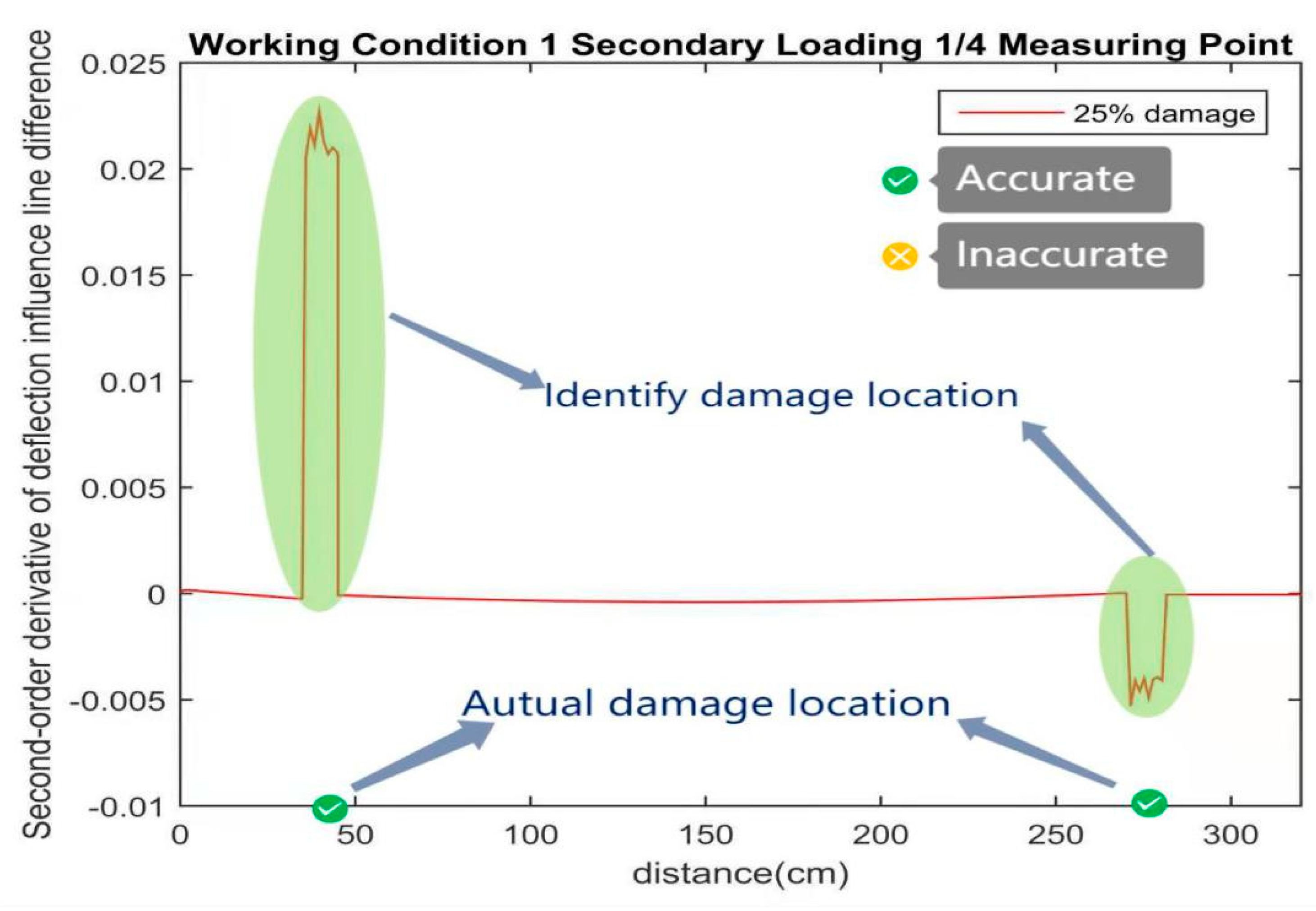
4.4. Identification of Damage Location by Deflection Influence Line Difference and Its First and Second Derivatives

According to the DIL difference and its first-order derivative and second-order derivative obtained from work condition 4 (Figure 33, Figure 34 and Figure 35), the first-order derivative and second-order derivative of DIL could effectively detect the destruction site. However, for the first-order derivative of the DIL difference, the second-order derivative data processing was more difficult, so it was more convenient to identify the damage location by using the first-order derivative of the DIL difference.
According to the curve obtained in work condition 5 (Figure 36 and Figure 37), it could be extended to any case to recognize the damaged location by using the first-order and second-order derivatives of the DIL difference.

5. Discussion

Bridge nondestructive testing procedures can reveal defects in structures without affecting their functionality. When choosing a nondestructive testing approach, accuracy, accessibility, cost, and the repercussions of detection failures or false indications must be considered. There is now many studies being done on how to test bridges quickly and accurately. For many years, researchers have been looking into the idea of utilising vibration methods to identify bridge collapse [21,22,23,24]. Damping ratios are sensitive to structure damage, but they have become quite difficult to calculate. Vibration frequency is frequently used to determine the degree of damage in a structure. It is simple to measure, but it is not sensitive to changes in stiffness. As a result, developing a method of nondestructive testing to detect damage from a global viewpoint is crucial.
Based on the current situation and existing problems of structural damage identification of bridges, a structural damage identification technology of continuous beam bridges based on deflection influence lines is proposed in this paper in order to keep track of and detect broken bridge elements at all times, thereby extending the bridge’s service life and reducing the risk of catastrophic accidents. The line function expression of deflection influence on a multi-span continuous beam bridge was first obtained using the Graphic Multiplication theory. The influence line function of the continuous beam bridge without severe damage was estimated at the theoretical level, and a graph was created. This article included pictures of the DIL and its first and second derivatives, the deflection influence line distinction and its first and second derivatives, and the DIL distinction and its first and second derivatives of a continuous beam bridge in single and multi-position destruction. According to our theoretical model, the position x of the moving load has a cubic link with the DIL in any portion of the continuous beam, according to our theoretical model, and the DIL is continuous throughout the continuous beam structure. Furthermore, changes in bending stiffness have a substantial influence on a continuous beam’s DIL, and the difference in the DIL will directly indicate bending stiffness variations. Finally, it was discovered that the first derivative of deflection influence line difference had the best damage identification impact after evaluating different work circumstances and multiple measuring sites. The design was completed and tested, which had verified the feasibility of this theory. The design was completed and tested, and we validated the experiments. The deflection sensor was utilized to gather data and calculate the second derivative of DIL in the event of multi-point damage of a continuous beam bridge, according to our findings. We examined the picture using the rule of the second derivative of DIL in single-point damage identification. The damage site on the basic line was where the major mutation and deviation occurred. Meanwhile, our analysis shows that the observed effect is substantially diminished when the damage site coincides with the observation point. The peak value appeared at the measuring point and the top fulcrum of the beam because the quadratic function of the DIL of the continuous beam structure was linear. When the deviation location coincided with the peak value, it was difficult to see.
The image of the DIL difference of each measuring point was retrieved under the conditions of multi-point damage simulated by work conditions 1 and 2 (as shown in Figure 16, Figure 17 and Figure 18). We discovered that the image had a small peak value in the structural damage region, but it had limited influence on the overall curve’s trend, based on the link between image change and damage location. As a result, identifying the damage location just using the DIL difference picture was theoretically possible, but the identification procedure was highly challenging. The first derivative of the DIL difference was investigated in order to find the best and most accurate parameter index for multi-point destruction detection.
The first derivative of the deflection influence line difference at 3/4 determination points of the first span under work condition 2 exhibited clear characteristics for the damaged section and could properly indicate the damage site in various locations and working circumstances. As a result, the first derivative of the DIL difference proved to be a useful measure for detecting structural deterioration. The current study suggests that the first derivative of the deflection influence line difference be computed again to validate the identified impact of the second derivative for multi-point damage of continuous beam bridge construction to pick the most appropriate settings.
Flooding occurrences were demonstrated in Italian suburbs by Sasuu et al. whose construction and regulations do not adequately cover maintenance [25]. Several failure scenarios led to this, including vehicle dragging when crossing bridges (A), erosion induced by bridge overtopping, and erosion and floating produced by upward buoyant force from Archimedes’ principle on the bridge slab. The failure mechanisms presented here can be used to identify not just structural failures but also service failures. As a result, for identifying and forecasting multiple damage, especially in multi-span bridges, a suitable model and numerical computation are essential. Crocea et al. tested several techniques and concluded that the suggested procedure is not only appropriate for the intended applications, but also sufficiently “robust” [26]. By further verifying the approach suggested in this work under various experimental settings, it may be able to circumvent such eventualities.
There are several damage identification methods for bridge structures currently available, including intelligent algorithm-based, Bayesian theory-based, time-domain signal processing-based damage identification methods, sparsity information and sparse recovery theory-based, neural network-based damage identification methods, and various model-based methods [27,28,29,30,31,32,33]. These approaches are described conceptually and then proven in actual bridges through tests and experimentation. All of them have benefits and drawbacks; nevertheless, we feel that the first derivative of the DIL divergence is the greatest damage detection indicator, exceeding other parameters in terms of simplicity and accuracy of observation. Damage detection approaches based on displacement influence lines may be successfully utilised to detect and locate damage based on numerical studies and experimental verification. This will allow it to be used in a more suitable and useful way in the real bridge.

6. Conclusions

To sum up, the current study identifies the multi-damage of multi-span bridges based on influence lines. This paper fits the DIL and the first and second derivatives of the continuous beam bridge when the damage occurs at multiple positions, and the difference between the DIL and the first and second derivatives of the image. The photographs of the DIL and the first and second derivatives, the deflection influence line distinction and its first and second derivatives, and the DIL distinction and its first and second derivatives of a continuous beam bridge in a single position and multi-position destruction were fitted in this paper. The ideal identification parameters were determined as the basis of visual tracking systems by evaluating the detection methods and effectiveness under various locations, degrees, and measurement locations. This was the crucial criterion for identifying deterioration in a continuous beam building frame that has been in use, and the deterioration was found. The second derivative of the DIL, the first derivative of the DIL discrepancy, and the second derivative of the DIL distinction were the basic design damage detection indexes. The photographic characteristics were not visible and hard to recognize because there were still mutation spots in the second derivative of the deflection effect line in addition to the site of damage. The second derivative of the deflection effect line differences had to be determined using a high-precision device that was hard to fit, but it may also approximate the damage site. As a result, employing the second derivative of the deflection effect line difference posed a significant challenge to the instrument’s reliability. To summarize, the first derivative of the DIL divergence was the best damage detection indicator, surpassing other parameters in terms of observation ease and accuracy, which will enable this to be more appropriately and beneficially applied to real bridges. We hope that our study will be of great interest for the readers of this journal.

Author Contributions

Conceptualization, Y.Z. and Q.X.; methodology, Y.Z.; software, Y.Z.; validation, Y.Z., Q.X., G.L. and Y.L.; formal analysis, Y.Z., Q.X., G.L. and Y.L.; investigation, Y.Z., Q.X., G.L. and Y.L.; resources, G.L. and Y.L.; writing—original draft preparation, Y.Z.; writing—review and editing, Y.Z. and Y.L.; supervision, Y.L.; project administration, Y.L.; funding acquisition, Y.L. All authors have read and agreed to the published version of the manuscript.

Funding

This research was funded by National College Students’ Innovation and Entrepreneurship Training Project, grant number 202010016018.

Institutional Review Board Statement

Not Applicable.

Informed Consent Statement

Not Applicable.

Acknowledgments

This research was supported by National College Students’ Innovation and Entrepreneurship Training Project (No. 202010016018).

Conflicts of Interest

The authors declare no conflict of interest.

References

  1. Alampalli, S.; Ettouney, M.M.; Agrawal, A.K. Structural health monitoring for bridge maintenance. Bridge Struct. 2005, 1, 345–354. [Google Scholar] [CrossRef]
  2. Fujino, Y.; Siringoringo, D.M.; Ikeda, Y.; Nagayama, T.; Mizutani, T. Research and Implementations of Structural Monitoring for Bridges and Buildings in Japan. Engineering 2019, 5, 1093–1119. [Google Scholar] [CrossRef]
  3. An, Y.; Chatzi, E.; Sim, S.-H.; Laflamme, S.; Blachowski, B.; Ou, J. Recent progress and future trends on damage identification methods for bridge structures. Struct. Control. Health Monit. 2019, 26, e2416. [Google Scholar] [CrossRef]
  4. Zhou, Y.; Di, S.; Xiang, C.; Li, W.; Wang, L. Damage identification in simply supported bridge based on rotational-angle influence lines method. Trans. Tianjin Univ. 2018, 24, 587–601. [Google Scholar] [CrossRef]
  5. Deng, L.; Wang, W.; Yu, Y. State-of-the-art review on the causes and mechanisms of bridge collapse. J. Perform. Constr. Facil. 2016, 30, 04015005. [Google Scholar] [CrossRef]
  6. Gehl, P.; D′Ayala, D. Development of Bayesian Networks for the multi-hazard fragility assessment of bridge systems. Struct. Saf. 2016, 60, 37–46. [Google Scholar] [CrossRef]
  7. Xu, F.Y.; Zhang, M.J.; Wang, L.; Zhang, J.R. Recent highway bridge collapses in China: Review and discussion. J. Perform. Constr. Facil. 2016, 30, 04016030. [Google Scholar] [CrossRef]
  8. Acar, E.; Izgi, A.; Serenbay, S.K. Note on Jakimovski-Leviatan Operators Preserving e–x. Appl. Math. Nonlinear Sci. 2019, 4, 543–550. [Google Scholar] [CrossRef] [Green Version]
  9. Sahin, R.; Yagcı, O. Fractional calculus of the extended hypergeometric function. Appl. Math. Nonlinear Sci. 2020, 5, 369–384. [Google Scholar] [CrossRef]
  10. Tan, J.-S.; Elbaz, K.; Wang, Z.-F.; Shen, J.S.; Chen, J. Lessons learnt from bridge collapse: A view of sustainable management. Sustainability 2020, 12, 1205. [Google Scholar] [CrossRef] [Green Version]
  11. Gidaris, I.; Padgett, J.E.; Barbosa, A.R.; Chen, S.; Cox, D.; Webb, B.; Cerato, A. Multiple-hazard fragility and restoration models of highway bridges for regional risk and resilience assessment in the United States: State-of-the-art review. J. Struct. Eng. 2017, 143, 04016188. [Google Scholar] [CrossRef]
  12. Omar, T.; Nehdi, M.L. Condition assessment of reinforced concrete bridges: Current practice and research challenges. Infrastructures 2018, 3, 36. [Google Scholar] [CrossRef] [Green Version]
  13. Sun, L.; Shang, Z.; Xia, Y.; Bhowmick, S.; Nagarajaiah, S. Review of bridge structural health monitoring aided by big data and artificial intelligence: From condition assessment to damage detection. J. Struct. Eng. 2020, 146, 04020073. [Google Scholar] [CrossRef]
  14. Shokravi, H.; Shokravi, H.; Bakhary, N.; Heidarrezaei, M.; Rahimian Koloor, S.S.; Petrů, M. Application of the subspace-based methods in health monitoring of civil structures: A systematic review and meta-analysis. Appl. Sci. 2020, 10, 3607. [Google Scholar] [CrossRef]
  15. Shang, Z.; Sun, L.; Xia, Y.; Zhang, W. Vibration-based damage detection for bridges by deep convolutional denoising autoencoder. Struct. Health Monit. 2020, 1475921720942836. [Google Scholar] [CrossRef]
  16. Wang, T.B. Damper performance requirements for improving durability of bridge structures. Bridge Construction. 2016, 46, 29–34. [Google Scholar]
  17. Kang, X.N. Preliminary Study on Damage Identification Method of Bridge Structure Based on Deflection Influence Line. Ph.D. Thesis, Chongqing Jiaotong University, Chongqing, China, 2008. [Google Scholar]
  18. Liu, Y.S. Study on Damage Identification of Simply Supported Beam Bridge Based on Deflection Difference Influence Line. Ph.D. Thesis, Lanzhou University of Technology, Lanzhou, China, 2009. [Google Scholar]
  19. Jia, Y. Research on Structural Damage Identification of Continuous Beam Bridge Based on Deflection Influence Line. Ph.D. Thesis, Guangzhou University, Guangzhou, China, 2014. [Google Scholar]
  20. Bautista-De Castro, Á.; Sánchez-Aparicio, L.J.; Ramos, L.F.; Sena-Cruz, J.; González-Aguilera, D. Integrating geomatic approaches, Operational Modal Analysis, advanced numerical and updating methods to evaluate the current safety conditions of the historical Bôco Bridge. Constr. Build. Mater. 2018, 158, 961–984. [Google Scholar] [CrossRef]
  21. Neild, S.A.; Williams, M.S.; McFadden, P.D. Nonlinear vibration characteristics of damaged concrete beams. J. Struct. Eng. 2003, 129, 260–268. [Google Scholar] [CrossRef]
  22. Unger, J.F.; Teughels, A.; De Roeck, G. System identification and damage detection of a prestressed concrete beam. J. Struct. Eng. 2006, 132, 1691–1698. [Google Scholar] [CrossRef]
  23. Zhang, R.F.; Zhang, X.M.; Qi, C.X. Application of the Influence Line on the Bridge Testing. Adv. Mater. Res. 2012, 594, 1586–1589. [Google Scholar] [CrossRef]
  24. Kato, M.; Shimada, S. Vibration of PC bridge during failure process. J. Struct. Eng. 1986, 112, 1692–1703. [Google Scholar] [CrossRef]
  25. Sassu, M.; Giresini, L.; Puppio, M.L. Failure scenarios of small bridges in case of extreme rainstorms. Sustain. Resilient Infrastruct. 2017, 2, 108–116. [Google Scholar] [CrossRef]
  26. Croce, P.; Marsili, F.; Klawonn, F.; Formichi, P.; Landi, F. Evaluation of statistical parameters of concrete strength from secondary experimental test data. Constr. Build. Mater. 2018, 163, 343–359. [Google Scholar] [CrossRef]
  27. Wang, F.L.; Chan, T.H.T.; Thambiratnam, D.P.; Tan, A.C.C. Damage diagnosis for complex steel truss bridges using multi-layer genetic algorithm. J. Civ. Struct. Health Monit. 2013, 3, 117–127. [Google Scholar] [CrossRef] [Green Version]
  28. Zheng, W.; Shen, J.; Wang, J. Improved computational framework for efficient bayesian probabilistic inference of damage in truss structures based on vibration measurements. Transp. Res. Rec. 2014, 2460, 117–127. [Google Scholar] [CrossRef]
  29. Behmanesh, I.; Moaveni, B. Probabilistic identification of simulated damage on the Dowling Hall footbridge through Bayesian finite element model updating. Struct. Control. Health Monit. 2015, 22, 463–483. [Google Scholar] [CrossRef]
  30. Nair, K.K.; Kiremidjian, A.S.; Law, K.H. Time series-based damage detection and localization algorithm with application to the ASCE benchmark structure. J. Sound Vib. 2006, 291, 349–368. [Google Scholar] [CrossRef]
  31. Zhu, L.; Wang, J.; Liu, J.; Nasir, M.S.; Zhu, J.; Li, S.; Liang, J.; Yan, W. Smart Formaldehyde Detection Enabled by Metal Organic Framework-Derived Doped Electrospun Hollow Nanofibers. Sensor Actuat B-Chem. 2020, 326, 128819. [Google Scholar] [CrossRef]
  32. Zhou, S.; Bao, Y.; Li, H. Structural Damage Identification Based on Substructure Sensitivity and l1 Sparse Regularization; International Society for Optics and Photonics: Washington, WA, USA, 2013; p. 86923N. [Google Scholar]
  33. Zhang, Q.C.; Sun, Q.S. Damage detection of self-anchored suspension bridge based on neural network model and genetic-simulated annealing algorithm. Adv. Mater. Res. 2011, 243, 1963–1967. [Google Scholar] [CrossRef]
Figure 1. Experimental model.
Coatings 11 00905 g001
Figure 2. Figure M.
Figure 2. Figure M.
Coatings 11 00905 g002
Figure 3. Basic structure M ¯ K figure.
Coatings 11 00905 g003
Figure 4. Basic structure M ¯ K figure.
Coatings 11 00905 g004
Figure 5. Fitting image of no loss deflection influence line.
Coatings 11 00905 g005
Figure 6. Midas civil model of test continuous beam.
Coatings 11 00905 g006
Figure 7. Diagram of work condition Model 1.
Coatings 11 00905 g007
Figure 8. Diagram of work condition Model 2.
Coatings 11 00905 g008
Figure 9. Deflection influence of 1/4 determining point of the 1st span following work condition 1 (1-5).
Coatings 11 00905 g009
Figure 10. Deflection influence line of 1/4 determining point of the 1st span following work condition 2 (1-5).
Coatings 11 00905 g010
Figure 11. The first derivative of deflection influence line at 1/4 determining point of the 1st span following work condition 1 (1-5).
Coatings 11 00905 g011
Figure 12. The 1st span1/4First derivative of deflection influences the point following work condition 2 (1-5).
Coatings 11 00905 g012
Figure 13. The 2nd derivative of deflection influence line at 1/4 determining point of the 1st span under work condition 1 (2-5).
Coatings 11 00905 g013
Figure 14. The 2nd derivative of deflection influence line at 1/4 determining point of the 1st span following work condition 2 (2-5).
Coatings 11 00905 g014
Figure 15. The 2nd derivative of deflection influence line at 3/4 determining point of the 1st span under work condition 2 (2-5).
Coatings 11 00905 g015
Figure 16. Deflection influence line difference of 25/100 determining point of the 1st span following work condition 1 (2-5).
Coatings 11 00905 g016
Figure 17. Deflection influence line difference of 1/4 determining point of the 1st span following work condition 2 (2-5).
Coatings 11 00905 g017
Figure 18. Deflection influence line difference of 3/4 determining points of the 1st span under work condition 2 (2-5).
Coatings 11 00905 g018
Figure 19. The 1st derivative of deflection influences line difference at 1/4 determining point of the 1st span under work condition 1 (2-5).
Coatings 11 00905 g019
Figure 20. The first derivative of deflection influences line difference at 1/4 determining point of the first span under work condition 2 (2-5).
Coatings 11 00905 g020
Figure 21. The 1st derivative of deflection influence line difference at 3/4 determining points of the first span under work condition 2 (2-5).
Coatings 11 00905 g021
Figure 22. The 2nd derivative of deflection influences line difference at 1/4 determining point of the 1st span following work condition 1 (2-5).
Coatings 11 00905 g022
Figure 23. The 2nd derivative of deflection influences line difference at 1/4 determining point of the 1st span following work condition 2 (2-5).
Coatings 11 00905 g023
Figure 24. The 2nd derivative of deflection influence line difference at 3/4 determining point of the 1st span following work condition 2 (2-5).
Coatings 11 00905 g024
Figure 25. The test models.
Coatings 11 00905 g025
Figure 26. Fixed hinge bearing and sliding hinge bearing.
Coatings 11 00905 g026
Figure 27. Dynamic load layout.
Coatings 11 00905 g027
Figure 28. SMTN-X Pro multi-point dynamic video measurement system.
Coatings 11 00905 g028
Figure 29. Deflection influence line at 25/100 determining point of the first span in work condition 5.
Coatings 11 00905 g029
Figure 30. The first derivative of deflection influence line at 25/100 determining point of the first span following condition 5.
Coatings 11 00905 g030
Figure 31. The second derivative of deflection influence line at 25/100 measuring point of the first span following work condition 5.
Coatings 11 00905 g031
Figure 32. The second derivative of deflection influence the line at 1/4 determining point of the first span following work condition 4.
Coatings 11 00905 g032
Figure 33. The deflection influence line difference of the first span 25/100 determining point in work condition 4.
Coatings 11 00905 g033
Figure 34. The first-order derivation of deflection influences line difference at 25/100 calculating point of the first span following work condition 4.
Coatings 11 00905 g034
Figure 35. The second-order derivation of deflection influence line difference at 25/100 measuring point of the first span under work condition 4.
Coatings 11 00905 g035
Figure 36. The first-order derivation of deflection influences line difference at 25/100 measuring point of the first span following work condition 5.
Coatings 11 00905 g036
Figure 37. The second-order derivation of deflection influences line difference at 25/100 measuring point of the first span under work condition 5.
Coatings 11 00905 g037
Table 1. Damage information of Condition 1.
Damage Location35–45 cm and 275–285 cm
Work condition No.Work condition No.1-1Work condition No.1-2Work condition No.1-3Work condition No.1-4Work condition No.1-5
Number of injuries22222
Degree of damage010%20%30%50%
Table 2. Work condition 2 damage information.
Damage Location35–45 cm and 75–85 cm
Work condition No.Work condition 2-1Work condition 2-2Work condition 2-3Work condition 2-4Work condition 2-5
Number of injuries22222
Degree of damage010%20%30%50%
Publisher’s Note: MDPI stays neutral with regard to jurisdictional claims in published maps and institutional affiliations.

