Article

Peristaltic Flow with Heat Transfer for Nano-Coupled Stress Fluid through Non-Darcy Porous Medium in the Presence of Magnetic Field

1
Basic and Applied Science Department, College of Engineering and Technology, Arab Academy for Science, Technology, and Maritime Transport, Cairo P.O. Box 2033, Egypt
2
Department of Mathematics, Faculty of Education, Ain Shams University, Cairo 11566, Egypt
3
Physics and Engineering Mathematics Department, Faculty of Engineering-Mattaria, Helwan University, Cairo 11111, Egypt
*
Author to whom correspondence should be addressed.
Coatings 2021, 11(8), 910; https://doi.org/10.3390/coatings11080910
Submission received: 10 July 2021 / Revised: 19 July 2021 / Accepted: 25 July 2021 / Published: 29 July 2021

Abstract

:
In this paper, the peristaltic motion of nano-coupled stress fluid through non-Darcy porous medium is investigated, and the heat transfer is taken into account. The system is stressed by an external magnetic field. The Ohmic and viscous couple stress dissipations, heat generation and chemical reaction are considered. This motion is modulated mathematically by a system of non-linear partial differential equations, which describe the fluid velocity, temperature and nanoparticles’ concentration. These equations are transformed to non-dimensional form with the associated appropriate boundary conditions. The homotopy perturbation method is used to find the solutions of these equations as a function of the physical parameters of the problem. The effects of the parameters on the obtained solutions are discussed numerically and illustrated graphically. It is found that these parameters play an important role to control the solutions. Significant outcomes from graphical elucidation envisage that the inclusion of more magnetic field strength increases the resistance of the fluid motion. Intensification of the couple stress parameter attenuates the temperature values, while it increases with increasing thermophoresis parameter.

1. Introduction

Due to their extensive use in many scientific and engineering applications, the flow through porous media have gained considerable importance. An important example is found in the process of drilling petroleum wells, the migration of underground water and in chemical engineering, analyzing filtration processes. The peristaltic motion is the dynamic interaction of flexible boundaries with the fluid. Latham [1] and Shapiro et al. [2] introduced a large amount of information on the peristaltic motion via theoretical and experimental approaches. There are many important applications of this motion in many scientific fields such as biological, chemical, medicine and industrial.
The study of peristaltic motion for different fluids in the presence of different external forces has been discussed by several authors [3,4,5,6,7,8,9,10]. Due to important applications of nanofluids with a high rate of heat transfer in engineering and industrial processes, the nanofluids occur in liquids which contain suspensions of nanoparticles such as carbides, metals, oxides, carbon nanotubes, etc. The very important applications of nanofluids are in heat transfer, pharmaceutical processes and nuclear reactor coolant [11]. The study of the physics of the magnetohydrodynamic (MHD) flow of electrically conducting nanofluids through a porous medium has become the basis of many scientific and engineering applications. Eldabe et al. [12] studied the non-linear heat and mass transfer in MHD Homann nanofluid flow through a porous medium with chemical reaction, heat generation and uniform inflow. Hall and ion slip effects on peristaltic flow of Jeffrey nanofluid with Joule heating is investigated by Hayat et al. [13]. Hasona et al. [14] studied the fluid physical properties for assaying the heat transfer on the peristaltic flow of Jeffrey nanofluid with a temperature-dependent viscosity effect. Riaz et al. [15] investigated the effects of second-order partial slip and porous medium on the peristaltic flow of nanosized particles within a curved channel. Recently, several other researchers have shown considerable interest in the study of nanofluid flow and heat transfer under different categories and conditions, which is highlighted in [16,17,18,19].
The couple stress fluid model is one of the numerous models which describe the characteristics of non-Newtonian fluid, and the constitutive relation is very complex, because the order of differential equation is higher than the Navier–Stokes equations. Shit and Ranjit [20] studied the role of slip velocity on peristaltic transport of couple stress fluid through an asymmetric non-uniform channel. The influence of couple stress on the fluid’s motion is discussed in [21,22,23,24,25,26,27,28,29,30,31]. On the other hand, the study of flow and heat transfer in porous media has received much attention due to its industrial and technological applications, such as in insulation engineering, petroleum, environmental, ground water resources and geo-mechanics [32]. According to previous work, Darcy’s law has been employed in convectional approaches to simulate pressure drop across the porous media. It is sufficient in studying small rate flows, where the Reynolds number is very small [33]. For larger Reynolds numbers, Darcy’s law is insufficient, and several models have been adopted to correct Darcy’s law. Forchheimer’s non-Darcy model is probably the most popular modification to Darcy flows, and was first studied by Philippe Forchheimer [34]. He found that Darcy’s law is still valid, but an additional term must be added to account for the increased pressure drop and represent the microscopic inertial effect. He observed for a wide range of experimental data that the relationship between the pressure gradient and Darcy velocity was nonlinear, appearing to be quadratic [35]. Recently, some researchers have been engaged in interesting contributions, that are highlighted in [36,37,38,39].
The main aim of this work is to study the peristaltic motion with heat transfer of an electrically conducting nano-coupled stress fluid through a non-Darcy porous medium, where the couple stress dissipation is taken into account. Furthermore, the heat generation, Ohmic dissipation and chemical reaction are considered. The effects of appropriate physical parameters on the velocity, temperature and concentration profiles are studied. The results are discussed and illustrated graphically.

2. Mathematical Formulation

Consider a peristaltic flow of electrically conducting nano-coupled stress fluid inside a symmetric horizontal channel with flexible walls. The heat transfer as well as heat generation, chemical reaction and viscous couple stress and Ohmic dissipations are taken into consideration. Additionally, the motion through porous medium obeys Forchheimer’s non-Darcy law. Cartesian fixed coordinates (X, Y) were chosen, where X is along the channel axis, and Y is perpendicular to X, see Figure 1. Constant magnetic field with flux density B = ( 0 , B o , 0 ) was applied in the Y direction, and the induced magnetic field is neglected by assuming a very small magnetic Reynolds number.
The equations governing the velocity, temperature and concentration can be written as:
Continuity equation:
U X + V Y = 0
Momentum equations:
U t + U U X + V U Y = 1 ρ   P X + 1 ρ   τ xx X + τ xy Y η 4 U X 4 + 2 4 U X 2 Y 2 + 4 U Y 4 μ ρ k 0 U σ B 0 2 ρ   U n k 0 ( U U 2 + V 2  
V t + U V X + V V Y = 1 ρ   P Y + 1 ρ   τ y x X + τ y y Y η 4 V X 4 + 2 4 V X 2 Y 2 + 4 V Y 4 μ ρ k 0 V n k 0 ( V U 2 + V 2
Heat equation:
ρ C P ( T t + U T X + V T Y ) = α ( 2 T X 2 + 2 T Y 2 ) η { 2 U X X ( 2 U X 2 + 2 U Y 2 ) + V Y Y ( 2 V X 2 + 2 V Y 2 ) + ( U Y + V X ) ( 3 U Y 3 + 3 V X 3 ) } + μ { 2 [ ( U X ) 2 + ( V Y ) 2 ] + [ U Y + V X ] 2 } + σ B 0 2 ( U 2 + V 2 ) + τ { D B [ C X T X + C Y T Y ] } + D T T m [ ( T X ) 2 + ( T Y ) 2 ] + Q 0 ( T T 0 )
Concentration equation:
C t + U C X + V C Y = D B 2 C X 2 + 2 C Y 2 + D T T m 2 T X 2 + 2 T Y 2 λ 0 C C 0
where:
τ i j = μ V J X i + V i X J η 3 V J X i 2 X r + 3 V i X J 2 X r
is the modified stress tensor with couple stresses, U, V are the velocity in fixed axes, T is the temperature, C is the concentration, P is the pressure, ρ is the density, μ is the coefficient of the viscosity, η is the couple stress coefficient, k 0 is the permeability of the fluid, n is the non-Darcian coefficient, σ is the electrical conductivity, C P is the specific heat, α is the thermal conductivity of the fluid, D B is the mass diffusivity, D T is the thermal-diffusion rate, T m is the fluid mean temperature, Q 0 . is the heat generation coefficient, λ 0 is the chemical reaction coefficient, T 0 , T 1 are the temperatures at the lower and upper walls respectively, and C 0 , C 1 are the concentrations at the lower and upper walls, respectively.
The wall’s equation is:
Y = ± H = ± h ± a sin 2 π λ X c t
where 2 h is the width of the channel, a is the wave amplitude and λ is the wavelength.
The appropriate boundary conditions are:
T = T 0 , C = C 0 , U = 0 , U ˋ ˋ = 0   at   Y = H T = T 1 , C = C 1 , U = 0 , U ˋ ˋ = 0   at   Y = + H
Now, we shall define the following transformation:
x = X c t       ,       y = Y       , P x , y = P X , Y , t ,   u = U c     ,   v = V
The Equations (1)–(5) after using Equation (8) can be written as:
u x + v y = 0
u u x + v u y = 1 ρ   p x + μ ρ   2 u x 2 + 2 u y 2 η ρ 4 u x 4 + 2 4 u x 2 y 2 + 4 u y 4 μ ρ k 0 u + c σ B 0 2 ρ   u + c n ρ k 0 ( u + c u + c 2 + v 2
u v x + v v y = 1 ρ   p y + μ ρ   2 u x 2 + 2 u y 2 η 4 v x 4 + 2 4 v x 2 y 2 + 4 v y 4 μ ρ k 0 v n ρ k 0 ( v u + c 2 + v 2
ρ C P u T x + v T y = α 2 T x 2 + 2 T y 2 η 2 u x x 2 u x 2 + 2 u y 2 + v y y 2 v x 2 + 2 v y 2 + u y + v x 3 u y 3 + 3 v x 3 + μ 2 u x 2 + v y 2 + u y + v x 2 + σ B 0 2 u + c 2 + v 2 + τ D B C x T x + C y T y   + D T T m   T x 2 + T y 2   + Q 0 T T 0  
u C x + v C y = D B 2 C x 2 + 2 C y 2 + D T T m 2 T x 2 + 2 T y 2 λ 0 C C 0
With boundary conditions:
T = T 0     ,     C = C 0     ,     u = c , u ˋ ˋ = 0   a t     y = H T = T 1     ,     C = C 1     ,     u = c , u ˋ ˋ = 0   a t     y = + H
Wall Equation (6) becomes:
y = ± H = ± h ± a sin 2 π λ x
and the stream function, ψ , can be written as:
u = ψ y   ,   v = ψ x  
Now, we shall introduce the following dimensionless quantities:
x ¯ = x λ   , y ¯ = y h   ,   u ¯ = u c   , v ¯ = v δ c   , h ¯ = H h   , δ = h λ     , P ¯ = h 2 P μ C λ   , φ = C C 0 C 1 C 0   , θ = T T 0 T 1 T 0   ,       ϵ = a h   ,   ψ ¯ = ψ c h
By using Equation (17), Equations (9)–(13) subjected to Condition (14) take the following non-dimensional forms after dropping the dash mark and applying the approximations of low Reynolds number and long wavelength:
u x + v y = 0
P x = 1 l 2 4 u y 4 + 2 u y 2 1 K + M u + 1 F u + 1 2
P y = 0
2 θ y 2 P r Ec l 2 u y 3 u y 3 + P r Ec u y 2 + M P r Ec   u + 1 2 + N b P r θ y φ y + N t P r θ y 2 + S θ = 0
2 φ y 2 + N t N b 2 θ y 2 λ S c φ = 0
Subjected to the boundary conditions:
θ = 0   , φ = 0   , u = 1   , u ˋ ˋ = 0   a t y = h θ = 1   , φ = 1   , u = 1   , u ˋ ˋ = 0   a t y = h
where the stream function, ψ (16), can be written in dimensionless form as:
u = ψ y , v = ψ y
and the wall’s Equation (15) becomes:
y = ± h = ± 1 ± ϵ sin 2 π x
where:
  • M = σ   B 0 2 h 2 μ is the magnetic parameter, K = k 0 h 2 is the permeability parameter,
  • F = n c h 2 k 0   M is the non-Darcian parameter, l 2 = μ h 2 η is the couple stress parameter,
  • P r = μ   C p α is the Prandtl number, Ec = C 2 C p T 1 T 0 is the Eckert number,
  • N b = τ D B C 1 C 0 ν is the Brownian motion parameter, S c = ν D B is the Schmidt number,
  • N t = τ D T T 1 T 0 ν T m is the thermophoresis parameter, S = h 2 Q 0 α is the heat generation parameter and λ = h 2 λ 0 ν is the chemical reaction parameter.
Differentiating (19) with respect to y and (20) with respect to x and cancelling the pressure, we can write (19) and (20) as:
y 1 l 2 4 u y 4 + 2 u y 2 1 K + M u + 1 F u + 1 2 = 2 p x y = 0
Then, we integrate (24) with respect to y, and we have, after using the stream function:
u = ψ ˋ ψ ˋ l 2 ψ ˋ ˋ ˋ + l 2 1 k + M ψ ˋ + 1 + l 2 F ψ ˋ + 1 2 = l 2 A
Or
ψ ˋ l 2 ψ ˋ ˋ ˋ + l 2 1 k + M ψ ˋ + 1 + l 2 F ψ ˋ + 1 2 = A
where dash means differentiate with respect to y and A is an integration constant which is a function of x. Additionally, Equations (21) and (22) can be rewritten as:
l 2 θ ˋ ˋ P r   Ec   ψ ˋ ˋ ψ I V + l 2 P r   Ec   ψ ˋ ˋ 2 + M P r   Ec   l 2 ψ ˋ + 1 2 + l 2 N b P r φ ˋ θ ˋ + l 2 N t P r θ ˋ 2 + l 2 S θ = 0
N b S c φ ˋ ˋ + N t S c θ ˋ ˋ λ N b φ = 0
The boundary conditions become:
θ = 0   , φ = 0   , ψ ˋ = 1   , ψ ˋ ˋ ˋ = 0 a t   y = h θ = 1   , φ = 1   , ψ ˋ = 1   , ψ ˋ ˋ ˋ = 0 a t   y = h

3. Method of Solutions

Equations (27)–(29), subjected to boundary Condition (30), can be solved analytically by using the method of homotopy perturbation. The procedure and the main definition of this method have been previously introduced in many publications [5,40]. The stream function,   ψ , the temperature, θ , and the nanoparticles’ concentration, φ , can be written as:
ψ = n 61   y 21 n 62 y 19 + n 63 y 17 n 64 y 15 + n 71 y 13 + n 72 y 11 + n 73 y 9 + n 74 y 7 + n 75 y 5 + n 76 y 3 + n 77 y
θ = n 179   y 18 + n 180 y 16 n 181 y 14 + n 182 y 12 + n 183 y 11 n 200 y 10 n 185 y 9 + n 201 y 8 n 187 y 7 + n 202 y 6 n 189 y 5 + n 203 y 4 + n 191 y 3 n 204 y 2 + n 205 y + n 206
φ = n 207   y 10 n 208 y 8 + n 209 y 6 + n 210 y 5 + n 211 y 4 + n 218 y 3 + n 219 y 2 + n 220 y + n 221
where n 0 n 221 are the functions of x and are defined in Appendix A.

4. Results and Physical Discussion

In this work, we suggested the peristaltic motion of a nano-coupled stress fluid inside a horizontal channel of flexible walls. The heat transfer was taken into account as well as the magnetic field with non-Darcy porous medium. The system of equations governing this phenomena were written in non-dimensional form and simplified by using some approximations. The homotopy perturbation method was used to obtain the fluid velocity, temperature and nanoparticles’ concentration as a function of the physical parameters of the problem. The graphical results are illustrated in Figure 2, Figure 3, Figure 4, Figure 5, Figure 6, Figure 7, Figure 8, Figure 9, Figure 10, Figure 11, Figure 12, Figure 13, Figure 14, Figure 15, Figure 16, Figure 17, Figure 18, Figure 19, Figure 20 and Figure 21.
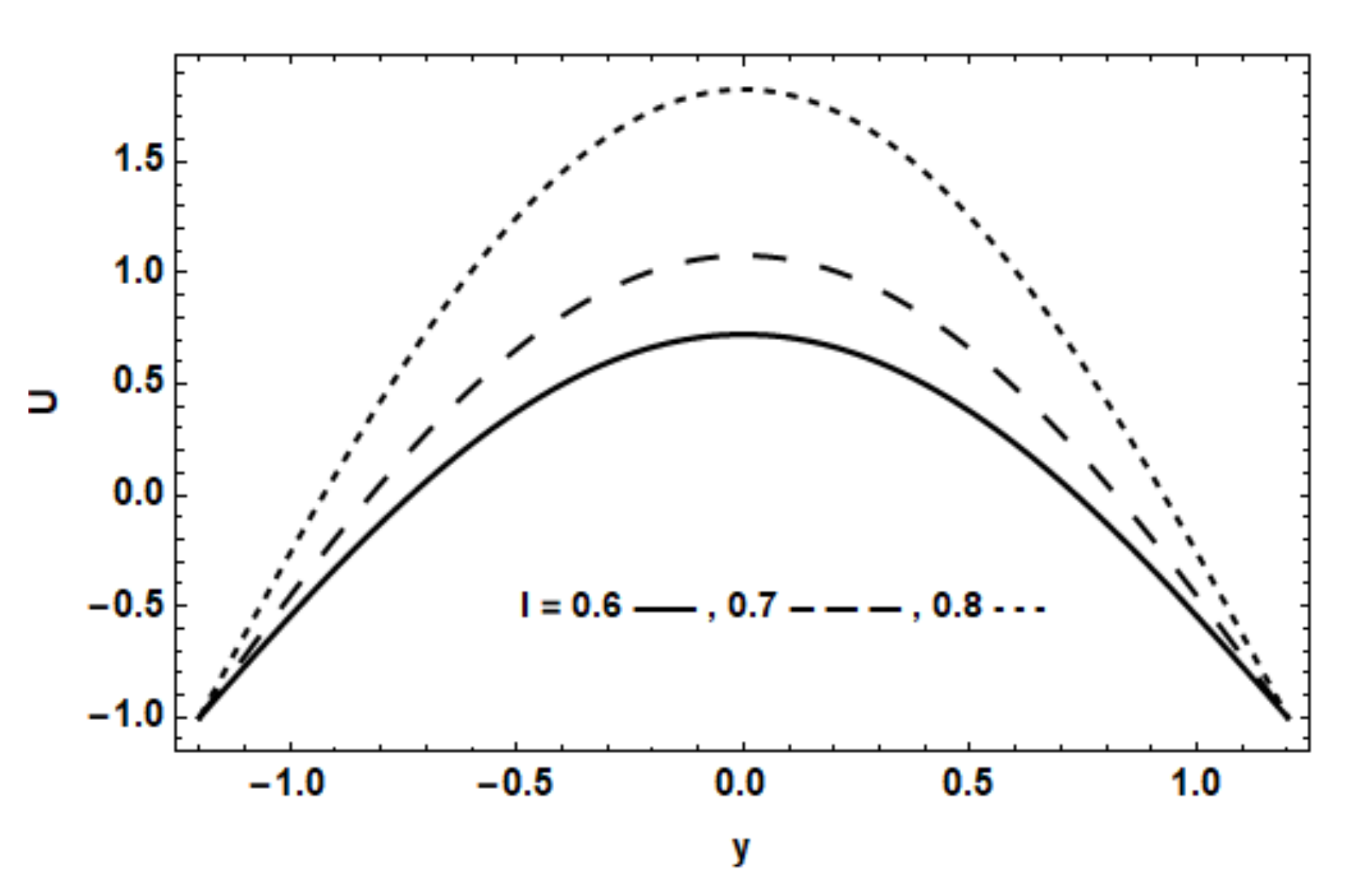
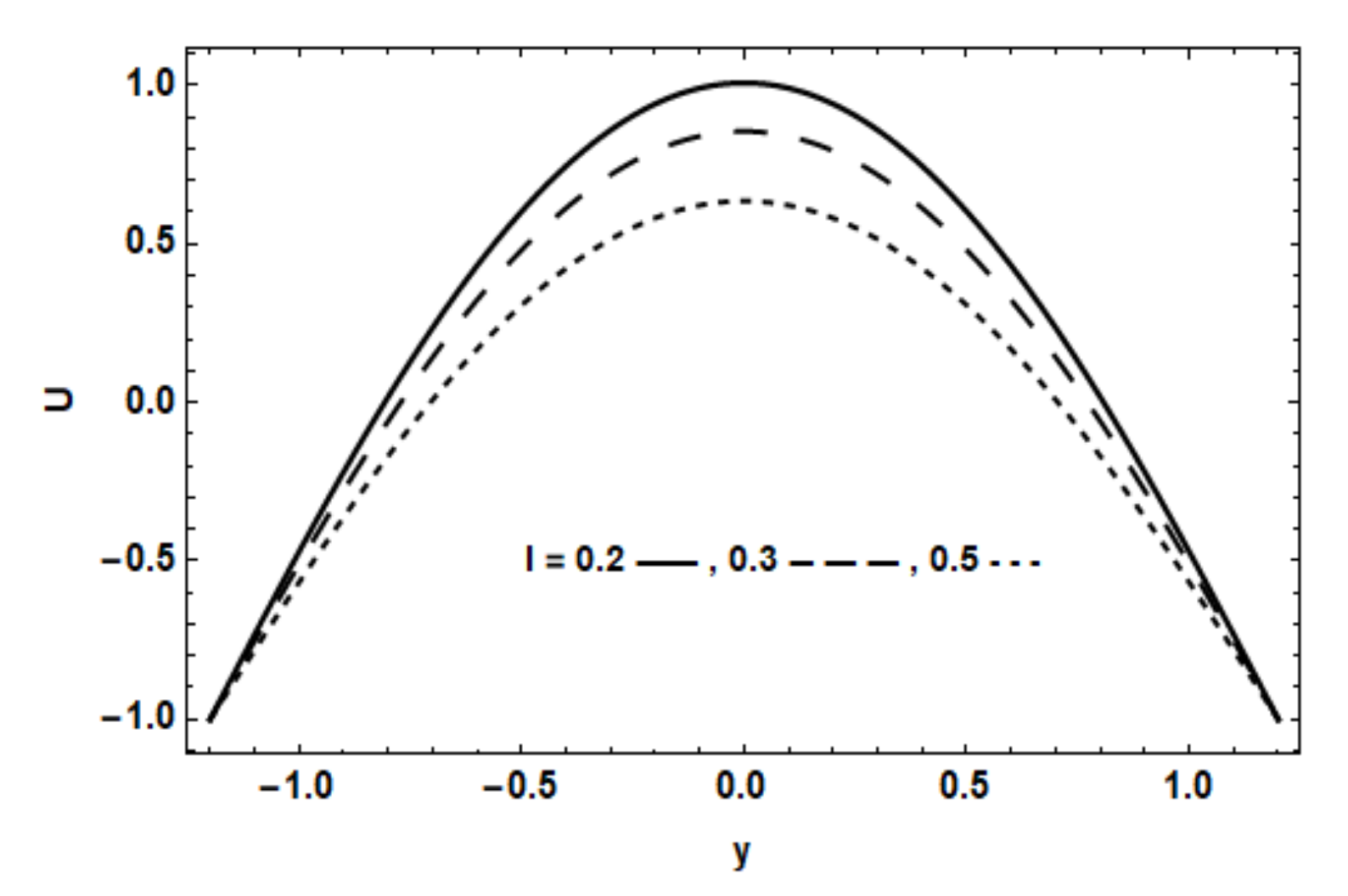
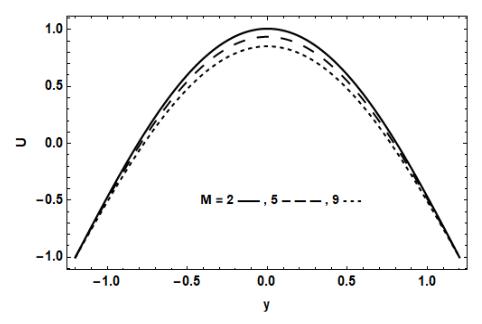
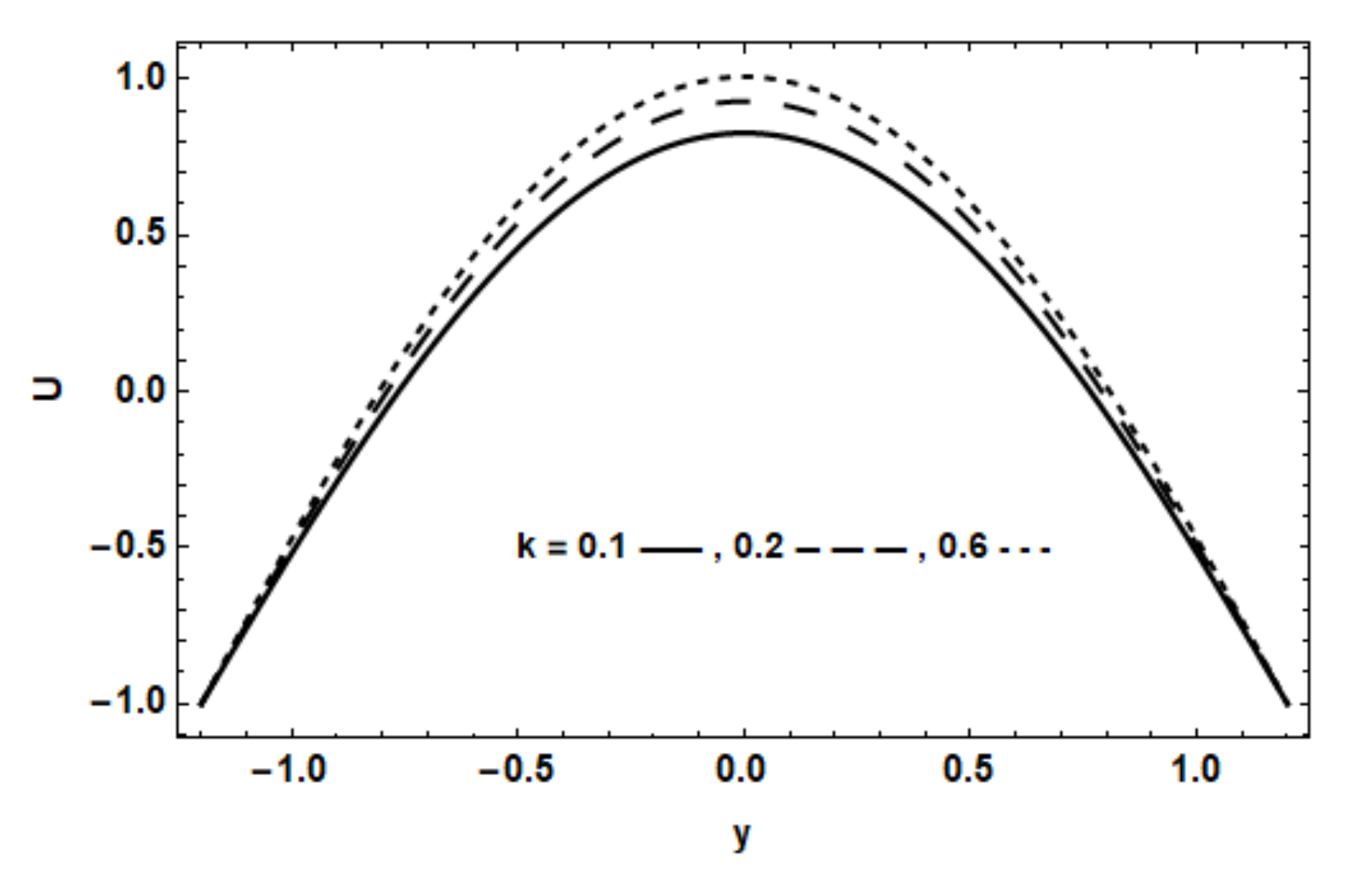
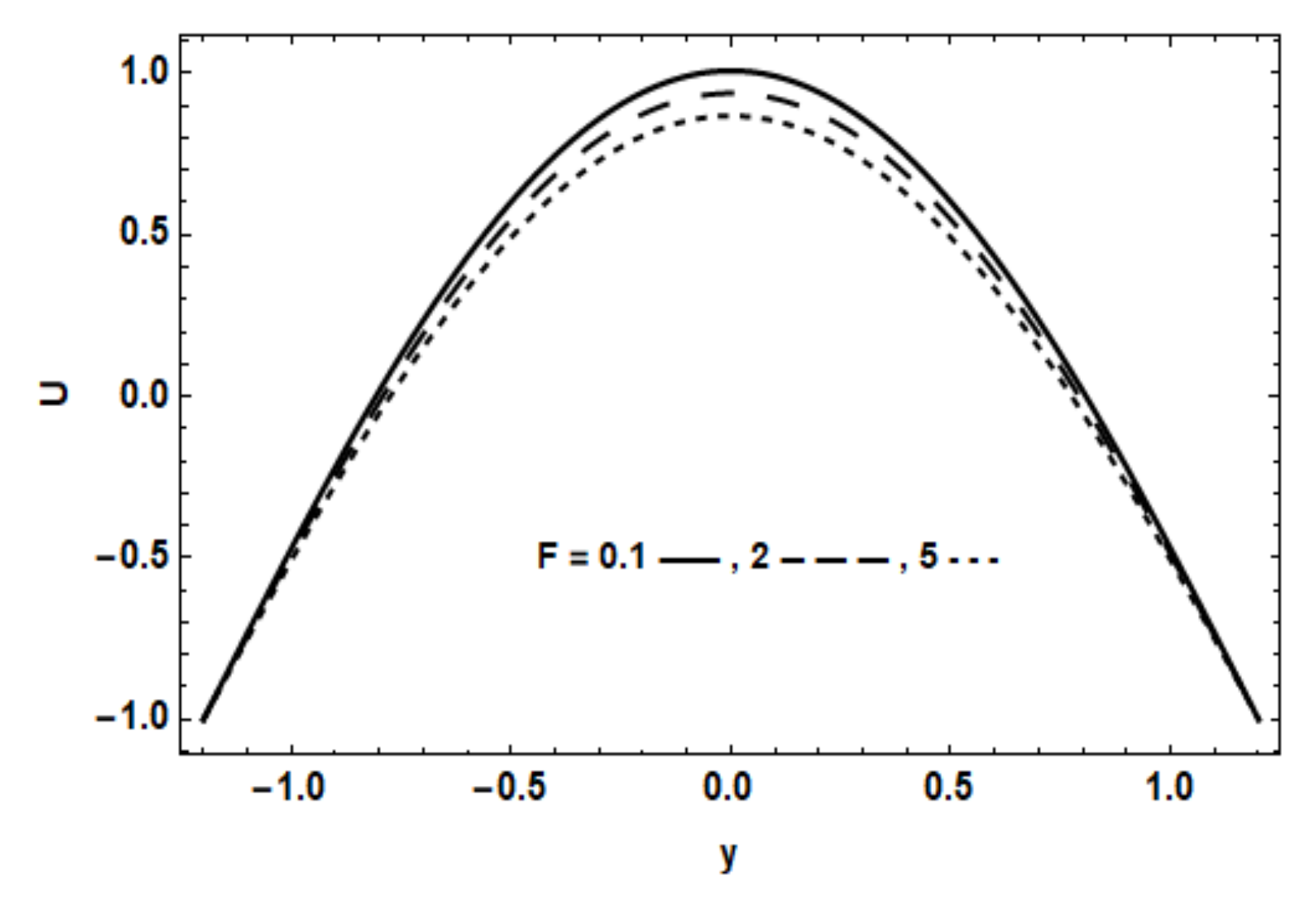
The Figure 2, Figure 3, Figure 4, Figure 5 and Figure 6 show the effects of physical parameters on the velocity distribution. It was found that the velocity decreases with increasing strength of the magnetic field, due to the increasing Lorentz force retarding the motion. The increase of the permeability parameter causes an increase in the velocity, because there are cavities between the fluid particles through porous medium which accelerate the motion. On the other hand, the velocity decreases by increasing the non-Darcy Forchheimer parameter. Additionally, it was found that the velocity decreases with increasing the values of the couple stress parameter up to l = 0.5, then the opposite occurs. There were some figures which showed that there were no effects of the Schmidt number, Brownian motion, thermophoresis, chemical reaction and Eckert number on the velocity, so these figures were excluded from the paper.
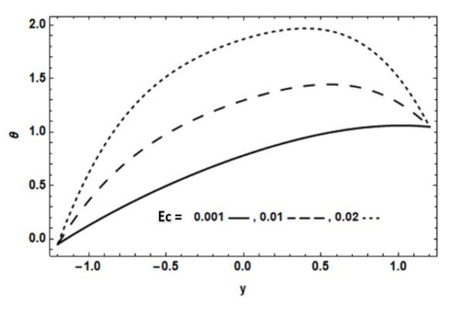
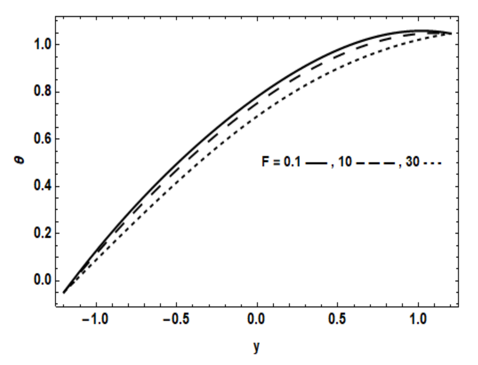
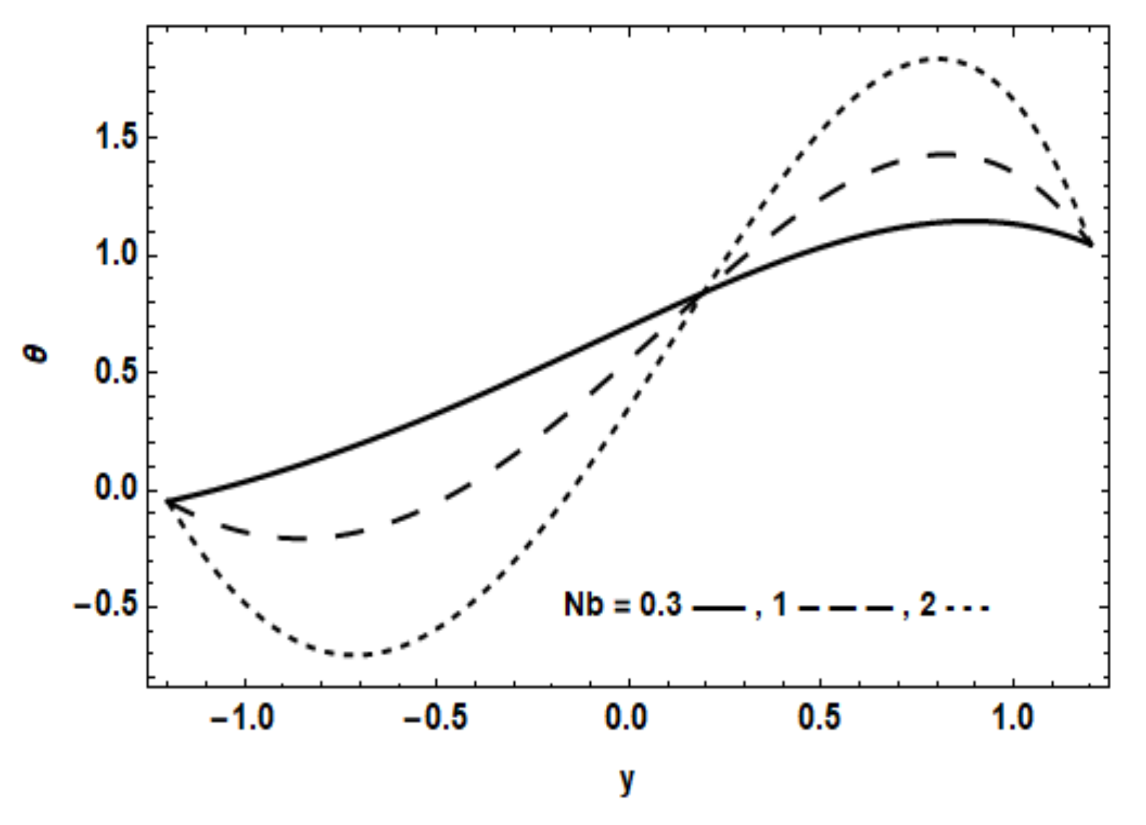
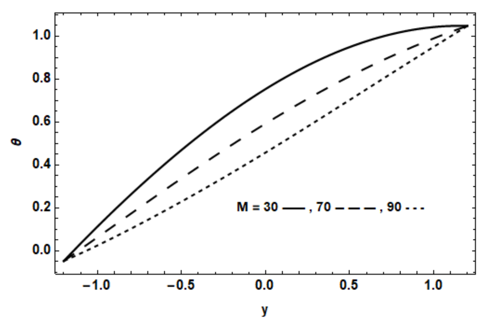
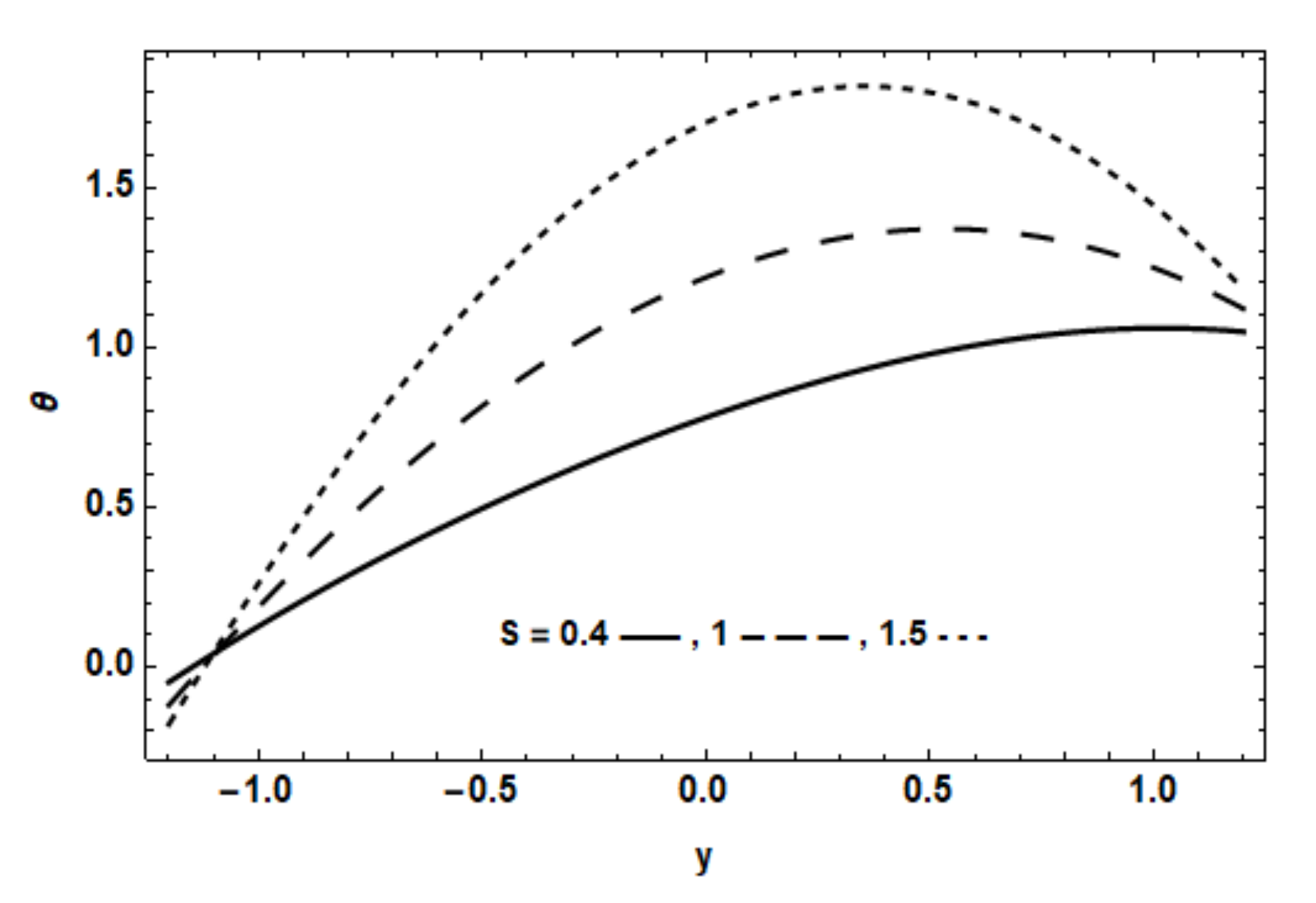
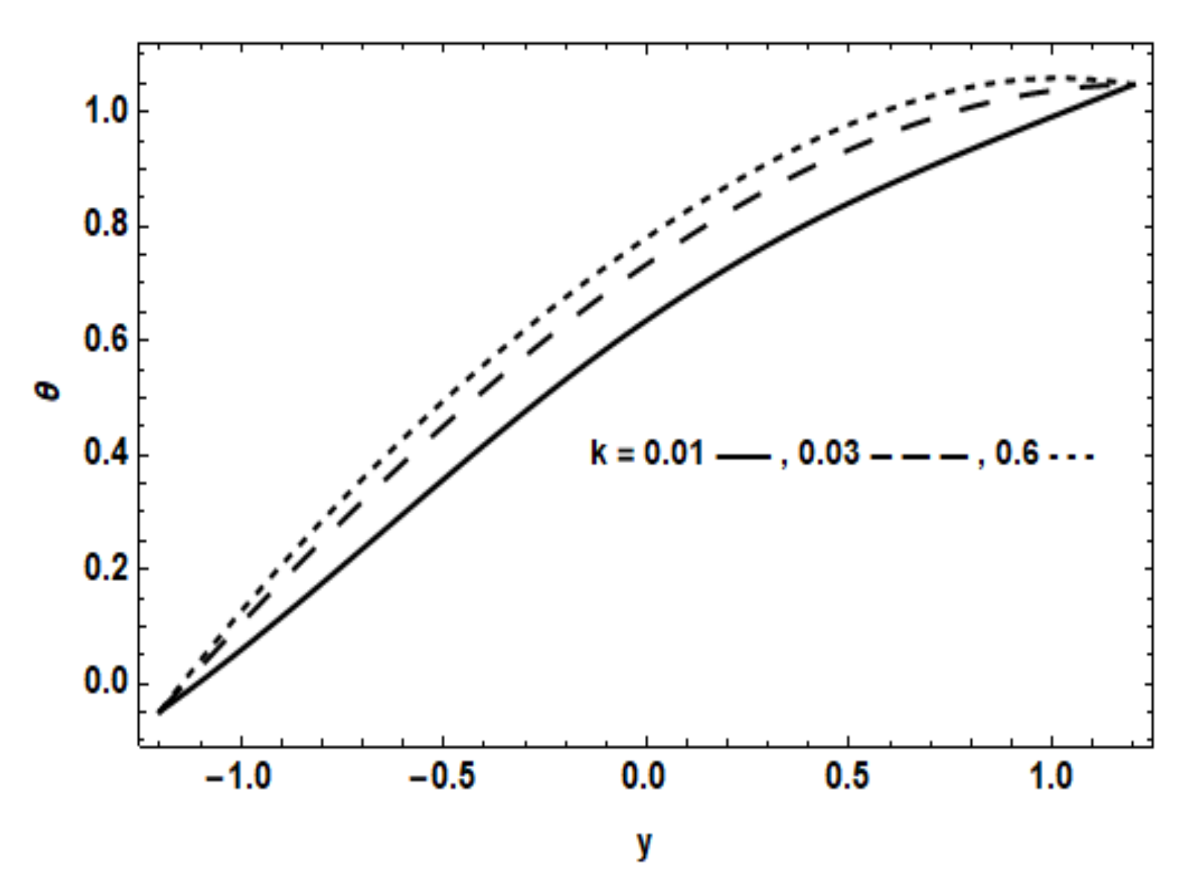
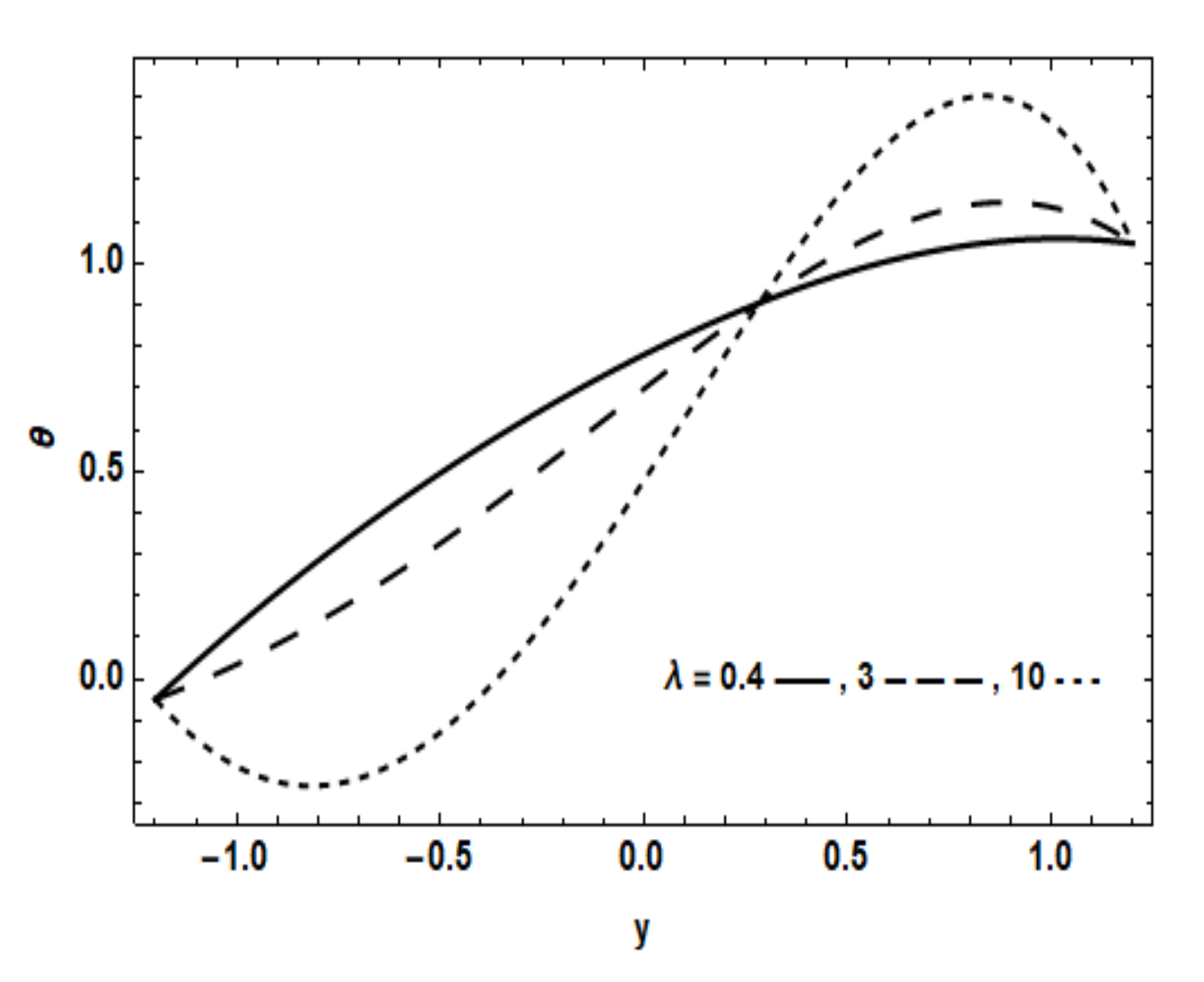
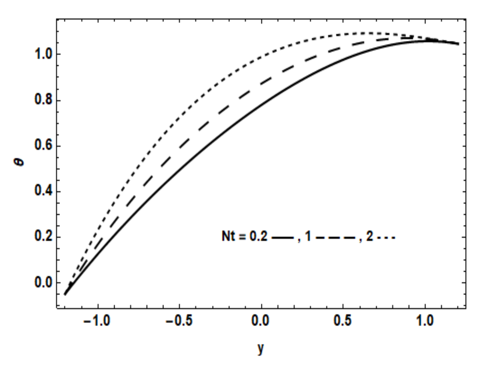
The effects of the physical parameters on the temperature distribution are illustrated in Figure 7, Figure 8, Figure 9, Figure 10, Figure 11, Figure 12, Figure 13, Figure 14 and Figure 15. It was found that the temperature decreases with increasing the values of the magnetic strength, and additionally, it decreases with increasing the non-Darcy parameter, while it increases with increasing the thermophoresis parameter, due to the nanoparticles increasing the thermal conductivity of the fluid. It was found from the figures that the temperature decreases with increasing the Brownian motion parameter up to y = 0.3, and for y > 0.3, the opposite occurs. Additionally, the temperature increases with increasing the Eckert number, heat generation and permeability parameter and decreases with the increase of the couple stress and Forchheimer parameter. Temperature decreases with increasing the chemical reaction parameter up to y = 0.3, and the opposite occurs for y > 0.3.
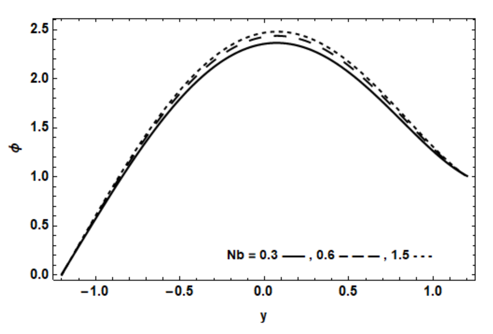
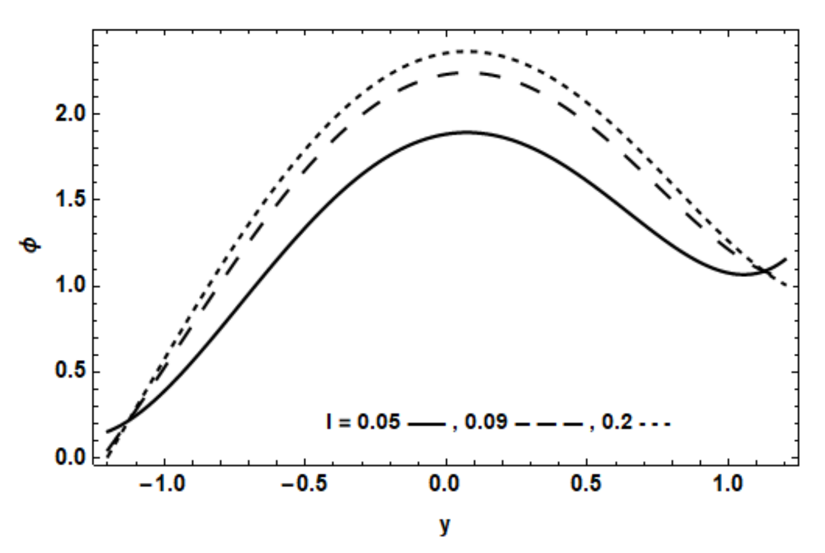
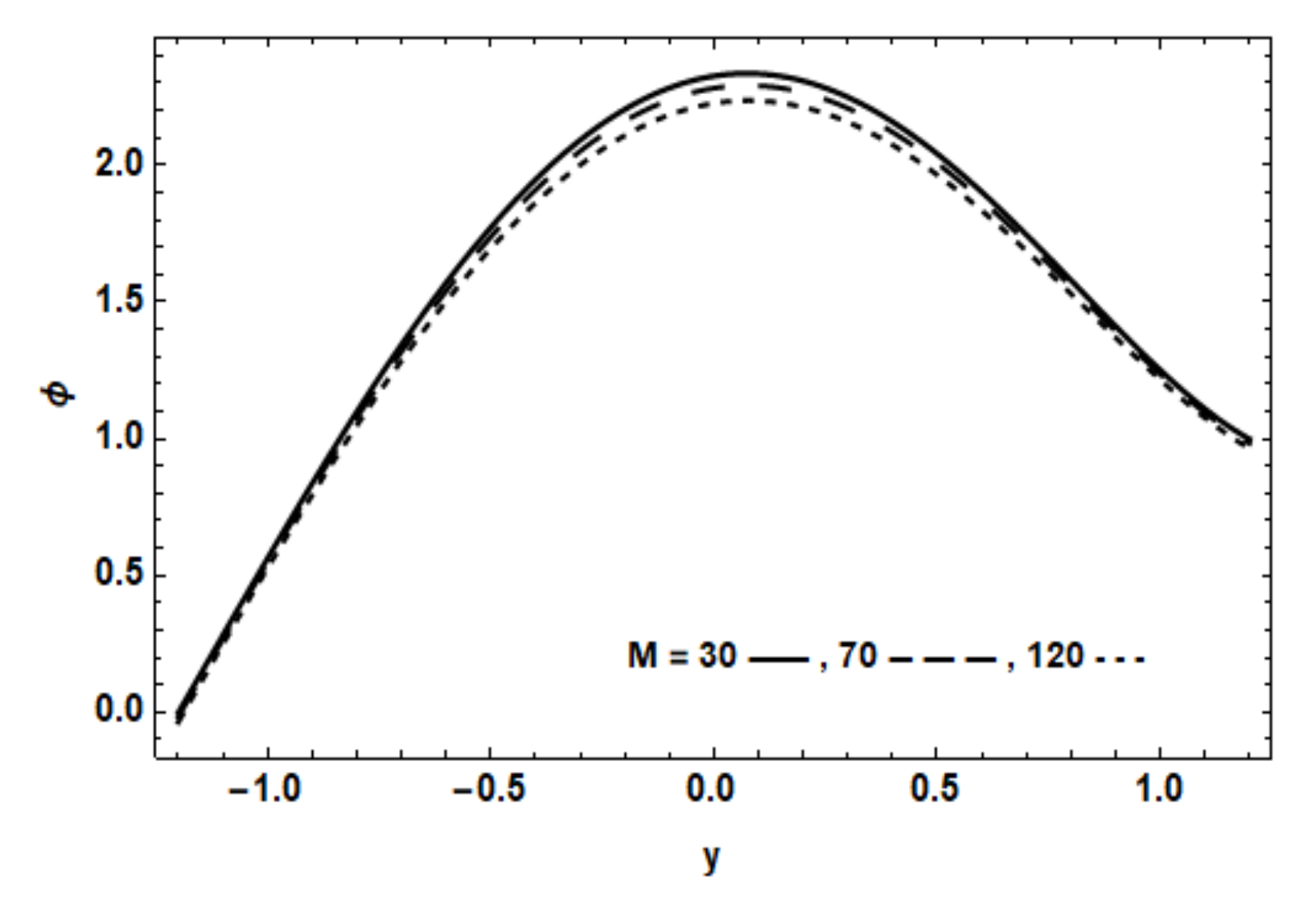
Furthermore, Figure 16, Figure 17, Figure 18, Figure 19, Figure 20 and Figure 21 illustrate the effects of the physical parameters of the problem on the nanoparticles’ concentration distributions. These figures show that concentration increases with increasing the chemical reaction, the couple stress and the Brownian motion parameter, while it decreases with increasing Schmidt number, thermophoresis and the magnetic field strength. There were no effects of the permeability parameter and non-Darcy parameter on the concentration.

5. Conclusions

This study dealt with the peristaltic motion of a nano-coupled stress fluid inside a horizontal channel of flexible walls. The heat transfer and the force of magnetic field were considered as well as the non-Darcy porous medium. Governing partial differential equations were simplified by using an approximations of long wavelength and low Reynolds number. The homotopy perturbation method was used to obtain the fluid velocity, temperature and nanoparticles’ concentration as functions of the problem physical parameters. The effects of these parameters were studied numerically and illustrated graphically. It was found that:
  • The fluid velocity decreased with the increasing of magnetic field and non-Darcy parameters.
  • The velocity, u, decreased with the increasing of the values of the couple stress parameter up to l = 0.5, then the opposite occurred.
  • The velocity, u, increased by increasing the permeability parameter k.
  • The temperature, θ , increased with increasing thermophoresis, the Eckert number, heat generation and the permeability parameters.
  • The temperature, θ , decreased with increasing the magnetic strength, couple stress and the non-Darcy parameters.
  • Temperature decreased with the increasing chemical reaction parameter for y > 0.3, and the opposite occurred up to y = 0.
  • The temperature decreased with increasing the Brownian motion parameter up to y = 0.3, and for y > 0.3, the opposite occurred (at λ = 0.4).
  • The concentration increased with increasing of the chemical reaction, couple stress and Brownian motion parameters.
  • The concentration decreased with increasing of the Schmidt number, thermophoresis and magnetic field strength parameters.

Author Contributions

Conceptualization, W.A.; Formal analysis, N.T.M.E. and R.A.A.; Method-ology, N.T.M.E.; Resources, R.A.A.; Writing – original draft, W.A.; Writing – review and editing, N.A.Z. and S.Y.M. All authors have read and agreed to the published version of the manuscript.

Funding

This research received no external funding.

Institutional Review Board Statement

Not applicable.

Informed Consent Statement

Not applicable.

Data Availability Statement

Data sharing not applicable.

Conflicts of Interest

The authors declare no conflict of interest.

Appendix A

n 0 = A 120 n 1 = A h 2 12 n 2 = 5 A h 4 24 1
n 3 = n 0 l 2 42 n 4 = n 1 l 2 20 n 5 = l 2 1 k + M
n 6 = n 3 n 5 72 l 2 n 7 = ( n 4 n 5 ) 42 l 2 n 8 = ( 5 n 4 n 5 h 2 ) 12 l 2
n 9 = F l 2 n 10 = 5 n 0 2 n 9 30 , 888 n 11 = n 1 2 n 9 1680
n 12 = 5 n 1 2 n 9 h 4 96 n 13 = n 1 2 n 9 18 , 480 h 2 n 14 = n 1 2 n 9 6048
n 15 = n 1 2 n 9 h 2 168 n 16 = 25 n 0 h 4 l 2 6 n 17 = 61 n 0 n 5 h 6 36
n 18 = 5563 n 9 n 1 2 h 6 15 , 120 n 19 = n 16 + n 17 + n 18 n 20 = 7 n 1 h 4 l 2 30
n 21 = 323 n 1 n 5 h 6 3360 n 22 = 74 , 851 n 9 n 1 2 h 8 332 , 640 n 23 = 25 n 0 h 6 l 2 2
n 24 = 61 n 0 n 5 h 8 12 n 25 = 5563 n 9 n 1 2 h 8 5040 n 26 = n 20 + n 21 + n 22
n 27 = n 23 + n 24 + n 25 n 28 = n 26 n 27 n 29 = n 6 + n 11 + n 14
n 30 = n 3 + n 7 + n 15 n 31 = n 4 + n 8 + n 12 n 32 = 130 n 0 n 9 n 10
n 33 = 78 n 1 n 9 n 10 + 110 n 0 n 9 n 13 n 34 = 13 n 5 n 10 + 90 n 0 n 9 n 29 n 35 = 66 n 1 n 9 n 13 + 26 1 + n 2 n 9 n 10
n 36 = n 34 + n 35 n 37 = 1716 n 10 l 2 + 11 n 5 n 13 + 70 n 0 n 9 n 30 n 38 = 54 n 1 n 9 n 29 + 22 1 + n 2 n 9 n 13
n 39 = n 37 + n 38 n 40 = 990 n 13 l 2 + 9 n 5 n 29 + 50 n 0 n 9 n 31 n 41 = 42 n 1 n 9 n 30 + 18 1 + n 2 n 9 n 29
n 42 = n 40 + n 41 n 43 = 504 n 29 l 2 + 7 n 5 n 30 + 30 n 0 n 9 n 19 n 44 = 30 n 1 n 9 n 31 + 14 1 + n 2 n 9 n 30
n 45 = n 43 + n 44 n 46 = 210 n 30 l 2 + 5 n 5 n 31 10 n 0 n 9 n 28 n 47 = 18 n 1 n 9 n 19 + 10 1 + n 2 n 9 n 31
n 48 = n 46 + n 47 n 49 = 60 n 31 l 2 + 3 n 5 n 19 n 50 = 6 n 1 n 9 n 28 + 6 1 + n 2 n 9 n 19
n 51 = n 49 + n 50 n 52 = n 5 n 28 + 2 1 + n 2 n 9 n 28 6 n 19 l 2
n 53 = h 14 n 32 h 4 306 + n 33 h 2 240 n 36 182 n 54 = h 8 n 39 h 4 132 n 42 h 2 90 + n 45 56
n 55 = h 2 n 48 h 4 30 + n 51 h 2 12 + n 52 2 n 56 = n 53 + n 54 + n 55
n 57 = h 16 n 32 h 4 116 , 280 n 33 h 2 73 , 440 + n 36 43 , 680 n 58 = h 10 n 39 h 4 24 , 024 n 42 h 2 11 , 880 + n 45 5040
n 59 = h 4 n 48 h 4 1680 n 51 h 2 360 n 52 24 n 60 = n 57 + n 58 n 59 n 56 2 h 2
n 61 = n 32 2 , 441 , 880 n 62 = n 33 1 , 395 , 360 n 63 = n 36 742 , 560
n 64 = n 39 360 , 360 n 65 = n 42 154 , 440 n 66 = n 45 55 , 440
n 67 = n 48 15 , 120 n 68 = n 51 2520 n 69 = n 52 120
n 70 = n 56 6 n 71 = n 65 n 10 n 72 = n 13 n 66
n 73 = n 67 n 29 n 74 = n 30 n 68 n 75 = n 0 n 31 n 69
n 76 = n 19 + n 70 n 1 n 77 = n 2 + n 28 + n 60 n 78 = M P r E A 2
n 79 = n 78 51 , 840 n 80 = n 78 h 2 2688 n 78 2016 M
n 81 = n 78 180 M l 2 + n 78 h 2 180 M n 78 h 4 480 n 78 h 4 1728
n 82 = n 78 h 2 24 M l 2 n 78 h 4 48 M + 10 n 78 h 6 1152
n 84 = 25 n 78 h 8 1152 + N b P r 8 h 2 + N t P r 8 h 2 + S 4
n 83 = S 12 h
n 85 = h S 12
n 86 = n 79 h 10 n 80 h 8 n 81 h 6 n 82 h 4 + n 84 h 2 n 87 = λ 12 h S c
n 88 = 3 h n 87 n 89 = h 2 n 87 n 90 = h 2 n 88
n 91 = 130 n 0 n 10 n 78 A 2 n 92 = 6240 n 0 n 10 n 78 M A 2 n 93 = 110 n 0 n 13 n 78 A 2
n 94 = 78 n 1 n 10 n 78 A 2 n 95 = n 92 n 93 n 94 n 96 = 343 , 200 n 0 n 10 n 78 M A 2 l 2
n 97 = 18 , 720 n 0 n 10 n 78 M A 2 l 2 n 98 = 4400 n 0 n 13 n 78 M A 2 n 99 = 1872 n 1 n 10 n 78 M A 2
n 100 = 90 n 0 n 29 n 78 A 2 n 101 = 66 n 1 n 13 n 78 A 2 n 102 = 26 ( 1 + n 2 )   n 10 n 78 A 2
n 103 = n 96 + n 97 + n 98 + n 99 n 100 n 101 n 102 n 104 = 158 , 400 n 0 n 13 n 78 M A 2 l 2
n 105 = 102 , 960 n 1 n 10 n 78 M A 2 l 2 n 106 = 13 , 200 n 0 n 13 n 78 M A 2 l 2 n 107 = 2880 n 0 n 29 n 78 M A 2
n 108 = 1320 n 1 n 13 n 78 M A 2 n 109 = 70 n 0 n 30 n 78 A 2 n 110 = 54 n 1 n 29 n 78 A 2
n 111 = 22 1 + n 2 n 13 n 78 A 2 n 112 = S n 79 n 113 = n 104 + n 105 + n 106
n 114 = n 107 + n 108 n 109 n 115 = n 110 + n 111 n 112 n 116 = n 113 + n 114 n 115
n 117 = 5 N b P r n 79 h + 10 N t P r n 79 h n 118 = 60 , 480 n 0 n 29 n 78 M A 2 l 2
n 119 = 47 , 520 n 1 n 13 n 78 M A 2 l 2 n 120 = 8640 n 0 n 29 n 78 M A 2 l 2 n 121 = 1680 n 0 n 30 n 78 M A 2
n 122 = 864 n 1 n 29 n 78 M A 2 n 123 = 50 n 0 n 31 n 78 A 2

References

  1. Latham, T.W. Fluid Motion in Peristaltic Pumps. Master’s Thesis, MIT, Cambridge, MA, USA.
  2. Shapiro, A.H.; Jaffrin, M.T.; Weiberg, S.L. Peristaltic pumping with long wavelength at low Reynolds number. J. Fluid Mech. 1969, 37, 799–825. [Google Scholar] [CrossRef]
  3. Eldabe, N.T.M.; Abou Zeid, M.Y.; Mohamed, M.A.A.; Abd-Elmoneim, M.M. MHD peristaltic flow of non-Newtonian power—Law nano fluid through a non-darcy porous medium inside a non-uniform inclined channel. Arch. Appl. Mech. 2021, 91, 1067–1077. [Google Scholar] [CrossRef]
  4. Eldabe, N.T.; Zaghrout, A.A.; Ramaden, S.F.; Azzam, H.A. Simultaneous effects of radiation, magnetic field on peristaltic flow of Carreau nano fluid submerged in gyrotactivc microorganism with heat and mass transfer. Heat Transf. 2021, 50, 1198–1216. [Google Scholar] [CrossRef]
  5. Eldabe, N.T.; Moatimed, G.M.; Sayed, A. Effect of the magnetic induction on the peristaltic Eyring—Prandtl nanofluid through porous medium. Int. J. Appl. Electromagn. Mech. 2020, 63, 279–298. [Google Scholar] [CrossRef]
  6. Eldabe, N.T.; Ramadan, S.F.; Awad, A.S. Analytical and Numerical treatment to study the effects of Hall currents with viscous dissipation, heat absorption and chemical reaction on peristaltic flow of Carreau nanofluid. Therm. Sci. 2021, 25, 181–196. [Google Scholar] [CrossRef]
  7. Hayat, T.; Abbasi, F.M.; Al-Yami, M.; Monaqual, S. Slip and Joule heating effects in mixed convection peristaltic transport of nanofluid with Soret and Duffour effects. J. Mol. Liq. 2014, 194, 93–99. [Google Scholar] [CrossRef]
  8. Akram, S.; Nadeen, S. Consequence of nanofluid on peristaltic transport of hyperbolic tangent fluid model in the occurrence of apt (tending) magnetic field. J. Magn. Magn. Mater. 2014, 358–359, 183–191. [Google Scholar] [CrossRef]
  9. Akbar, N.S.; Nadeem, S.; Hayat, T.; Hendi, A.A. Peristaltic flow of a nanofluid in a non-uniform tube. Heat Mass Transf. 2012, 48, 451–459. [Google Scholar] [CrossRef]
  10. Akbar, N.S.; Nadeem, S.; Hayat, T.; Hendi, A. Peristaltic flow of a nanofluid with slip effects. Meccanica 2012, 47, 1283–1294. [Google Scholar] [CrossRef]
  11. Abbas, W.; Magdy, M.M. Heat and Mass Transfer Analysis of Nanofluid Flow Based on, and over a Moving Rotating Plate and Impact of Various Nanoparticle Shapes. Math. Probl. Eng. 2020, 2020. [Google Scholar] [CrossRef]
  12. Eldabe, N.T.; Attia, H.A.; Essawy, M.A.I.; Ramadan, A.A.; Abdel-Hamid, A.H. Non linear heat and mass transfer in MHD Homann nanofluid flow through a porous medium with chemical reaction, heat generation and uniform inflow. Eur. Phys. J. Plus 2016, 131, 305. [Google Scholar] [CrossRef]
  13. Hayat, T.S.; hafique, M.; Tanveer, A.; Alsaedi, A. Hall and ion slip effects on peristaltic flow of Jeffrey nanopfluid with Joule heating. J. Magn. Magn. Mater. 2016, 407, 51–59. [Google Scholar] [CrossRef]
  14. Hasona, W.M.; El-Shekhipy, A.A.; Ibrahim, M.G. Combined effects of magnetohydrodynamic and temperature dependent viscosity on peristaltic flow of Jeffrey nanofluid through a porous medium: Applications to oil refinement. Int. J. Heat Mass Transf. 2018, 126, 700–714. [Google Scholar] [CrossRef]
  15. Riaz, A.; Khan, S.U.D.; Zeeshan, A.; Khan, S.U.; Hassan, M.; Muhammad, T. Thermal analysis of peristaltic flow of nanosized particles within a curved channel with second-order partial slip and porous medium. J. Therm. Anal. Calorim. 2021, 143, 1997–2009. [Google Scholar] [CrossRef]
  16. Moghadasi, R.; Rostami, A.; Hemmati-Sarapardeh, A. Application of nanofluids for treating fines migration during hydraulic fracturing: Experimental study and mechanistic understanding. Adv. Geo-Energy Res. 2019, 3, 198–206. [Google Scholar] [CrossRef]
  17. Shivappa Kotnurkar, A.; Giddaiah, S. Double diffusion on peristaltic flow of nanofluid under the influences of magnetic field, porous medium, and thermal radiation. Eng. Rep. 2021, 2, e12111. [Google Scholar] [CrossRef]
  18. Abbasi, A.; Mabood, F.; Farooq, W.; Khan, S.U. Radiation and joule heating effects on electroosmosis-modulated peristaltic flow of Prandtl nanofluid via tapered channel. Int. Commun. Heat Mass Transf. 2012, 123, 105183. [Google Scholar]
  19. Ahmed, B.; Hayat, T.; Abbasi, F.M.; Alsaedi, A. Mixed convection and thermal radiation effect on MHD peristaltic motion of Powell-Eyring nanofluid. Int. Commun. Heat Mass Transf. 2021, 126, 105320. [Google Scholar] [CrossRef]
  20. Eldabe, N.T.M.; El-Mohandis, S.M.G. Effect of couple stresses on pulsatile hydromagnetic Poiseuille flow. Fluid Dyn. Res. 1995, 15, 313–324. [Google Scholar] [CrossRef]
  21. Devakar, M.; Iyengar, T.K.V. Stokes problems for an incompressible couple stress fluid. Nonlinear Anal. Modeling Control 2008, 1, 181–190. [Google Scholar] [CrossRef]
  22. Srinivasacharya, D.; srinivasacharyulu, N.; Odelu, O. Flow and heat transfer of couple stress fluid in a porous channel with expanding and contracting walls. Int. Commun. Heat Mass Transf. 2009, 36, 180–185. [Google Scholar] [CrossRef]
  23. Eldabe, N.T.M.; Hassan, A.A.; Mohamed, M.A.A. Effect of couple stresses on the HHD of a non-Newtonian unsteady flow between two parallel porous plates. Z. Naturforsch. 2003, 58a, 204–210. [Google Scholar] [CrossRef] [Green Version]
  24. Eldabe, N.T.M.; Hassan, A.A.; Mohamed, M.A.A. Effect of couple stresses on a pulsatile magnetohydrodynamic viscoelastic flow through a channel bounded by two permeable parallel plates. Mech. Mech. Eng. 2004, 7, 5–14. [Google Scholar]
  25. Devakar, M.; tyengar, T.K.V. Run up flow of a couple stress fluid. Nonlinear Analysis. Modeling Control 2010, 15, 29–37. [Google Scholar]
  26. Eldabe, N.T.M.; Hassan, M.A.; Abou-Zaid, M.Y. Wall properities effect on peristaltic motion of a coupled stress fluid with heat and mass transfer through a porous medium. J. Eng. Mech. 2016, 142, 04015102. [Google Scholar] [CrossRef]
  27. Srinivasacharya, D.; Kaladhar, K. Mixed convection in a coupled stress fluid with Soret and Dufour effects. Int. J. Appl. Math. Mech. 2011, 7, 59–71. [Google Scholar]
  28. Eldabe, N.T.; Kamel, K.A.; Ramadan, S.F.; Saad, R.A. Peristaltic motion of Eyring—Powell nanofluid with couple stresses and heat and mass transfer through a porous media under the effect of magnetic field inside asymmetric vertical channel. J. Adv. Res. Fluid Mech. Therm. Sci. 2020, 68, 58–71. [Google Scholar] [CrossRef]
  29. Govindarajan, A.; Siva, E.P.; Vidhya, M. Combined effect of heat and mass transfer on MHD peristaltic transport of couple stress fluid in a inclined asymmetric channel through a porous medium. Int. J. Pure Appl. Math. 2015, 105, 685–707. [Google Scholar] [CrossRef] [Green Version]
  30. Eldabe, N.T.; Kamel, K.A.; Ramadan, S.F.; Saad, R.A. Impacts of couple stress with magnetic field and heat absorption on peristaltic flow of a Power—Law fluid containing nanoparticles. Heat Transf. 2020. [Google Scholar] [CrossRef]
  31. Ramesh, K. Influence of heat and mass transfer on peristaltic flow of a couple stress fluid through porous medium in the presence of inclined magnetic field in an inclined asymmetric channel. J. Mol. Liq. 2016, 219, 256–271. [Google Scholar] [CrossRef]
  32. Attia, H.A.; Abbas, W.; Abdeen, M.A.M.; Said, A.A.M. Heat transfer between two parallel porous plates for Couette flow under pressure gradient and Hall current. Sadhana 2015, 40, 183–197. [Google Scholar] [CrossRef]
  33. Bég, O.A.; Zueco, J.; Takhar, H.S. Unsteady magnetohydrodynamic Hartmann-Couette flow and heat transfer in a Darcian channel with Hall current, ionslip, viscous and Joule heating effects: Network numerical solutions. Commun. Nonlinear Sci. Numer. Simul. 2009, 14, 1082–1097. [Google Scholar] [CrossRef]
  34. Forchheimer, P. Wasserbewegung durch boden. Z. Ver. Dtsch. Ing. 1901, 45, 1782–1788. [Google Scholar]
  35. Girault, V.; Wheeler, M.F. Numerical discretization of a Darcy-Forchheimer model. Numer. Math. 2008, 110, 161–198. [Google Scholar] [CrossRef]
  36. Ambreen, T.; Saleem, A.; Park, C.W. Analysis of hydro-thermal and entropy generation characteristics of nanofluid in an aluminium foam heat sink by employing Darcy-Forchheimer-Brinkman model coupled with multiphase Eulerian model. Appl. Therm. Eng. 2020, 173, 115231. [Google Scholar] [CrossRef]
  37. Khan, M.I.; Alzahrani, F.; Hobiny, A. Simulation and modeling of second order velocity slip flow of micropolar ferrofluid with Darcy-Forchheimer porous medium. J. Mater. Res. Technol. 2020, 9, 7335–7340. [Google Scholar] [CrossRef]
  38. Farooq, U.; Hussain, M.; Ijaz, M.A.; Khan, W.A.; Farooq, F.B. Impact of non-similar modeling on Darcy-Forchheimer-Brinkman model for forced convection of Casson nano-fluid in non-Darcy porous media. Int. Commun. Heat Mass Transf. 2021, 125, 105312. [Google Scholar] [CrossRef]
  39. Haider, F.; Hayat, T.; Alsaedi, A. Flow of hybrid nanofluid through Darcy-Forchheimer porous space with variable characteristics. Alex. Eng. J. 2021, 60, 3047–3056. [Google Scholar] [CrossRef]
  40. Abbas, W.; Magdy, M.M.; Abdelgaber, K.M.; Abdeen, M.A.M. Unsteady magnetohydrodynamic flow with heat and mass transfer between two parallel walls under variable magnetic field. High Temp. 2020, 58, 284–291. [Google Scholar] [CrossRef]
Figure 1. Sketch of the problem.
Coatings 11 00910 g001
Figure 2. Fluid velocity, u, is drawn against y for values of l = 0.6, 0.7, 0.8, where A = 5, k = 0.6, F = 0.1, P r = 0.7, S c = 0.1, M = 2, h = 1.2, S = 0.4, N b = 0.3, N t = 0.2, Ec = 0.001, λ = 0.4.
Coatings 11 00910 g002
Figure 3. Fluid velocity, u, is drawn against y for values of l = 0.2, 0.3, 0.5, where A = 5, k = 0.6, F = 0.1, P r = 0.7, S c = 0.1, M = 2, h = 1.2, S = 0.4, N b = 0.3, N t = 0.2, Ec = 0.001, λ = 0.4.
Coatings 11 00910 g003
Figure 4. Effect of M on velocity, u, where, A = 5, l = 0.2, F = 0.1, P r = 0.7, S c = 0.1, k = 0.6, h = 1.2, S = 0.4, N b = 0.3, N t = 0.2, Ec = 0.001, λ = 0.4.
Coatings 11 00910 g004
Figure 5. Effect of k on velocity, u, where, A = 5, l = 0.2, F = 0.1, P r = 0.7, S c = 0.1, M = 2, h = 1.2, S = 0.4, N b = 0.3,   N t = 0.2, Ec = 0.001, λ = 0.4.
Coatings 11 00910 g005
Figure 6. Effect of F on velocity, u, where, A = 5, l = 0.2, k = 0.6, P r = 0.7, S c = 0.1, M = 2, h = 1.2, S = 0.4, N b = 0.3, N t = 0.2, Ec = 0.001, λ = 0.4.
Coatings 11 00910 g006
Figure 7. Effect of Ec on temperature, θ , where, A = 5, l = 0.2, F = 0.1, P r = 0.7, S c = 0.1, M = 2, h = 1.2, S = 0.4, λ = 0.4, N t = 0.2, N b = 0.3, k = 0.6.
Coatings 11 00910 g007
Figure 8. Effect of F on temperature, θ , where, A = 5, l = 0.2, Ec = 0.001, P r = 0.7, S c = 0.1, M = 2, h = 1.2, S = 0.4, λ = 0.4, N t =0.2, N b = 0.3, k = 0.6.
Coatings 11 00910 g008
Figure 9. Effect of N b on temperature, θ , where, A = 5, l = 0.2, F = 0.1, P r = 0.7, S c = 0.1, M = 2, h = 1.2, S = 0.4, λ = 0.4, N t = 0.2, Ec = 0.001, k = 0.6.
Coatings 11 00910 g009
Figure 10. Effect of M on temperature, θ , where, A = 5, l = 0.2, F = 0.1, P r = 0.7 Ec = 0.001, N b = 0.3, h = 1.2, S = 0.4, λ = 0.4, N t = 0.2, S c = 0.1, k = 0.6.
Coatings 11 00910 g010
Figure 11. Effect of S on temperature, θ , where, A = 5, l = 0.2, F = 0.1, P r = 0.7, S c = 0.1, N b = 0.3, h = 1.2, M = 2, λ = 0.4, N t = 0.2, Ec = 0.001, k = 0.6.
Coatings 11 00910 g011
Figure 12. Effect of k on temperature, θ , where, A = 5, l = 0.2, F = 0.1, P r = 0.7, S c = 0.1, M = 2, h = 1.2, S = 0.4,   N b = 0.3, N t = 0.2, Ec = 0.001, λ = 0.4.
Coatings 11 00910 g012
Figure 13. Effect of λ on temperature, θ , where, A = 5, l = 0.2, F = 0.1, P r = 0.7, S c = 0.1, M = 2, h = 1.2, S = 0.4, N b = 0.3,   N t = 0.2, Ec = 0.001, k = 0.6.
Coatings 11 00910 g013
Figure 14. Effect of N t on temperature, θ , where, A = 5, l = 0.2, F = 0.1, P r = 0.7, N b = 0.3, M = 2, h = 1.2, S = 0.4, λ = 0.4, S c = 0.1, Ec = 0.001, k = 0.6.
Coatings 11 00910 g014
Figure 15. Effect of l on temperature, θ , where, A = 5, F = 0.1, P r = 0.7, N b = 0.3, M = 2, h = 1.2, S = 0.4, λ = 0.4, S c = 0.1, Ec = 0.001, k = 0.6   N t = 0.2.
Coatings 11 00910 g015
Figure 16. Effect of N b on concentration, φ , where, A = 5, l = 0.2, F = 0.1, P r = 0.7, S c = 0.1, M = 2, h = 1.2, S = 0.4, Ec = 0.001,   N t = 0.2, k = 0.6, λ = 0.4.
Coatings 11 00910 g016
Figure 17. Effect of N t on concentration, φ , where, A = 5, l = 0.2, F = 0.1, P r = 0.7, S c = 0.1, M = 2, h = 1.2, S = 0.4, Ec = 0.001, N b = 0.3, k = 0.6, λ = 0.4.
Coatings 11 00910 g017
Figure 18. Effect of S c on concentration, φ , where, A = 5, l = 0.2, F = 0.1, P r = 0.7, N t = 0.2, M = 2, h = 1.2, S = 0.4, Ec = 0.001, N b = 0.3, k = 0.6, λ = 0.4.
Coatings 11 00910 g018
Figure 19. Effect of l on concentration, φ , where, A = 5, λ = 0.4, F = 0.1, P r = 0.7, N t = 0.2, M = 2, h = 1.2, S = 0.4, Ec = 0.001, N b = 0.3, k = 0.6, S c = 0.1.
Coatings 11 00910 g019
Figure 20. Effect of λ on concentration, φ , where, A = 5, l = 0.2, F = 0.1, P r = 0.7, S c = 0.1, M = 2, h = 1.2, S = 0.4, N b = 0.3, N t = 0.2, k = 0.6 Ec = 0.001.
Coatings 11 00910 g020
Figure 21. Effect of M on concentration, φ , where, A = 5, l = 0.2, F = 0.1, P r = 0.7, S c = 0.1, Ec = 0.001, h = 1.2, S = 0.4, N b = 0.3, N t = 0.2, k = 0.6, λ = 0.
Coatings 11 00910 g021
Publisher’s Note: MDPI stays neutral with regard to jurisdictional claims in published maps and institutional affiliations.