Article

Corrosion Protection of Injection Molded Porous 440C Stainless Steel by Electroplated Zinc Coating

1
Department of Chemistry, University of Eastern Finland, P.O. Box 111, FI-80101 Joensuu, Finland
2
Karelia University of Applied Sciences, FI-80200 Joensuu, Finland
*
Authors to whom correspondence should be addressed.
Coatings 2021, 11(8), 949; https://doi.org/10.3390/coatings11080949
Submission received: 20 May 2021 / Revised: 4 August 2021 / Accepted: 5 August 2021 / Published: 9 August 2021
(This article belongs to the Section Corrosion, Wear and Erosion)

Abstract

:
Zinc electroplating was used to enhance corrosion resistance of porous metal injection molded 440C stainless steel. Controlled porosity was achieved by the powder space holder technique and by using sodium chloride as a space holder material. The internal pore structure of porous 440C was deposited by zinc using electroplating with three different electrolytes of zinc acetate, zinc sulfate, and zinc chloride. Our results show that all zinc depositions on porous 440C samples significantly improved corrosion resistance. The lowest corrosion was observed with zinc acetate at 30 wt.% porosity. The developed zinc coated porous 440C samples have potential in applications in corrosive environments.

Graphical Abstract

1. Introduction

Stainless steels are widely used in various applications, ranging from simple everyday items such as cutlery and kitchen equipment to highly complicated products in automotive and medical industries. The wide use of these materials is based on their suitable properties: stainless steel materials are generally mechanically strong, hard, and corrosion resistant [1,2].
Martensitic 440C is the strongest of the martensitic stainless-steel grades. This is due to the high carbon content (nominal composition 1.10 wt.%), along with the carbides present in the crystal structure [3,4]. As typical martensitic stainless-steel grades, 440C can also be made harder by heat treating, for example, by annealing, quenching, or tempering unlike stainless steel grades from other crystal structure families [3,5,6]. Martensitic 440C is typically used as bearings, knives, medical equipment, and in automotive industry due to its hardness and wear resistance [2,3,5,6,7]. However, the high carbon content comes with a drawback: The corrosion resistance of type 440C stainless steel is only average due to the carbide precipitation in the crystal structure despite a high chromium content (17.00 wt.%) [4,7,8]. Hence, the corrosion resistance of 440C is among the weakest of stainless-steel grades [8].
The most typically used stainless steel grades are martensitic, ferritic, and austenitic stainless steel, and the corrosion resistance differences between these grades originate from their chemical composition [1]. For example, ferritic 444 stainless steel has a higher stress corrosion cracking resistance compared to 440C, whereas austenitic 316L containing molybdenum has good corrosion resistance in chloride rich environments [9,10].
Martensitic 440C is especially susceptible to pitting corrosion similar to other stainless-steel grades [11,12]. In addition, crevice and intergranular corrosions as secondary corrosion mechanisms were reported for martensitic stainless steels [13,14]. However, several methods can be used to improve stainless steel corrosion resistance. For instance, the corrosion resistance of austenitic 316L stainless steel was improved with a Nb-coating by physical vapor deposition (PVD) [15] or by using anticorrosive polypyrrole films by electrodeposition [16]. Common alternatives such as galvanization or zinc-plating are also widely used to protect iron and steel from corrosion, which can also be applied on stainless steel [17]. Two common galvanization methods are hot-dip galvanization, which involves immersing the steel part in molten zinc [18], and electrogalvanization, which utilizes electrolysis to coat the sample material with zinc [19]. Zinc protects steel and iron both physically as a coating and electrochemically via cathodic protection [20]. Cathodic protection is particularly important; whenever the zinc coating on the steel surface becomes damaged [21], the less noble zinc will act as a sacrificial anode and corrode instead of iron in the formed galvanic cell [18]. Zinc plating is a technique that has been used for corrosion protection of both steel and iron for decades. It has also been studied for protecting stainless steel. For example, electrolytic baths containing ZnSO4 have been used to electrochemically coat 316L and 316 stainless steel grades [17,22].
Metal injection molding (MIM) is a manufacturing method that combines traditional powder metallurgy with plastic injection molding techniques. MIM can produce metal parts with high dimensional accuracy and intricate geometries. Porous metals with micro-sized pores can also be fabricated by combining MIM with powder space holder (PSH) technique. In PSH-MIM, a spacer material such as NaCl, carbamide, or calcium carbonate is used to create porosity that is achieved by removing the spacer material after IM process. Much of PSH research has focused on the production of porous titanium for the medical industry, especially in biomedical applications as an implant [23,24]. MIM has gained a solid commercial position as a manufacturing technique for stainless steel parts [24]. The fabrication of porous 316L stainless steel by combining the MIM and PSH methods has been demonstrated by using poly(methyl methacrylate) (PMMA) as a space holder [25,26,27].
In this study martensitic 440C stainless steel is used as a feedstock in MIM, although the extensive shrinkage and formation of carbide networks during sintering limit its commercial potential [28,29]. As far as the authors know, the corrosion protection of porous stainless-steel parts has not been widely reported. Sintered stainless steel parts, in general, possess lower corrosion resistance compared to wrought or cast parts. This is due to the inherent porosity of the sintered parts [30]. Thus, corrosion protection is of great importance, especially in the case of porous parts by PSH method, where porosity can be significantly higher than in the traditional injection molded parts. Open porosity can result in internal corrosion of the sintered structure due to a higher surface area susceptible to the electrolyte. Crevice corrosion can also become a problem if water becomes trapped inside the small pores of porous stainless steel. This is particularly detrimental in environments with chloride [30,31,32]. A recent study presented a method in order to improve corrosion resistance of 316L grade with porosity of 11.2–13.0% by the electrodeposition of polypyrrole (PPy) on the steel surface [33].
MIM manufactured 440C stainless steel structures have been widely used in applications in which hardness, high strength, and resistance to wear are required [34]. The use of sodium chloride as a space holder material to produce porous or foam metals is also known [35]. However, as far as the authors know, the internal pore structure of such porous stainless steel produced by PSH-MIM has not been utilized in corrosion protection. This study focuses on the deposition of corrosion protective zinc particles into the internal pore structure of injection molded porous 440C via electrodeposition. Zinc in the pores acts as a sacrificial anode that extends the usability of the porous 440C steel in corrosive environments with electrodeposition, providing a scalable and cost-efficient surface functionalization.
The aim of this study is to examine the pitting corrosion resistance potential of zinc coating by electroplating on porous MIM 440C samples. Zinc coatings were produced by a simple zinc electrolysis bath containing either zinc acetate, zinc sulfate, or zinc chloride. Samples with three controlled porosities (10, 20, and 30 wt.%) were fabricated by adding sodium chloride space holder material.

2. Materials and Methods

2.1. Metal Injection Molding (MIM)

Martensitic polyMIM 440C stainless steel (polyMIM GmbH, Bad Sobernheim, Germany) was used as feedstock in the metal injection molding (MIM) process. The typical composition of the used 440C is shown in Table 1. Sodium chloride was used as space holder material. Both 440C and NaCl were milled by using the Ultra Centrifugal Mill ZM 200 (Retsch GmbH, Haan, Germany). After milling, the size of NaCl particles was determined with a Vibratory sieve shaker AS 200 digit (Retsch GmbH, Haan, Germany). A size distribution of 200–315 µm was chosen for the experiments.
Milled 440C feedstock and sieved NaCl were mixed, and paraffin (VWR Chemicals BDH, Leuven, Belgium) was added into the mixture to reduce viscosity for the injection molding phase. Three types of mixtures were prepared based on the weight percentage of NaCl in the mixture: 10, 20 and 30 wt.%. The percentage of paraffin was set to 1.0–2.5 wt.%.
The HAAKETM MiniJet II injection molding system (Thermo Fisher Scientific, Karlsruhe, Germany) was used to compact the feedstock mixtures into the desired shapes. For cylindrical, coin-shaped samples, the injection pressure of 450 bar (350 bar for samples including 10 wt.% NaCl) and injection time (holding pressure) of 5 s were used.
The samples were solvent debinded after injection molding, in which the binder incorporated in the 440C feedstock and NaCl was removed from the samples. Debinding was carried out in a distilled water bath at 60 °C for a minimum of 15 h. Samples with a higher weight percentage of NaCl required a longer debinding time. Table 2 shows the average masses of the samples before and after debinding with standard deviations. The mass loss was induced by the removal of NaCl and the binder material from the samples during debinding.
Before sintering, a hole with a diameter of 3 mm was drilled to the coin-shaped samples that allowed the sample attachment into the corrosion test chamber for accurate corrosion testing.
The samples were sintered using a Carbolite GERO, model HTK 8 MO/16 furnace (Carbolite Gero Ltd., Neuhausen, Germany). The sintering was carried out in nitrogen atmosphere with the following cycle: from room temperature to 600 °C, then held at 1 h at this temperature and followed by an increase from 600 °C to 1290 °C with 2 h holding time. Finally, the furnace was cooled down from 1290 °C to 80 °C.

2.2. Zinc Coating by Electroplating

Sintered 440C samples were electroplated with zinc 48 h after the sintering. Three different types of electrolytes were prepared with zinc-containing compounds dissolved in distilled water: zinc acetate (anhydrous, 99.98%, pH = 5, Alfa Aesar, Ward Hill, MA, USA, pH = 8), zinc sulfate heptahydrate (≥99.0%, Honeywell, Seelze, Germany), and zinc chloride (≥98%, pH = 4, Sigma-Aldrich, Steinheim, Germany). The electrolytes were prepared by dissolving the zinc containing compounds in 50 mL of distilled water with electrolyte concentration set to 0.2 M. It is noteworthy that no additives were added to the electrolytes.
A simple electrolytic bath consisted of the electrolyte in a 250 mL glass beaker, a magnetic stirrer, power supply, and a 3 mm thick zinc foil (25 × 25 mm2, >99.99%, Goodfellow, Huntingdon, UK) as a zinc donating anode. Electroplated samples were attached to the system as a cathode. One anode system was selected here for simplicity. Electrolysis for each sample was carried out for 1 h with a constant voltage of 2.0 V. The electric current varied based on the used electrolyte from around 0.04 A (corresponding to a current density of 53.3 mA/cm2) for zinc acetate, 0.05 A (66.7 mA/cm2) for zinc sulfate, and 0.08 A (106.7 mA/cm2) for zinc chloride. The electroplated samples were washed with distilled water immediately after the electrolysis. Distilled water was removed from the samples by using a pressurized air gun followed by drying in a fume hood.

2.3. Corrosion Testing

Corrosion testing was carried out in a neutral (pH 6.5–7.2) 5% NaCl salt spray chamber (VLM CCT1000S, VLM GmbH, Bielefeld, Germany) at room temperature for the duration of 240 h following the European standard protocol (BS EN 1670:2007, Building hardware—Corrosion resistance—Requirements and test methods). After the corrosion test, each sample was rinsed with distilled water.

2.4. Characterization

Porous sintered samples were analyzed by using a field emission scanning electron microscope (FESEM, Hitachi S-4800, Tokyo, Japan) with energy-dispersive X-ray spectroscopy (EDS). Investigation of the internal pore structures of the porous stainless-steel samples was carried out from cross-sectional cuts of the samples.

3. Results and Discussion

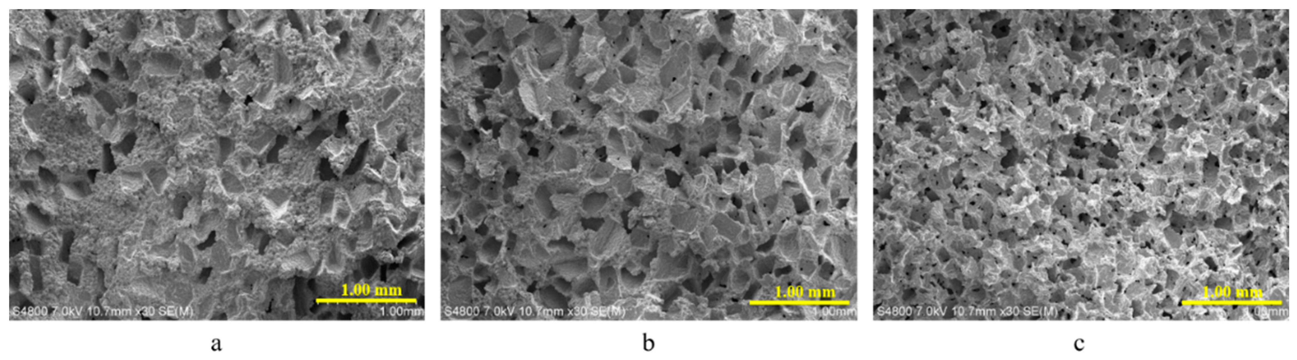
3.1. Morphology of Porous Structures

The pore morphology of the MIM fabricated porous stainless-steel structure was induced by the size and shape of the used space holder material crystals (sodium chloride). The spaces occupied by the NaCl crystals during the injection molding phase were converted into pores during the debinding phase once NaCl was removed from the samples. Figure 1 shows the SEM images of the sintered samples with different porosities of 10, 20, and 30 wt.%. The sintered, coin-shaped samples were broken in half mechanically, and the internal pore structure at the cross-sectional fracture plane was investigated and imaged with SEM. Increase in the NaCl content clearly increases the porosity of the sintered samples. The sample with the highest porosity (Figure 1c) has a highly porous structure with interconnected pores that extend deep into the structure. By comparison, the cross-sectional fracture surfaces of the samples with lower porosities were more closed and the number of small pores in the sample was lower (Figure 1a,b).

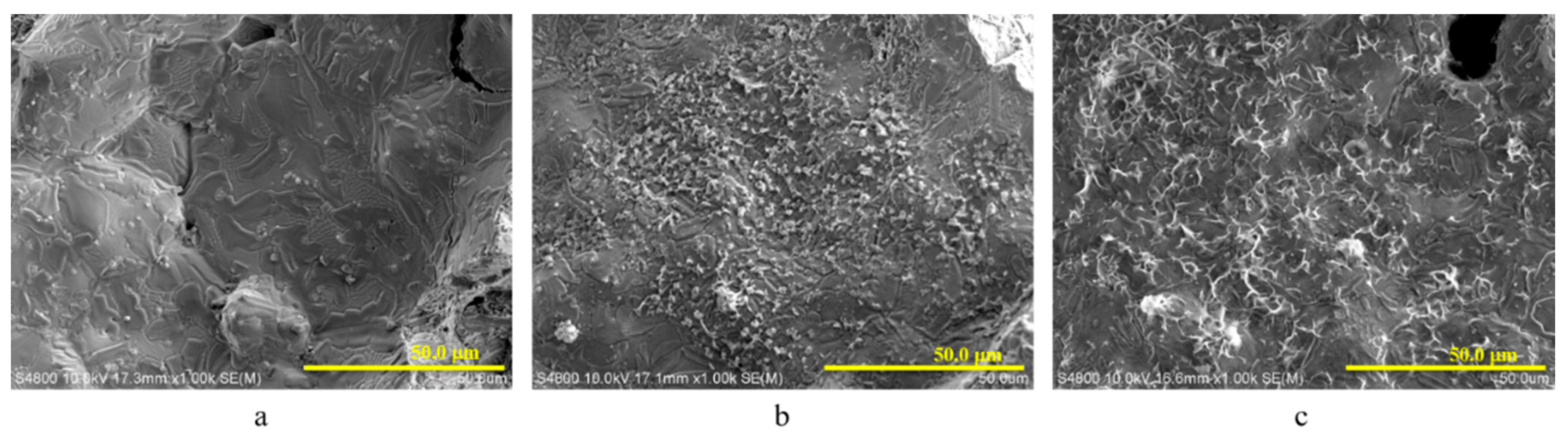
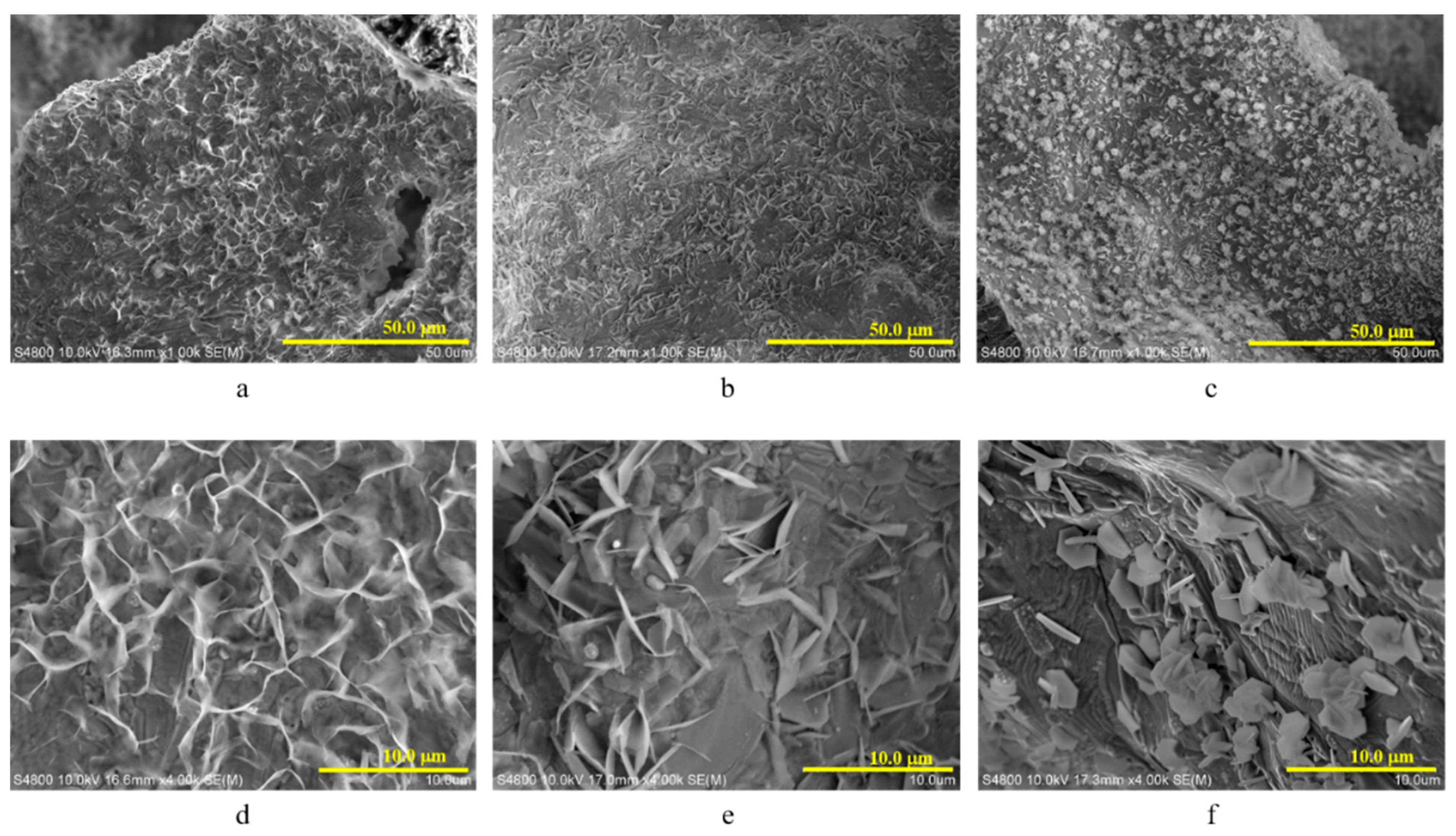
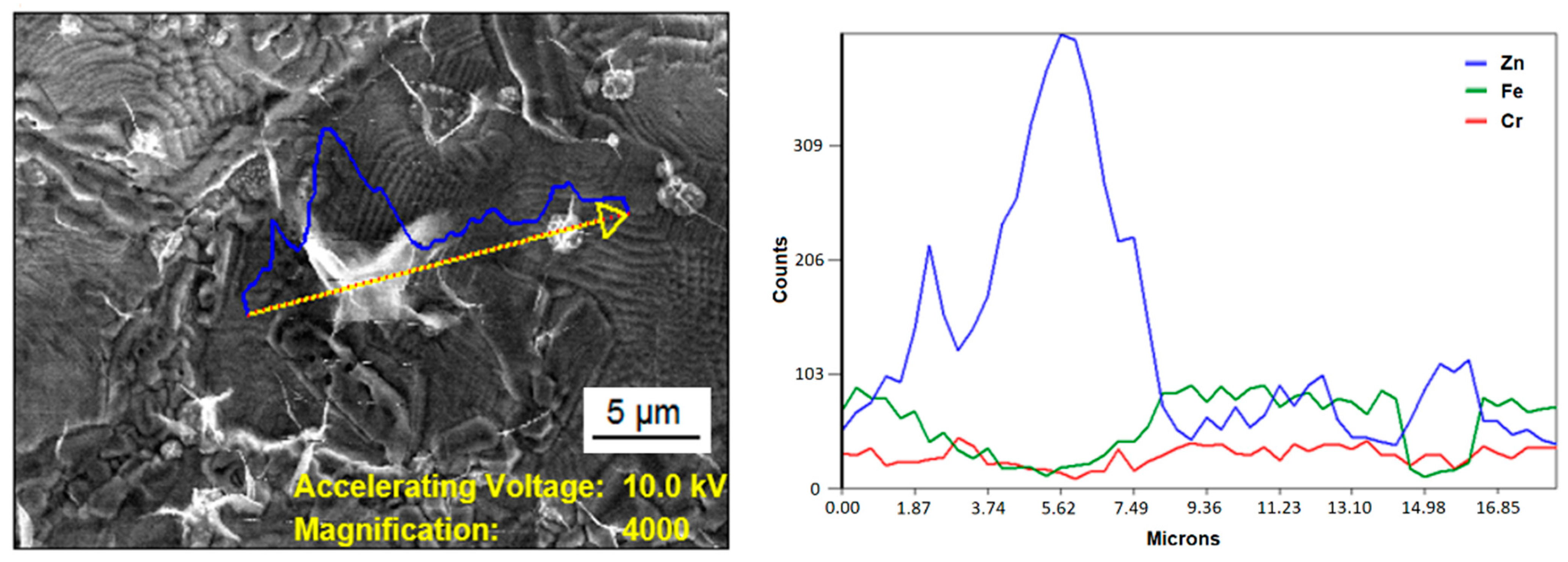
3.2. Morphology of the Electroplated Zinc Coating

Three different zinc electrolytes were used for electroplating from which zinc acetate was observed to possess better corrosion resistance than zinc sulfate or zinc chloride samples. Therefore, zinc acetate was used for electrolytic zinc deposition for all different porosities (10, 20, and 30 wt.% NaCl), whereas zinc chloride and zinc sulfate were used with the most porous sample (30 wt.% NaCl).
Figure 2 shows SEM images of the internal pore structure of samples with different porosities after electrochemical zinc deposition using zinc acetate. No zinc was observed inside the sample with the lowest porosity ((10 wt.% NaCl) in Figure 2a). This was probably due to a limited open porosity on the sample surface. No significant differences were observed in the deposited zinc amount either inside 20 wt.% (Figure 2b) or 30 wt.% (Figure 2c) samples. However, there was a clear difference in the deposited zinc morphology between the samples: the 20 wt.% sample had zinc deposits in more agglomerated form with small clusters, whereas the 30 wt.% sample contained a more web-like pattern with elongated shapes.
Figure 3 shows the SEM images of the internal pore structure of the 30 wt.% NaCl samples with zinc acetate (Figure 3a,d), zinc sulfate (Figure 3b,e), and zinc chloride (Figure 3c,f) as an electrolyte. The top row in Figure 3a–c can be used to evaluate the deposited zinc amount inside the samples. It is noteworthy that SEM images only capture a limited area of the entire sample. However, based on a thorough SEM analysis also displayed in Figure 3, it can be concluded that zinc acetate resulted in a lower deposited zinc amounts compared to the other two electrolytes. The deposited zinc amount was highest with zinc chloride electrolyte.
There is a clear difference in the deposited zinc morphology depending on the used electrolyte, as shown in the high magnification SEM images in Figure 3d–f. The deposited zinc does not form crystals with sharp edges using zinc acetate (Figure 3d), whereas the deposited crystals are thin, leaf-like, and more regular in shape and size with zinc sulfate (Figure 3e). The most regular crystal shapes were achieved with zinc chloride electrolyte (Figure 3f) having thin and hexagonal shaped crystals.
The observed differences both in quantity and quality of the deposited zinc may originate from the differences in the electric current during electrolysis with different electrolytes. For reproducibility and comparability of each test, the power supply was operated in a constant voltage mode at 2.0 V. The other parameters, such as the distance between the anode and cathode and the electrolyte concentration, were kept constant. It can be concluded that the varying morphologies resulted from the differences in electrolyte compounds as observed in the varying electric current during the electrolysis from around 0.04 A for zinc acetate to 0.05 A for zinc sulfate and 0.08 A for zinc chloride. A higher electrical conductivity of the zinc chloride electrolyte resulted in the observed higher amount of electrodeposited zinc. This is in agreement with the literature [36] as coarse crystals of zinc were obtained from acid sulfate solution electrodeposition, and even coarser crystals resulted from electroplating with chloride solution.
As a general remark, a regional variation in the shape and size of the zinc deposits, as well as the quantity of deposited zinc, was observed irrespective of the used electrolyte. Typically, a larger deposited zinc amount was observed closer to the sample surface where the electric field was the greatest. It is also important to note that in all cases the pores and cavities were not completely filled with zinc. However, the steel surface, even inside the samples, was coated with zinc deposits with varying thicknesses and amounts.
Figure 4 shows an EDS analysis of the deposited zinc inside a porous 440C stainless steel sample (30 wt.% NaCl) in the form of an X-ray line scan with zinc acetate electrolyte. The amount of zinc (blue) was compared to the amount of iron (green) and chromium (red). The curve of zinc coincides with the occurrence of the white structures in the secondary electron image of the sample. Thus, EDS analysis confirmed that the observed white flakes inside the samples were zinc. It is also worth emphasizing the presence of zinc throughout the scanned line in smaller amounts, which demonstrates the deposition of zinc over the entire surface as a thin layer. In addition, the oxygen signals in the EDS analysis were observed to coincide with the zinc peaks, which suggests the deposition of zinc as an oxide into the structure. It is known from the EDS analysis literature that the nominal difference between O Kα and Cr Lα peaks is only 51 eV, and thus the overlap of these peaks may result in the incorrect detection of oxygen in the sample by the detector. For the sake of clarity, the oxygen peaks are not displayed in Figure 4 as the main emphasis was to verify zinc deposition into the structure.

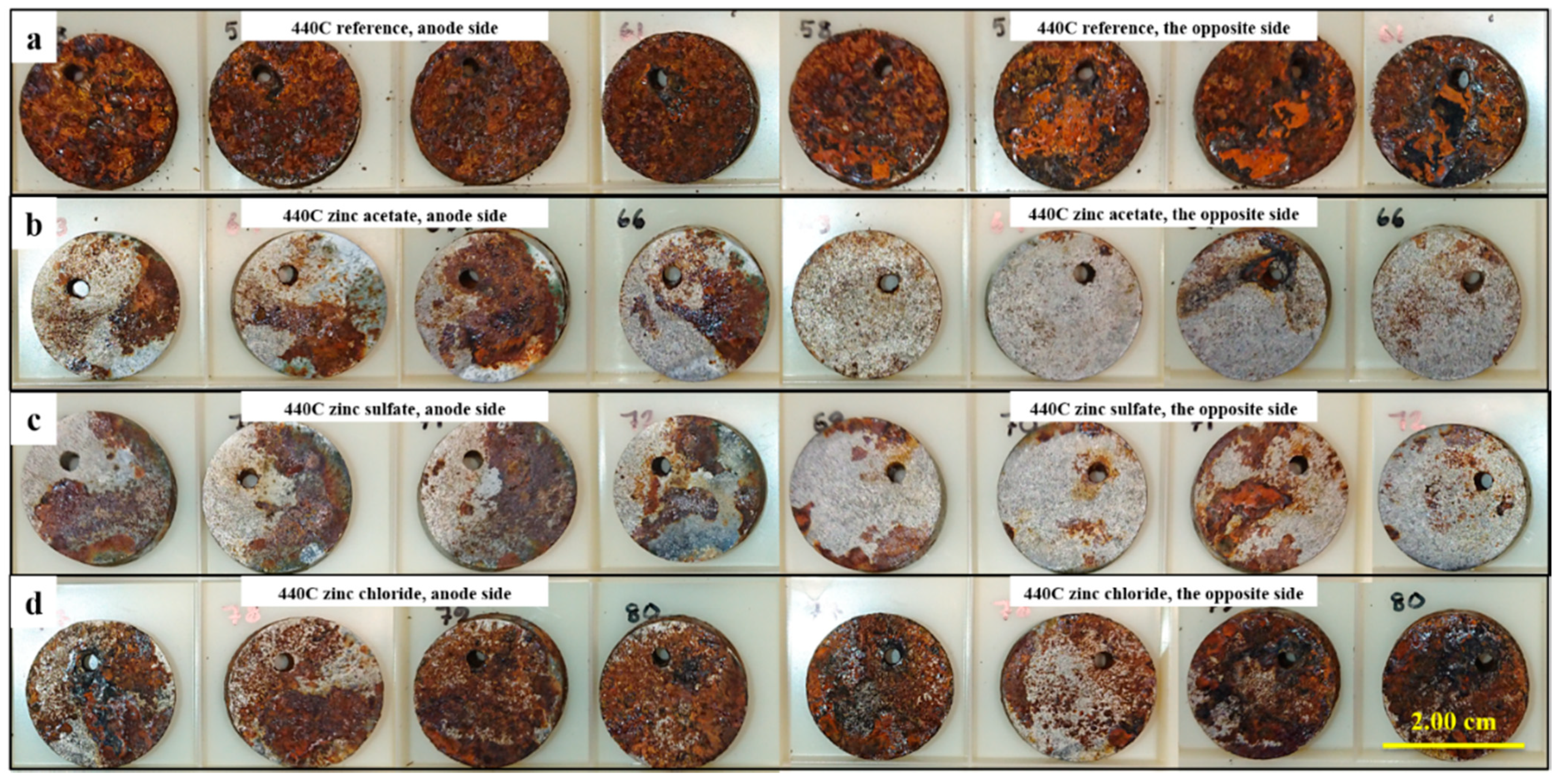
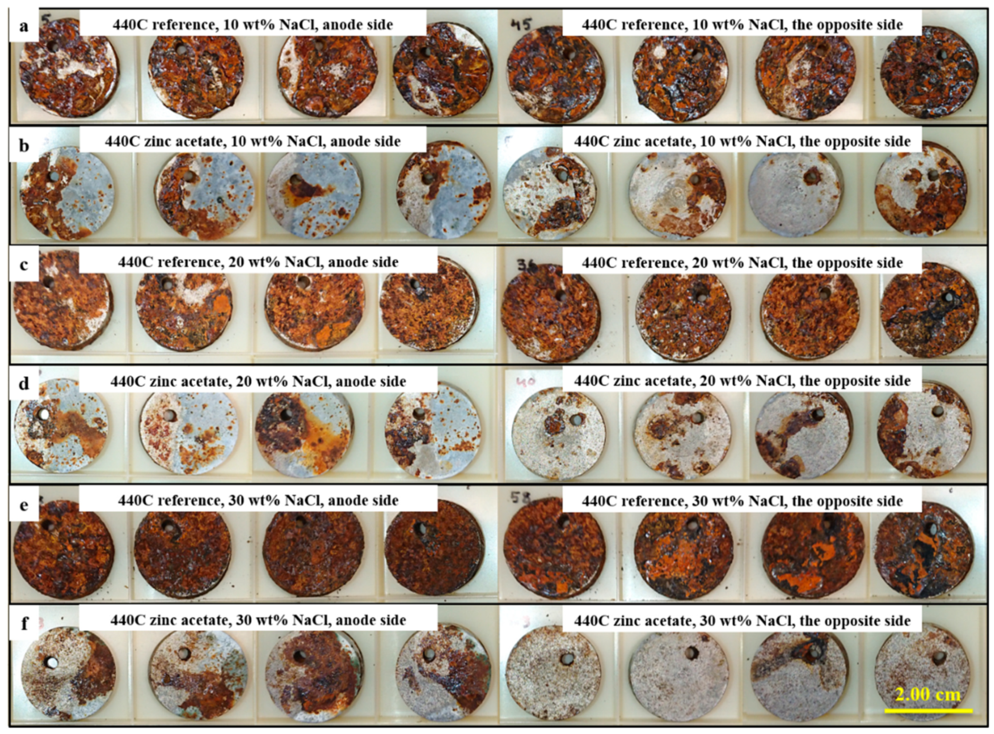
3.3. Corrosion Testing

Figure 5 shows the images of the 30 wt.% porosity samples after the corrosion test in neutral salt spray for the duration of 240 h. The effect of electrolyte composition on pitting corrosion behavior can be clearly observed. Each row shows four parallel samples from both sides with different electrolytes. The left half of each row, i.e., the first four images on each row displays the side of the samples that faced the zinc anode during electrolysis. On the right side are the same samples from the different side. The reference 440C samples without zinc plating on the top row (Figure 5a) display significant corrosion. A significant improvement in corrosion resistance was observed with the electroplated samples. The lowest corrosion was observed for zinc acetate (Figure 5b) and zinc sulfate (Figure 5c), whereas zinc chloride electrolyte (Figure 5d) displayed extensive corrosion on both sides of the sample. This was expected due to the corrosive nature of the acidic chloride electrolyte [36]. The highly corrosive environment of the electrolysis bath and the corrosion prone grade 440C stainless steel caused observable corrosion in the samples after electrolysis and before the salt spray testing. This initial corrosion explains the observed extensive corrosion of zinc chloride samples in the salt spray test despite the larger deposited zinc amount compared to the zinc acetate and zinc sulfate samples.
In summary, zinc coating improved pitting corrosion resistance for each sample compared to the reference. It is noteworthy that the side facing away from the zinc anode (labeled opposite side on the right side of b and c) corroded significantly less than the side facing the zinc anode (labeled anode side on the left side of b and c). This may be due to the electrolyte bath setup, i.e., the size and shape of the used beaker in electrolysis and the mixing speed may have had an effect on the uniformity of the zinc plating.
Finally, Figure 6 shows the effect of porosity on corrosion behavior. Porosities of 10 wt.% (Figure 6a,b), 20 wt.% (Figure 6c,d), and 30 wt.% (Figure 6e,f) wt.% of NaCl were used to create different porosities, and zinc electrodepositions (Figure 6b,d,f) were carried out by using zinc acetate electrolyte. Reference 440C samples displayed heavy corrosion on both sides, as shown in Figure 6a,c,e (similar to Figure 5). For all porosities, the zinc coating improved corrosion resistance compared to the reference 440C. However, no significant differences in corrosion resistance were observed between different porosities with zinc coated samples. For lower porosities shown in Figure 6b,d, the differences in corrosion between the two sides of the samples were not as large as in the case of the highest porosity (Figure 6f).

4. Conclusions

Porous injection molded 440C stainless steel structures were fabricated by using the PSH technique, and the internal pore structure was electrochemically deposited with corrosion protective zinc by three different electrolyte compositions of zinc acetate, zinc sulfate, and zinc chloride. The used electrolyte solution was observed to have a significant effect on the morphology and the amount of the deposited zinc inside the pore structure. The most regular zinc crystals and the thickest coating were observed with zinc chloride, whereas the lowest deposited zinc amount with the most irregular zinc crystals was observed with zinc acetate.
The objective of this study was to demonstrate a cathodic corrosion protection of injection molded porous 440C stainless steel structures by electroplating zinc into the pores. Corrosion protection was achieved by zinc coating of 440C stainless steel samples. It can be concluded that electrodeposition from zinc acetate electrolyte resulted in the highest pitting corrosion resistance. On the contrary, zinc chloride resulted in the weakest corrosion protection. The porosity of the samples was not observed to have a significant effect on corrosion resistance. It is believed that the results observed here can be applied to enhance the corrosion protection of stainless-steel grades. Furthermore, it is expected that zinc plating incorporated into the pore structure of porous stainless-steel materials may enable the use of such porous structures in more corrosive and environmentally harsh conditions in the future.

Author Contributions

M.K.: investigation and writing—original draft; K.M.: conceptualization, funding acquisition, project administration, and resources; J.J.S.: conceptualization, project administration, supervision, and writing—review and editing; M.S.: conceptualization, funding acquisition, project administration, resources, supervision, and writing—review and editing. All authors have read and agreed to the published version of the manuscript.

Funding

This research was funded by the Business Finland/ERDF (European Regional Development Fund) project “MIM Components for Harsh Conditions” (Grant agreement 7929/31/2019) for financial support. J.J.S. acknowledges the Faculty of Science and Forestry at the University of Eastern Finland for financial support (grant no. 579/2017) and the Academy of Finland Flagship for Photonics Research and Innovation (PREIN, decision no. 320166).

Institutional Review Board Statement

Not applicable.

Informed Consent Statement

Not applicable.

Data Availability Statement

The data presented in this study are available in article here. The data presented in this study are also available upon request from the corresponding author.

Conflicts of Interest

The authors declare no conflict of interest.

References

  1. Lo, K.H.; Shek, C.H.; Lai, J.K.L. Recent developments in stainless steels. Mater. Sci. Eng. R. Rep. 2009, 65, 39–104. [Google Scholar] [CrossRef]
  2. Huang, K.T.; Chang, S.H.; Wang, C.K.; Chen, J.K. Microstructures and mechanical properties of 440C stainless steel strengthened with TaC via vacuum sintering and heat treatments. Mater. Trans. 2015, 56, 1585–1590. [Google Scholar] [CrossRef] [Green Version]
  3. Lo, K.H.; Cheng, F.T.; Man, H.C. Laser transformation hardening of AISI 440C martensitic stainless steel for higher cavitation erosion resistance. Surf. Coat. Technol. 2003, 173, 96–104. [Google Scholar] [CrossRef]
  4. Lippold, J.C. Welding Metallurgy and Weldability; John Wiley & Sons: Hoboken, NJ, USA, 2015. [Google Scholar]
  5. Huang, K.T.; Chang, S.H.; Hsieh, P.C. Microstructure, mechanical properties and corrosion behavior of NbC modified AISI 440C stainless steel by vacuum sintering and heat treatments. J. Alloys Compd. 2017, 712, 760–767. [Google Scholar] [CrossRef]
  6. Salleh, S.H.; Omar, M.Z.; Syarif, J.; Ghazali, M.J.; Abdullah, S.; Sajuri, Z. Investigation of microstructures and properties of 440C martensitic stainless steel. Int. J. Mech. Mater. Eng. 2009, 4, 123–126. [Google Scholar]
  7. Puli, R.; Ram, G.D.J. Microstructures and properties of friction surfaced coatings in AISI 440C martensitic stainless steel. Surf. Coat. Technol. 2012, 207, 310–318. [Google Scholar] [CrossRef]
  8. Kwok, C.T.; Lo, K.H.; Cheng, F.T.; Man, H.C. Effect of processing conditions on the corrosion performance of laser surface-melted AISI 440C martensic stainless steel. Surf. Coat. Technol. 2003, 166, 221–230. [Google Scholar] [CrossRef]
  9. Antunes, P.D.; Correa, E.O.; Barbosa, R.P.; Silva, E.M.; Padilha, A.F.; Guimaraes, P.M. Effect of weld metal chemistry on stress corrosion cracking behavior of AISI 444 ferritic stainless steel weldments in boiling chloride solution. Mater. Corros. 2013, 64, 415–421. [Google Scholar] [CrossRef]
  10. Wang, Z.; Di-Franco, F.; Seyeux, A.; Zanna, S.; Maurice, V.; Marcus, P. Passivation-induced physicochemical alterations of the native surface oxide film on 316L austenitic stainless steel. J. Electrochem. Soc. 2019, 166, C3376–C3388. [Google Scholar] [CrossRef]
  11. Punckt, C.; Bölscher, M.; Rotermund, H.H.; Mikhailov, A.S.; Organ, L.; Budiansky, N.; Scully, J.R.; Hudson, J.L. Sudden onset of pitting corrosion on stainless steel as a critical phenomenon. Science 2004, 305, 1133–1136. [Google Scholar] [CrossRef]
  12. Ryan, M.P.; Williams, D.E.; Chater, R.J.; Hutton, B.M.; McPhail, D.S. Why stainless steel corrodes. Nature 2002, 415, 770–774. [Google Scholar] [CrossRef]
  13. Marcelin, S.; Pébère, N.; Régnier, S. Electrochemical investigations on crevice corrosion of a martensitic stainless steel in a thin-layer cell. J. Electroanal. Chem. 2015, 737, 198–205. [Google Scholar] [CrossRef] [Green Version]
  14. Dalmau, A.; Richard, C.; Igual-Muñoz, A. Degradation mechanisms in martensitic stainless steels: Wear, corrosion and tribocorrosion appraisal. Tribol. Int. 2018, 121, 167–179. [Google Scholar] [CrossRef]
  15. Parsapour, A.; Khorasani, S.N.; Fathi, M.H. Effect of Surface Treatment and Metallic Coating on Corrosion Behavior and Biocompatibility of Surgical 316L Stainless Steel Implant. J. Mater. Sci. Technol. 2012, 28, 125–131. [Google Scholar] [CrossRef]
  16. González, M.B.; Saidman, S.B. Electrodeposition of polypyrrole on 316L stainless steel for corrosion prevention. Corros. Sci. 2011, 53, 276–282. [Google Scholar] [CrossRef]
  17. Tan, Y.; Xu, Y.; Zhang, H.; Sun, C.; Liang, K.; Zhang, S. Pulse electroplating of ultra-fine grained zinc coating on 316L stainless steel and its corrosion behaviour. Int. J. Electrochem. Sci. 2016, 14, 5913–5922. [Google Scholar] [CrossRef]
  18. Zhao, X.; Han, L.; Xiao, J.; Wang, L.; Liang, T.; Liao, X. Corrosion protection of steel elements in façade systems. Sci. Total Environ. 2020, 32, 135938. [Google Scholar] [CrossRef]
  19. Li, Q.; Zeng, D.; An, M. Elevating the photo-generated cathodic protection of corrosion product layers on electrogalvanized steel through nano-electrodeposition. Chem. Phys. Lett. 2019, 722, 1–5. [Google Scholar] [CrossRef]
  20. Schlesinger, M.; Paunovic, M. Modern Electroplating, 5th ed.; John Wiley & Sons Inc.: Hoboken, NJ, USA, 2011. [Google Scholar]
  21. Xu, M.; Lam, C.N.C.; Wong, D.; Asselin, E. Evaluation of the cathodic disbondment resistance of pipeline coatings—A review. Prog. Org. Coat. 2020, 146, 105728. [Google Scholar] [CrossRef]
  22. Gomes, A.; Da Silva Pereira, M.I. Pulsed electrodeposition of Zn in the presence of surfactants. Electrochim. Acta 2006, 51, 1342–1350. [Google Scholar] [CrossRef]
  23. Chen, L.J.; Li, T.; Li, Y.M.; He, H.; Hu, Y.H. Porous titanium implants fabricated by metal injection molding. Trans. Nonferr. Met. Soc. China (Engl. Ed.) 2009, 19, 1174–1179. [Google Scholar] [CrossRef]
  24. Dehghan-Manshadi, A.; Yu, P.; Dargusch, M.; StJohn, D.; Qian, M. Metal injection moulding of surgical tools, biomaterials and medical devices: A review. Powder Technol. 2020, 364, 189–204. [Google Scholar] [CrossRef]
  25. Nishiyabu, K.; Matsuzaki, S.; Tanaka, S. Fabrication of micro porous metal components by metal injection molding based powder space holder method. High Temp. Mater. Process. 2007, 26, 257–267. [Google Scholar] [CrossRef]
  26. Gülsoy, H.Ö.; German, R.M. Production of micro-porous austenitic stainless steel by powder injection molding. Scr. Mater. 2008, 58, 295–298. [Google Scholar] [CrossRef]
  27. Manonukul, A.; Muenya, N.; Léaux, F.; Amaranan, S. Effects of replacing metal powder with powder space holder on metal foam produced by metal injection moulding. J. Mater. Process. Technol. 2010, 210, 529–535. [Google Scholar] [CrossRef]
  28. Li, D.; Hou, H.; Liang, L.; Lee, K. Powder injection molding 440C stainless steel. Int. J. Adv. Manuf. Technol. 2010, 49, 105–110. [Google Scholar] [CrossRef] [Green Version]
  29. Harun, W.; Toda, K.; Osada, T.; Kang, H.; Tsumori, F.; Miura, H. Effect of MIM Processing Parameters on the Properties of 440C Stainless Steel. J. Jpn. Soc. Powder Powder Metall. 2012, 59, 264–271. [Google Scholar] [CrossRef] [Green Version]
  30. García, C.; Martín, F.; de Tiedra, P.; Cambronero, L.G. Pitting corrosion behaviour of PM austenitic stainless steels sintered in nitrogen-hydrogen atmosphere. Corros. Sci. 2007, 49, 1718–1736. [Google Scholar] [CrossRef]
  31. Leisner, P.; Leu, R.C.; Møller, P. Electroplating of porous PM compacts. Powder Metall. 1997, 40, 207–210. [Google Scholar] [CrossRef]
  32. Seah, K.H.W.; Thampuran, R.; Teoh, S.H. The influence of pore morphology on corrosion. Corros. Sci. 1998, 40, 547–556. [Google Scholar] [CrossRef]
  33. Garcia-Cabezon, C.; Garcia-Hernandez, C.; Rodriguez-Mendez, M.L.; Martin-Pedrosa, F. A new strategy for corrosion protection of porous stainless steel using polypyrrole films. J. Mater. Sci. Technol. 2020, 37, 85–95. [Google Scholar] [CrossRef]
  34. Heaney, D.F. Handbook of Metal Injection Molding, 1st ed.; Woodhead Publishing Limited: Cambridge, UK, 2012. [Google Scholar]
  35. Gibson, L.J.; Ashby, M. Cellular Solids: Structure and Properties, 2nd ed.; Cambridge University Press: Cambridge, UK, 1999. [Google Scholar]
  36. Winand, R. Electrodeposition of Zinc and Zinc Alloys. In Modern Electroplating, 5th ed.; Schlesinger, M., Paunovic, M., Eds.; John Wiley & Sons Inc.: Hoboken, NJ, USA, 2011; pp. 285–307. [Google Scholar]
Figure 1. Low magnification SEM images of the internal pore structure of sintered 440C stainless steel samples. The amount of NaCl is 10 wt.% (a), 20 wt.% (b), and 30 wt.% (c).
Coatings 11 00949 g001
Figure 2. SEM images of the internal pore structure of sintered 440C stainless steel samples after zinc acetate electrodeposition. The amount of NaCl is 10 wt.% (a), 20 wt.% (b), and 30 wt.% (c).
Coatings 11 00949 g002
Figure 3. High magnification SEM images of the internal pore structure of sintered 440C stainless steel samples after zinc electrodeposition. The amount of NaCl is 30 wt.% in all images. The electrolytes used in the electrodeposition process are zinc acetate (a,d), zinc sulfate (b,e), and zinc chloride (c,f).
Coatings 11 00949 g003
Figure 4. SEM-EDS line scan (along the yellow dashed line on the left image) chemical composition analysis (right image) inside a porous 440C stainless steel sample with 30 wt.% porosity and zinc acetate used as an electrolyte.
Coatings 11 00949 g004
Figure 5. Images of porous 440C stainless steel samples with 30 wt.% porosity after the 240 h corrosion test. References without zinc (a), zinc acetate electrolyte (b), zinc sulfate electrolyte (c), and zinc chloride electrolyte (d) are displayed from both sides (the anode side and the opposite side relative to the anode) of the sample.
Coatings 11 00949 g005
Figure 6. Images of porous 440C stainless steel samples with varying porosity of 10 wt.% (a,b), 20 wt.% (c,d), and 30 wt.% (e,f) after the 240 h corrosion test. Reference samples without zinc (a,c,e) and the corresponding corrosion protected samples with zinc acetate electrolyte (b,d,f) are displayed with both sides (the anode side and the opposite side relative to the anode) of the sample. Images of the internal pore structure of the sintered 440C stainless steel samples. The amount of NaCl is 10 wt.% (a), 20 wt.% (b), and 30 wt.% (c).
Coatings 11 00949 g006
Table 1. Typical composition of PolyMIM 440C stainless steel (as sintered in % by weight).
CompositionFeCNiCrMoMnSiNbSP
> -0.85-16.0---1.0--
< Balance1.00.618.00.751.01.02.00.030.04
Table 2. Porous 440C sample masses before and after debinding.
NaCl (wt.%)Before Debinding (g)After Debinding (g)Mass Loss (%)
1012.62 ± 0.0810.90 ± 0.0813.6 ± 0.6
2011.33 ± 0.098.72 ± 0.0923.0 ± 0.5
3010.18 ± 0.106.82 ± 0.1333.0 ± 0.7
Publisher’s Note: MDPI stays neutral with regard to jurisdictional claims in published maps and institutional affiliations.

