Article

Effect of Vacuum Annealing on Microstructure and Hot-Salt Corrosion Behavior of CoNiCrAlY/YSZ/LaMgAl11O19 Double-Ceramic Coating

1
Liaoning Key Laboratory of Complex Workpiece Surface Special Machining, University of Science and Technology Liaoning, Anshan 114051, China
2
Equipment Manufacturing Department, Anshan Vocational and Technical College, Anshan 114020, China
3
Precision Forming Center, Southwest Technology and Engineering Research Institute, Chongqing 400039, China
*
Authors to whom correspondence should be addressed.
The authors contributed equally to this work.
Coatings 2021, 11(8), 951; https://doi.org/10.3390/coatings11080951
Submission received: 2 July 2021 / Revised: 4 August 2021 / Accepted: 6 August 2021 / Published: 9 August 2021
(This article belongs to the Special Issue Surface Modification and Functionalization for Advanced Materials)

Abstract

:
This study investigated the potential effect of vacuum annealing on the microstructure and hot salt corrosion behavior of CoNiCrAlY/YSZ/LaMgAl11O19 (LMA) double-ceramic coatings. A hot-salt corrosion test revealed that sprayed coatings exhibited an unsatisfactory anti-corrosion performance, and the LMA layer underwent severe fracture and corrosion degradation. Vacuum annealing induced a prominent recrystallization of the amorphous phase in LMA layer, triggering severe volume shrinkage and microcrack initiation. The recrystallization and volume shrinkage of the LMA layer were aggravated by an increase in the annealing temperature. The annealed coating with a higher fraction of the LaMA phase showed superior resistance to hot-salt corrosion. However, the salt mixture diffused simultaneously along the microcracks and eventually eroded into the YSZ layer. These results confirmed that vacuum annealing significantly enhanced the hot-salt corrosion resistance of the LMA layer. However, it deteriorated the barrier effect of the salt mixture through microcrack formation.

1. Introduction

In recent years, thermal barrier coatings (TBCs) have been widely used in the hot end components of aero-engines and gas turbines. The TBCs prepared by atmospheric plasma spraying (APS) or electron beam physical vapor deposition can significantly reduce the substrate temperature and improve the thermal efficiency of gas turbines [1,2,3,4,5]. A typical TBC system consists of a bonding layer and a ceramic top layer. The bonding layer protects the substrate from high-temperature oxidation corrosion and improves the bonding strength between the ceramic top layer and the substrate. The ceramic layer has a low thermal conductivity that effectively reduces the heat-transfer rate and allows the substrate to work within a tolerable range of temperatures [6,7,8,9,10,11,12].
Among the current TBC materials, yttria-stabilized zirconia (YSZ) has become the most widely used ceramic top-layer material because of its high melting point, low thermal conductivity, and high coefficient of thermal expansion. However, YSZ undergoes considerable phase change as the working temperature exceeds 1200 °C, triggering severe volume changes as well as stress cracking. In addition, the high oxygen conductivity of YSZ induces the formation of a thermally grown oxide between the YSZ and the bonding layer. This oxide can exacerbate the premature failure of the coating system [13,14,15,16]. Currently, YSZ coatings are unable to fulfill the growing need for the protection of hot end components during high-temperature service. Hence, it is essential to develop novel coating materials and structural designs for TBCs.
Rare-earth hexaaluminates, with a chemical composition of LnMgAl11O19 (Ln = La, Nd, or Gd), have high melting points, high thermal expansion coefficients, and low thermal conductivities [17,18,19,20,21,22,23]. These characteristics make them promising candidates for TBCs. Currently, LaMgAl11O19 (LMA) is the most widely studied rare-earth hexaaluminate. It was found that a YSZ/LMA double-ceramic structure had a longer service life than a single-layer YSZ or LMA during thermal cycling tests [24,25,26,27,28]. Additionally, the YSZ/LMA double-ceramic structure exhibited better corrosion resistance to molten salts such as V2O5, Na2SO4 + V2O5, and CAMS [29,30,31,32,33]. Sprayed LMA coatings contain high amounts of amorphous material because of the rapid cooling of molten particles. These coatings also experience recrystallization and volume shrinkage after high-temperature heat treatment. The recrystallization of the amorphous LaMA phase begins at ~900 °C. Two separate volume shrinkage processes occur in the LMA coating at 900 and 1200 °C. These are considered to transform the amorphous LaMA phase to the LaMA phase [18,25,34,35,36]. However, the influences of these two annealing temperatures on the microstructure and hot-salt corrosion behavior of the YSZ/LMA double-ceramic coating are still unclear. Here, CoNiCrAlY/YSZ/LMA double-ceramic coatings were prepared by APS and further annealed in vacuum at 900 and 1200 °C. The effects of vacuum annealing on the microstructure and hot-salt corrosion resistance of the sprayed and annealed coatings were investigated in detail.

2. Materials and Methods

GH199 superalloy was used as the substrate. The chemical composition of GH199 was 19.0–21.0 wt.% Co; 4.0–6.0 wt.% Mo; 9.0–11.0 wt.% W; 2.1–2.6 wt.% Al; 1.1–1.6 wt.% Ti; 0–4.0 wt.% Fe; 0–0.55 wt.% Si; 0–0.1 wt.% C; 0–0.5 wt.% Mn; 0–0.015 wt.% P; 0–0.015 wt.% S; 0–0.05 wt.% Mg; 0–0.008 wt.% B; and 0–0.07 wt.% Cu, with Ni as the balance. W, Mo, and Cr were added to the alloy for solid-solution strengthening. Al and Ti were added to form an aging strengthening phase; B and Mg were added to purify and strengthen the grain boundaries. Therefore, the alloy had high strength as well as good oxidation resistance and weldability, and the comprehensive performance of the alloy was satisfactory. The diameter and thickness of the samples prepared for the spraying test were 30 mm and 5 mm, respectively. All samples were sandblasted with corundum particles (240 mesh). CoCrNiAlY/YSZ/LMA dual-ceramic coatings were prepared by APS (MultiCoat, Oerlikon Metco). The spraying powders were CoCrNiAlY, YSZ, and LMA. The chemical composition of CoCrNiAlY was 31.0–34.0 wt.% Ni; 24.5–26.5 wt.% Cr; 5.0–6.5 wt.% Al; and 0.4–0.8 wt.% Y and Co was used as the balance. The chemical composition of YSZ was 7.0–7.5 wt.% and ZrO2 as balance. The chemical composition of LMA was 15.0–24.0 wt.% La2O3 and 4.0–7.0 wt.% MgO and Al2O3 was used as the balance. High-purity argon (99.9%) and hydrogen (99.9%) were used as the working gases. The spraying parameters of the CoCrNiAlY layer were 500 A (current) and 800 mm/min (line speed). The spraying parameters of the YSZ and LMA layers were 600 A and 800 mm/min, respectively. The sprayed samples were annealed in an industrial vacuum furnace. The samples were placed in an alumina crucible and transported to the heating area of the furnace. The annealing temperatures for the S1 and S2 samples were 900 and 1200 °C, respectively. When the pressure in the furnace was lower than 1 × 10⁻³ Pa, the furnace was filled with a protective gas (Ar), and the samples were heated to their respective annealing temperatures at a heating rate of 4 °C/min. Thereafter, the samples were annealed for 2 h at a constant temperature. The samples were cooled to the ambient temperature within the vacuum furnace itself to prevent contraction and cracking under the excessive stresses generated by rapid cooling and to suppress the influence of oxygen [37]. The annealing conditions are listed in Table 1. The sprayed sample S0 was used for comparison.
The hot-salt corrosion test was carried out in a muffle furnace (Shenyang Electric Furnace Factory, Shenyang, China). First, a 75 wt.% Na2SO4 + 25 wt.% NaCl supersaturated salt solution was evenly coated on the surface of the preheated coating samples. The salt mixture was repeatedly coated to ensure that 2–3 mg/cm2 of solid salt was deposited on the surface. Subsequently, the salt-mixture-coated samples were placed in an alumina crucible and heated in a muffle furnace at 900 °C for 3 h. The corroded samples were removed from the furnace, cooled to room temperature in air, and cleaned in boiling deionized water for 30 min. The cleaned samples were dried and weighed on an electronic balance with a sensitivity of 0.0001 g to determine the changes in their mass. The samples were then covered with a salt film again, and the above steps were repeated. The heating rate was less than 10 °C/min, and the total test time was 12 h. The phase compositions of all samples were investigated by X-ray diffraction (XRD, X’ Pert Powder, PANalytical B.V., Almelo, The Netherlands) by using a Cu-Kα radiation source with a scanning angle of 10–90° at a scanning rate of 8°/min. The surface and cross-sectional images of all samples were observed by using scanning electron microscopy (SEM, Zeiss ∑IGMA HD, Carl Zeiss, Jena, Germany). The microhardness of the NiCoCrAlY, YSZ, and LMA layers of each sample was measured using a Q10M microhardness tester (QNESS, Salzburg, Austria). The loading force was 0.98 N, and the full load time was 10 s. In order to reduce measurement errors, the averages of three measurement results for each layer were taken as the final measurement results.

3. Results

Figure 1 shows the XRD patterns of the sprayed and annealed coatings. The sprayed sample S0 was mainly composed of the LaMgAl11O19 (LaMA) phase. A number of bulges appeared in the XRD pattern. These were related to the high content of the amorphous phase in the sprayed LMA coating. Previous studies reported that since the LaMA phases are covered by the amorphous phase, they are difficult to detect by XRD, resulting in low diffraction intensity [36,38]. The change in the diffraction strength of the LaMA peak was minor, but the area of the amorphous bulge decreased significantly, indicating that recrystallization occurred in the LMA layer during vacuum annealing at 900 °C. Compared to the diffraction intensities exhibited by S0 and S1 in the LaMA phase, S2 exhibited a higher diffraction intensity, with the peaks matching the standard ICSD card 01-088-2135. LaMA phases were also detected in the LMA layer, indicating significant recrystallization during vacuum annealing at 1200 °C.
Figure 2 shows the surface and cross-sectional SEM images of the sprayed and annealed coatings. As shown in Figure 2a,b, the sprayed sample S0 exhibited a dense surface and cross-sectional texture without delamination or cracking, indicating good coating quality and density. However, the LMA layer in the annealed sample S1 showed a loose surface morphology (Figure 2c). Several microcracks were observed in its surface image, and the widths of the microcrack interfaces were as large as 5 μm in some cases. Meanwhile, visible longitudinal microcracks were apparent in the cross-sectional SEM image of the annealed sample S1 (Figure 2d), indicating prominent structural damage during 900 °C annealing. By contrast, the LMA layer of S2 experienced more serious fracture damage after 1200 °C annealing, as shown in Figure 2e,f. Several large longitudinal microcracks were observed in the surface and cross-sectional images, where some microcrack interface widths were as large as 10 μm.
The LMA layer experienced aggravated structural damage with an increase in the annealing temperature. This is attributed to the recrystallization of the amorphous phase. As identified by the XRD results in Figure 1, the visible bulges imply that a large fraction of the amorphous phase was formed in the sprayed LMA layer. The appearance of a large fraction of the LaMA phase in the LMA layer after vacuum annealing indicated significant amorphous recrystallization. According to previous studies [25,32], recrystallization induces significant volume shrinkage and generates local tensile stress; subsequent stress release further triggers the nucleation and expansion of microcracks in LMA layers. The current results clearly confirm that the LMA layer underwent severe recrystallization and volume shrinkage with increasing annealing temperature.
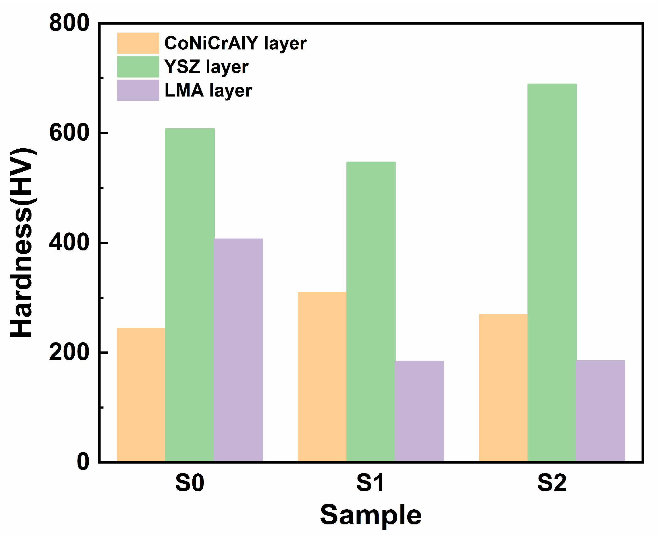
Figure 3 shows the average microhardness values of the sprayed and annealed coatings. The microhardness of the sprayed CoNiCrAlY layer was 244 HV. After vacuum annealing at 900 and 1200 °C, the microhardness values of the CoNiCrAlY layer increased to 309.5 and 269.6 HV, respectively. The increase in the microhardness of the CoNiCrAlY layer can be attributed to the decrease in porosity caused by the homogenization of the microstructure during vacuum annealing. Notably, the microhardness of the sprayed YSZ layer was 608.2 HV. After vacuum annealing at 900 °C, the microhardness of the YSZ layer decreased to 547 HV. After vacuum annealing at 1200 °C, the microhardness of the YSZ layer increased to 689.2 HV. This may be because the YSZ coating is prone to sintering at 1200 °C, which decreases the porosity of the coating. The microhardness of the sprayed LMA layer was 406.8 HV. After vacuum annealing at 900 and 1200 °C, the microhardness values of the LMA layer significantly decreased to 184 and 185 HV, respectively. From the cross-sectional and surface SEM images of the sprayed and annealed LMA layers, this decrease in microhardness can be attributed to the recrystallization of the amorphous phase. The recrystallization resulted in the formation of cracks in the LMA layer and significantly increased the porosity of the coating. Therefore, the porous structure caused by structural damage eventually decreased the microhardness of the LMA layer.
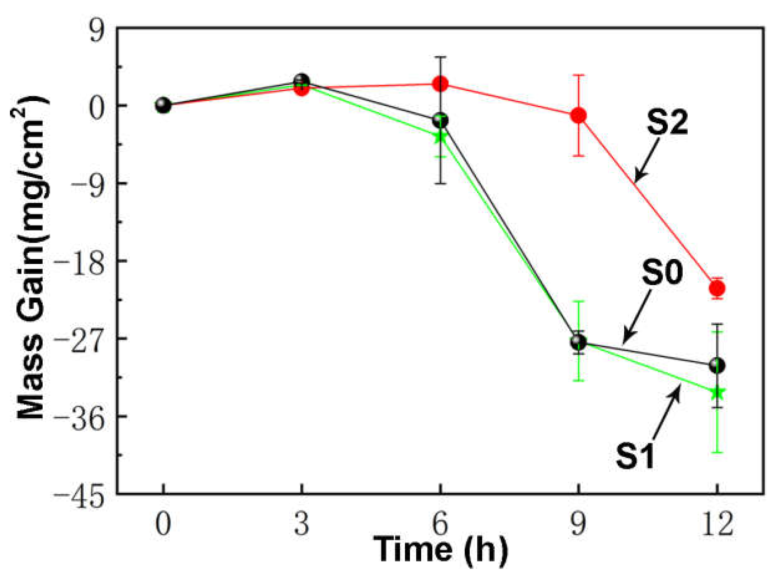
Figure 4 shows the corrosion kinetic curves of S0 (specimen without heat treatment), S1 (vacuum-annealed at 900 °C), and S2 (vacuum-annealed at 1200 °C) corroded in a 75% wt.% Na2SO4 + 25 wt.% NaCl molten salt mixture at 900 °C for 12 h. The change in the corrosion quality is a combined reflection of the formation of corrosion products, spalling, and dissolution. In the 12 h corrosion process, the mass of the three groups of samples first increased and then decreased significantly, indicating that all corrosion products underwent a certain degree of spalling. S0 and S1 exhibited similar corrosion kinetics curves. The S1 and S2 groups of samples were in a stage of weight gain at 2.75 mg/cm2 and 2.39 mg/cm2, respectively, before corrosion. Weight loss began at 3–12 h. After 12 h, the rates of mass loss for S1 and S2 were 30.16 mg/cm2 and 33.20 mg/cm2, respectively. For the 1200 °C vacuum-annealed specimen, a mass increase of 2.51 mg/cm2 occurred in the first 6 h of the test. During the 6–12 h weight loss stage, the mass loss was 21.18 mg/cm2. The corrosion kinetics curves of the three samples show that the 1200 °C vacuum-annealed sample exhibited the maximum resistance to hot corrosion, while the 900 °C vacuum-annealed sample exhibited an insignificant improvement over S0 in terms of the resistance towards hot corrosion.
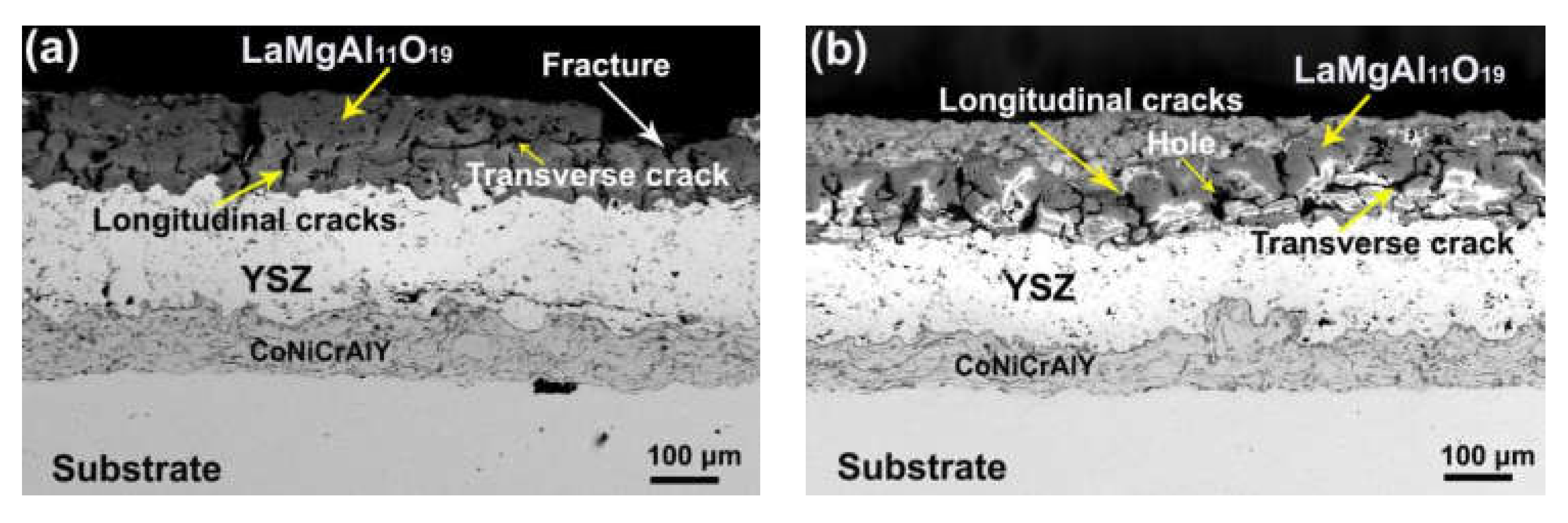
Figure 5 shows the cross-sectional SEM images of all coatings after the 6 h corrosion test. As shown in Figure 5a, the LMA layer of S0 underwent severe partial peeling. Several longitudinal cracks and long transverse cracks were apparent in the cross-sectional image, indicating that serious structural damage had occurred during the corrosion test. These transverse and longitudinal cracks also appeared in the LMA layers of S1, as shown in Figure 5b. The cracks in the corroded S1 were much larger compared to those in the annealed S1 (Figure 2b), which indicates aggravated structural damage during the corrosion test. By contrast, the corroded S2 presented a similar structure to that of the annealed S2. As shown in Figure 2c and Figure 5c, the sizes of the transverse and longitudinal cracks in the corroded LMA layer hardly changed in comparison to those in the annealed LMA layer.
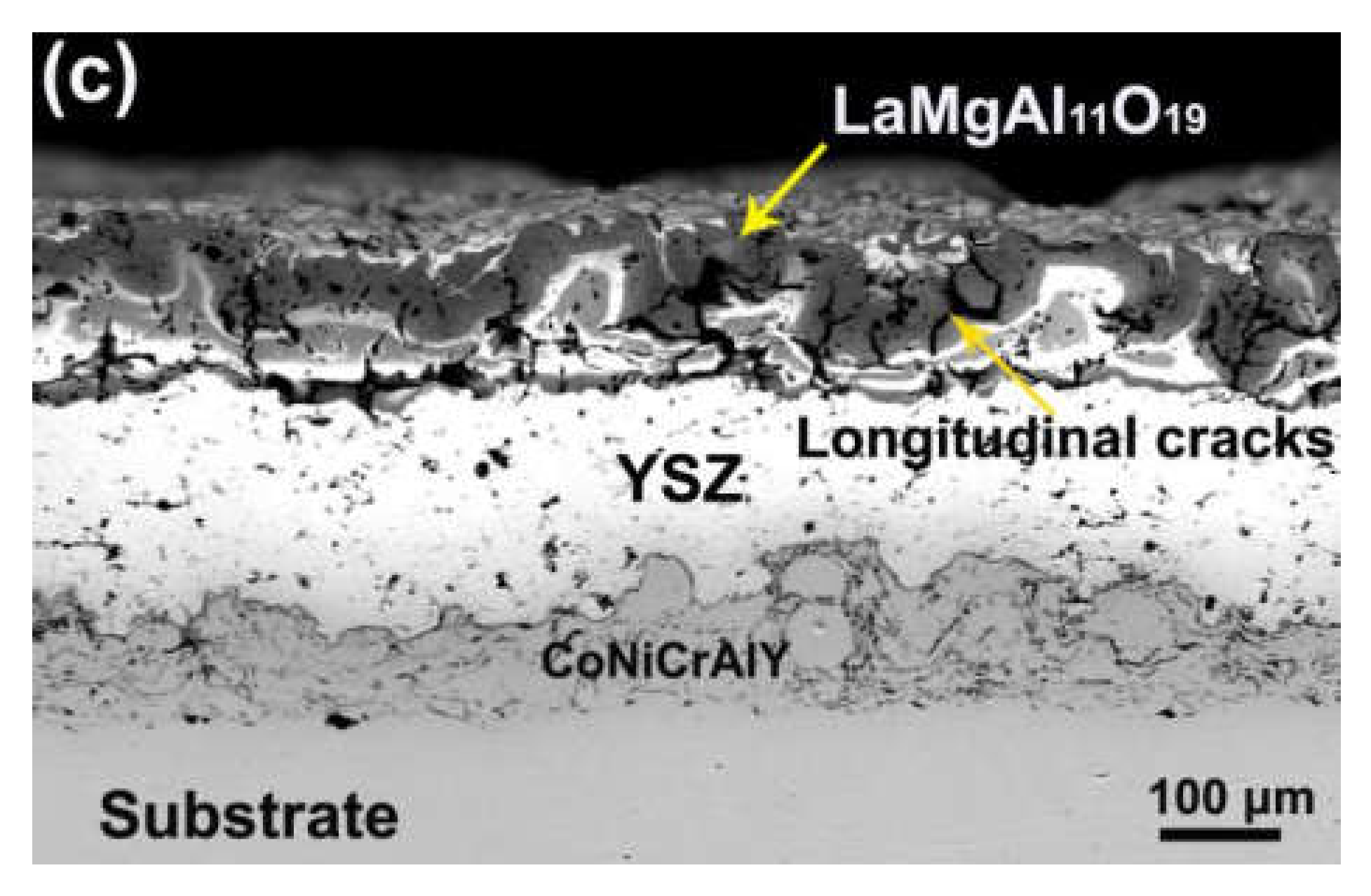
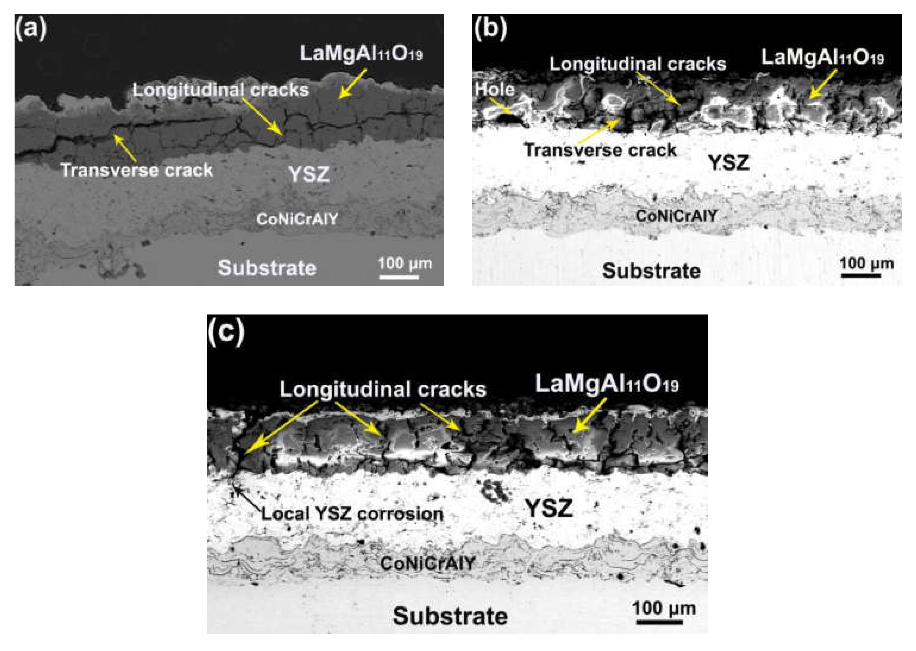
Figure 6 shows the cross-sectional SEM images of all coatings after the 12 h corrosion test. As shown in Figure 6a, the transverse cracks in the LMA layer of S0 extended and penetrated the entire LMA layer; some visible local dissolution of the LMA layer indicates that aggravated structural damage and corrosion degradation occurred during the corrosion test. The LMA layer of S1 also experienced severe local dissolution and structural damage during the corrosion test. As shown in Figure 6b, the transverse and longitudinal cracks in the LMA layer of S1 expanded and joined together, resulting in a significant increase in the porosity of the LMA layer. By contrast, the LMA layer of S2 exhibited slight dissolution and local damage during the corrosion test, which implies improved resistance to hot-salt corrosion. However, the longitudinal cracks in the LMA layer acted as diffusion channels of the corrosive salt mixture and aggravated the multi-scale intergranular corrosion. As shown in Figure 6c, a longitudinal crack extended to the YSZ layer and consequently resulted in serious corrosion between YSZ and the salt mixture.
Vacuum annealing affects the microstructure and hot-salt corrosion behavior of sprayed double-ceramic coatings. It has been reported that the melting point of a 75 wt.% Na2SO4 + 25 wt.% NaCl salt mixture is 645 °C. During the hot-salt corrosion test, Type-Ι hot corrosion occurred, and the salt mixture of Na2SO4 and NaCl decomposed at the interface of the molten salt and coating according to reaction Equations (1) and (2) [39].
Na2SO4 (s)→Na2O (s) + SO3 (g)→Na2O (s) + SO2 (g) + 1/2O2 (g),
2NaCl (s) + O2 (g) + SO2 (g)→Na2SO4 (s) + Cl2 (g).
The local alkalinity gradually increased with the decomposition of the molten salt. Na2O reacted with Al2O3, which resulted in alkaline dissolution according to reaction Equations (3) and (4).
Al2O3 + Na2O→2NaAlO2,
Na2+ + 2AlO2→NaAl2O4.
Meanwhile, the amorphous LMA further decomposed during the hot-salt corrosion test according to reaction Equation (5) [38].
LaMgAl11O19 (s)→LaAlO3 (s) + MgO (s) + 5Al2O3 (s).
Based on the XRD, corrosion kinetics, and SEM results, the sprayed LMA layer exhibited low hot-salt corrosion resistance, which can be attributed to the amorphous phases. As identified by the XRD results in Figure 1, a large fraction of amorphous phases formed in the sprayed LMA layer. During the hot-salt corrosion test, these amorphous phases triggered the formation of a large amount of Al2O3 according to Equation (5). These Al2O3 products further reacted with Na2O according to reaction (3), resulting in the serious corrosive degradation of the LMA layer. However, the improved resistance of the annealed LMA layer towards hot-salt corrosion was attributed to the significant recrystallization of the amorphous phase, as identified by the XRD results in Figure 1, followed by the formation of stable LaMA phases during vacuum annealing. It has been reported that the reaction of the LaMA phase with corrosive media is difficult [40]. Therefore, the formation of the LaMA phases improved the hot-salt corrosion resistance of these annealed coatings. Furthermore, the XRD results revealed that vacuum annealing at 1200 °C induced a more comprehensive recrystallization of the amorphous material than recrystallization at 900 °C. The large fraction of LaMA phases resulted in the appreciable corrosion resistance of S2. However, vacuum annealing also triggered severe volume shrinkage that resulted in the initiation of microcracks, as shown in Figure 5 and Figure 6. Furthermore, it accelerated the inward diffusion of the salt mixture, which resulted in an eventual degradation of the barrier effect of the LMA layer. For future engineering applications, it is essential to develop a feasible strategy to heal the microcracks in an annealed LMA layer.

4. Conclusions

This study investigated the microstructure and hot-salt corrosion behavior of sprayed and annealed CoNiCrAlY/YSZ/LMA double-ceramic coatings. The top LMA layer in the sprayed coating contained a large fraction of amorphous material that exhibited low resistance to hot-salt corrosion. Consequently, severe fractures and corrosive degradation were observed in the spray coating sample S0. By contrast, the top LMA layer of the annealed coating experienced aggravated recrystallization of the amorphous phase and volume shrinkage with increasing annealing temperature. The recrystallization of the amorphous phase induced the formation of the LMA phase, which improved the resistance of the vacuum-annealed coating toward corrosive degradation by the hot-salt mixture. Hence, the hot-corrosion resistance of the LMA layer improved upon vacuum annealing at 1200 °C. However, vacuum annealing also resulted in volume shrinkage, which resulted in the initiation of microcracks. These microcracks functioned as diffusion channels for the salt mixture, which resulted in the deterioration of the barrier effect of the LMA layer.

Author Contributions

Conceptualization, S.H. and Z.W.; methodology, Y.S.; investigation, G.X. and L.X.; supervision, Z.X. All authors have read and agreed to the published version of the manuscript.

Funding

This study was supported by the Southwest Institute of Technology and Engineering Cooperation fund (HDHDW5902020103), University of Science and Technology Liaoning Talent Project Grants (601011507-07).

Institutional Review Board Statement

Not applicable.

Informed Consent Statement

Not applicable.

Data Availability Statement

No new data were created or analyzed in this study. Data sharing is not applicable to this article.

Acknowledgments

We sincerely thank the Beijing Power Machinery Institute for the coating spraying.

Conflicts of Interest

The authors declare no conflict of interest.

References

  1. Clarke, D.; Levi, C. Materials design for the next generation thermal barrier coatings. Annu. Rev. Mater. Res. 2003, 33, 383–417. [Google Scholar] [CrossRef]
  2. Padture, N.P.; Gell, M.; Jordan, E.H. Thermal barrier coatings for gas-turbine engine applications. Science 2002, 296, 280–284. [Google Scholar] [CrossRef]
  3. Clarke, D.R.; Phillpot, S.R. Thermal barrier coating materials. Mater. Today 2005, 8, 22–29. [Google Scholar] [CrossRef]
  4. Vassen, R.; Stuke, A.; Stöver, D. Recent developments in the field of thermal barrier coatings. J. Therm. Spray Technol. 2009, 18, 181–186. [Google Scholar] [CrossRef]
  5. Stöver, D.; Pracht, G.; Lehmann, H. New material concepts for the next generation of plasma-sprayed thermal barrier coatings. J. Therm. Spray. Technol. 2004, 13, 76–83. [Google Scholar] [CrossRef]
  6. Cao, X.; Vaßen, R.; Stöver, D. Ceramic materials for thermal barrier coatings. J. Eur. Ceram. Soc. 2004, 24, 1–10. [Google Scholar] [CrossRef]
  7. Vaßen, R.; Jarligo, M.O.; Steinke, T.D.; Mack, E.; Stöver, D. Overview on advanced thermal barrier coatings. Surf. Coat. Technol. 2010, 205, 938–942. [Google Scholar] [CrossRef]
  8. Zhong, X.; Zhao, H.; Liu, C.; Wang, L.; Shao, F.; Zhou, X.; Tao, S.; Ding, C. Improvement in thermal shock resistance of gadolinium zirconate coating by addition of nanostructured yttria partially-stabilized zirconia. Ceram. Int. 2015, 41, 7318–7324. [Google Scholar] [CrossRef]
  9. Tsukada, S.; Kuroda, S.; Nishijima, M.; Araki, H.; Yumoto, A.; Watanabe, M. Effects of amorphous phase on hot corrosion behavior of plasma-sprayed LaMgAl11O19 coating. Surf. Coat. Technol. 2019, 363, 95–105. [Google Scholar] [CrossRef]
  10. Feuerstein, A.; Knapp, J.; Taylor, T. Technical and economical aspects of current thermal barrier coating systems for gas turbine engines by thermal spray and EBPVD: A review. J. Therm. Spray. Technol. 2008, 17, 199–213. [Google Scholar] [CrossRef]
  11. Miller, R.A. Current status of thermal barrier coatings—An overview. Surf. Coat. Technol. 1987, 30, 1–11. [Google Scholar] [CrossRef]
  12. Movchan, B.A. EB-PVD technology in the gas turbine industry: Present and future. JOM 1996, 48, 40–45. [Google Scholar] [CrossRef]
  13. Gao, L.H.; Guo, H.B.; Wei, L.Q. Microstructure and mechanical properties of yttria stabilized zirconia coatings prepared by plasma spray physical vapor deposition. Ceram. Int. 2015, 41, 8305–8311. [Google Scholar] [CrossRef]
  14. Hannink, R.H.J.; Kelly, P.M.; Muddle, B.C. Transformation toughening in zirconia-containing ceramics. J. Am. Ceram. Soc. 2000, 83, 416–487. [Google Scholar] [CrossRef]
  15. Liu, Z.G.; Ouyang, J.H.; Zhou, Y.; Li, J.; Xia, X.L. Influence of ytterbium-and samarium-oxides codoping on structure and thermal conductivity of zirconate ceramics. J. Eur. Ceram. Soc. 2009, 29, 647–652. [Google Scholar] [CrossRef]
  16. Withey, E.; Petorak, C.; Trice, R.; Dickinson, G.; Taylor, T. Design of 7 wt.% Y2O3–ZrO2/mullite plasma-sprayed composite coatings for increased creep resistance. J. Eur. Ceram. Soc. 2007, 27, 4675–4683. [Google Scholar] [CrossRef]
  17. Chen, X.; Zhao, Y.; Gu, L.; Zou, B.; Wang, Y.; Cao, X. Hot corrosion behaviour of plasma sprayed YSZ/LaMgAl11O19 composite coatings in molten sulfate–vanadate salt. Corros. Sci. 2011, 53, 2335–2343. [Google Scholar] [CrossRef]
  18. Sun, J.B.; Wang, J.S.; Dong, S.J. Effect of heat treatment on microstructure and property of plasma-sprayed lanthanum hexaaluminate coating. J. Compd. 2018, 739, 856–865. [Google Scholar] [CrossRef]
  19. Chen, H.; Gao, Y.; Tao, S. Thermophysical properties of lanthanum zirconate coating prepared by plasma spraying and the influence of post-annealing. J. Alloys Compd. 2009, 486, 391–399. [Google Scholar] [CrossRef]
  20. Bobzin, K.; Zhao, L.; Öte, M. Deposition and characterization of thermal barrier coatings of ZrO2–4 mol.% Y2O3–1 mol.% Gd2O3–1 mol.% Yb2O3. Surf. Coat. Technol. 2015, 268, 205–208. [Google Scholar] [CrossRef]
  21. Gadow, R.; Lischka, M. Lanthanum hexaaluminate—Novel thermal barrier coatings for gas turbine applications—Materials and process development. Surf. Coat. Technol. 2002, 151, 392–399. [Google Scholar] [CrossRef]
  22. Haoran, L.; Chang-An, W.; Chenguang, Z. Thermo-physical properties of rare-earth hexaaluminates LnMgAl11O19 (Ln: La, Pr, Nd, Sm, Eu and Gd) magnetoplumbite for advanced thermal barrier coatings. J. Eur. Ceram. Soc. 2015, 35, 1297–1306. [Google Scholar] [CrossRef]
  23. Wang, Y.H.; Liu, Z.G.; Ouyang, J.H. Preparation and thermophysical properties of LaMgAl11O19–Yb3Al5O12 ceramic composites. Ceram. Int. 2011, 37, 2489–2493. [Google Scholar] [CrossRef]
  24. Chen, X.L.; Zhang, J.F.; Zhang, Y.F. Thermal cycling behaviors of the plasma sprayed thermal barrier coatings of hexaluminates with magnetoplumbite structure. J. Eur. Ceram. Soc. 2010, 30, 1649–1657. [Google Scholar] [CrossRef]
  25. Sun, J.; Hui, Y.; Jiang, J. Crystallization mechanism of plasma-sprayed LaMgAl11O19 coating. Appl. Surf. Sci. 2020, 504, 144509. [Google Scholar] [CrossRef]
  26. Friedrich, C.; Gadow, R.; Schirmer, T. Lanthanum hexaaluminate—A new material for atmospheric plasma spraying of advanced thermal barrier coatings. J. Therm. Spray Technol. 2001, 10, 592–598. [Google Scholar] [CrossRef]
  27. Liu, H.Z.; Ouyang, J.H.; Liu, Z.G. Microstructure, thermal shock resistance and thermal emissivity of plasma sprayed LaMAl11O19 (M= Mg, Fe) coatings for metallic thermal protection systems. Appl. Surf. Sci. 2013, 271, 52–59. [Google Scholar] [CrossRef]
  28. Tarasi, F.; Medraj, M.; Dolatabadi, A. Thermal cycling of suspension plasma sprayed alumina-YSZ coatings containing amorphous phases. J. Am. Ceram. Soc. 2012, 95, 2614–2621. [Google Scholar] [CrossRef] [Green Version]
  29. Zeng, J.; Sun, J.; Zhang, H.; Yang, X.; Qiu, F.; Zhou, P.; Niu, W.; Dong, S.; Zhou, X.; Cao, X. Lanthanum magnesium hexaluminate thermal barrier coatings with pre-implanted vertical microcracks: Thermal cycling lifetime and CMAS corrosion behaviour. Ceram. Int. 2018, 44, 11472–11485. [Google Scholar] [CrossRef]
  30. Jana, P.; Jayan, P.S.; Mandal, S.; Biswas, K. Hot corrosion behaviour of rare-earth magnesium hexaaluminate based thermal barrier coatings under molten sulphatevanadate salts. Surf. Coat. Technol. 2017, 332, 108–119. [Google Scholar] [CrossRef]
  31. Chen, X.; Cao, X.; Zou, B.; Gong, J.; Sun, C. High-temperature corrosion behaviour of plasma sprayed lanthanum magnesium hexaluminate coating by vanadium oxide. J. Eur. Ceram. Soc. 2015, 35, 227–236. [Google Scholar] [CrossRef]
  32. Krämer, S.; Yang, J.; Levi, C.G. Thermochemical interaction of thermal barrier coatings with molten CaO–MgO–Al2O3–SiO2 (CMAS) deposits. J. Am. Ceram. Soc. 2006, 89, 3167–3175. [Google Scholar] [CrossRef]
  33. Cui, J.J.; Ouyang, J.H.; Liu, Z.G. Hot corrosion behavior of LaMgAl11O19 ceramic coated with molten CMAS deposits at temperature of 1250 °C in air. J. Alloys Comp. 2016, 685, 316–321. [Google Scholar] [CrossRef]
  34. Huang, L.L.; Meng, H.M.; Tand, J. Crystallization behavior of plasma-sprayed lanthanide magnesium hexaaluminate coatings. Int. J. Miner. Metall. Mater. 2014, 21, 1247–1253. [Google Scholar] [CrossRef]
  35. Sun, J.; Wang, J.; Zhou, J.X.; Dong, S.; Deng, L.; Jiang, J.; Cao, X. Microstructure and thermal cycling behavior of plasma-sprayed LaMgAl11O19 coatings. Ceram. Int. 2018, 44, 5572–5580. [Google Scholar] [CrossRef]
  36. Sun, J.; Wang, J.; Hao, Z.; Yuan, J.; Dong, S.; Jiang, J.; Deng, L.; Xin, Z.; Cao, X. Preparation, structure, mechanical properties and thermal cycling behavior of porous LaMgAl11O19 coating. J. Alloys Compd. 2018, 750, 1007–1016. [Google Scholar] [CrossRef]
  37. Meng, G.H.; Zhang, B.Y.; Liu, H. Vacuum heat treatment mechanisms promoting the adhesion strength of thermally sprayed metallic coatings. Surf. Coat. Technol. 2018, 344, 102–110. [Google Scholar] [CrossRef]
  38. Chen, X.; Zhao, Y.; Fan, X. Thermal cycling failure of new LaMgAl11O19/YSZ double ceramic top coat thermal barrier coating systems. Surf. Coat. Technol. 2011, 205, 3293–3300. [Google Scholar] [CrossRef]
  39. Liu, R.D.; Jiang, S.M.; Yu, H.J. Preparation and hot corrosion behaviour of Pt modified AlSiY coating on a Ni-based superalloy. Corros. Sci. 2016, 104, 162–172. [Google Scholar] [CrossRef]
  40. Chen, X.; Cao, X.; Zou, B.; Gong, J.; Sun, C. Corrosion of lanthanum magnesium hexaaluminate as plasma-sprayed coating and as bulk material when exposed to molten V2O5-containing salt. Corros. Sci. 2015, 91, 185–194. [Google Scholar] [CrossRef]
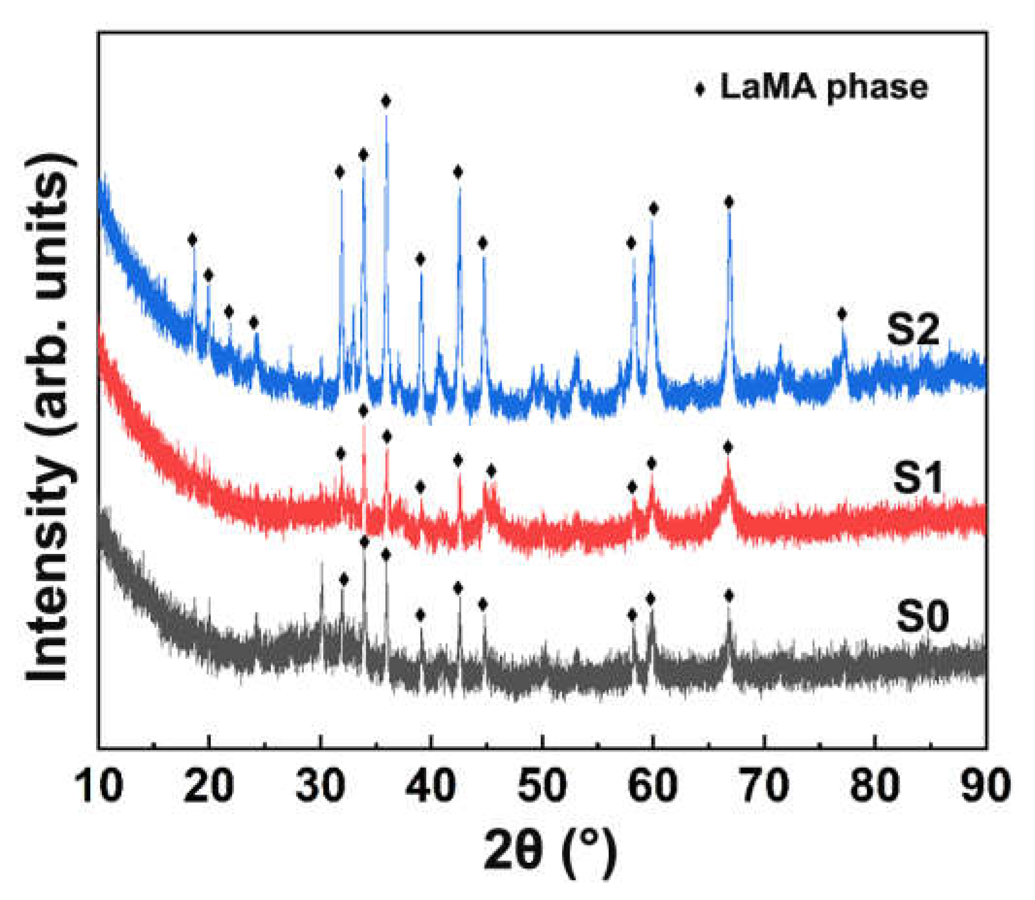
Figure 1. XRD patterns of the sprayed and annealed coatings.
Coatings 11 00951 g001
Figure 2. Surface and cross-sectional SEM images of sprayed and annealed coatings: (a,b) S0, (c,d) S1, and (e,f) S2.
Coatings 11 00951 g002
Figure 3. Average microhardness of the sprayed and annealed coatings.
Coatings 11 00951 g003
Figure 4. Corrosion kinetics of sprayed and annealed coatings.
Coatings 11 00951 g004
Figure 5. Cross-sectional SEM images of coatings after 6 h corrosion test: (a) S0, (b) S1, and (c) S2.
Coatings 11 00951 g005aCoatings 11 00951 g005b
Figure 6. Cross-sectional SEM images of coatings after 12 h corrosion test: (a) S0, (b) S1, and (c) S2.
Coatings 11 00951 g006
Table 1. Annealing parameters of sprayed coatings.
SampleAnnealing Temperature (°C)Time (h)
S19002
S212002
Publisher’s Note: MDPI stays neutral with regard to jurisdictional claims in published maps and institutional affiliations.