Article

Anti-Blocking Mechanism of Flocking Drainage Pipes in Tunnels Based on Mathematical Modeling Theory

1
College of Civil Engineering, Chongqing Jiaotong University, Chongqing 400074, China
2
State Key Laboratory of Mountain Bridge and Tunnel Engineering, Chongqing Jiaotong University, Chongqing 400074, China
*
Author to whom correspondence should be addressed.
Coatings 2021, 11(8), 961; https://doi.org/10.3390/coatings11080961
Submission received: 5 July 2021 / Revised: 11 August 2021 / Accepted: 11 August 2021 / Published: 13 August 2021
(This article belongs to the Special Issue Corrosion and Degradation of Materials)

Abstract

:
Crystalline pipe plugging in tunnel drainage systems is one of the causes of tunnel lining cracking and water leakage. Therefore, effective prevention of crystalline pipe blockage in tunnel drainage systems is very important to ensure the safety and stability of the lining structure during tunnel operation. Combined with the theories of fluid mechanics, structural mechanics and basic physics, the flocking and anti-blocking mechanism of drainage pipe was comprehensively analyzed by using the method of mathematical modeling, including: (1) the calculation expression of average velocity of the flocked section of a flocked drainage pipe v = Q/(C1  C2(r + r′)) and the calculation formula of flowing water pressure under the action of groundwater Fw =  KAγQ2/(2g(C1C2(r + r′))2); (2) the flow velocity v0 in the flocked drainage pipe shall meet v2 < 4gπrlτ1/γKA, crystals will be attached to the fluff and the crystals will maintain dynamic balance; (3) the flow velocity v0 in the flocked drainage pipe shall meet v2 ≥ 4gπrlτ1KA, crystals will not adhere to the fluff and the flocked drainage pipe will remain unobstructed. The research on the mechanism of preventing blockage of flocking drainage pipes fills the gap in research theory in this regard, contributes to the popularization and application of blocking prevention technology of flocking drainage pipes, reduces the maintenance cost during operation of tunnel drainage systems and ensures the safe and normal operation of tunnels.

1. Introduction

As of the end of 2020, there were 21,316 highway tunnels in China, including 1394 extra-long tunnels and 5541 long tunnels [1]. However, with the operation of the tunnels, various types of damage have gradually appeared, especially lining leakage (Figure 1) and cracking (Figure 2) caused by the crystallization-induced blockage of the drainage system of the tunnel in the karst area (Figure 3) [2], which seriously affects the safety of the tunnel lining. At present, a tunnel drainage system blockage caused by crystals can only be dredged by high-pressure gas (water) [3] or excavation, which is costly and affects the normal passage of the tunnel.
To make the lining structure of the tunnel safe and stable, it is necessary to ensure the effective and smooth operation of the drainage system of the tunnel. Therefore, it is necessary to prevent the occurrence of crystallization-induced pipe blockage in the drainage system in advance. In view of the problem of crystallization blockage in the tunnel drainage system, the current focus is mainly on three aspects: the analysis of crystal composition, the analysis of crystallization influencing factors and the technology to prevent crystallization. The main component of the crystalline material of the tunnel drain pipes is insoluble rectangular calcium carbonate crystals [4,5,6] such as calcite crystal, and the calcium element in the crystal is derived from the groundwater [4,7] in the tunnel and the cement [8] in the shotcrete. The main influencing factors of crystallization-induced blockage include CO2 partial pressure, flow velocity, temperature, pH, ion type and concentration [9,10]. In addition to the thickness of the diffusion boundary layer (DBL), hydrodynamic factors such as liquid flow velocity and liquid level height as well as the friction coefficient of the interior wall of drainage pipes also have an important impact on the precipitation and crystallization rate of drainage pipes in the karst area [11]. The amount of crystal in the drain pipe increases with the increase in pH value, but is affected by the coupling of the pH and the water filling state of the drainage pipe. The calcium carbonate crystals are mainly spindle shaped. The higher the pH value, the smaller the grain size, and the denser the accumulation [12]. The use of protective coatings to hydrophobicize the concrete base surface and the wall surface of the polyvinyl chloride (PVC) pipe can reduce the attachment of calcium carbonate crystals [13,14]; the generation of crystals can be effectively reduced by optimizing the concrete and concrete mix ratio, reducing the contact between groundwater and concrete, preventing CO2 from entering the tunnel drainage pipe, and adding appropriate fly ash to shot concrete [10,15]. PEG-b-PAA-b-PS, (poly(ethylene glycol)-block-poly(acrylic acid)-block-poly(styrene)) can prevent the phase transition from vaterite to calcite [16]. In the presence of biopolymer, the relative content of vaterite increases with the application of ultrasonic treatment [17]; ultrasonic treatment makes the aggregated calcium carbonate crystals more fragile [18]. RS1600, a green corrosion inhibitor, changes the crystal structure of calcium carbonate from calcite to vaterite [19]. A cleaning solvent of organic acid reagents of single molecule carboxylic acid with a concentration of 2000 ppm and a dichchromate index of 17.71% and polymerized carboxylic acid can effectively remove karst crystals in a drainage system under the premise of ensuring environmental protection [20]. Through a large number of 1:1 indoor model tests and numerical simulation analyses, Liu et al. studied the feasibility and reliability of the anti-blocking mechanism of flocking drainage pipes from the macro perspective, and obtained some good flocking parameters [21,22,23,24,25]. However, the anti-blocking mechanism of flocking drainage pipes is not very mature, and further research is needed.
Based on the above research results, combined with the relevant knowledge of basic physics and mechanics, this paper discusses the mathematical expression of the anti-blocking mechanism of flocking drainage pipes using the mathematical modeling method, which provides theoretical support for the anti-blocking mechanism of flocking drainage pipes.

2. Method

2.1. Average Flow Velocity of Flocking Drainage Pipe Section

Due to the existence of fluff in the flocking drain pipes, the local velocity of the flocking section differs from that of the non-flocking section, but it still follows the most basic physical law. The schematic diagram of the average flow velocity of a flocking drainage pipe section is shown in Figure 4.
According to the definition of the average flow velocity of a flocking drainage pipe section, the equation is:
Q = A u d A = A v d A = v A d A = v A ,
or
v = Q A ,
where
  • Q—Rate of flow;
  • u—Flow velocity at a point in the pipe;
  • Sectional area of water in the pipe;
  • v—Average flow velocity in the pipe section.

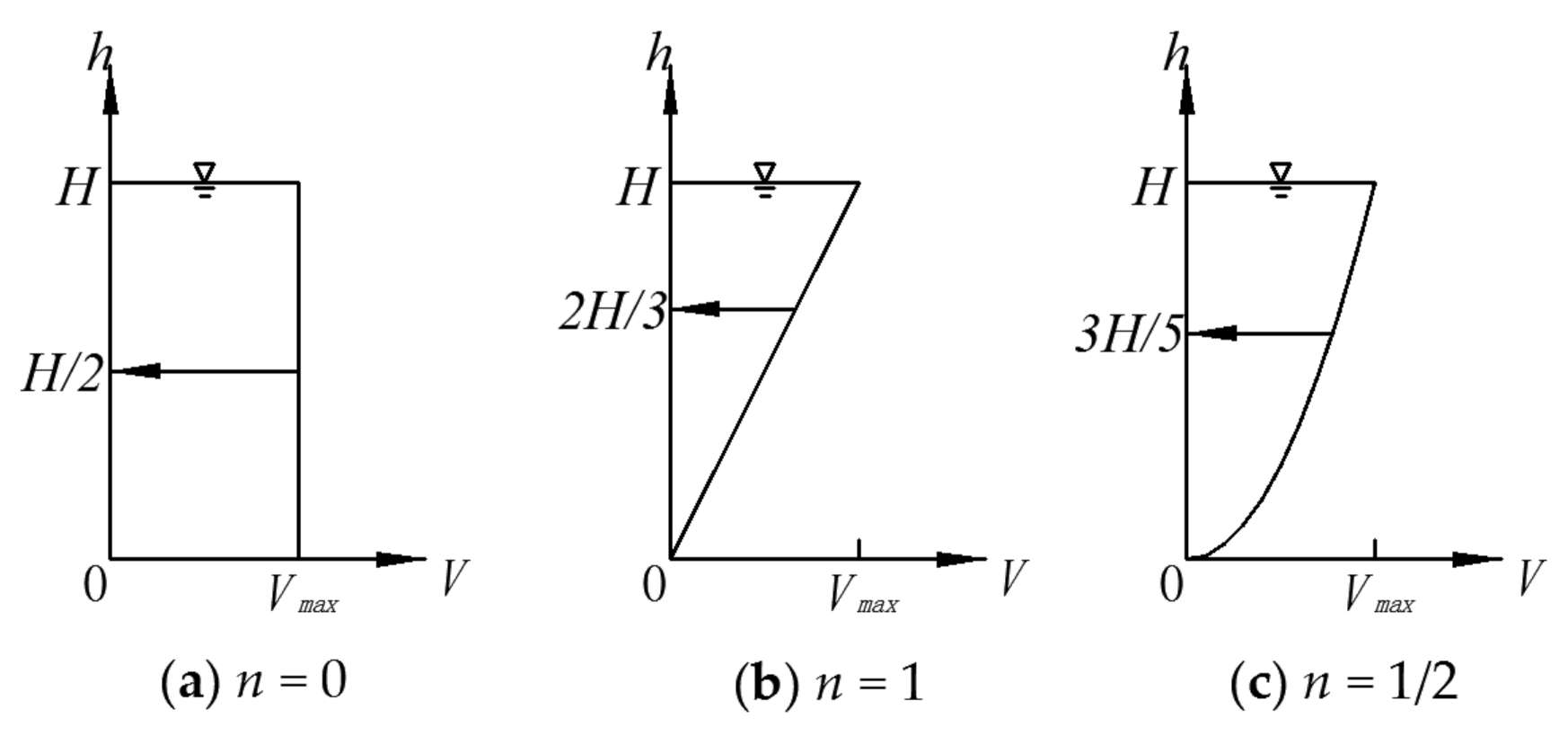
2.2. Rule of the Flow Velocity Distribution of Flocking Drainage Pipe

It is generally believed that the flow velocity presents a parabolic distribution on the vertical surface, and its curve equation is as follows [26]:
V = V m a x ( h / H ) n ,
where
  • V—flow velocity at any depth of vertical surface;
  • Vmax—flow velocity of water surface;
  • H—water depth;
  • h—water depth at any point;
  • n—constant, which was determined by the nature of water flow and the interior wall of the drainage pipe.
Figure 5 shows the flow velocity distribution curve and the joint force focus position of flowing water pressure at different n values (shown by the arrow).

3. Results and Discussion

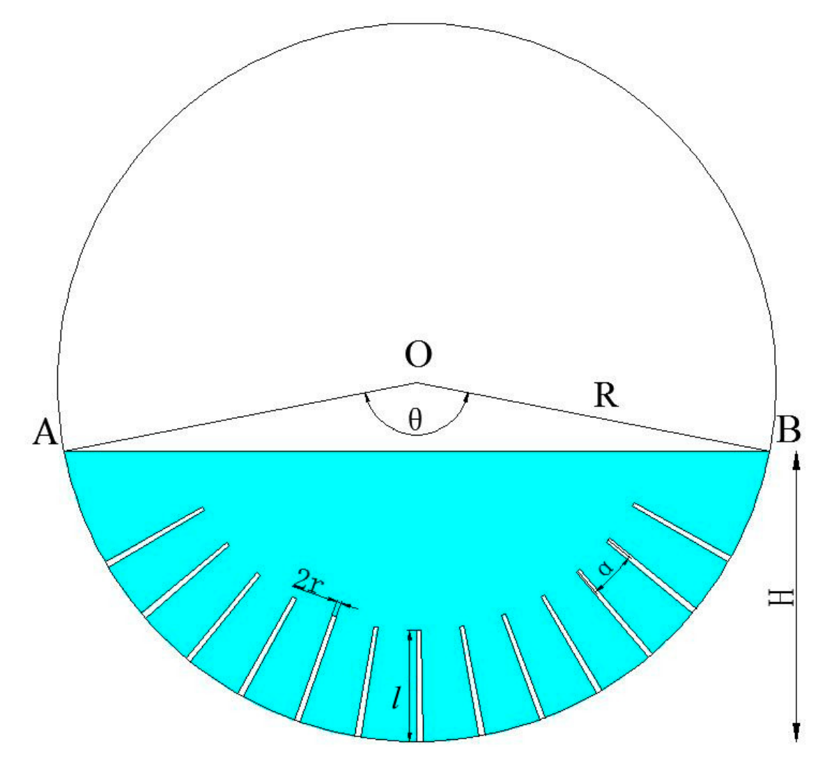
3.1. Analysis of the Flow Velocity of Flocking Drainage Pipes

Assuming mountain size A, tunnel size B and drainage pipe size C, then C < B < A and C << A. The groundwater level in the mountain is stable in most cases, and the water flow in the tunnel drainage pipe is very small compared with the groundwater in the entire mountain. According to the definition of the flow field, the groundwater flow field in the tunnel drainage pipe can be regarded as a constant flow. The existence of fluff changes the local water crossing section dimension of the flocking drainage pipe, so the groundwater flow field in the tunnel drainage pipe is non-uniform flow. In conclusion, the groundwater flow field in the tunnel drainage pipe is a constant and non-uniform flow.
For flocking drainage pipes, the average flow velocity of the section of the non-flocked part can be calculated according to Formula (2). The existence of fluff changes the local water crossing section dimension of flocking drainage pipe, so the equation for its average flow speed needed to be deduced. The average flow velocity of a flocking drainage pipe section was deduced according to the basic principle of Equation (2), and the calculation diagram is shown in Figure 6.
Area of △OAB:
A 1 = R 2 ( R H ) 2 ( R H )
Area of the fluff of the water crossing section:
A 2 = 2 r l N ,
N = θ α 1
Area of arc corresponding to θ:
A = π R 2 θ 360
Water crossing area of the flocking drainage pipe section:
A 3 = A A 1 A 2
The following equation was derived from the geometric relationship in the calculation diagram:
θ = 2 arccos ( R H R )
Equations (3)–(6) were substituted into Equation (8) to obtain:
A 3 = π R 2 180 arccos ( R H R ) R 2 ( R H ) 2 ( R H ) 2 α arccos ( R H R ) 1 2 r l
Then, Equation (10) was substituted into Equation (2), and the average flow velocity of the flocking drainage pipe section was obtained:
v = Q π R 2 180 arccos ( R H R ) R 2 ( R H ) 2 ( R H ) 2 α arccos ( R H R ) 1 2 r l ,
where
  • v—average flow velocity of flocking drainage pipe section (mm/s);
  • Q—groundwater flow in flocking drainage pipe (mL/s);
  • R—radius of flocking drainage pipe (mm);
  • H—cross-section height of groundwater in flocked drainage pipe (mm);
  • α—flocking circular spacing of flocked drainage pipe (°);
  • r—radius of fluff of flocking drainage pipe (mm);
  • l—length of fluff of flocking drainage pipe (mm); N—amount of fluff of flocking drainage pipe section.
It was assumed that the crystal fluff under water was covered by crystals during the movement of groundwater, and the thickness of crystal was r′. Therefore, we only needed to replace the r in the above Equation (11) with (r + r′), and simplify the constant term in the equation according to the mathematical modeling theory to obtain:
v = Q A 3 = Q C 1 C 2 ( r + r )
As can be seen from the above Equation (12), when the groundwater flow was constant, the greater the r′, the smaller the area of the water crossing section, and the greater the v. It was consistent with the distribution law of a 2D flow field of flocking drainage pipes by Liu et al. [24]. Through a simple mathematical transformation of Equation (12), the equation between the thickness of crystal and the flow velocity of the flocking drainage pipe section was obtained.
r = ( C 1 Q / v ) C 2 r

3.2. Analysis of the Fluff Stress of Flocking Drainage Pipe

Referring to the General Specifications for Design of Highway Bridges and Culverts issued by the Ministry of Transport of the People′s Republic of China in 2015 [27], the equation of the flowing water pressure in the flocking drainage pipe was:
F w = K A γ v 2 2 g ,
where
  • FW—standard value of flowing water pressure (kN);
  • γ—unit weight of groundwater (kN/m3);
  • v—average flow velocity of flocking drainage pipe section (m/s);
  • water resistance area by fluff (m2),
  • A = 2rl, g—acceleration of gravity, g = 9.81 m/s2;
  • K—coefficient of fluff shape, which was 0.8 for round fluff, 1.3 for rectangular fluff.
Equation (12) was substituted into Equation (14) to obtain the equation of flowing water pressure at the fluff in the flocking drainage pipe:
F w = K A γ Q 2 2 g ( C 1 C 2 ( r + r ) ) 2
It can be seen from the above formula that the amount of crystal on the fluff of the flocking drainage pipe is inversely proportional to the flowing water pressure of the fluff. When the crystals increase, the flowing water pressure on the fluff becomes greater; when the crystals decrease, the flowing water pressure on the fluff decreases.

3.3. Analysis of the Interaction between the Fluff, the Crystal and the Groundwater

During the movement of groundwater in the flocking drainage pipe, the easily crystallized anions and cations in the water form crystals, which gradually adhere to the pipe wall and the fluff. When the water pressure is greater than the adhesion force between the crystals and the fluff, the crystals are shed from the fluff. When the water pressure is greater than the adhesion force between the crystals and less than the adhesion between the crystals and the fluff, some of the crystals fall off.
The adhesion force between the crystal and the fluff:
F 1 = 2 π r l τ 1
The adhesion force between the crystals:
F 2 = 2 π ( r + r ) l τ 2 ,
where
  • τ1—adhesion force between the crystal and the fluff (kN/m2);
  • τ2—adhesion force between the crystals (kN/m2);
  • r′—fixed thickness of crystal on the fluff (m).
(1)
When the flowing water pressure was greater than the adhesion force between the crystals and the fluff, namely:
K A γ v 2 2 g > 2 π r l τ 1 ,
and through simple transformation, we obtained:
v 2 > 4 g π r l τ 1 γ K A
That is, when the squared value of test flow velocity in the field was greater than the calculated value of the right side of Equation (19), the crystals will not adhere to the fluff, but will flow out of the pipe with groundwater or adhere to the pipe wall.
(2)
When the water pressure is greater than the adhesion force between the crystals and less than the adhesion between the crystals and the fluff, namely:
2 π ( r + r ) l τ 2 < K A γ v 2 2 g < 2 π r l τ 1
and through simple transformation, we obtained:
4 g π ( r + r ) l τ 2 γ K A < v 2 < 4 g π r l τ 1 γ K A
That is to say, when the square value of the flow velocity is between the calculated value on the left side of Equation (19) and that of the right side of Equation (21), some of the crystals will be attached to the fluff, and but the remaining crystals would fall from the fluff under the effect of groundwater. By substituting the calculation results of Equation (13) into Equations (19) and (21), we determined the status of crystal on a single piece of fluff in the flocking drainage pipe.

3.4. Analysis of the Changing Law of Crystals in Flocking Drainage Pipes over Time

By using Equation (21), the changing law of r′ over time is obtained.
(1) When the initial velocity v0 met v 2 4 g π ( r + r ) l τ 2 γ K A , the crystals began to increase. When the r′ increased, the v gradually increased to v 2 = 4 g π ( r + r ) l τ 2 γ K A , and the amount of crystal on the fluff remained unchanged.
Assuming that the crystallization velocity of crystal on the fluff was constant, namely
d r d t = α 1
and by finding the derivative of both sides of Equation (12) to t, we obtained:
d v d t = Q ( C 1 C 2 ( r + r ) ) 2 C 2 d r d t = Q C 2 α 1 ( C 1 C 2 ( r + r ) ) 2 = C 2 α 1 v 2 Q
Through transformation, we obtained:
d v v 2 = C 2 α 1 d t Q
By finding the integral of the both sides of the above equation simultaneously, we obtained:
d v v 2 = C 2 α 1 d t Q , ( 1 v 1 v 0 ) = C 2 α 1 t Q , 1 v = C 2 α 1 t Q 1 v 0
Finally, we obtained:
v ( t ) = 1 ( 1 v 0 C 2 α 1 t Q )
By substituting Equation (13) into the above equation, we obtained the equation between the amount of crystal on the fluff and the time:
r ( t ) = ( C 1 Q v ( t ) ) C 2 r = ( C 1 Q ( 1 v 0 C 2 α 1 t Q ) ) C 2 r
To solve the tf in the steady state, make v 2 = 4 g π   ( r + r ) l τ 2 γ K A .
Then, v = 4 g π ( r + r ) l τ 2 γ K A = 1 ( 1 v 0 C 2 α 1 t Q ) .
We obtained t f = Q C 2 α 1 1 v 0 γ K A 4 g π ( r + r ) l τ 2 .
In summary:
When t < tf, r ( t ) = ( C 1 Q ( 1 v 0 C 2 α 1 t Q ) ) C 2 r .
When ttf, r ( t ) = ( C 1 Q ( 1 v 0 C 2 α 1 t f Q ) ) C 2 r .
(2) When the initial velocity v0 met 4 g π   ( r + r ) l τ 2 γ K A < v 2 < 4 g π r l τ 1 γ K A , some of the crystals fell from the fluff under the effect of groundwater. When the r′ decreased, the v gradually decreased to v 2 = 4 g π ( r + r ) l τ 2 γ K A , and the amount of crystal on the fluff remained unchanged.
Assuming that the falling off velocity of crystals on the fluff was constant, namely
d r d t = α 2
and by finding the derivative of both sides of Equation (12), we obtained:
d v d t = Q ( C 1 C 2 ( r + r ) ) 2 C 2 d r d t = Q C 2 α 2 ( C 1 C 2 ( r + r ) ) 2 = C 2 α 2 v 2 Q
Through transformation, we obtained:
d v v 2 = C 2 α 2 d t Q
By finding the integral of both sides of the above equation simultaneously, we obtained:
d v v 2 = C 2 α 2 d t Q , ( 1 v 1 v 0 ) = C 2 α 2 t Q , 1 v = C 2 α 2 t Q + 1 v 0
Finally, we obtained:
r ( t ) = ( C 1 Q v ( t ) ) C 2 r = ( C 1 Q ( 1 v 0 C 2 α 1 t Q ) ) C 2 r
By substituting Equation (13) into the above equation, we obtained the equation between the number of crystals on the fluff and the time:
r ( t ) = ( C 1 Q v ( t ) ) C 2 r = ( C 1 Q ( 1 v 0 + C 2 α 2 t Q ) ) C 2 r
To solve the tf in the steady state, we make v 2 = 4 g π ( r + r ) l τ 2 γ K A .
Then, v = 4 g π ( r + r ) l τ 2 γ K A = 1 ( 1 v 0 + C 2 α 2 t Q ) .
We can obtain t f = Q C 2 α 2 1 v 0 + γ K A 4 g π ( r + r ) l τ 2 .
In summary:
When t < tf, r ( t ) = ( C 1 Q ( 1 v 0 + C 2 α 2 t Q ) ) C 2 r .
When ttf, r ( t ) = ( C 1 Q ( 1 v 0 + C 2 α 2 t f Q ) ) C 2 r .
(3) When the initial velocity v0 met v 2 4 g π r l τ 1 γ K A , all crystals fell from the fluff. When t > 0,
r ( t ) = 0
That is, no crystal would attach to the fluff.

4. Conclusions

Through theoretical analysis and derivation, the conditions and operation time of crystal attachment and falling off in the flocking drainage pipe were obtained. The main conclusions were as follows:
(1)
When the groundwater velocity v0 in the pipe met v2 ≤ 4gπ(r + r′)lτ2/γKA, crystals were attached to the fluff. When the running time of groundwater in the drainage pipe was t > (Q/C2α1)((1/v0) − (γKA/(4gπ(r + r′)τ2))1/2), the crystals attached to the fluff, maintain dynamic balance.
(2)
When the groundwater velocity v0 in the pipe met 4gπ(r + r′)lτ2/γKA < v2 < 4gπrlτ1/γKA, crystals were still attached to the fluff. When the running time of groundwater in the drainage pipe was t > (Q/C2α2)((−1/v0) + (γKA/(4(r + r′)τ2))1/2), the crystals attached to the fluff, maintaining dynamic balance.
(3)
When the groundwater velocity v0 in the pipe met v2 ≥ 4gπrlτ1/γKA, crystals did not adhere to the fluff.
(4)
The adhesion between crystals and fluff and between crystals of the flocking drainage pipe needs to be determined by more in-depth experimental research, so as to improve the calculation model of the flocking anti-crystallization blocking mechanism of drainage pipes.

Author Contributions

Conceptualization, S.L., X.Z. and F.G.; Data curation, X.Z. and F.G.; Formal analysis, S.L.; Writing—original draft, S.L. and X.Z.; Writing—review & editing, S.L. All authors have read and agreed to the published version of the manuscript.

Funding

This research was funded by the National Natural Science Foundation of China (Grant No.51778095), Scientific Research Project of Emei Hanyuan Expressway Project (Grant No. LH-HT-45).

Institutional Review Board Statement

Not applicable.

Informed Consent Statement

Not applicable.

Data Availability Statement

The study did not report any data.

Acknowledgments

This research was financially supported by the National Natural Science Foundation of China (Grant No. 51778095) and the Scientific Research Project of the Emei Hanyuan Expressway Project (Grant No. LH-HT-45).

Conflicts of Interest

The authors declare no conflict of interest.

References

  1. Ministry of Transport of the People’s Republic of China. Statistical Bulletin on the Development of Transportation Industry in 2020 [EB/OL]. Available online: https://xxgk.mot.gov.cn/2020/jigou/zhghs/202105/t20210517_3593412.html (accessed on 19 May 2021).
  2. Duau, H.; Chen, F.; Yao, C.; Wang, B.; Shu, W. The phenomenon of crystal pipe blocking in karst tunnel and its induced risk. China Civ. Eng. J. 2020, 53, 332–335. [Google Scholar]
  3. Zhao, P.; Guo, X.; Ma, W. Research and application of dredge equipment for drainage pipeline in railway tunnel. Railw. Eng. 2018, 58, 30–32+66. [Google Scholar]
  4. Zhang, X.; Zhou, Y.; Zhang, B.; Zhou, Y.; Liu, S.; Li, Y. Investigation and analysis on crystallization of tunnel drainage pipes in chongqing. Adv. Mater. Sci. Eng. 2018, 2018, 1–6. [Google Scholar] [CrossRef] [Green Version]
  5. Guo, X. Crystallization mechanism and countermeasures of drainage system for railway tunnel. China Railw. Sci. 2020, 41, 71–77. [Google Scholar]
  6. Lei, L.; Hua, Y.; Li, G.; Qi, J.; Li, D. Analysis and treatment of blind pipe blockage in humaling tunnel on lanzhou-chongqing railway. Mod. Tunn. Technol. 2020, 57, 149–153. [Google Scholar]
  7. Wu, Y.; Li, G.; Jia, Q.; Qi, H.; Li, D. Study on characteristics and sources of crystal components of leakage water in the loess tunnel. Mod. Tunn. Technol. 2020, 57, 154–159. [Google Scholar]
  8. Ye, F.; Tian, C.; He, B.; Zhao, M.; Wang, J.; Han, X.; Song, G. Experimental study on scaling and cloggingin drainage system of tunnels under construction. China J. Highw. Transp. 2021, 34, 159–170. [Google Scholar]
  9. Jiang, Y.; Du, K.; Tao, L.; Zhao Jumei Xiao, H. Investigation and discussion on blocking mechanism of drainage system in karst tunnels. Railw. Stand. Des. 2019, 63, 131–135. [Google Scholar]
  10. Tian, C.; Ye, F.; Song, G.; Wang, Q.; Zhao, M.; He, B.; Wang, J.; Han, X. On mechanism of crystal blockage of tunnel drainage system and preventive countermeasures. Mod. Tunn. Technol. 2020, 57, 77–83. [Google Scholar]
  11. Zhou, W.; Wang, Y.; Li, Y.; Wang, L.; Jia, X. Research on the influence factors of crystallization and sedimentation of tunnel drainage pipeline in karst area. Highway 2021, 66, 347–352. [Google Scholar]
  12. Xiang, K.; Zhou, J.; Zhang, X.; Huang, C.; Song, L.; Liu, S. Experimental Study on Crystallization Rule of Tunnel Drainpipe in Alkaline Environment. Tunn. Constr. 2019, 39, 207–212. [Google Scholar]
  13. Zhou, Y.; Zhang, X.; Wei, L.; Liu, S.; Zhang, B.; Zhou, C. Experimental Study on Prevention of Calcium Carbonate Crystallizing in Drainage Pipe of Tunnel Engineering. Adv. Civ. Eng. 2018, 2018, 1–11. [Google Scholar] [CrossRef] [Green Version]
  14. Jiang, Y.; Du, K.; Liao, J.; Chen, X.; Xiao, H. Experimental research on maintainability of drainage facilities in lining construction joints of karst tunnel. Railw. Stand. Des. 2019, 63, 91–96. [Google Scholar]
  15. Ye, F.; Tian, C.; Zhao Meng He, B.; Wang, J.; Han, X. The disease of scaling and cloging in the drainage pipes of a tunnel under construction in Yunnan. China Civ. Eng. J. 2020, 53, 336–341. [Google Scholar]
  16. Su, Y.; Yang, H.; Shi, W.; Guo, H.; Zhao, Y.; Wang, D. Crystallization and morphological control of calcium carbonate by functionalized triblock copolymers. Colloids Surf. A Physicochem. Eng. Asp. 2009, 355, 158–162. [Google Scholar] [CrossRef]
  17. Semra, K.; Mualla, O.; Emel, A. The effect of ultrasonication on calcium carbonate crystallization in the presence of biopolymer. J. Cryst. Growth 2014, 401, 266–270. [Google Scholar]
  18. Su, M.; Han, J.; Li, Y.; Chen, J.; Zhao, Y.; Keith, C. Ultrasonic crystallization of calcium carbonate in presence of seawater ions. Desalination 2015, 369, 85–90. [Google Scholar] [CrossRef]
  19. Rayane, M.; Samira, G.; Mohamed, T. Calcium carbonate inhibition by green inhibitors: Thiamine and pyridoxine. Desalination 2017, 404, 147–154. [Google Scholar]
  20. Hong, Y.; Qian, X.; Li, J.; Yang, H.; Zhang, P. On scavenging performances of cleaning solvents for the clogging in the drainage system of karst tunnels. Mod. Tunn. Technol. 2020, 57, 160–170. [Google Scholar]
  21. Liu, S.; Zhang, X.; Lü, H.; Liu, Q.; Wang, B. The effect of flocking pvc pipe on the prevention and crystallization of tunnel drains. Sci. Technol. Eng. 2018, 18, 313–319. [Google Scholar]
  22. Liu, S.; Zhang, X.; Lü, H.; Liu, Q.; Wang, B. The effect of anti-crystallization of tunnel plumage drain pipe under different water filling state. Sci. Technol. Eng. 2018, 18, 156–163. [Google Scholar]
  23. Liu, S.; Gao, F.; Zhou, Y.; Liu, Q.; Lü, H.; Wang, B.; Xiang, K.; Xiao, D. Effect of fuzz length on the prevention of crystallization of tunnel flocking drainpipes. Sci. Technol. Eng. 2019, 19, 234–239. [Google Scholar]
  24. Liu, S.; Gao, F.; Zhang, X.; Han, F.; Zhou, Y.; Xiang, K.; Xiao, D. Experimental study on anti-crystallization law of tunnel transverse flocking drainpipe at different velocities. Asia-Pac. J. Chem. Eng. 2020, 15, 1–9. [Google Scholar] [CrossRef]
  25. Liu, S.; Zhang, X.; Gao, F.; Wei, L.; Liu, Q.; Lü, H.; Wang, B. Two-dimensional flow field distribution characteristics of flocking drainage pipes in tunnel. Open Phys. 2020, 18, 139–148. [Google Scholar] [CrossRef]
  26. Zhou, Y. Calculation of bridge water pressure. East China Highw. 1992, 5, 24–25. [Google Scholar]
  27. JTG D60-2015 General Specifications for Design of Highway Bridges and Culverts; People’s Communications Publishing House Co., Ltd.: Beijing, China, 1 December 2015. Available online: https://xxgk.mot.gov.cn/2020/jigou/glj/202006/t20200623_3312312.html (accessed on 10 October 2015).
Figure 1. Water receiver at lining leakage.
Coatings 11 00961 g001
Figure 2. Cracking of the tunnel lining.
Coatings 11 00961 g002
Figure 3. Tunnel drainage pipe blockage by crystals.
Coatings 11 00961 g003
Figure 4. The average flow velocity of a flocking drainage pipe section.
Coatings 11 00961 g004
Figure 5. The flow velocity distribution curve and the joint force focus position of flowing water pressure: (a) n = 0; (b) n = 1; (c) n = 1/2. [26].
Coatings 11 00961 g005
Figure 6. The average flow velocity of the flocking drainage pipe section.
Coatings 11 00961 g006
Publisher’s Note: MDPI stays neutral with regard to jurisdictional claims in published maps and institutional affiliations.

