Article

Comparison of the Growth and Thermal Properties of Nonwoven Polymers after Atomic Layer Deposition and Vapor Phase Infiltration

1
VTT Technical Research Centre of Finland, P.O. Box 1000, FIN-02044 Espoo, Finland
2
Department of Chemistry, University of Helsinki, P.O. Box 55, FI-00014 Helsinki, Finland
*
Author to whom correspondence should be addressed.
Coatings 2021, 11(9), 1028; https://doi.org/10.3390/coatings11091028
Submission received: 27 July 2021 / Revised: 13 August 2021 / Accepted: 19 August 2021 / Published: 26 August 2021
(This article belongs to the Section Surface Characterization, Deposition and Modification)

Abstract

:
The growth mechanism of Atomic Layer Deposition (ALD) on polymeric surfaces differs from growth on inorganic solid substrates, such as silicon wafer or glass. In this paper, we report the growth experiments of Al2O3 and ZnO on nonwoven poly-L-lactic acid (PLLA), polyethersulphone (PES) and cellulose acetate (CA) fibres. Material growth in both ALD and infiltration mode was studied. The structures were examined with a scanning electron microscope (SEM), scanning transmission electron microscope (STEM), attenuated total reflectance-fourier-transform infrared spectroscopy (ATR-FTIR) and 27Al nuclear magnetic resonance (NMR). Furthermore, thermogravimetric analysis (TGA) and differential scanning calorimetry (DSC) analysis were used to explore the effect of ALD deposition on the thermal properties of the CA polymer. According to the SEM, STEM and ATR-FTIR analysis, the growth of Al2O3 was more uniform than ZnO on each of the polymers studied. In addition, according to ATR-FTIR spectroscopy, the infiltration resulted in interactions between the polymers and the ALD precursors. Thermal analysis (TGA/DSC) revealed a slower depolymerization process and better thermal resistance upon heating both in ALD-coated and infiltrated fibres, more pronounced on the latter type of structures, as seen from smaller endothermic peaks on TA.

1. Introduction

Atomic Layer Deposition (ALD) is a surface controlled layer-by-layer process based on self-limiting gas-solid reactions between volatile precursors and reactive sites at the substrate, forming pinhole-free, uniform and conformal thin films [1,2,3]. Currently, commercial ALD applications range from microelectronics, photovoltaics and displays to optics, protective coatings and biomedical applications [4,5,6]. Most of these innovations are based on ceramic materials when metal oxide coatings are deposited on inorganic surfaces. However, an interest towards ALD on natural and synthetic polymeric surfaces is increasing constantly. Deposition of Al2O3 onto polyethylene and SiLKTM were accomplished at the beginning of the 2000’s, and ALD growth on polymeric surfaces in the form of sheets, particles, membranes and biopolymers have been studied since [7,8,9,10,11,12,13,14,15,16,17,18]. The work on ALD coatings on polymeric surfaces opens various possibilities for a wider range of applications including materials for packaging, printed flexible electronics, membranes for environmental applications, biomedicine, catalysis, solar cells and other energy applications.
ALD on polymeric substrates is a thermally restricted process due to the low glass transition and melting temperatures of the organic materials. The thermal budget can be lowered with plasma-enhanced ALD, but at the same time it can also deteriorate the polymer surface [19]. ALD growth on polymers is often non-linear, especially at the beginning of the deposition process and at low temperatures, since during the nucleation period precursors adsorb onto the surface and possibly into the sub-surface regions [10,11,18,20,21,22,23]. During the initial growth, metal oxides can nucleate and form clusters [24,25]. According to several studies, the structure of the coatings depends strongly on the polymer composition [3,11,26,27,28]. The opinions concerning the role of different polar groups as adsorption sites are diverse, but it is likely that these form the basis for nucleation and initial growth as demonstrated with self-assembled monolayers [29]. Furthermore, surface roughness, nucleation effects and unreactive adsorption sites explain abrupt changes in the surface energy of the base material during the first deposition cycles [30,31]. Prolonged exposure or surface pre-treatments may also cause detrimental changes in the substrate affecting film growth, uniformity and film properties, such as barrier properties [32,33].
The most studied reaction suitable for thermal ALD is based on TMA (trimethylaluminum) and water. This process is producible even at 33 °C, although the physisorption of the gaseous precursors results in relatively long purging times [8]. Nucleation and growth of Al2O3 on various polymers have been studied widely [8,10,11,12,30,34,35]. Wilson et al. studied the growth of Al2O3 on polystyrene (PS), polypropylene (PP), poly(methyl methacrylate) (PMMA), polyethylene (PE), and poly(vinyl chloride) (PVC), and concluded that the nucleation was dependent mainly on TMA uptake, and did not require specific chemical groups on the polymer [10]. Respectively, the growth of a ZnO ALD coating on PP, PMMA, PC, PET and P3HT have been studied by several groups [21,36,37,38,39,40,41,42,43,44].
In addition to ALD, the mechanical properties of biopolymers have been enhanced by precursor infiltration [18,22]. It is based on ALD where prolonged precursor diffusion into the polymer substrate structure and interaction with the functional groups at the molecular level alters the polymer properties [10,22,28,45,46]. Azpitarte et al. reported recently about the improved stability and mechanical properties of the polyaramide (Kevlar). With infiltrated and hybridized ZnO, the degradation temperature increased, and thermal and ultraviolet sensitivity of Kevlar were suppressed [47]. In addition, McClure et al. noticed that the Al2O3 ALD treatment and precursor infusion increased the Young’s modulus and mechanical strength of nylon 6, polypropylene, and pellethane fibres [48]. Furthermore, infiltration has been used for improving the conductivity of polymers like polyaniline and polythiophene, such as poly(3-hexylthiophene-2,5-diyl (P3HT) [49,50].
Previously, Al2O3 and ZnO ALD coatings on PLLA and PES polymers have been studied by several research groups [40,51,52,53,54]. Vähä-Nissi and his colleagues observed the enhancement of barrier properties of PLLA with Al2O3 and ZnO coatings. Choi et al. reported changes in crystallinity, roughness and density, depending on the structure of the ZnO/Al2O3 laminate grown at 60 °C [52]. The polymeric material in these studies was either a commercial film or fabrics. In the present paper, we concentrate on the growth of thermally ALD-grown Al2O3 and ZnO on three different polymers (PLLA, PES, CA) in fibrous form. Fibrous substrates for deposition trials were made by electrospinning due to relatively small diameters and the large specific surface area of such materials; there is a possibility to cover samples from all sides. Furthermore, the thermal properties of the prepared materials are studied.

2. Materials and Methods

2.1. Materials

The polymers were cellulose acetate (CA) from Acros Organics (Mw 100,000) (Waltham, MA, USA), polyethersulphone (PES) from Goodfellow (Mw 58,000) (Goodfellow Cambridge Limited, Huntingdon, England) and poly-L-lactide (PLLA) from Purasorb (PL24, Mw 339,000, Tm 173–178 °C). Solvents used in electrospinning were acetone (Ac), chloroform (CHCl3), N-methyl pyrrolidone (NMP), N,N-dimethyl acetamide (DMAc), and N,N-dimethyl formamide (DMF) (Sigma-Aldrich, Helsinki, Finland). The reactants used in the ALD processes were trimethylaluminum (TMA) from SAFC (99.999%) (St. Louis, MO, USA) and from Strem Chemicals (Newburyport, MA, USA), diethylzinc (DEZ) from SAFC (> 52%) (St. Louis, MO, USA) and from Strem Chemicals and deionized water. Ozone was generated by IN USA, Inc. (Norwood, MA, USA), ozone generator from 99.99% O2 (AGA, Espoo, Finland).

2.2. Methods

Fibrous substrates from CA, PLLA and PES were prepared by electrospinning. The spinning process and parameters are presented in the Supplementary information, and the preparations of the electrospinning solutions and the electrospinnability trials are described by Heikkilä et al. [55]. Electrospun materials were nonwoven sheets thick enough to handle as self-sustaining sheets. Electrospinning materials obtained have loose structures beneficial for coating and infiltration processes (see Figure 1). The average fibre diameters of these fibres were (430 ± 350) nm, (540 ± 270) nm and (400 ± 270) nm, respectively.
PLLA reference substrates were prepared by encapsulation by solvent evaporation (polymer powder) in the following manner. PLLA powder was prepared from polymer pellets (Purasorb) with the encapsulation by solvent evaporation [56,57]. In the process, the 4% PVA and PLLA polymers were mixed in methylene chloride (10 wt.%) solutions in a 9:1 ratio. The solution was stirred overnight at 500 rpm, after which the methylene chloride was evaporated. The PLLA precipitate was centrifuged and the PVA removed by washing with hot water. The average size of the yielded PLLA particles was 100 μm (field emission scanning electron microscope, FE-SEM ).
ALD coatings were performed in a Picosun R-200 ALD (Espoo, Finland) reactor in single wafer mode. Nitrogen (>99.999%) was used as a carrier gas. Al2O3 was produced using TMA either with water or ozone as an oxygen source. The TMA precursor was stored in a metallic container and evaporated at room temperature. The precursor dose/purge times (s) were 0.2 s (TMA)/15 s/0.2 s (H2O)/15 s (for TMA + H2O) and 0.2 s (TMA)/15 s/2.5 s (O3)/15 s (for TMA + O3). For ZnO using DEZ + H2O, the dose/purge times (s) were 0.3 s (DEZ) / 10 s/0.2 s (H2O)/10 s (DEZ + H2O). The cycle amounts varied between the processes, and target thicknesses were 2, 5 and 30 nm.
Infiltration of the substrates was performed in a commercial ALD reactor (Savannah S100, Cambridge NanoTech Inc, Cambridge, MA, USA). The infiltration was carried out at 100 °C under a constant nitrogen gas flow of 20 sccm. DEZ and TMA were used as the metal source and demineralized water as the oxygen source. The substrates were exposed to the precursors for defined periods of time before purging, thereby allowing diffusion of the precursors into the polymer. An infiltration cycle consisted of Pulse (DEZ, 0.08 s)/Exposure (30 s)/Purge (N2, 30 s)/Pulse (H2O, 0.08 s)/Exposure (30 s)/Purge (N2, 30 s).

2.3. Characterization

Scanning electron microscope (SEM) imaging was carried out with a ZEISS Merlin (Carl Zeiss GmbH, Jena, Germany), FE-SEM with a secondary electron detector, an acceleration voltage of 2 kV and a probe current of 60 pA and gold sputtered samples. The morphologies and microstructures of the synthesized samples were characterized by scanning transmission electron microscopy (STEM) FEI Titan G2 60–300 (Hillsboro, OH, USA), operating at 300 keV, in scanning mode.
Fourier-transform infrared spectroscopy (FTIR). The chemical functionalities in the polymer surfaces (granules, powder, fibres), Si reference surface, as well as ALD coated and infiltrated surfaces were identified with a Fourier-transform infrared (Nicolet iS50 FTIR (Thermo Fischer Scientific, Waltham, MA, USA) spectrometer using a single reflection 60° germanium attenuated total reflectance (ATR) crystal and the horizontal accessory VariGATR. ATR-FTIR spectra were collected by averaging 64 scans at a resolution of 4 cm−1 in the scan region between 4000 and 590 cm−1. The chemical functionalities after infiltration were studied by ATR-FTIR on a Perkin Elmer Frontier spectrometer with an UATR sampling stage. All spectra were measured with 20 scans between 4000 and 520 cm−1 at a 4 cm−1 resolution. Each sample was measured 5 times and the results were averaged.
Solid state nuclear magnetic resonance (NMR). Al2O3 coordination as a function of ALD cycles was evaluated by solid state 27Al NMR experiments carried out using an Agilent DD2600 (Agilent Technologies, Santa Clara, CA, USA) NMR spectrometer (magnetic flux density 14.1 T), equipped with a 3.2 mm triple resonance T3 MAS probehead, set up to a double resonance operation. All spectra were externally referenced via the 13C spectrum of adamantine by setting the low field signal to 38.48 ppm. The samples were packed into ZrO2 rotors with KEL-F endcaps, with the same rotor having been used throughout the experiments. The spinning rate was set to 20 kHz. The duration of the excitation pulse was 0.7 µs, and the repetition delay between pulses was 0.2 s, with 1,480,000 repetitive scans. A background spectrum with an empty rotor, acquired under identical experimental conditions, was subtracted from the spectra. After background subtraction, a cubic spline baseline correction was applied. All spectra were processed with MNova 13 (MestreLab) and ssNake [58].
Tensile tests were performed with a BRUKER Universal Mechanical Tester with a resolution of 50 μN and in accordance with the ASTM standard C1557-03 (2008). The sample piece (2 mm × 10 mm) was fixed in a cardboard sample holder, which had a punched hole of 6 mm diameter in the centre. After vertical alignment of the sample across the hole, the sample holder was positioned in the mechanical tester with the sample being unstrained. Finally, the sample holder was cut along the central guides and tensile force was applied until rupture of the sample, while the strain was measured simultaneously. The results are presented in the Supplementary information.
Thermogravimetric analysis/differential scanning calorimetry (TGA/DSC). Simultaneous thermal analyses were carried out for determining the thermal degradation properties of the samples by using a Netzsch STA 449 F1 thermal analyser (Netzsch, Selb, Germany). The resulting curves were analysed with the Proteus 6.1 software. The heating rate was 10 K/min in a nitrogen environment.

3. Results and Discussion

3.1. Al2O3 and ZnO Growth on Polymers

The appearance (SEM images) of the polymeric fibres before and after the targeted 2 nm and 30 nm thick Al2O3 and ZnO coatings on CA, PLLA and PES are shown in Figure 2, Figure 3 and Figure 4, respectively. In the case of CA, the deposited Al2O3 is conformal and smoothens the surface morphology of the fibre (Figure 2). The smoothening cannot be explained with the bare Al2O3 layer, since a 2 nm thick layer of Al2O3 is not enough to smoothen such grooves (Figure 2b), thus probably some polymer swelling is occurring. However, the DEZ + H2O process resulted in grainy growth, and the gravures can be seen in both images (Figure 2d,e). Because of the uneven growth of ZnO on CA, we also applied a pre-deposition of 10 cycles of Al2O3 onto the surface, before a deposition of 30 nm of ZnO in a separate experiment. In this case, the gravures could not be detected after the deposition (Figure 2f).
The same phenomenon was also observed from PLLA and PES. The Al2O3 process seems to modify the structure of PLLA, while the ZnO process does not (Figure 3). The PES fibre surfaces (Figure 4) were already smooth prior to ALD coating, which made observation of the film growth more difficult. However, differences between the coatings can be pointed out, since there are cracks on the Al2O3 coatings, tiny in 2 nm thick coatings and wider in 30 nm thick coatings (Figure 4b,c). These cracks are probably resulting from mechanical embrittling of the material and cracking upon bending. ZnO showed uniform crack-free growth on the PES surface.
Since already 2 nm of Al2O3 resulted significant changes in CA surface morphology, additional STEM imaging was carried out. STEM images were acquired to analyse the thickness and morphology of the deposited coatings with an expected thickness of 30 nm, as measured from reference Si substrates (Figure 5). The coated CA fibres (Figure 5a) have a smooth Al2O3-coating of about 21.5 nm thickness, which appears homogeneous, although the thickness is somewhat lower as compared to the expected value. The CA fibres themselves have been decomposed due to the generated heat from the electron beam during STEM characterization. However, this does not explain the smoothening of the surface during ALD. In ZnO-coated CA fibres (Figure 5b), the coating is less homogeneous, and its thickness is only around 10.8 nm, being approximately 1/3 of the target. Upon closer looking (high magnifications not shown here), it is granular, which indicates that the deposition proceeded through nucleation spots of ZnO.
For Al2O3-coated PES (Figure 5c) the coating is a complete shell wrapping the fibre. Its thickness is close to what is expected, being about 31.3 nm. In this case, there is a gap between the fibre surface and the coating, indicating detachment of the film from the surface. This gap could be the reason for the fibres to not decompose during the characterization since it limits the thermal conduction. In contrast, for ZnO-coated PES fibres (Figure 5d), the thickness is approximately 14 nm. The coating is non-homogeneous, and it is generated after the nucleation of ZnO in spots. Like on the CA, the Al2O3 coating thickness on PES amounts to twice that of ZnO.
PLLA (Figure 5e) shows a relatively thick Al2O3 coating with a thickness of approximately 80–90 nm. Similar to the CA with the Al2O3 coating, here the polymer also evaporated upon characterization due to the heat generated by the electron beam. Bubbles are observable inside the coating after few minutes’ exposure to the electron beam. The thick Al2O3 coating is an indication of a non-ideal ALD growth, although high uniformity of the films is still indicating controlled growth, such as infiltration of the precursors into the porous fibre. On PLLA fibres, no ZnO coating was observed by STEM (Figure 5f). EDX measurements showed less than 1 at.% Zn in the samples, which indicates that no ALD deposition occurred.

3.2. Study of Film Growth and Interactions

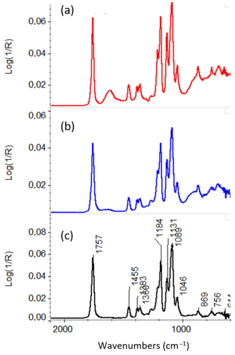
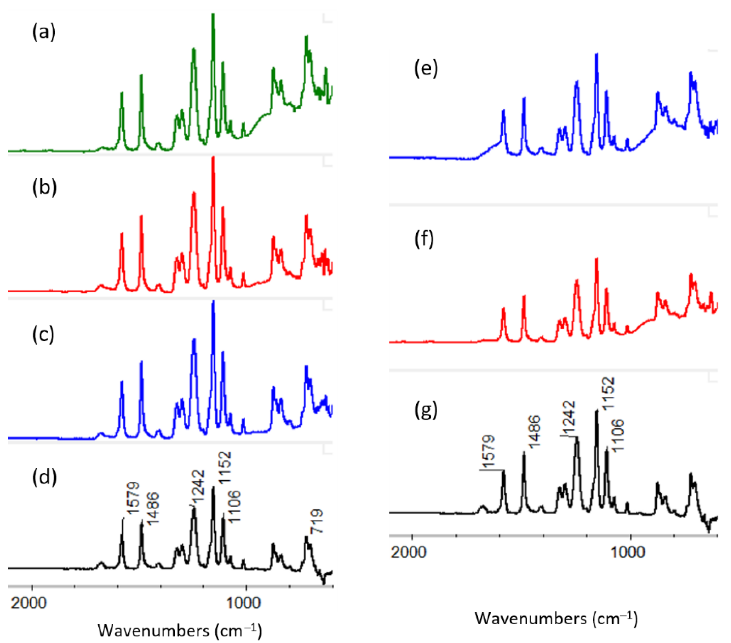
3.2.1. ATR-FTIR of ALD Deposited Materials

The samples were analysed with ATR-FTIR in order to identify the species present at the surface. The CA, coated with 30 nm Al2O3, showed the baseline shift in the region 590–900 cm−1 indicating presence of aluminium oxide (Figure 6). With TMA + O3, the formation of Al-formate can be detected with the signal at 1610 cm−1 (dotted line, in Figure 6). It is expected that the TMA + O3 process results in AlOCH3 (methoxy), Al(OCHO) (formate), Al(OCOOH) (carbonate) and AlOH (hydroxyl) species. Previously, it has been shown that the formation of the various carbon-containing species is temperature dependent and that their formation can be prevented with processing temperatures of 380 °C or more [40,59]. The CA-fibres with a 30 nm thick ZnO coating (Figure 6, right) show typical CA-bands and a baseline shift in the region 590–700 cm−1. This baseline shift and the band at the wavenumber of 643 cm−1 indicate the presence of ZnO, since ZnO stretching vibrations are typically found at around 450–681 cm−1.
In the ATR-FTIR spectra of PLLA fibres, the Al2O3 coating was detectable only after 300 ALD cycles (80–90 nm according to STEM) (Figure 7). Thinner coatings were detectable on the reference Si surface and CA fibres, indicating a different growth mechanism. The sample with the thickest Al2O3 shows a baseline shift and a broad band at 600–900 cm−1, stemming from the aluminum oxide. The PLLA appears to be unchanged, since the PLLA bands are similar in both the coated and uncoated fibre spectra (Figure 7). A comparison of the samples, processed with H2O or O3 as counter precursors, shows a similar chemistry as in the case with CA. Namely, with ozone, the formation of Al-formate is observed with the appearance of a band at 1610 cm−1, while with H2O only a small intensity peak is seen. The ATR-FTIR spectra of ZnO-coated PLLA fibres (30 nm) show the typical PLLA bands and a very weak baseline shift in the region of 640–700 cm−1 (spectrum not shown). The baseline shift indicates the presence of ZnO, but not as defined as it was the case with ZnO-coated CA fibres.
The ATR-FTIR analysis of Al2O3-coated PES (Figure 8, left) showed weak aluminum oxide signals even with the thinnest ALD layers. With 30 nm thickness, the baseline shift in the region of 628–900 cm−1 was more pronounced. The Al2O3 coatings, deposited with either H2O or O3, are similar to those on CA and PLLA, where the baseline is shifted in the area around 1600 cm−1 due to the formation of carbonaceous species with O3 as precursor (Figure 8, blue spectrum). Similar to CA and PLLA, the detection of ZnO on PES is challenging. However, the band shift at 681 cm−1 is detectable with a 30 nm thick ZnO coating, indicating the presence of ZnO on the fibre surface (spectrum not shown).

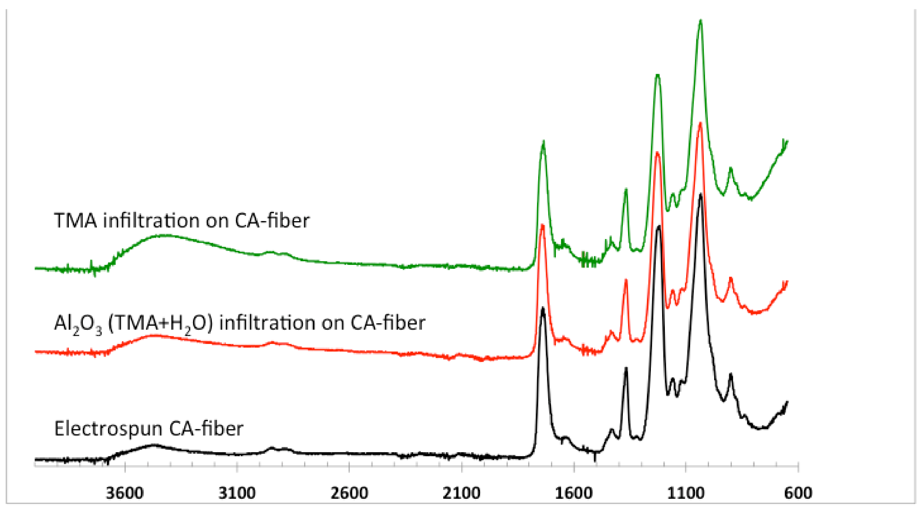
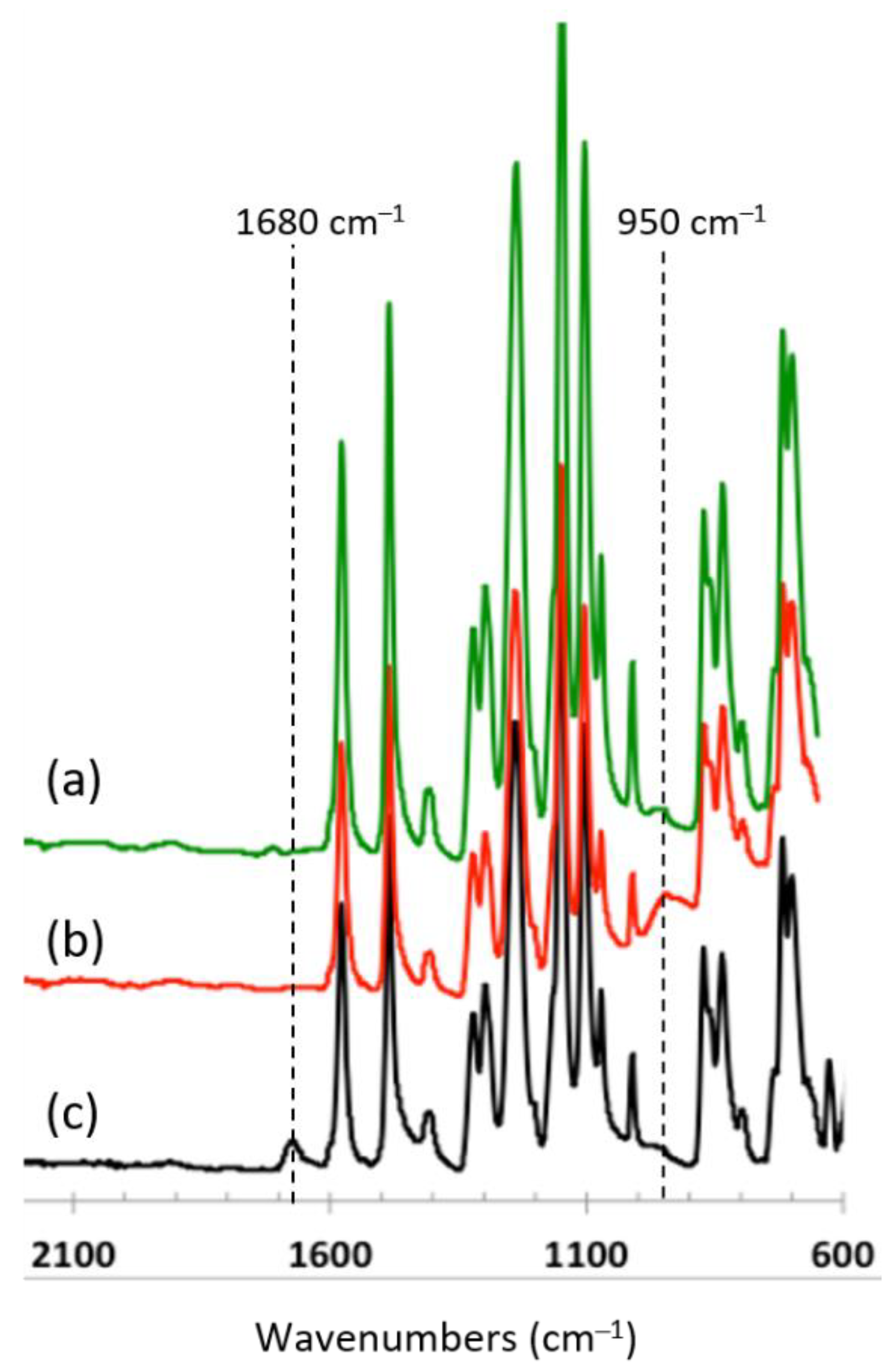
3.2.2. ATR-FTIR of Infiltrated Materials

CA and PLLA substrates infiltrated with TMA or DEZ alone, as well as treated with metal precursor and water, were measured with ATR-FTIR to evaluate possible chemical interactions between the polymer and the precursors or from the formation of the metal oxides.
A clear broadening of the O–H stretching band at 3400 cm−1 occurs after the infiltration of the CA with TMA (Figure 9). This change may indicate a distortion of the intermolecular hydrogen bonds due to the reaction of the TMA with the hydroxyl groups. However, this broadening is not observed in the Al2O3-infiltrated sample. Since the TMA-treated samples were transferred under ambient conditions to ATR-FTIR, the high amount of OH groups can occur due to the reaction with moisture at room temperature conditions. The baseline shifts in the region (600–800 cm−1), especially in the TMA infiltrated sample, due to the presence of aluminium oxide species. Therefore, it may be concluded that the infiltrated TMA reacts with the hydroxyl groups of the CA, but this interaction is weakened by the reaction of the TMA and water, and thus the formation of Al2O3. In contrast to the Al2O3-infiltrated fibres, ZnO and DEZ infiltrated CA fibres do not show any observable changes in their vibration bands (Figure S1).
The TMA and TMA + H2O infiltrated PLLA samples degraded during the treatment. The FTIR spectra (Figure 10, left) show a shift in the baseline between 900 and 600 cm−1, indicating the presence of aluminium oxide. A new broad band is observed at around 1650 cm−1, which indicates possibly some Al-formate structures and formation of C=O bonds as a consequence of the degradation of the polymeric chain. Due to the strong degradation, it was not possible to measure the TMA-infiltrated sample. After ZnO infiltration, several changes were observed in the FTIR spectra of the PLLA. The small band at 1160 cm−1 (C–O stretch in esters) vanishes, while a new band appears at 920 cm−1 (OC–OH stretch in carboxylic acids) (Figure 10, right). This indicates chain scissoring and degradation of the polyester to carboxylic acids. The same changes are observed from the DEZ-infiltrated fibres, indicating that the reaction is driven by Zn and not by hydrolysis or treatment temperature.
After TMA or DEZ infiltration into PES (Figure 11), a band at 1680 cm−1 vanishes, which may originate from residual solvent. A new broad band at 950 cm−1 appears, indicating degradation of the ester to carboxylic acid (C–O–H bending). These changes do not appear in the TMA-infiltrated sample; thus, water plays an important role here. In contrast, no obvious changes occur in the PES bands after ZnO infiltration, besides the residual solvent removal (Figure S2).
According to SEM and STEM results, in the case of all polymers, the ZnO coating was non-homogeneous and nucleation centers were observed. This is most probably the reason for weak spectral changes in the ATR-FTIR spectrum in the case of both layer deposition and infiltration. PLLA fibres degraded partially during the infiltration, and the growth was nonideal according to the STEM images. With PES fibres, the Al2O3 coating and infiltration was detectable both with STEM and ATR-FTIR techniques, but there were more variations in thicknesses and infiltration reactions compared to CA fibres. Since on average the growth of Al2O3 was most stable on CA, this material combination was selected for further studies with 27Al Solid state NMR, tensile tests (mechanical behaviour results presented in Supplementary information), and TGA/DSC for revealing the altered thermal properties.

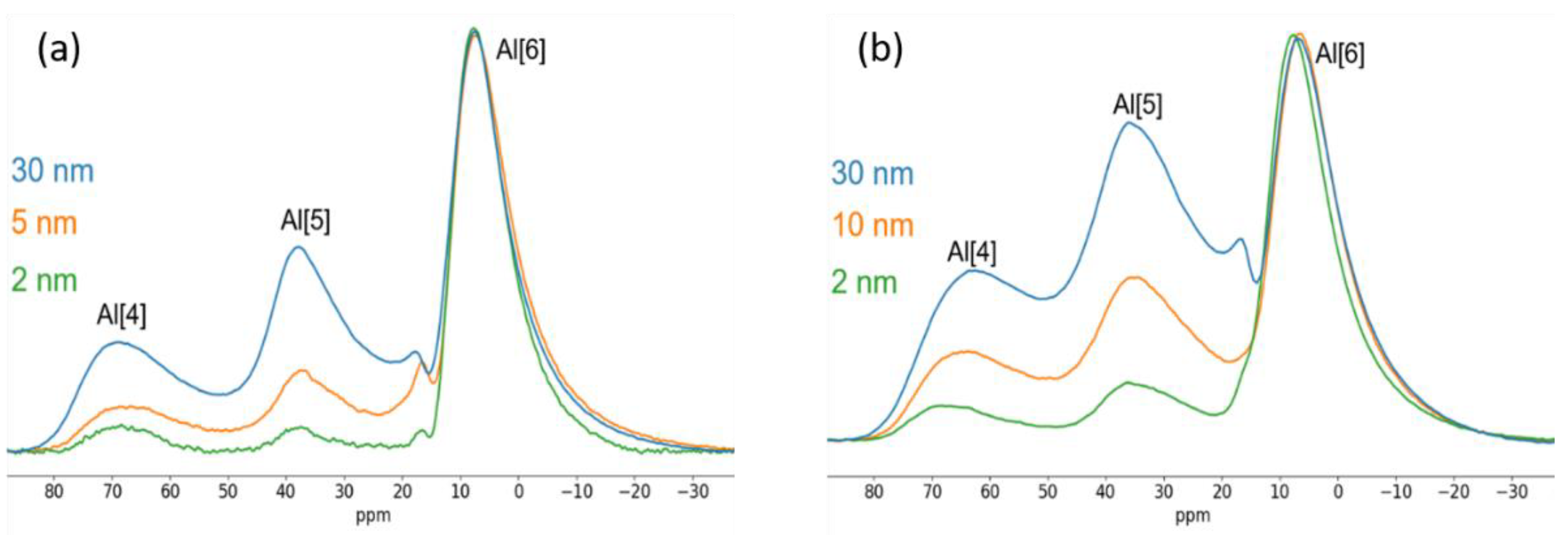
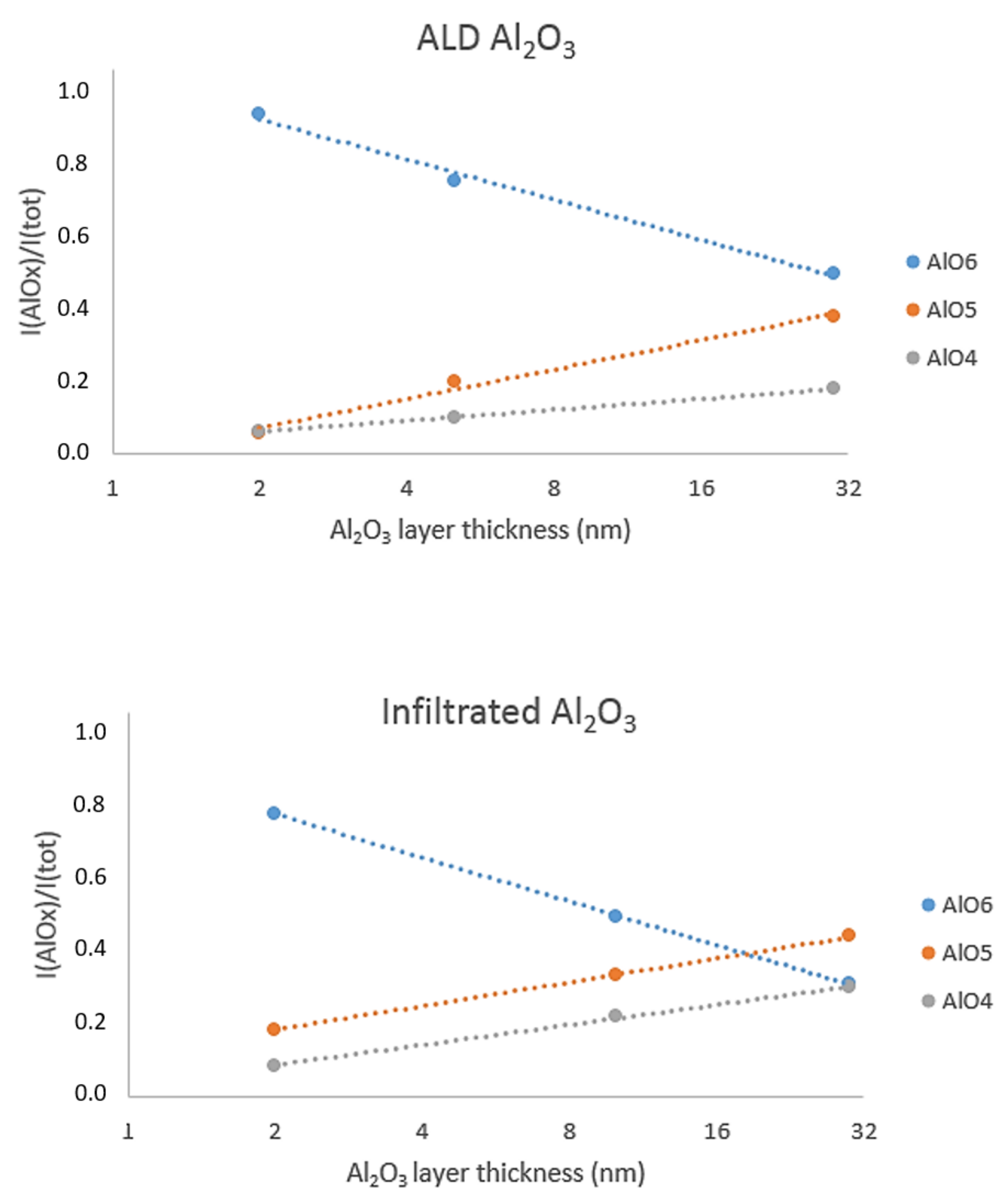
3.2.3. 27Al Solid State NMR

While in crystalline alumina polymorphs the structural units consist of AlO4 and AlO6 units [60], amorphous alumina has more structural diversity. The 4- and 6-coordinated structures may have distortions in their bond angles and lengths, and they also contain 5-coordinated aluminium species [61]. It has been shown that the deposition temperature affects the relative amounts of different coordination species in thin amorphous alumina films, and that the highest disorder corresponds to the lowest concentration of AlO6 units [62]. Particularly, the fraction of 5-coordinated Al is considered to be a measure for the extent of disorder. The 27Al solid-state MAS NMR spectra of the Al2O3-coated CA samples with different layer thicknesses are shown in (Figure 12a).
The typical signals associated with different coordination environments appear at approximately 0–20 ppm (AlO6), 20–50 ppm (AlO5), and 50–80 ppm (AlO4). The distortion in the spectra at around 17 ppm is an artefact resulting from the baseline subtraction. Initially, the main structural unit in the Al2O3 layer is AlO6, with lower amounts of AlO4 and AlO5. This resembles the results obtained by Lee and Ahn [63], who studied sputtered amorphous alumina thin films with thicknesses varying from 5 nm to 1400 nm. To understand how the polymer matrices affect the layer growth, infiltrated samples were analysed together with samples prepared using standard ALD process (Figure 12 b).
The relative amounts of the different aluminium coordination environments were obtained by fitting a Czjzek distribution into corresponding signal areas in the solid-state 27Al spectra [64]. An example of the result of such fitting is shown in Figure S3 (Supplementary information). The results for infiltrated and conventional ALD processes are shown in Figure 13. The intensities (normalized to the total intensity of the spectrum) of the various fractions with different coordination sites are depicted as a function of the layer thickness. In both infiltration and coating, the 6-coordinated Al-species is initially the dominating species (74% of the total signal area in infiltrated, 87% in conventional ALD), with its relative amount decreasing with an increased layer thickness. In the infiltrated sample the relative amount of 5-coordinated aluminium is higher (18%) than in the conventionally deposited samples (5%). When comparing the change in the coordination environments during the layer growth, it can be seen that the growth rate of AlO5 in the case of infiltrated samples is similar to that of AlO4, with the amount of AlO5 being approximately 2.4-fold between 2 nm and 30 nm samples. For the conventional ALD process the AlO5 content increases more rapidly, and there is a 6.7-fold increase in the AlO5 amount in the 30 nm thick film when compared to the 2 nm thick film.
The biggest difference in conventional ALD and infiltration is the precursor pulse times and the doses leading to different precursor diffusion depths into the polymer substrate. It is expected that during infiltration, a larger effective substrate area is being affected, whereas conventional ALD is primarily happening at the surface of the fibres. It can be speculated that the higher amount of 5-coordinate aluminium can be attributed to the interactions between the deposited layer and first deposited layers.

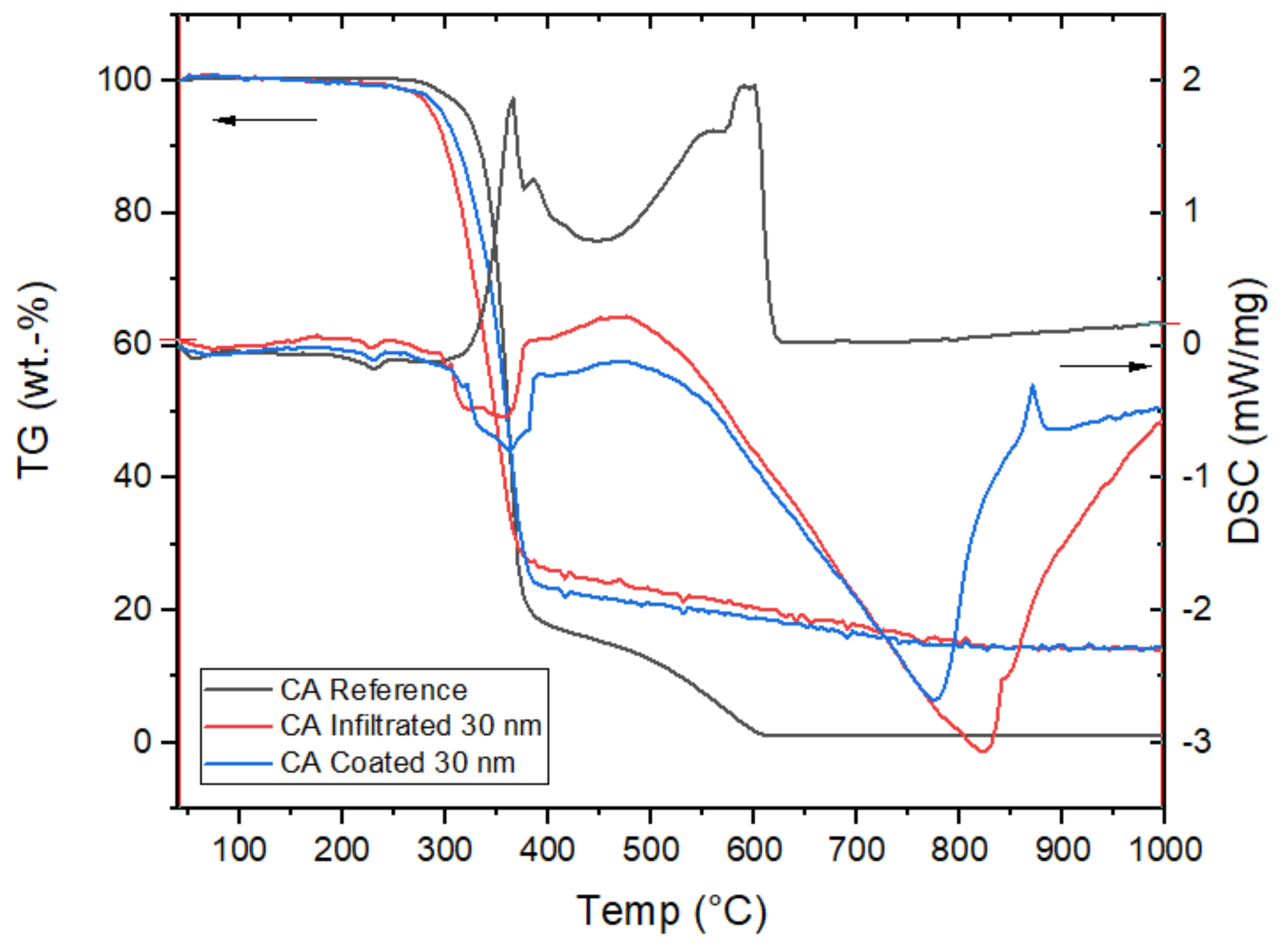
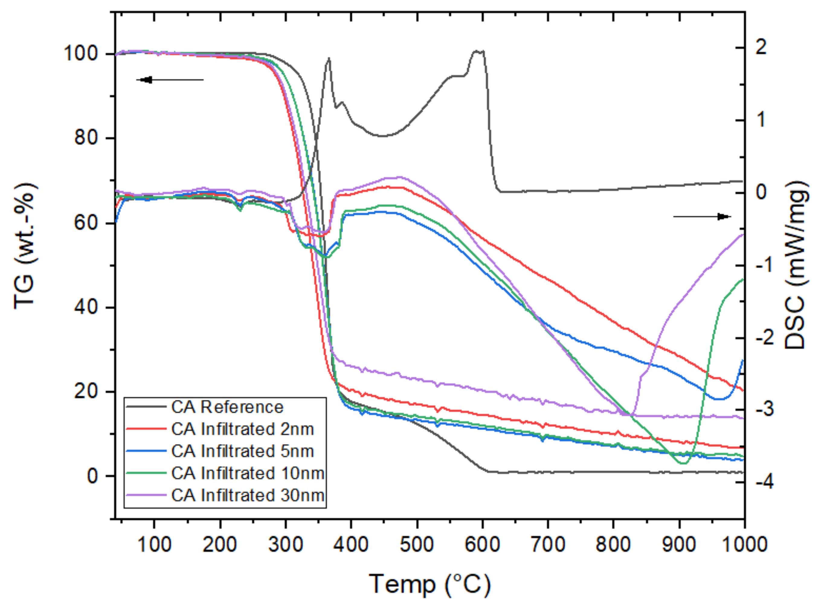
3.2.4. Thermal Behaviour

According to TGA, the thermal degradation of Al2O3-coated and -infiltrated CA takes place in the temperature range of 30–400 °C, being close to the reported values for CA bare fibres [65]. However, both infiltration and ALD coating changed the shape of the TG curve, showing an onset of material degradation earlier than that of the reference fibres. The TG curve of the reference material showed the lowest residual mass, since polymers degrade within the applied temperature range and possible residual Al2O3 in the ALD-treated samples is the final product (Figure 14). Furthermore, the deposited Al2O3 coating protects the fibres better from thermal degradation than the infiltrated Al2O3 since degradation starts earlier with the infiltrated fibre. In addition, the following degradation step, the complete depolymerization of the degradation products beyond 380 °C, proceeds much more slowly with the alumina-treated samples than with the reference sample. Furthermore, at the end of the degradation, the amount of deposited Al2O3 is around 15%, and at 400 °C the amount of the polymer is around 14%–17% in the reference and in both ALD samples, which shows a good correlation between all sample types. The DSC curves show the first endothermic peak in both the reference sample and the ALD-treated fibres at approximately 240 °C, which signifies the melting temperature. Thereafter endothermic (ALD samples) and exothermic (reference sample) phase changes can be detected in the temperature range between 300 and 400 °C. The exothermic peaks around 840 °C (infiltrated) and 870 °C (coated) samples show phase transitions, which in this case are likely related to crystallization of amorphous Al2O3 [66,67,68].
The slope of the TGA curves of infiltrated Al2O3 on CA in the temperature range of 400–1000 °C is similar in all the samples (Figure 15) The illogicality of the placing of 2 nm infiltration can be explained by the unevenness of electrospun substrate material. Since there is irregularity both in electrospun CA and the infiltrated material, it is possible that small amounts of infiltrate are mingled. The endothermic DSC peaks shift to lower temperatures while the infiltrated amount of Al2O3 increases. In the case of reference fibres, the sample is completely degraded at 615 °C. For ALD-coated samples, the shift of the endothermic peaks in DSC is similar to that with infiltrated fibres, but the temperatures are lower (Figure 16). This might be due to the higher resistance of infiltrated fibres against temperature and degradation. Furthermore, the shapes of the DSC curves are different between infiltrated and coated fibres. Namely, with coated fibres, the peaks are much broader than with infiltrated fibres, which indicates different reaction kinetics. The variation in the slopes of the TGA curves in the temperature range between 400 and 1000 °C is interesting (Figure 16). It seems that the 2 nm deposition protects the fibre for a longer time than the thicker coatings, since the slope with 2 nm is more gently descending than the slope with 30 nm coating Furthermore, it seems that extended exposure times to ALD precursors degrade the CA fibres, as discussed already in the mechanical behaviour section (supplementary information). This theory is supported by the transitions of T1% and T10% thermal windows. When looking at the transitions at the T1% and T10% temperatures between infiltrated and the reference sample (Figure 15), one can see that in both cases the infiltration lowers the temperature value approximately from 30 to 40 °C. We observed the same phenomenon in the DSC curves, since, as mentioned earlier, the greater the amount of Al2O3, the lower the temperature of the endothermal peak. With this in mind, it appears that a small amount of ALD protects the fibres, but a thicker coating has already an opposite effect.

4. Conclusions

Three polymers, CA, PLLA, and PES, were coated and infiltrated with Al2O3 and ZnO by ALD, and notable differences between the film growth, coating appearance and thermal properties of the resulting composites were observed. Based on the SEM analysis, the Al2O3 film is smooth and detectable on each of the three polymers, even down to nominal 2 nm thickness. Uneven and granular growth of ZnO was seen by STEM. The solid-state 27Al NMR spectra revealed a difference in the growth mechanism of the Al2O3. In infiltrated samples the concentration of five-coordinated aluminium was higher than in corresponding conventional ALD samples.
The thermal analysis revealed the altered properties of the ALD-treated fibres. With both ALD techniques, the thermal degradation started earlier, but after degradation, the complete depolymerization process was slowed down. Furthermore, the DSC analysis revealed a stabilization of the fibres after ALD treatment. With ALD, we can see the shift in the endothermic peaks: the greater the infiltrated amount of Al2O3, the lower the temperature of the peak. Finally, a better resistance of infiltrated fibres against degradation was observed, since the temperatures of endothermic peaks are lower with coated fibres.
Based on the findings in this paper, further research of the thermal properties of these materials is needed for better understanding of the chemistry behind the reactions. Furthermore, more thorough studies with 27Al solid state NMR could bring new and interesting information of the precursor interactions and coordination during ALD growth.

Supplementary Materials

The following are available online at https://www.mdpi.com/article/10.3390/coatings11091028/s1, Figure S1: ATR-FTIR spectra of uncoated electrospun CA fibres (black), and ZnO (red) and DEZ (green) infiltrated samples, Figure S2: ATR-FTIR spectra of uncoated electrospun PES fibres (black) and ZnO (blue) and DEZ (purple) infiltrated samples, Figure S3: An example of Czjzek fitting of the 27Al NMR spectrum of cellulose acetate infiltrated with Al2O3 with a nominally 10 nm growth process, Figure S4: Mechanical properties of the native and ALD-treated CA fibres, Figure S5: Mechanical properties of native and ALD-treated PES fibres, Figure S6: Mechanical properties of native and ALD-treated PLLA fibres.

Author Contributions

Conceptualization, L.K. and M.P.; validation, L.K., M.V.-N. and M.P.; investigation, L.K., P.H., E.K., T.V., H.R. and A.P.; resources, M.V.-N. and M.P.; writing-original draft preparation, L.K., P.H., E.K., T.V. and A.P.; writing-review and editing, L.K. and M.P.; supervision, P.H. and M.P.; project administration, M.P.; funding acquisition, M.P. All authors have read and agreed to the published version of the manuscript.

Funding

This research was funded by the Academy of Finland, project No. 288212. M.P. also acknowledges funding from the Academy of Finland by the profiling action on Matter and Materials, grant No. 318913.

Institutional Review Board Statement

Not applicable.

Informed Consent Statement

Not applicable.

Data Availability Statement

The associated data in this study are available from the corresponding author.

Acknowledgments

Mato Knez, Itxasne Azpitarte Iraculis and Sarai Garcia from CIC nanoGUNE, San Sebastián, are acknowledged for their vast efforts in infiltration experiments, STEM analysis and mechanical testing.

Conflicts of Interest

The authors declare no conflict of interest. The funders had no role in the design of the study; in the collection, analyses, or interpretation of data; in the writing of the manuscript, or in the decision to publish the results.

References

  1. Leskela, M.; Ritala, M. Atomic layer deposition (ALD): From precursors to thin film structures. Thin Solid Films 2002, 409, 138–146. [Google Scholar] [CrossRef]
  2. George, S.M. Atomic Layer Deposition: An Overview. Chem. Rev. 2009, 110, 111–131. [Google Scholar] [CrossRef]
  3. Puurunen, R.L. Surface chemistry of atomic layer deposition: A case study for the trimethylaluminum/water process. J. Appl. Phys. 2005, 97, 121301. [Google Scholar] [CrossRef]
  4. Oviroh, P.O.; Akbarzadeh, R.; Pan, D.; Coetzee, R.A.M.; Jen, T.-C. New development of atomic layer deposition: Processes, methods and applications. Sci. Technol. Adv. Mater. 2019, 20, 465–496. [Google Scholar] [CrossRef] [Green Version]
  5. Park, H.H. Inorganic Materials by Atomic Layer Deposition for Perovskite Solar Cells. Nanomaterials 2021, 11, 88. [Google Scholar] [CrossRef]
  6. Lee, J.-H.; You, Y.-J.; Saeed, M.A.; Kim, S.H.; Choi, S.-H.; Kim, S.; Lee, S.Y.; Park, J.-S.; Shim, J.W. Undoped tin dioxide transparent electrodes for efficient and cost-effective indoor organic photovoltaics (SnO2 electrode for indoor organic photovoltaics). NPG Asia Mater. 2021, 13, 1–10. [Google Scholar] [CrossRef]
  7. Elam, J.W.; Wilson, C.A.; Schuisky, M.; Sechrist, Z.A.; George, S. Improved nucleation of TiN atomic layer deposition films on SiLK low-k polymer dielectric using an Al2O3 atomic layer deposition adhesion layer. J. Vac. Sci. Technol. B Microelectron. Nanometer Struct. 2003, 21, 1099. [Google Scholar] [CrossRef]
  8. Groner, M.D.; Fabreguette, F.H.; Elam, A.J.W.; George, S. Low-Temperature Al2O3 Atomic Layer Deposition. Chem. Mater. 2004, 16, 639–645. [Google Scholar] [CrossRef]
  9. Ferguson, J.D.; Weimer, A.W.; George, S.M. Atomic Layer Deposition of Al2O3 Films on Polyethylene Particles. Chem. Mater. 2004, 16, 5602–5609. [Google Scholar] [CrossRef]
  10. Wilson, C.A.; Grubbs, R.K.; George, S. Nucleation and Growth during Al2O3 Atomic Layer Deposition on Polymers. Chem. Mater. 2005, 17, 5625–5634. [Google Scholar] [CrossRef]
  11. Spagnola, J.C.; Gong, B.; Arvidson, S.A.; Jur, J.S.; Khan, S.; Parsons, G. Surface and sub-surface reactions during low temperature aluminium oxide atomic layer deposition on fiber-forming polymers. J. Mater. Chem. 2010, 20, 4213–4222. [Google Scholar] [CrossRef]
  12. Jur, J.S.; Spagnola, J.C.; Lee, K.; Gong, B.; Peng, Q.; Parsons, G. Temperature-Dependent Subsurface Growth during Atomic Layer Deposition on Polypropylene and Cellulose Fibers. Langmuir 2010, 26, 8239–8244. [Google Scholar] [CrossRef] [PubMed]
  13. Hyde, G.K.; Scarel, G.; Spagnola, J.C.; Peng, Q.; Lee, K.; Gong, B.; Roberts, K.G.; Roth, K.M.; Hanson, C.A.; Devine, C.K.; et al. Atomic Layer Deposition and Abrupt Wetting Transitions on Nonwoven Polypropylene and Woven Cotton Fabrics. Langmuir 2009, 26, 2550–2558. [Google Scholar] [CrossRef] [PubMed]
  14. Jur, J.S.; Sweet, W.J.; Oldham, C.J.; Parsons, G. Atomic Layer Deposition of Conductive Coatings on Cotton, Paper, and Synthetic Fibers: Conductivity Analysis and Functional Chemical Sensing Using “All-Fiber” Capacitors. Adv. Funct. Mater. 2011, 21, 1993–2002. [Google Scholar] [CrossRef]
  15. Oldham, C.J.; Gong, B.; Spagnola, J.C.; Jur, J.S.; Senecal, K.J.; Godfrey, T.A.; Parsons, G.N. Encapsulation and Chemical Resistance of Electrospun Nylon Nanofibers Coated Using Integrated Atomic and Molecular Layer Deposition. J. Electrochem. Soc. 2011, 158, D549–D556. [Google Scholar] [CrossRef]
  16. Knez, M.; Sumser, M.; Bittner, A.; Wege, C.; Jeske, H.; Hoffmann, D.M.P.; Kuhnke, K.; Kern, K. Binding the Tobacco Mosaic Virus to Inorganic Surfaces. Langmuir 2003, 20, 441–447. [Google Scholar] [CrossRef] [PubMed]
  17. Balci, S.; Leinberger, D.M.; Knez, M.; Bittner, A.M.; Boes, F.; Kadri, A.; Wege, C.; Jeske, H.; Kern, K. Printing and Aligning Mesoscale Patterns of Tobacco mosaic virus on Surfaces. Adv. Mater. 2008, 20, 2195–2200. [Google Scholar] [CrossRef]
  18. Lee, S.-M.; Pippel, E.; Moutanabbir, O.; Gunkel, I.; Thurn-Albrecht, T.; Knez, M. Improved Mechanical Stability of Dried Collagen Membrane after Metal Infiltration. ACS Appl. Mater. Interfaces 2010, 2, 2436–2441. [Google Scholar] [CrossRef]
  19. Munzert, P.; Schulz, U.; Kaiser, N. Transparent thermoplastic polymers in plasma-assisted coating processes. Surf. Coatings Technol. 2003, 174–175, 1048–1052. [Google Scholar] [CrossRef]
  20. Gong, B.; Parsons, G. Quantitative in situ infrared analysis of reactions between trimethylaluminum and polymers during Al2O3 atomic layer deposition. J. Mater. Chem. 2012, 22, 15672–15682. [Google Scholar] [CrossRef]
  21. Obuchovsky, S.; Frankenstein, H.; Vinokur, J.; Hailey, A.K.; Loo, Y.-L.; Frey, G.L. Mechanism of Metal Oxide Deposition from Atomic Layer Deposition inside Nonreactive Polymer Matrices: Effects of Polymer Crystallinity and Temperature. Chem. Mater. 2016, 28, 2668–2676. [Google Scholar] [CrossRef]
  22. Lee, S.-M.; Pippel, E.; Gösele, U.; Dresbach, C.; Qin, Y.; Chandran, C.V.; Bräuniger, T.; Hause, G.; Knez, M. Greatly Increased Toughness of Infiltrated Spider Silk. Science 2009, 324, 488–492. [Google Scholar] [CrossRef]
  23. Lee, S.-M.; Pippel, E.; Moutanabbir, O.; Kim, J.-H.; Lee, H.-J.; Knez, M. In Situ Raman Spectroscopic Study of Al-Infiltrated Spider Dragline Silk under Tensile Deformation. ACS Appl. Mater. Interfaces 2014, 6, 16827–16834. [Google Scholar] [CrossRef] [PubMed]
  24. Vähä-Nissi, M.; Sundberg, P.; Kauppi, E.; Hirvikorpi, T.; Sievänen, J.; Sood, A.; Karppinen, M.; Harlin, A. Barrier properties of Al2O3 and alucone coatings and nanolaminates on flexible biopolymer films. Thin Solid Films 2012, 520, 6780–6785. [Google Scholar] [CrossRef]
  25. Grigoras, K.; Franssila, S.; Airaksinen, V.-M. Investigation of sub-nm ALD aluminum oxide films by plasma assisted etch-through. Thin Solid Films 2008, 516, 5551–5556. [Google Scholar] [CrossRef]
  26. Chang, C.-Y.; Tsai, F.-Y.; Jhuo, S.-J.; Chen, M.-J. Enhanced OLED performance upon photolithographic patterning by using an atomic-layer-deposited buffer layer. Org. Electron. 2008, 9, 667–672. [Google Scholar] [CrossRef]
  27. Pinna, N.; Hochepied, J.-F.; Niederberger, M.; Gregg, M. Chemistry and physics of metal oxide nanostructures. Phys. Chem. Chem. Phys. 2009, 11, 3607. [Google Scholar] [CrossRef]
  28. Zhang, L.; Patil, A.J.; Li, L.; Schierhorn, A.; Mann, S.; Gösele, U.; Knez, M. Chemical Infiltration during Atomic Layer Deposition: Metalation of Porphyrins as Model Substrates. Angew. Chem. Int. Ed. 2009, 48, 4982–4985. [Google Scholar] [CrossRef]
  29. Xu, Y.; Musgrave, C.B. A DFT Study of the Al2O3 Atomic Layer Deposition on SAMs: Effect of SAM Termination. Chem. Mater. 2004, 16, 646–653. [Google Scholar] [CrossRef]
  30. Vähä-Nissi, M.; Sievänen, J.; Salo, E.; Heikkilä, P.; Kenttä, E.; Johansson, L.-S.; Koskinen, J.T.; Harlin, A. Atomic and molecular layer deposition for surface modification. J. Solid State Chem. 2014, 214, 7–11. [Google Scholar] [CrossRef]
  31. Lee, K.; Jur, J.S.; Kim, H.; Parsons, G.N. Mechanisms for hydrophilic/hydrophobic wetting transitions on cellulose cotton fibers coated using Al2O3 atomic layer deposition. J. Vac. Sci. Technol. Vac. Surf. Film 2012, 30, 01A163. [Google Scholar] [CrossRef]
  32. Hirvikorpi, T.; Vähä-Nissi, M.; Harlin, A.; Marles, J.; Miikkulainen, V.; Karppinen, M. Effect of corona pre-treatment on the performance of gas barrier layers applied by atomic layer deposition onto polymer-coated paperboard. Appl. Surf. Sci. 2010, 257, 736–740. [Google Scholar] [CrossRef]
  33. Hirvikorpi, T.; Vähä-Nissi, M.; Vartiainen, J.; Penttilä, P.; Nikkola, J.; Harlin, A.; Serimaa, R.; Karppinen, M. Effect of heat-treatment on the performance of gas barrier layers applied by atomic layer deposition onto polymer-coated paperboard. J. Appl. Polym. Sci. 2011, 122, 2221–2227. [Google Scholar] [CrossRef]
  34. Choi, H.; Lee, S.; Jung, H.; Shin, S.; Ham, G.; Seo, H.; Jeon, H. Moisture Barrier Properties of Al2O3 Films deposited by Remote Plasma Atomic Layer Deposition at Low Temperatures. Jpn. J. Appl. Phys. 2013, 52, 35502. [Google Scholar] [CrossRef]
  35. Cooper, R.; Upadhyaya, H.; Minton, T.K.; Berman, M.R.; Du, X.; George, S. Protection of polymer from atomic-oxygen erosion using Al2O3 atomic layer deposition coatings. Thin Solid Films 2008, 516, 4036–4039. [Google Scholar] [CrossRef]
  36. Sweet, W.J.; Jur, J.S.; Parsons, G.N. Bi-layer Al2O3/ZnO atomic layer deposition for controllable conductive coatings on polypropylene nonwoven fiber mats. J. Appl. Phys. 2013, 113, 194303. [Google Scholar] [CrossRef]
  37. Sweet, W.J.; Parsons, G.N. In Situ Conductance Analysis of Zinc Oxide Nucleation and Coalescence during Atomic Layer Deposition on Metal Oxides and Polymers. Langmuir 2015, 31, 7274–7282. [Google Scholar] [CrossRef]
  38. Napari, M.; Lahtinen, M.; Veselov, A.; Julin, J.; Østreng, E.; Sajavaara, T. Room-temperature plasma-enhanced atomic layer deposition of ZnO: Film growth dependence on the PEALD reactor configuration. Surf. Coat. Technol. 2017, 326, 281–290. [Google Scholar] [CrossRef] [Green Version]
  39. Xiong, S.; Kong, L.; Huang, J.; Chen, X.; Wang, Y. Atomic-layer-deposition-enabled nonwoven membranes with hierarchical ZnO nanostructures for switchable water/oil separations. J. Membr. Sci. 2015, 493, 478–485. [Google Scholar] [CrossRef]
  40. Vähä-Nissi, M.; Pitkänen, M.; Salo, E.; Kenttä, E.; Tanskanen, A.; Sajavaara, T.; Putkonen, M.; Sievänen, J.; Sneck, A.; Rättö, M.; et al. Antibacterial and barrier properties of oriented polymer films with ZnO thin films applied with atomic layer deposition at low temperatures. Thin Solid Films 2014, 562, 331–337. [Google Scholar] [CrossRef]
  41. Lahtinen, K.; Kääriäinen, T.; Johansson, P.T.; Kotkamo, S.; Maydannik, P.; Seppänen, T.; Kuusipalo, J.; Cameron, D.C. UV protective zinc oxide coating for biaxially oriented polypropylene packaging film by atomic layer deposition. Thin Solid Films 2014, 570, 33–37. [Google Scholar] [CrossRef]
  42. Li, N.; Zhang, J.; Tian, Y.; Zhang, J.; Zhan, W.; Zhao, J.; Ding, Y.; Zuo, W. Hydrophilic modification of polyvinylidene fluoride membranes by ZnO atomic layer deposition using nitrogen dioxide/diethylzinc functionalization. J. Membr. Sci. 2016, 514, 241–249. [Google Scholar] [CrossRef]
  43. Hyung, G.W.; Park, J.; Koo, J.R.; Choi, K.M.; Kwon, S.J.; Cho, E.S.; Kim, Y.S.; Kim, Y.K. ZnO thin-film transistors with a polymeric gate insulator built on a polyethersulfone substrate. Solid-State Electron. 2012, 69, 27–30. [Google Scholar] [CrossRef]
  44. Heo, J.H.; Ryu, H.; Lee, W.-J. Effect of O2 plasma pretreatment on structural and optical properties of ZnO films on PES substrate by atomic layer deposition. J. Ind. Eng. Chem. 2013, 19, 1638–1641. [Google Scholar] [CrossRef]
  45. Sinha, A.; Hess, D.W.; Henderson, C.L. Transport behavior of atomic layer deposition precursors through polymer masking layers: Influence on area selective atomic layer deposition. J. Vac. Sci. Technol. B Microelectron. Nanometer Struct. 2007, 25, 1721. [Google Scholar] [CrossRef] [Green Version]
  46. Lee, S.-M.; Pippel, E.; Knez, M. Metal Infiltration into Biomaterials by ALD and CVD: A Comparative Study. ChemPhysChem 2011, 12, 791–798. [Google Scholar] [CrossRef] [PubMed]
  47. Azpitarte, I.; Zuzuarregui, A.; Ablat, H.; Ruiz-Rubio, L.; López-Ortega, A.; Elliott, S.D.; Knez, M. Suppressing the Thermal and Ultraviolet Sensitivity of Kevlar by Infiltration and Hybridization with ZnO. Chem. Mater. 2017, 29, 10068–10074. [Google Scholar] [CrossRef]
  48. McClure, C.D.; Oldham, C.J.; Parsons, G. Effect of Al2O3 ALD coating and vapor infusion on the bulk mechanical response of elastic and viscoelastic polymers. Surf. Coat. Technol. 2015, 261, 411–417. [Google Scholar] [CrossRef]
  49. Wang, W.; Chen, C.; Tollan, C.; Yang, F.; Qin, Y.; Knez, M. Efficient and controllable vapor to solid doping of the polythiophene P3HT by low temperature vapor phase infiltration. J. Mater. Chem. C 2017, 5, 2686–2694. [Google Scholar] [CrossRef]
  50. Wang, W.; Yang, F.; Chen, C.; Zhang, L.; Qin, Y.; Knez, M. Tuning the Conductivity of Polyaniline through Doping by Means of Single Precursor Vapor Phase Infiltration. Adv. Mater. Interfaces 2016, 4. [Google Scholar] [CrossRef]
  51. Lee, J.; Shin, C.; Heo, J.; Kim, C.; Park, J.; Lee, T.; Ryu, H.; Son, C.; Shin, B.; Lee, W. Effects of O2 plasma pre-treatment on ZnO thin films grown on polyethersulfone substrates at various deposition temperatures by atomic layer deposition. Curr. Appl. Phys. 2010, 10, S290–S293. [Google Scholar] [CrossRef]
  52. Choi, D.-W.; Kim, S.-J.; Lee, J.H.; Chung, K.-B.; Park, J.-S. A study of thin film encapsulation on polymer substrate using low temperature hybrid ZnO/Al2O3 layers atomic layer deposition. Curr. Appl. Phys. 2012, 12, S19–S23. [Google Scholar] [CrossRef]
  53. Yun, S.J.; Lim, J.W.; Lee, J.-H. Low-Temperature Deposition of Aluminum Oxide on Polyethersulfone Substrate Using Plasma-Enhanced Atomic Layer Deposition. Electrochem. Solid-State Lett. 2004, 7, C13–C15. [Google Scholar] [CrossRef]
  54. Park, S.-H.K.; Oh, J.; Hwang, C.-S.; Lee, J.-I.; Yang, Y.S.; Chu, H.Y. Ultrathin Film Encapsulation of an OLED by ALD. Electrochem. Solid-State Lett. 2005, 8, H21–H23. [Google Scholar] [CrossRef]
  55. Heikkilä, P.; Rautkoski, H.; Kenttä, E.; Svärd, L.; Vähä-Nissi, M.; Virtanen, T.; Putkonen, M. Electrospun Sheet Materials from CA, PES and PLLA as Supports for ALD Coating. In Proceedings of the International Conference on Electrospinning: From Design and Processing to Advanced Nanomaterials and Applications, ElectrospinCY_2017, Nicosia, Cyprus, 19–21 April 2017. [Google Scholar]
  56. Freitas, W.; Merkle, H.P.; Gander, B. Microencapsulation by solvent extraction/evaporation: Reviewing the state of the art of microsphere preparation process technology. J. Control. Release 2005, 102, 313–332. [Google Scholar] [CrossRef]
  57. Li, M.; Rouaud, O.; Poncelet, D. Microencapsulation by solvent evaporation: State of the art for process engineering approaches. Int. J. Pharm. 2008, 363, 26–39. [Google Scholar] [CrossRef]
  58. Van Meerten, S.; Franssen, W.; Kentgens, A. ssNake: A cross-platform open-source NMR data processing and fitting application. J. Magn. Reson. 2019, 301, 56–66. [Google Scholar] [CrossRef]
  59. Goldstein, D.N.; McCormick, J.A.; George, S. Al2O3 Atomic Layer Deposition with Trimethylaluminum and Ozone Studied by in Situ Transmission FTIR Spectroscopy and Quadrupole Mass Spectrometry. J. Phys. Chem. C 2008, 112, 19530–19539. [Google Scholar] [CrossRef]
  60. Klauk, H. Oxide dielectrics: A change of direction. Nat. Mater. 2009, 8, 853–854. [Google Scholar] [CrossRef]
  61. Lee, S.B.; Park, S.Y.; Yi, Y.S.; Ahn, C.W. Structure of Amorphous Aluminum Oxide. Phys. Rev. Lett. 2009, 103, 095501. [Google Scholar] [CrossRef] [PubMed]
  62. Sarou-Kanian, V.; Gleizes, A.N.; Florian, P.; Samélor, D.; Massiot, D.; Vahlas, C. Temperature-Dependent 4-, 5- and 6-Fold Coordination of Aluminum of MOCVD-Grown Amorphous Alumina Films: A Very High Field 27Al-NMR Study. J. Phys. Chem. C 2013, 117, 21965–21971. [Google Scholar] [CrossRef] [Green Version]
  63. Lee, S.K.; Ahn, C.W. Probing of 2 dimensional confinement-induced structural transitions in amorphous oxide thin film. Sci. Rep. 2014, 4, 4200. [Google Scholar] [CrossRef]
  64. Baggetto, L.; Sarou-Kanian, V.; Florian, P.; Gleizes, A.N.; Massiot, D.; Vahlas, C. Atomic scale structure of amorphous aluminum oxyhydroxide, oxide and oxycarbide films probed by very high field 27 Al nuclear magnetic resonance. Phys. Chem. Chem. Phys. 2017, 19, 8101–8110. [Google Scholar] [CrossRef] [Green Version]
  65. Lucena, M.D.C.C.; de Alencar, A.E.V.; Mazzeto, S.E.; Soares, S. The effect of additives on the thermal degradation of cellulose acetate. Polym. Degrad. Stab. 2003, 80, 149–155. [Google Scholar] [CrossRef]
  66. Cimalla, V.; Baeumler, M.; Kirste, L.; Prescher, M.; Christian, B.; Passow, T.; Benkhelifa, F.; Bernhardt, F.; Eichapfel, G.; Himmerlich, M.; et al. Densification of Thin Aluminum Oxide Films by Thermal Treatments. Mater. Sci. Appl. 2014, 05, 628–638. [Google Scholar] [CrossRef] [Green Version]
  67. Broas, M.; Kanninen, O.; Vuorinen, V.; Tilli, M.; Paulasto-Kröckel, M. Chemically Stable Atomic-Layer-Deposited Al2O3 Films for Processability. ACS Omega 2017, 2, 3390–3398. [Google Scholar] [CrossRef] [PubMed] [Green Version]
  68. Broas, M.; Lemettinen, J.; Sajavaara, T.; Tilli, M.; Vuorinen, V.; Suihkonen, S.; Paulasto-Kröckel, M. In-situ annealing characterization of atomic-layer-deposited Al2O3 in N2, H2 and vacuum atmospheres. Thin Solid Films 2019, 682, 147–155. [Google Scholar] [CrossRef]
Figure 1. Electrospun fibres (a) CA, (b) PLLA, (c) PES.
Coatings 11 01028 g001
Figure 2. SEM micrographs of CA fibres (a) before ALD or, (b) with 2 nm Al2O3, (c) 30 nm Al2O3, (d) 2 nm ZnO, (e) 30 nm ZnO, and (f) 1 nm Al2O3 + 30 nm ZnO.
Coatings 11 01028 g002
Figure 3. SEM micrographs of PLLA fibres (a) before ALD, or (b) with 2 nm Al2O3, (c) 30 nm Al2O3, (d) 2 nm ZnO, (e) 30 nm ZnO, and (f) 1 nm Al2O3 + 30 nm ZnO.
Coatings 11 01028 g003
Figure 4. SEM micrographs of PES fibres (a) before ALD, or (b) with 2 nm Al2O3 (TMA + H2O), (c) with 30 nm Al2O3 (TMA + H2O), (d) with 2 nm Al2O3 (TMA + O3), (e) with 30 nm Al2O3 (TMA + O3), (f) with 2 nm ZnO, (g) with 30 nm ZnO, and (h) with 1 nm Al2O3 + 30 nm ZnO.
Coatings 11 01028 g004
Figure 5. STEM images of: CA fibres coated with (a) Al2O3 and (b) ZnO, PES fibres coated with (c) Al2O3 and (d) ZnO, and PLLA fibres coated with (e) Al2O3 and (f) ZnO. The target thickness in all cases was 30 nm.
Coatings 11 01028 g005
Figure 6. ATR-FTIR spectra of CA fibres. On the left: (a) with a 30 nm Al2O3 (TMA + O3) coating (red), (b) with a 30 nm Al2O3 (TMA + H2O) ALD coating (blue), (c) uncoated (black). On the right: (d) ZnO as reference (red), IR-Library, HR-Minerals, Zincite ZnO, (e) 30 nm ZnO (blue) and (f) uncoated CA fibres.
Coatings 11 01028 g006
Figure 7. ATR-FTIRspectra of PLLA fibres with (a) nominally 30 nm Al2O3 (TMA + O3) ALD coating (red) (b) nominally 30 nm Al2O3 (TMA + H2O) ALD coating (blue), and (c) uncoated fibres (black).
Coatings 11 01028 g007
Figure 8. ATR-FTIR spectra of PES fibres with Al2O3 coatings with varying nominal thickness. On the left: (a) 30 nm (green), (b) 5 nm (red), (c) 2 nm (blue), and (d) uncoated (black). On the right: (e) 30 nm Al2O3 (TMA + O3) coating (blue), (f) 30 nm Al2O3 (TMA + H2O) coating (red) and (g) uncoated (black).
Coatings 11 01028 g008
Figure 9. ATR-FTIR spectra of uncoated CA fibres (black), and Al2O3 (red) and TMA (green) infiltrated samples.
Coatings 11 01028 g009
Figure 10. ATR-FTIR spectra of PLLA fibres. On the left: (a) Al2O3 infiltrated PLLA fibres (red) and (b) uncoated fibres (black). On the right: (c) infiltrated DEZ (green), (d) infiltrated ZnO (blue) and (e) uncoated fibres (black).
Coatings 11 01028 g010
Figure 11. ATR-FTIR spectra of (a) TMA (green)-infiltrated PES fibres, (b) Al2O3-infiltrated PES fibres (red), and (c) uncoated PES fibres (black).
Coatings 11 01028 g011
Figure 12. 27Al NMR spectra of (a) Al2O3, deposited on CA and (b) Al2O3 infiltrated into CA.
Coatings 11 01028 g012
Figure 13. Aluminium coordination as a function of the layer thickness in Al2O3-infiltrated and -coated cellulose acetate films.
Coatings 11 01028 g013
Figure 14. TGA and DSC curves of CA (black), and CA treated with Al2O3 by 30 nm ALD coating (blue), and after 300 infiltration cycles (red).
Coatings 11 01028 g014
Figure 15. TGA and DSC curves of CA fibres with Al2O3 of variable amounts infiltrated into them.
Coatings 11 01028 g015
Figure 16. TGA and DSC curves of CA fibres with variable amounts of coated Al2O3.
Coatings 11 01028 g016
Publisher’s Note: MDPI stays neutral with regard to jurisdictional claims in published maps and institutional affiliations.

