Abstract
MAX phase compounds offer an attractive mixture of ceramic–metallic properties due to their covalent ionic–metallic nature. Since their discovery, a great interest was attributed to their synthesis and potential applications, but the processing of pure compounds as coatings for industrial large-scale application is still considered a challenge. To date, a limited number of papers have evaluated the build-up of MAX phase coating by cold spray (CS), a novel cost-effective and productive spray technology used in both areas of research and industry. Employing CS, the hot gas-propelled material particles have ballistic impingement on a substrate where they undergo plastic deformation. Because of the brittleness, internal delamination, and limited deformability, the deposition of the pure MAX phase is rather challenging. This paper presents the building-up ability of dense MAX-phase coatings by CS with retained structures and compositions, in close relation with the substrate characteristics and phase composition that influences the dual character ceramic–metallic behaviour. Besides recent literature, the originality of this research consists of pioneering deposition of Ti3AlC2 that emphasizes the ceramic–metallic character influenced by the particle speed and the mechanical properties of both substrate and compound.
1. Introduction
A transition metal (M), from group three to group six, an element from group 12–16 (A), and carbon/nitrogen (X) form a complex nano-layered structure, called the MAX phase (MnAXn-1) that presents a mixture of metallic–ceramic materials properties [1,2,3]. The characteristic combination of these properties is assigned to the presence of the weak metallic M-A bonds (metallic character) and the solid covalent–ionic M-X bonds (ceramic character) [1,2,3]. Their properties can be summarized as a high melting point and temperature oxidation resistance, due to the nature of ceramics, and easy machinability, good ductility, superior thermal shock resistance and high electrical and thermal conductivity, due to metallic behaviour. The discovery of these compounds was made for the first time in the early 1960s by W. Jeitschko et al. [4], who published a paper where they synthesized a new class of carbide phases and named them T2MC-phases. After this period, great interest was attributed to the synthesis of pure MAX phase compounds [5].
Since Barsoum et al. underlined that these compounds exhibit unique physical and chemical properties [6], considerable interest was attributed to the different applications.
As thin films or coatings, the MAX phase compounds are applied as thermal barrier coatings, high-temperature electrical contacts, microelectronic substrates, radiation shielding for nuclear energy applications, oxidation, corrosion and erosion protection layers, in ballistic protection, magnetic shielding and optical materials, and bio-compatible material [7]. All these studies underlined that reproducibility, quality and purity of the coatings are the critical factors for reliable industrial production. Thus, a method used at a large industrial scale is needed to obtain high-purity coatings. Usually, this is realized mainly by four deposition techniques: magnetron sputtering [8], physical vapour deposition (PVD) [9], aerosol deposition method (ADM) [10], and thermal spraying [11,12,13]. The magnetron sputtering method allows the epitaxial growth of MAX phase compounds 211 and 312 type, at a temperature of around 900 °C. At lower temperatures, there is a decrease in the amount of MAX phase on the substrate. To avoid the grain growth and have good nucleation of MAX phase compounds, a 200 Å layer of TiC (111) was deposited first onto the substrate [8]. In the PVD process, the addition of dopants, such as Y, Hf, Ta modulates the deposition conditions, to obtain coatings with self-healing capabilities [9]. Compared with the PVD, the deposition rate in ADM is much higher and is established by the shock-loading build-up of high-velocity particles that arrive on the substrate [10]. For thermal spray techniques, a balance between the high-velocity particles and low heat transfer onto a substrate is sufficient to produce thicker coatings [11]. In general, through these syntheses, the obtained composition can be changed during the transfer from the targets to the substrate, due to partial oxidation of the material or evaporation of low melting temperature elements. Such processes applied to MAX-phase materials necessitate adjustments in the initial compositions and limit the range of possible phases or coating structures. Cold spray, a relatively novel cost-effective and productive technology that belongs to the thermal spray technique, opens up a wide range of applications for these materials, due to the absence of melting, making low porosity and phase transformation-free coatings available [14,15,16,17,18,19,20,21]. These applications include erosion resistance and abradability [14], hot gas corrosion protection [15,16,17], for nuclear fuel cladding [18], tribological coatings [19], and bond-coat layers for Thermal Barrier Coating systems [20,21]. In this process, the feedstock powder will remain below the melting temperature, and the processing takes place in an air atmosphere. The coating build-up is based on the particle kinetic energy and their deformation capacity at the impact with the substrate. The particles are directed by the inert gas towards the substrate and during the deposition process, no chemical reactions are induced. The thermal energy is low during the CS process, minimizing the oxidation of the coatings. In contrast with other thermal spray processes, the temperatures of the gas and the particles are much lower in CS, and the gas and particle velocity are much higher [22]. Depending on the sprayed material, a greater density of the coating is acquired when the high particle velocity impacts the surface of the substrate.
The solid-state CS process can be described in a simple way for a better understanding of the phenomena that occur from the acceleration of the feedstock powders through a convergent–divergent (de Laval) nozzle towards a substrate using a high-pressure gas jet. If the impact velocity surpasses a threshold value (critical velocity), the particles achieve sufficient kinetic energy and will undergo plastic deformation and will adhere to the substrate forming the coating [16]. The gas temperature can reach up to 1000 °C but the particle temperature is significantly lower because of the short time they stay in contact with the gas. For that reason, no particle melting is involved in the process, allowing the growth of the coatings with low residual stress, low porosity, and low oxygen content. The impact of feedstock powder particles on the substrate produces plastic deformation and generates splats on the surface of the substrate. The thermal and mechanical properties of the feedstock powder are very important factors in the bonding process between the substrate and the particles [23]. The build-up of a coating is created by the gradual ’splat’ development, during the spray. Through the CS process, the grain growth is avoided, increasing the strength of the coatings, and the residual stress is lower compared to other plasma techniques [24].
The parameters used in CS that influence the deposition process and the formation of a qualitative coating are pressure, temperature and type of the carrier gas parameters, powder feed rate, traverse speed, standoff distance, spray angle of the gun [15]. When the particle impacts the substrate a part of its kinetic energy is converted into thermal energy and inhomogeneous particle deformation takes place, promoting the particle–substrate and particle–particle bonding.
The originality of this paper consists of correlating the experimental results of the supersonic Ti3AlC2 particle speed during the cold spray process with the formed microstructure. Further, our performed studies focused on the influence that the Ti3AlC2 MAX phase mechanical properties have on the interaction with different metallic substrates in comparison with the results presented up to date in the literature. From all the MAX phases, Ti3AlC2 present a greater interest due to their use as a biosensor patch that can monitor carefully vital signs of children [25] and has been used in biomedical studies [26].
2. Materials and Methods
2.1. Materials Used for CS Deposition—Powder and Substrates
The 312 MAX phase compound selected for this deposition, Ti3AlC2, consists of Ti6C octahedra, which share edges, separated by layers of pure Al [2]. The Ti atoms have two different sites, symbolized by TiI and TiII. Every fourth layer is interleaved with layers of pure A-group element [27]. The elastic modulus of Ti3AlC2 is around 320 (calculated) and 297 GPa (measured) [1].
As observed in the literature and from previous experiments concerning MAX phase deposition by CS [16,17,18,19,20,21], a fine granular powder would ease the formation of a denser and thicker coating. For this reason, the feedstock powder, Ti3AlC2, was sieved in order to remove the coarser constituents and remain with particles that have 20 to 40 µm dimensions. Before each deposition, the powder was placed in the oven at 100 °C to remove moisture, avoid particle agglomeration and improve the powder particle flow during the cold spray deposition.
Particle size distribution was used to study the granulometry of the feedstock powders after sieving by a laser particle size analyzer HORIBA Partica LA950 (Horiba, Ltd., Kyoto, Japan), which is calculated by measuring the angle of light scattered by the particles as they pass through a laser beam. To explain the physical adsorption of gas molecules on a solid surface of the feedstock powder and measure the specific surface area, Brunauer–Emmett–Teller (BET) analysis was done by ASAP™ 2020—Micromeritics BET (Micromeritics Instrument Corporation, Norcross, GA, USA). Density gas pycnometry, AccuPyc II Helium pycnometry (Micromeritics Instrument Corporation, Norcross, GA, USA), allows measuring the volume and the density of the feedstock powder in a non-destructive manner, which is based on Archimedes’ principle of fluid displacement and Boyle’s law of volume–pressure relationships.
In Table 1, we present the substrates used for the CS experiment. The wipe tests were performed on mirror polished substrates, stainless steel 316 L (SS), Ti4Al6V (TA6V) and aluminium 5754 (Al), to obtain single particle impact with the surface, and the bonding features. For the deposition, TA6V cylindrical substrates 2.4 cm in diameter were polished with SiC paper P120 and then ultrasonic cleaned with acetone and ethanol.

Table 1.
The properties of the metallic substrates used in the cold spray deposition and wipe tests.
2.2. CS Deposition Method—Brief Description
The deposition of Ti3AlC2 was performed using Impact Spray System 5/11 (Impact Innovations GmbH, Rattenkirchen, Germany) (with maximum operating at 1100 °C and 5 MPa), equipped with a SiC de Laval nozzle with an expansion rate of 5.60 and 160 mm length. The feedstock powder was injected axially via a vibrated powder feeder using N2 as carrier gas. In these experiments, the Ti3AlC2 feedstock powder was sieved and the size range of (20–40) µm was selected. The cold spray experimental deposition conditions for the Ti3AlC2 feedstock powder are presented in Table 2.
Table 2.
Parameters of the Ti3AlC2 cold spray deposition.
2.3. Characterization Methods
Ti3AlC2 feedstock powders were characterized in terms of morphology and composition to reveal their surface structure and to expose if other phases are presented. The results were correlated with the cross-sectional microstructures of the powder, the microstructure characterization and coating properties to understand the relationship structure between the process and property.
LEO 1530VP microscope equipped energy dispersive spectroscopy (EDS) (Carl Zeiss AG, Jena, Germany) for microanalysis was used to examine the top and cross-section surfaces of the powders and the obtained coatings. The powder containing particles in the range (20–40) µm was also embedded into epoxy resin to study the microstructure of these particles. For cross-sectional coating structure evaluation, the samples were embedded in epoxy resin, then grinded with SiC paper to remove gross scratches and deformities from the surface.
Phase composition analysis has been carried out with an X-ray diffraction (XRD) technique using a Bragg Brentano θ/2θ Bruker D8 ADVANCE diffractometer (Bruker, Billerica, MA, USA) with Cu Kα radiation.
3. Original Results and Discussions on Ti3AlC2 MAX Phase Coating Obtained by CS
3.1. Short Overview of Literature Results
By comparison with the literature, the work performed at IRCER was focused on understanding the influence of particle velocity and substrate features on the coating build-up process, through induced plastic deformation or fragmentation necessary for the particle adhesion.
For an easier comparison of the results reported up to date in the literature, Table 3 presents details of the experimental parameters used for the CS deposition of different MAX phase compounds.
Table 3.
Experimental parameters of different MAX phase compounds CS deposition as reported in the up-to-date literature.
3.2. Ti3AlC2 Powder Characteristics
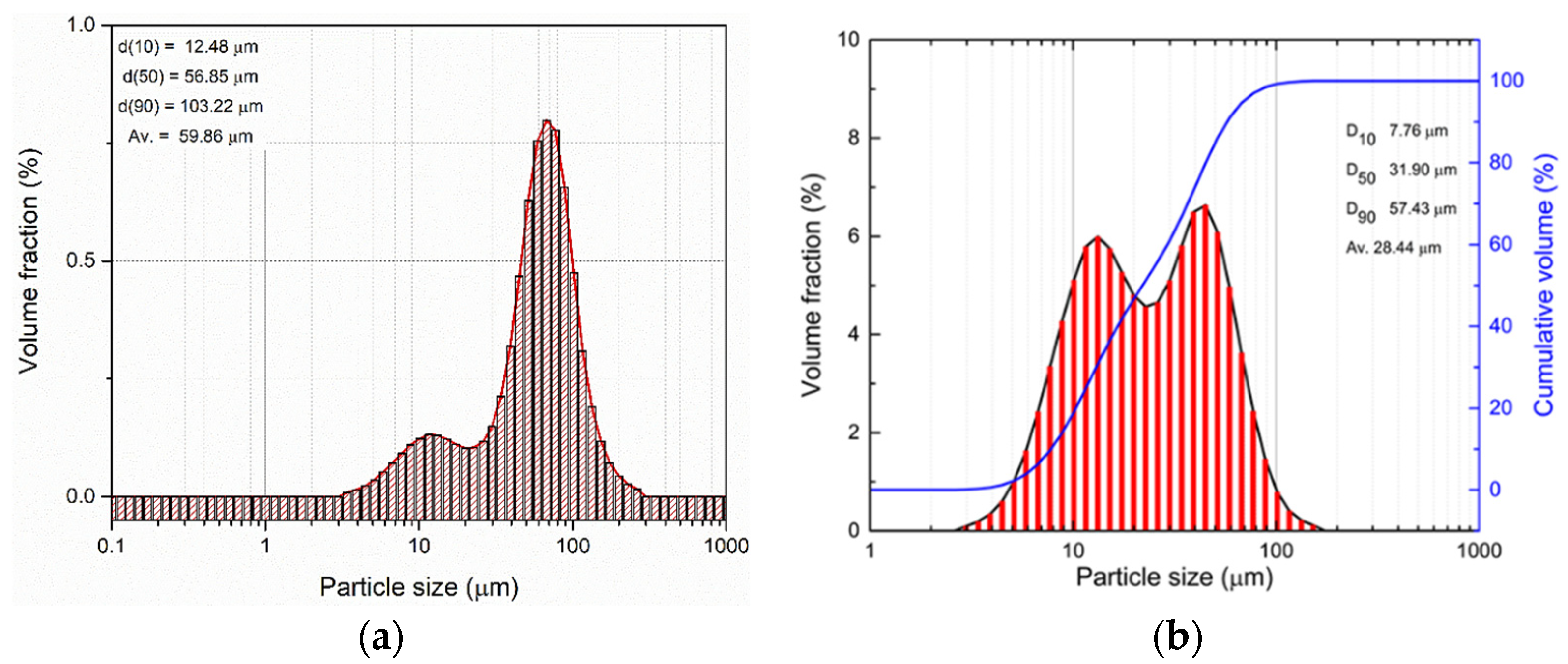
Figure 1a,b displays the differential and cumulative volume percentages of the particle size distribution Ti3AlC2. As can be observed in Image 1a, the feedstock powder distribution is bimodal and polydisperse with the average particles size between 10 and 100 µm, with an average size of 60 μm. After sieving the coarser constituents were removed and the average dimension of the particle is around 30 µm (Figure 1b).
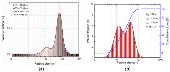
Figure 1.
Particle size distribution for Ti3AlC2 powder (a) before and (b) after sieving.
Table 4 and Table 5 list the results for density measured by Helium pycnometry and specific surface areas measured by BET, and also the O:H:N content in the feedstock powder.
Table 4.
BET analysis and Helium pycnometry for Ti3AlC2 powder.
Table 5.
O:N:H content.
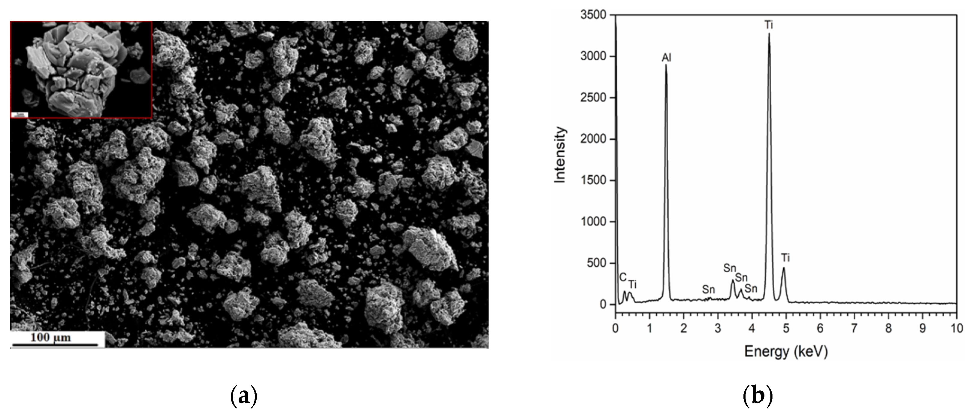
As displayed in Figure 2, the particles exhibit both a coarse and fine lamellar structure, comprising a mix of smaller and larger particles. Some of the particles already show deformation, cracks, and fracture sites along with internal laminates. The EDS spectra reveal the presence of tin (Sn), which was probably introduced as a phase stabilizer in the Ti-Al-C system, to obtain single-phase Ti3AlC2 and to prevent the impurity formation.
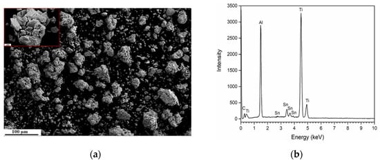
Figure 2.
(a) SEM image of feedstock powder Ti3AlC2 insert: nano-layered structure of a single particle; (b) the corresponding EDS spectra.
3.3. Particle Velocity—Wipe Test Relationship
To find a link between in-flight particle and microstructure characteristics, the particle velocity was measured using a HiWatch CS2 camera (Oseir, Tampere, Finland), which is integrated with an NIR (near-infrared) diode sheet laser to illuminate the “cold” particles and can use up to 2000 m/s. The HiWatch camera detects the scattering phenomena due to particles passing in front of the laser beam as explained by H. Koivuluoto et al. [28]. The particle’s velocity is defined by the trace method: distance of the detected trace of a particle in a single triplet divided by the laser pulse duration. This technique also enables the particle size measurement in the same way by the laser granulometry method. The particle velocity is an important parameter in the deposition of MAX-phase coatings. This parameter can be influenced by the CS deposition parameters (gas temperature and pressure), and powder features (particle diameter, density, and morphology).
Critical velocity (Vcrit) is one of the most important factors in the CS process and depends on the powder and substrate properties. Vcrit is identified as the lowest particle velocity required to create adherence between the powder material and the substrate. Assadi et al. [29] used simulation modelling methods to predict Vcrit in the metals and propose the following equation:
where ρ is the particle density, Ti, Tm, TRef are the initial, melting and reference temperatures, σuts is the ultimate tensile strength.
This work did not take into consideration the particle size, an important factor in determining Vcrit so Schmidt et al. [30] proposed another equation:
where F1 and F2 are constants that represent material-dependent calibration factors, ρp is the density of the particles, and cp is the specific heat capacity of the particle.
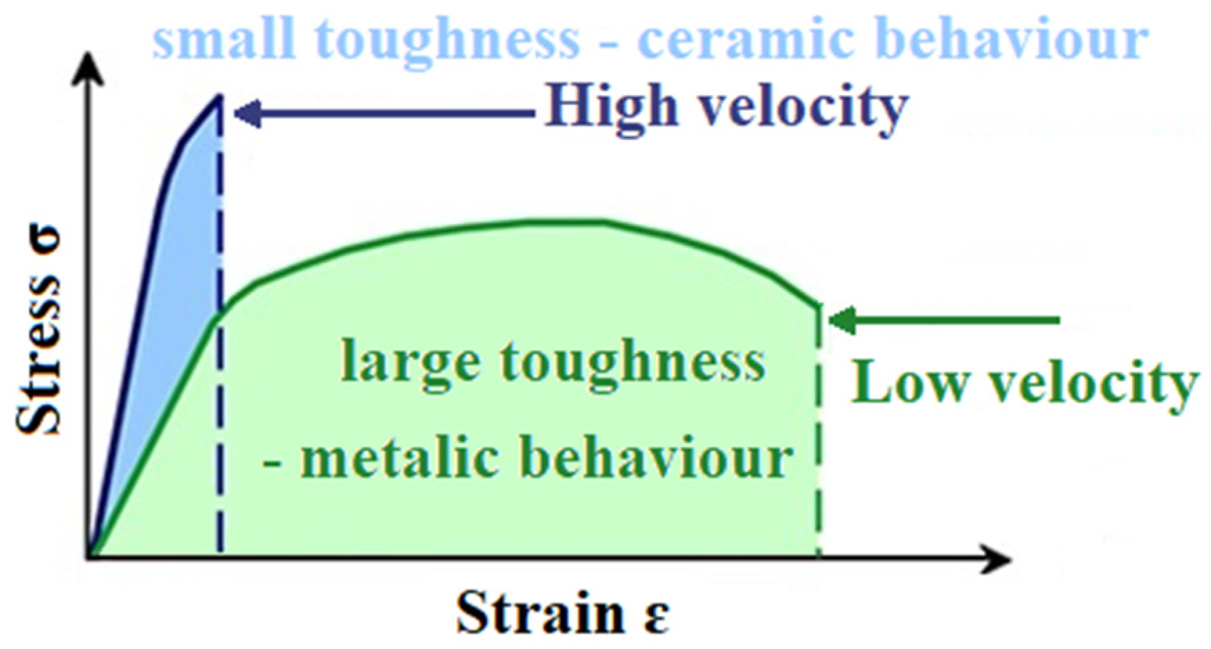
The two semi-empirical equations are in agreement with experimental results for metallic feedstock powder deposition but are not suitable for the MAX phase compounds because of their ceramic–metallic dual character and for that reason they cannot be quantified. Therefore, the CS deposition of Ti3AlC2 is limited in some conditions by brittleness and very limited deformability. The amount of kinetic energy that this material can absorb plastically before deforming or fracturing at contact with the substrate can be correlated with the schematic representation listed in Figure 3.

Figure 3.
Schematic representation of dual character materials in correlation with the particle velocity during the CS deposition process.
The schematic representation in Figure 3 in correlation with our obtained results and the literature [1,16,17,18,19,20,21], is underlining the fact that when the speed of the particle is increased, the ceramic like-behaviour of the MAX phase compound will accentuate the brittle character, leading to fragmentation and no plastic deformation.
S. Suresh et al. [31] emphasize that the metallic particles under high-velocity impacts will induce deformation, leading to heat generation that induces events corresponding to thermal softening and strain hardening. This effect, of thermal softening, plays an important part in the particle–substrate interaction region that leads to high temperature and shear instability localization. If the thermal softening rates surpass the hardening rates, the material will drift in this region [32]. If the size of the incoming particles is larger, the adiabatic shear instability (ASI) increases, and the interaction between particle–substrate and particle–particle is improved [30].
J.O Kliemann et al. [33] studied single ceramic particle impacts and the formation of the first layer onto various metallic substrates. Analyzing the different morphologies of the obtained layer for various substrates, the authors underlined the fact that ASI phenomena occur during the CS deposition. Schmidt et al. [34] give comparable conclusions for deposited TiO2 microparticles onto the Ti substrate. These studies present the dependence of the substrate material characteristics, which exhibits mechanical interlocking or ASI and promotes the ceramic coating build-up.
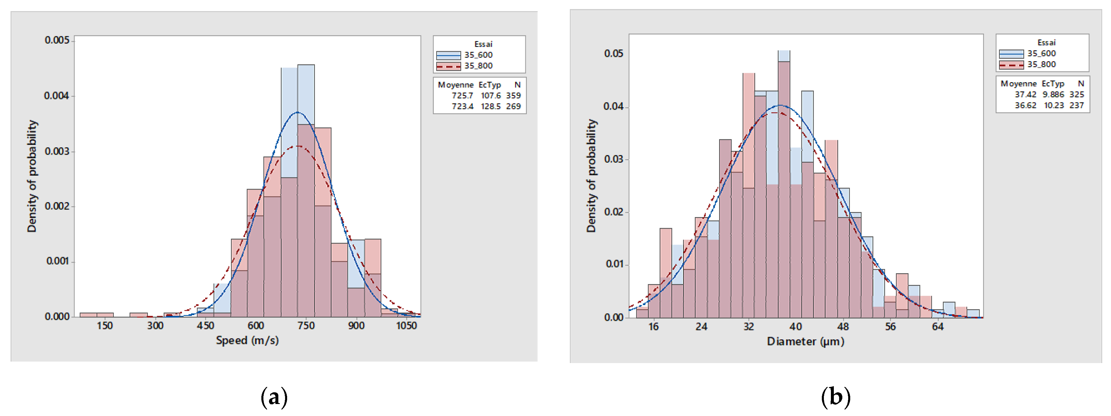
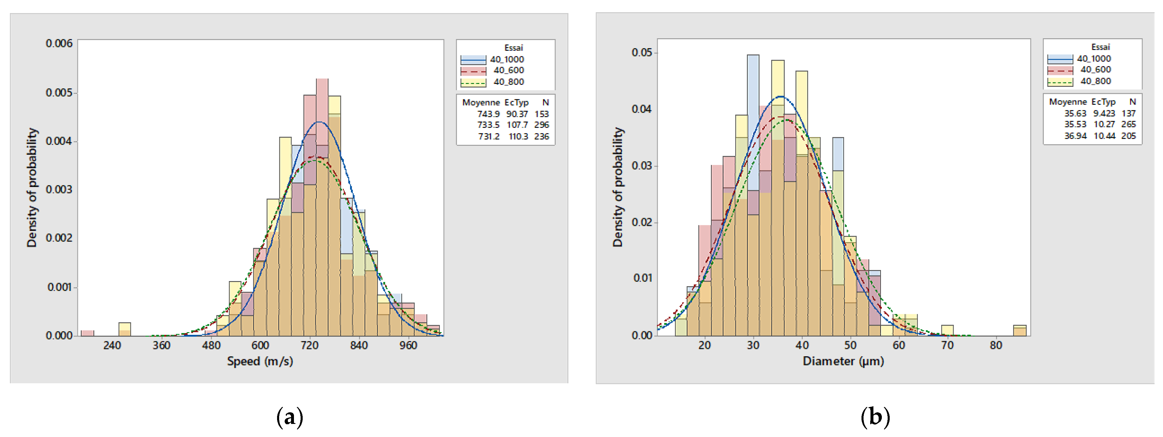
Figure 4, Figure 5 and Figure 6 represent histograms of the Ti3AlC2 particle velocities at a different gas temperatures between (800–1000 °C) in comparison for a selected pressure 3.5, 4 or 5 MPa in the CS process, in correlation with particle diameter density.
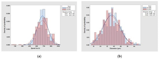
Figure 4.
(a) Ti3AlC2 particle velocities distribution; (b) the corresponding particle density distribution for 3.5 MPa gas pressure and different gas temperatures.
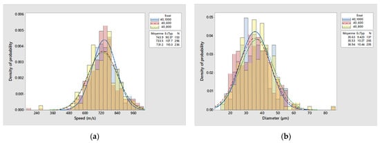
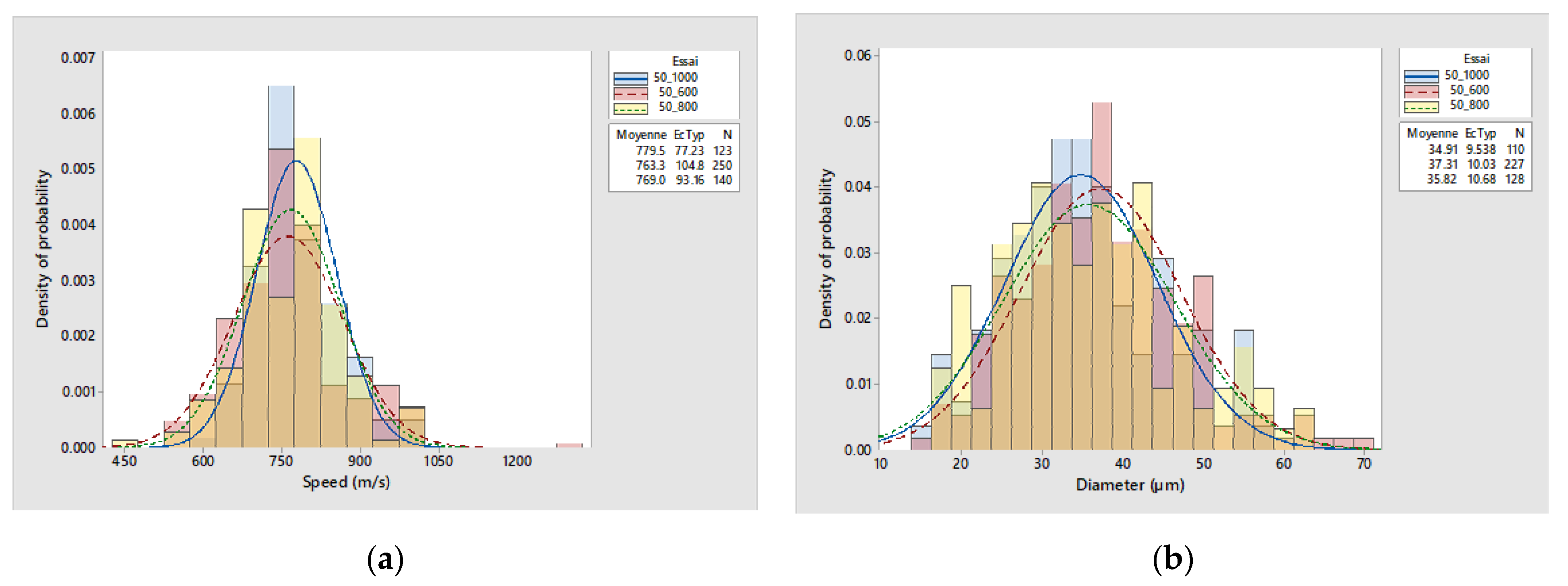
Figure 5.
(a) Ti3AlC2 particle velocities distribution; (b) the corresponding particle density distribution a constant gas pressure of 4 MPa and different gas temperatures.
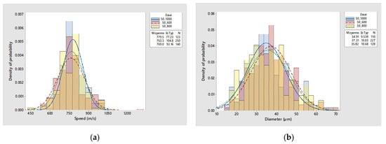
Figure 6.
(a) Ti3AlC2 particle velocities distribution; (b) the corresponding particle density distribution for 5 MPa gas pressure and different gas temperatures.
These measurements linked with the single-particle impact can provide useful information in the Ti3AlC2 coating build-up process, particle deformation and possible erosion by the incoming particle. The data are built on Oseir HiWatch software and contain 500 images with 0.5 ns exposure time. The standard deviation for these measurements is ~50 m/s.
Ti3AlC2 powder presents an irregular shape (as observed in Figure 2), so the ability to flow during the CS process is low and cause clogging. This problem can be avoided by the well-chosen carrier gas and feed rate. The irregular powder particle can achieve greater speed because it can be accelerated more efficiently by the propelled gas due to the higher drag coefficient [35,36]. Different numerical and simulation models have proved that a higher velocity is reached by decreasing the particle size. This is because the carrier gas must work harder to propel the larger particles. Also, by increasing the particle size, the cooling rate will decrease, promoting the bonding process [37]. Smaller particles are strongly influenced by the shock induced at collision with the substrate.
The speed of the particle is higher when the propelled gas pressure increases. When analyzing the SEM images for single-particle impact on TA6V at various particle velocities, it was observed that during the shock-induced dynamic fragmentation, not all fragments present the same shape. When the velocity of the particle is high enough, the particle will undergo initially contained plasticity assisted by confining pressure and the particle size. The impact decreases gradually with the dissipation of the kinetic energy into inhomogeneous plastic deformation, heat energy, and friction [38].
The substrate elastic modulus influences the portion of the flattened, rebounded, and embedded particle. The metallic substrate plastic deformation reduces the initial energy of the particle and promotes mechanical interlock and embedding of the incoming particles. As emphasized by L. Palodhi and H. Singh [39] for metal–metal interaction, if the substrate is softer than the particle then the deformation will be greater for the substrate and the particle will be embedded in it. These results are in agreement with the model proposed by Bae et al. [32]. In the case of ceramic–metal interaction, M.V. Vidaller et al. [40] proved that the substrate’s superior hardness compared to that of the ceramic deposited material would lead to additional deformation of splats and better adhesion strength. Goldbaum et al. [41] correlated the splat’s adhesion strength with the velocity of the particles. Higher incoming particle velocity gives higher strain rates and higher deformation.
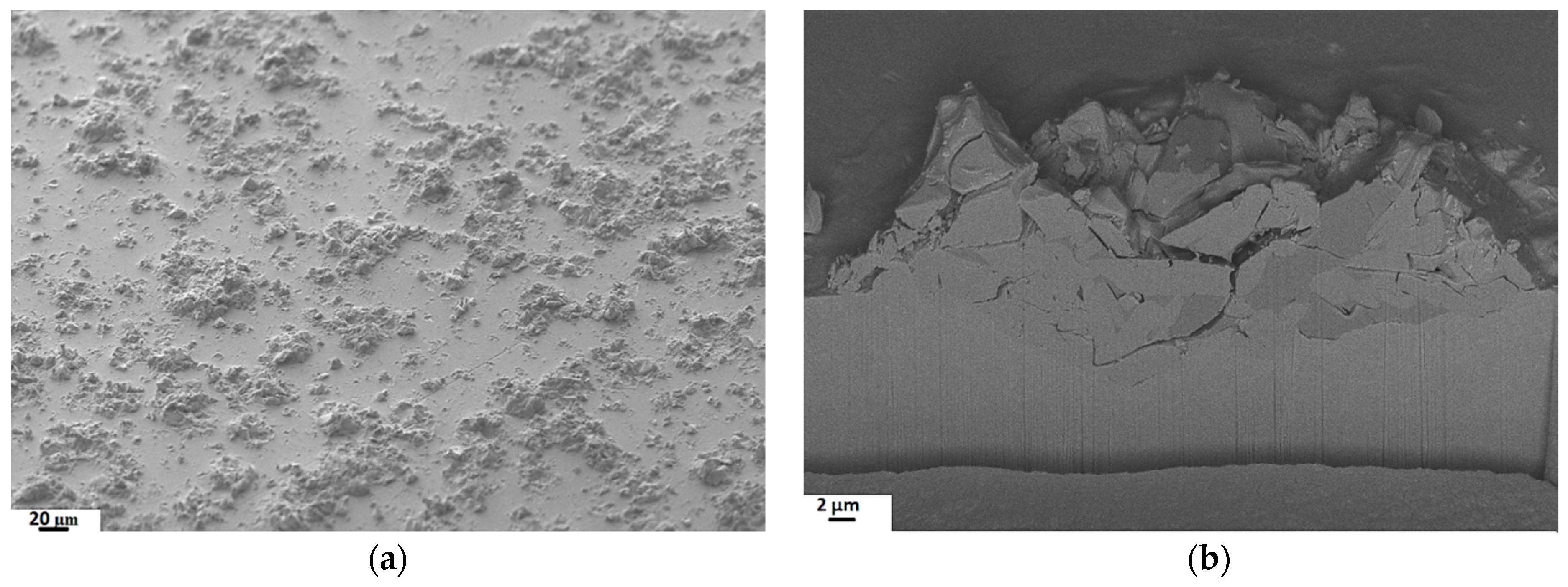
To observe the dual character and understand the MAX phase-metal interaction, single-particle impact with different strength substrates has been performed at a constant particle velocity of ~730 m/s. This study was performed on a polished substrate to examine the interaction and understand adhesion behaviour, which is challenging to identify only from coating microstructure.
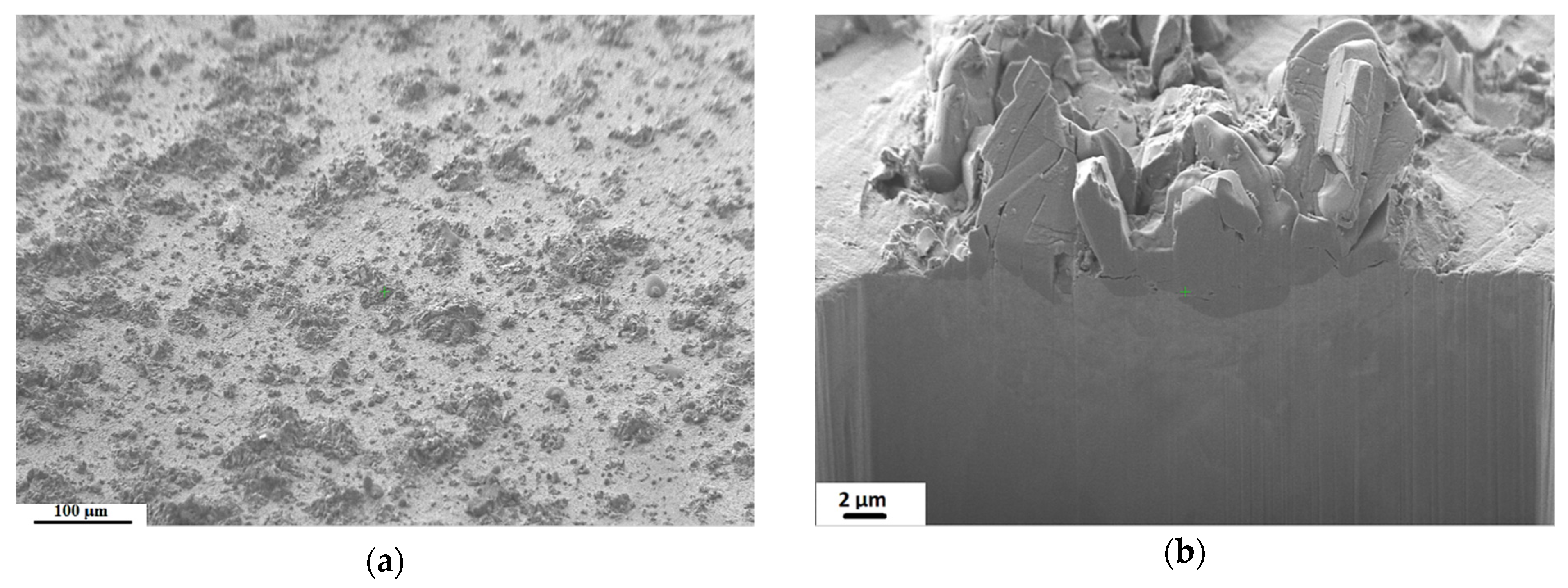
As can be observed in Figure 7, Figure 8 and Figure 9, the SEM images revealed that the particle remains in a solid state and presents distinct types of particle–substrate interactions. The crater deepness increases by decreasing the substrate hardness, because of the higher powder hardness. Ti3AlC2 particles are more embedded in the Al substrates (Figure 9b) compared with TA6V (Figure 7b) and SS (Figure 8b), and no significant fragmentation is observed because of the substrate plastic deformation. The smaller particle presented in Image 9b on the left side had a higher velocity due to the lower mass and was completely embedded in the Al substrate.
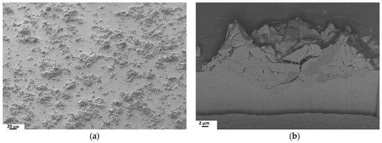
Figure 7.
SEM images of Ti3AlC2 sprayed particles at ~730 m/s on TA6V: (a) top view; (b) FIB cross-section.

Figure 8.
SEM images of Ti3AlC2 sprayed particles at ~730 m/s on SS: (a) top view, (b) FIB cross-section.
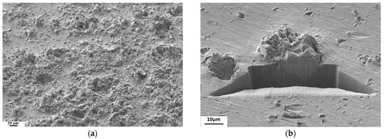
Figure 9.
SEM images of Ti3AlC2 sprayed particles at ~730 m/s on Al: (a) top view, (b) FIB cross-section.
In the case of the harder substrates, such as TA6V, the particle adheres to the substrate and exhibits similar features to feedstock powder with cracks and fracture sites, as highlighted in Figure 7b. The impact of the particles onto a hard and high-strength substrate is more severe and encourages ceramic-like behaviour. The impact on SS substrate (Figure 8) promotes less fragmentation of the particle, due to a smaller mismatch of the elastic modulus of Ti3AlC2 and SS, with a metal–metal behaviour characteristic interaction.
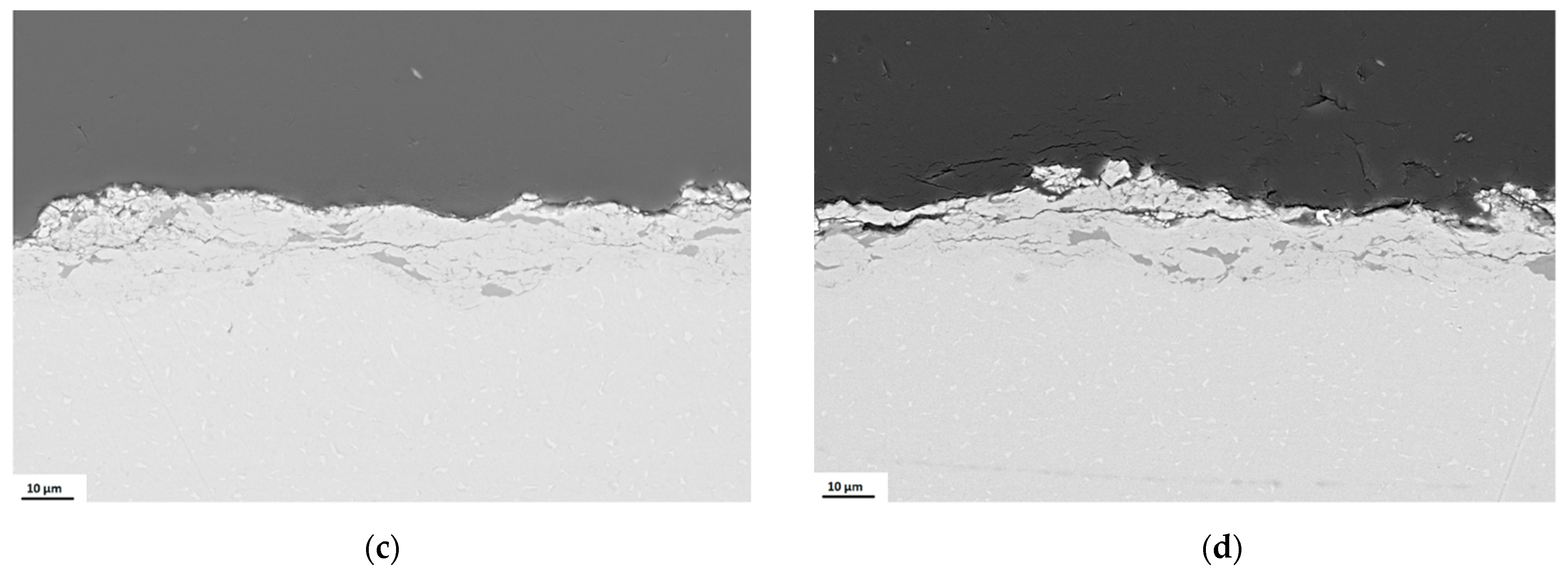
For the Ti3AlC2 particles’ lowest velocity, of ~723 m/s, the metallic behaviour is predominant and their interaction with the TA6V substrate creates a weak bond but limits the coating build-up (Figure 10a). Increasing the velocity up to ~780 m/s, the ceramic behaviour is highlighted, and the kinetic energy is mostly consumed by fragmentation. Also, at a high velocity, the erosion phenomenon is accentuated, limiting the coating thickness.
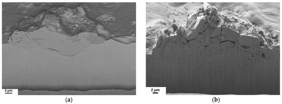
Figure 10.
SEM images of Ti3AlC2 sprayed particles at: (a) ~723 m/s; (b) ~780 m/s on TA6V.
3.4. Coating Microstructure
It is rather challenging to deposit Ti3AlC2–MAX phase compounds as they present highly anisotropic deformation and internal delamination. The unique combination of the nanolaminate layered Ti3AlC2 dual character is given by the Ti-Al sheets that have metallic character alternating with the Ti-C sheets having covalent character. To further comprehend the coating build-up process and the influence of Ti3AlC2 dual character, the CS deposition was performed at varied particle velocity, that corresponds to different gas pressure and temperature. TA6V substrate was used to create the MAX phase coatings. The substrate roughness before the deposition was around 1 µm. Table 1 presents the properties of this substrate. The roughness of the coatings was situated between 4.6 and 5.1 µm, a value comparable with the results obtained by other authors [11]. Due to the plastic deformation of this ductile substrate, the Ti3AlC2 particles will be embedded in the substrate and the first layer will be easily deposited. Due to the high particle velocity, the impact with the substrate will produce a relatively rough coating/substrate interface.
The ceramic character will be more accentuated with the increase of particle velocity, as the next layer is constructed (Figure 11a–d). The particle–particle interaction follows the first layer topography. The adhesion between the first and second layer presents horizontal inter-splat cracks, produced by the absence of adhesion between particles through the deposition process. This elongated porosity is common to ceramic thermal spray deposition [42]. Further build-up layers are limited by the transversal cracks, and the incoming particles will erode or rebound. Therefore, the coating thickness is restricted to less than ~50 µm. The gas temperature enhances the powder particles’ thermal input, slightly increasing the growth of cohesive coatings.
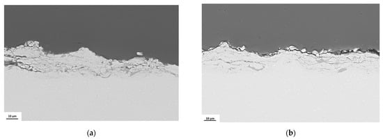
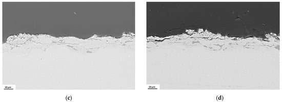
Figure 11.
SEM micrographs of Ti3AlC2 coating obtained at: (a) ~723 m/s; (b) 734 m/s; (c) 743 m/s; (d) 769 m/s on TA6V.
When the particle speed is lower than 723 m/s, cracks and fragmentation are present in all the coatings. This fact can be attributed to weaker particle embedding into the substrate, followed by brittle ceramic–ceramic interaction (Figure 11a).
The strain rate will improve with the increase of the particle speed as the energy dissipated into heat (Figure 11b–d). By enhancing the local temperature, the thermal softening will modify the MAX phase material’s capacity to spread shear forces and eventually the softening process will lead to strain hardening.
The apparition of kink bands, the fragmentation, and the arrangement in the MAX phases due to the hysteretic nonlinear elastic behaviour upon high particle velocity (more than 780 m/s) obstruct the coating build-up (Figure 12a). Top surfaces images revealing these deformations, the apparition of the kinking bands and the cleavage of the nano-layered structure are presented in Figure 12b.
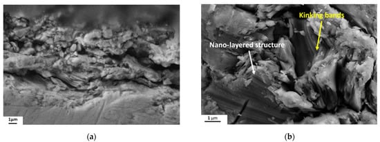
Figure 12.
SEM images of Ti3AlC2 coatings deposited at ~780 m/s: (a) cross-section; (b) top-view SEM image at 10 K magnification that shows the kink bands and the deformation of the nano-layered structure of the Ti3AlC2 particles.
As mentioned before, the dual character of the MAX-phase compound makes difficult the calculation of the critical velocity, but the window of deposition for Ti3AlC2 can be assessed from the obtained SEM images and correspond to values situated between (734 ÷ 769) m/s.
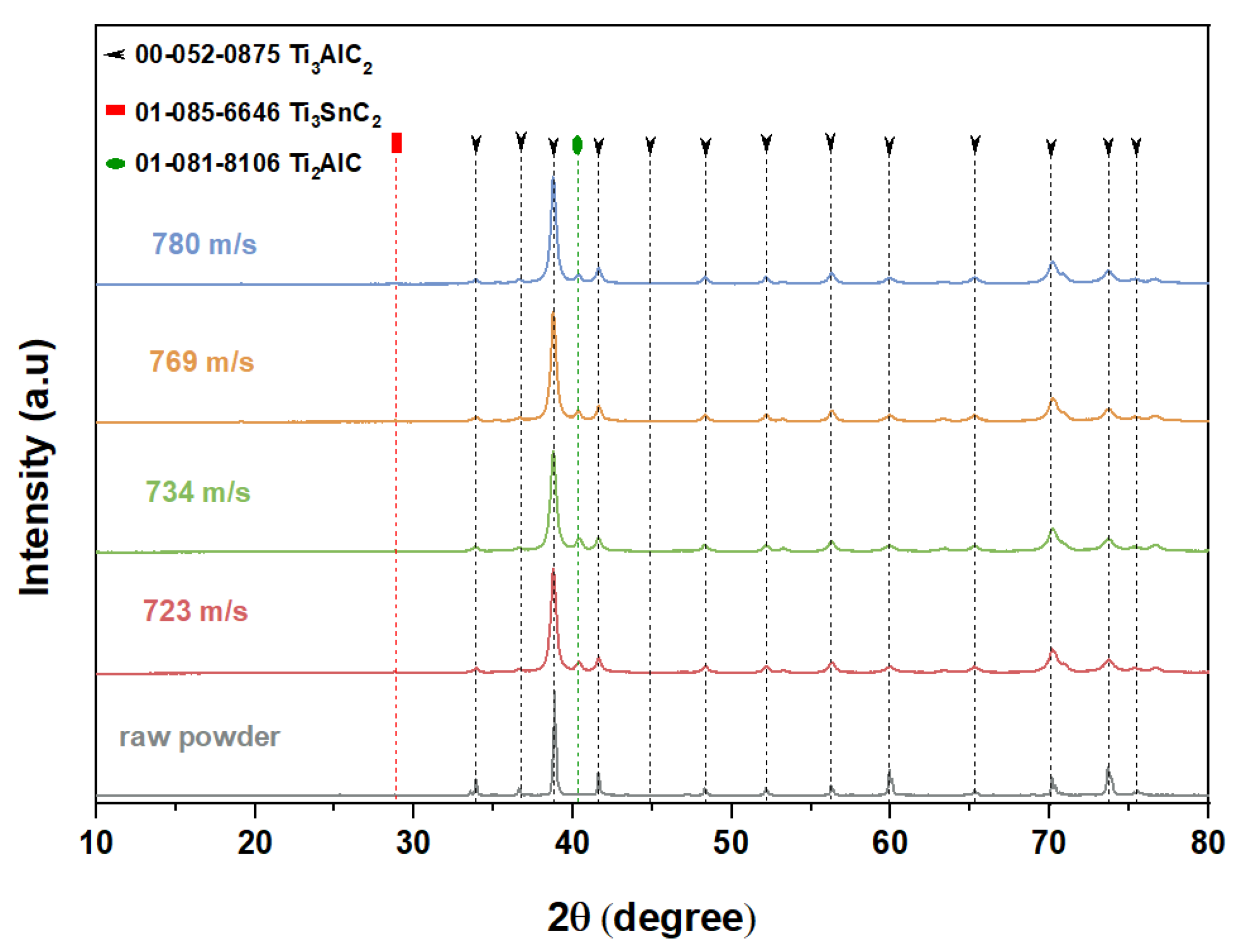
To investigate if phase transformations of the feedstock Ti3AlC2 powder occur during the CS deposition process, XRD analysis was performed for the presented coatings. In Figure 13, XRD spectra of cold sprayed coatings are presented, which exhibit a nearly identical pattern as the feedstock powder. The spectra are in agreement with the data provided by the International Centre for Diffraction Data (ICDD) numbers 52-0875 for Ti3AlC2 and 85-6646 for Ti3SnC2, showing that no significant crystallographic modification occurred during the deposition process, with the MAX phase coatings keeping the same hexagonal P6_3/mmc space group. The analysis proved that the structure was preserved in the coatings without any significant phase transformation. The diffractograms of Ti3AlC2 coatings indicates a minimal contribution from Ti2AlC at 2θ = 40° (006) and no other peaks related to this phase were observed, proving the fact that no significant phase transformation occurs during spraying. Also, the absence of TiO2 and Al2O3 phases in the XRD pattern emphasize that no early stages of oxidation of Ti3AlC2 coatings take place during the CS process. The microstructural changes induced by CS, due to the ballistic impact, can be estimated by XRD. For all the deposition parameters, the XRD pattern shows a reduced intensity and a broadening of the peaks. More specifically, the diffraction peaks exhibit a broadening and/or a shift as a function of the velocity at the impact, highlighting a grain refinement of the microstructure and/or internal induced strains linked to the dislocation density. The crystallite size (D) was evaluated using the Scherrer equation [43]. The results show the effective refinement of the microstructure by applying CS. The crystallite size decreases from 40.3 nm for the feedstock powder down to ~14 nm for all the coatings.
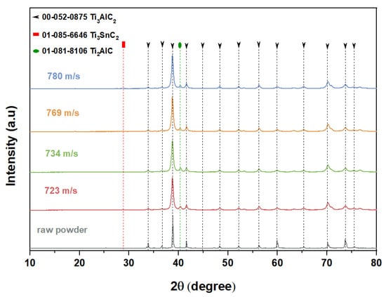
Figure 13.
XRD patterns of the Ti3AlC2 feedstock powder and coatings were obtained at different particle velocities in the CS process.
4. Conclusions
The deposition of MAX phase compounds by CS is rather challenging because they present highly anisotropic deformation and internal delamination beside the dual ceramic–metallic character. Therefore, this work was also focused on the progress on MAX-phase coating build-up by CS, revealing the difficulty in defining particle critical velocity as a consequence of the dual character material behaviour.
Complementary with the limited up-to-date literature, the pioneering deposition of Ti3AlC2 emphasizes the ceramic–metallic character influenced by the supersonic particle deposition and by the mechanical properties of both substrate and compound. The single-particle studies reveal an accentuated ceramic-like behaviour of the 312 MAX phase compound, highlighting the brittle character at higher velocity impact. The dual character of the MAX phase nano-layered structure is revealed when the particle reaches sufficient kinetic energy to undergo plastic deformation (metallic like-behaviour) or fragmentation (ceramic like-behaviour). In both cases, the particles adhere to the substrate, regardless of the used type, but the thickness and the build-up of the coating are influenced by the particle kinetic energy and the mechanical properties of the substrate.
In our studies focused on the Ti3AlC2 deposition on TA6V, we observed that for higher pressure rate, the particles’ speed is increased, leading to better cohesion between particles. No deterioration or coating oxidation was observed up to 1000 °C process gas temperatures. The XRD patterns of the coating show the characteristic peaks of the Ti3AlC2 phase. SEM images of Ti3AlC2 coatings are dense and present low porosity on all substrates. The microstructure is rather homogenous and does not present significant cracks for the coatings obtained at different pressures. The interfaces between the substrate and the coating are well-bonded along with the entire deposition. Also, no cracks or delamination are presented at the interface.
Author Contributions
Conceptualization, P.S. and A.D.; methodology, A.I. and C.P.; software, A.I. and V.B.; validation, A.I., P.S., V.B., P.D., C.P. and A.D.; formal analysis, C.P. and P.S.; investigation, V.B. and P.D.; resources, P.S.; data curation, C.P.; writing—original draft, A.I. and C.P.; writing—review & editing, A.D.; visualization, C.P.; supervision, P.S. and A.D.; project administration, P.S.; funding acquisition, A.D. All authors have read and agreed to the published version of the manuscript.
Funding
This research was funded by SAFRAN, grant number BI 787089/LSP 190147.
Institutional Review Board Statement
Not applicable.
Informed Consent Statement
Not applicable.
Data Availability Statement
Not applicable.
Acknowledgments
The authors give thanks to Hanna Myalska for the initial support at the start of the project, and to Nicolas Le Sausse, Simon Bonebeau and Geoffroy Rivaud for their technical support in carrying out experiments throughout the project.
Conflicts of Interest
The authors declare no conflict of interest. The funders had no role in the design of the study; in the collection, analyses, or interpretation of data; in the writing of the manuscript, or in the decision to publish the results.
References
- Barsoum, M.W.; Radovic, M. Elastic and mechanical properties of the MAX phases. Annu. Rev. Mater. Res. 2011, 41, 195–227. [Google Scholar] [CrossRef]
- Barsoum, M.W. MAX Phases: Properties of Machinable Ternary Carbides and Nitrides; John Wiley & Sons: Singapore, 2013. [Google Scholar]
- Magnuson, M.; Mattesini, M. Chemical bonding and electronic-structure in MAX phases as viewed by X-ray spectroscopy and density functional theory. Thin Solid Films 2017, 621, 108–130. [Google Scholar] [CrossRef]
- Jeitschko, W.; Nowotny, H.; Benesovsky, F. Kohlen-stoffhaltige ternare verbindungen (H-Phase). Monatsh Chem. 1963, 94, 672–676. [Google Scholar] [CrossRef]
- Drouelle, E.; Brunet, V.; Cormier, J.; Villechaise, P.; Sallot, P.; Naimi, F.; Bernard, F.; Dubois, S. Oxidation resistance of Ti3AlC2 and Ti3Al0.8Sn0.2C2 MAX phases: A comparison. J. Am. Ceram. Soc. 2019, 103, 1270–1280. [Google Scholar] [CrossRef]
- Barsoum, M.W.; El-Raghy, T. Synthesis and characterization of a remarkable ceramic: Ti3SiC2. J. Am. Ceram. Soc. 1996, 79, 1953–1956. [Google Scholar] [CrossRef]
- Low, I.M. Advances in Science and Technology of Mn+1AXn Phases, 1st ed.; Woodhead Publishing: Sawston, UK, 2012. [Google Scholar]
- Wilhelmsson, O.; Palmquist, J.-P.; Nyberg, T.; Jansson, U. Deposition of Ti2AlC and Ti3AlC2 epitaxial film by magnetron sputtering. Appl. Phys. Lett. 2004, 85, 1066–1068. [Google Scholar] [CrossRef]
- Berger, O. The correlation between structure, multifunctional properties and application of PVD MAX phase coatings. Surf. Eng. 2020, 36, 268–302. [Google Scholar] [CrossRef]
- Piechowiak, M.A.; Henon, J.; Durand-Panteix, O.; Etchegoyen, G.; Coudert, V.; Marchet, P.; Rossignol, F. Growth of dense Ti3SiC2 MAX phase films elaborated at room temperature by aerosol deposition method. J. Eur. Ceram. Soc. 2014, 34, 1063–1072. [Google Scholar] [CrossRef]
- Markocsan, N.; Manitsas, D.; Jiang, J.; Björklund, S. MAX-phase coatings produced by thermal spraying. J. Superhard Mater. 2017, 39, 355–364. [Google Scholar] [CrossRef]
- Knight, R.; Barsoum, M.W. Method of Applying Corrosion, Oxidation and/or Wear-Resistant Coatings. U.S. Patent 6,497,922 B2, 4 October 2001. [Google Scholar]
- Sonestedt, M.; Frodelius, J.; Palmquist, J.-P.; Högberg, H.; Hultman, L.; Stiller, K. Microstructure of high velocity oxy-fuel sprayed Ti2AlC coatings. J. Mater. Sci. 2010, 45, 2760–2769. [Google Scholar] [CrossRef]
- Berwyn, S.A.; Strock, C.W.; Sharon, J.A.; Klecka, M.A.; Nardi, A.T. Cold Spray Manufacturing of MAXIMET Composites. U.S. Patent 0230288 A1, 27 April 2016. [Google Scholar]
- Moridi, A.; Hassani-Gangaraj, S.M.; Guagliano, M.; Dao, M. Cold spray coating: Review of material systems and future perspectives. Surf. Eng. 2014, 36, 369–395. [Google Scholar] [CrossRef]
- Gutzmann, H.; Gärtner, F.; Höche, D.; Blawert, C.; Klassen, T. Cold spraying of Ti2AlC MAX-phase coatings. J. Therm. Spray Technol. 2013, 22, 406–412. [Google Scholar] [CrossRef]
- Rech, S.; Surpi, A.; Vezzù, S.; Patelli, A.; Trentin, A.; Glor, J.; Frodelius, J.; Hultman, L.; Eklund, P. Cold-spray deposition of Ti2AlC coatings. Vacuum 2013, 94, 69–73. [Google Scholar] [CrossRef] [Green Version]
- Maier, R.; Garcia-Diaz, B.L.; Hauch, B.; Olson, L.C.; Sindelar, R.L.; Sridharan, K. Cold spray deposition of Ti2AlC coatings for improved nuclear fuel cladding. J. Nucl. Mater. 2015, 466, 712–717. [Google Scholar] [CrossRef]
- Loganathan, A.; Sahu, A.; Rudolf, C.; Zhang, C.; Rengifo, S.; Laha, T.; Boesl, B.; Agarwal, A. Multi-scale tribological and nanomechanical behavior of cold sprayed Ti2AlC MAX phase coating. Surf. Coat. Technol. 2018, 334, 384–393. [Google Scholar] [CrossRef]
- Go, T.; Sohn, Y.J.; Mauer, G.; Vaßen, R.; Gonzalez-Julian, J. Cold spray deposition of Cr2AlC MAX phase for coatings and bond-coat layers. J. Eur. Ceram. Soc. 2019, 39, 860–867. [Google Scholar] [CrossRef]
- Elsenberg, A.; Busato, M.; Gärtner, F.; List, A.; Bruera, A.; Bolelli, G.; Lusvarghi, L.; Klassen, T. Influence of MAX-phase deformability on coating formation by cold spraying. J. Therm. Spray Tech. 2021, 30, 617–642. [Google Scholar] [CrossRef]
- Santos da Silva, F.; Cinca, N.; Dosta, S.; Cano, I.G.; Guilemany, J.M.; Benedetti, A.V. Cold gas spray coatings: Basic principles, corrosion protection and applications. Eclética Quím. J. 2017, 42, 9–32. [Google Scholar] [CrossRef] [Green Version]
- Singh, H.; Sidhu, T.S.; Kalsi, S.B.S.; Karthikeyan, J. Development of cold spray from innovation to emerging future coating technology. J. Braz. Soc. Mech. Sci. Eng. 2013, 35, 231–245. [Google Scholar] [CrossRef]
- Raoelison, R.N.; Verdy, C.; Liao, H. Cold gas dynamic spray additive manufacturing today: Deposit possibilities, technological solutions and viable applications. Mater. Des. 2017, 133, 266–287. [Google Scholar] [CrossRef]
- The, U.S. Develops Soft Biosensor Patch That Can Comprehensively Monitor Vital Signs of Children-a Significant Advancement in Ti3AlC2 Ceramic Material. Available online: https://www.mis-asia.com/news/The-U-S--develops-soft-biosensor-patch-that-can-comprehensively-monitor-vital-signs-of-children-a-significant-advancement-in-Ti3AlC2-Ceramic-Material-150.html (accessed on 23 May 2021).
- Chen, K.; Qiu, N.; Deng, Q.; Kang, M.H.; Yang, H.; Baek, J.U.; Koh, Y.H.; Du, S.; Huang, Q.; Kim, H.E. Cytocompatibility of Ti3AlC2, Ti3SiC2, and Ti2AlN: In vitro tests and first-principles calculations. ACS Biomater. Sci. Eng. 2017, 3, 2293–2301. [Google Scholar] [CrossRef]
- Ng, W.H.K.; Gnanakumar, E.S.; Batyrev, E.; Sharma, S.K.; Pujari, P.K.; Greer, H.F.; Zhou, W.; Sakidja, R.; Rothenberg, G.; Barsoum, M.W.; et al. The Ti3AlC2 MAX phase as an efficient catalyst for oxidative dehydrogenation of n-butane. Angew. Chem. 2018, 130, 1501–1506. [Google Scholar] [CrossRef] [Green Version]
- Koivuluoto, H.; Larjo, J.; Marini, D.; Pulci, G.; Marra, F. Cold-sprayed al6061 coatings: Online spray monitoring and influence of process parameters on coating properties. Coatings 2020, 10, 348. [Google Scholar] [CrossRef] [Green Version]
- Assadi, H.; Gärtner, F.; Stoltenhoff, T.; Kreye, H. Bonding mechanism in cold gas spraying. Acta Mater. 2003, 51, 4379–4394. [Google Scholar] [CrossRef]
- Schmidt, T.; Gärtner, F.; Assadi, H.; Kreye, H. Development of a generalized parameter window for cold spray deposition. Acta Mater. 2006, 54, 729–742. [Google Scholar] [CrossRef]
- Suresh, S.; Lee, S.-W.; Aindow, M.; Brody, H.D.; Champagne, V.K., Jr.; Dongare, A.M. Unraveling the mesoscale evolution of microstructure during supersonic impact of aluminum powder particles. Sci. Rep. 2018, 8, 1–13. [Google Scholar] [CrossRef]
- Bae, G.; Xiong, Y.; Kumar, S.; Kang, K.; Lee, C. General aspects of interface bonding in kinetic sprayed coatings. Acta Mater. 2008, 56, 4858–4868. [Google Scholar] [CrossRef]
- Kliemann, J.O.; Gutzmann, H.; Gärtner, F.; Hübner, H.; Borchers, C.; Klassen, T. Formation of cold-sprayed ceramic titanium dioxide layers on metal surfaces. J. Therm. Spray Technol. 2010, 20, 292–298. [Google Scholar] [CrossRef] [Green Version]
- Schmidt, K.; Buhl, S.; Davoudi, N.; Godard, C.; Merz, R.; Raid, I.; Kerscher, E.; Kopnarski, M.; Müller-Renno, C.; Ripperger, S.; et al. Ti surface modification by cold spraying with TiO2 microparticles. Surf. Coat. Technol. 2017, 309, 749–758. [Google Scholar] [CrossRef]
- Munagala, V.N.V.; Akinyi, V.; Vo, P.; Chromik, R.R. Influence of powder morphology and microstructure on the cold spray and mechanical properties of Ti6Al4V coatings. J. Therm. Spray Technol. 2018, 27, 827–842. [Google Scholar] [CrossRef]
- Wong, W.; Vo, P.; Irissou, E.; Ryabinin, A.N.; Legoux, J.-G.; Yue, S. Effect of particle morphology and size distribution on cold-sprayed pure titanium coatings. J. Therm. Spray Technol. 2013, 22, 1140–1153. [Google Scholar] [CrossRef]
- Walker, M. Microstructure and bonding mechanisms in cold spray coatings. Mater. Sci. Technol. 2018, 34, 2057–2077. [Google Scholar] [CrossRef]
- Park, H.; Kim, J.; Lee, C. Dynamic fragmentation process and fragment microstructure evolution of alumina particles in a vacuum kinetic spraying system. Scr. Mater. 2015, 108, 72–75. [Google Scholar] [CrossRef]
- Palodhi, L.; Singh, H. On the dependence of critical velocity on the material properties during cold spray process. J. Therm. Spray Technol. 2020, 29, 1863–1875. [Google Scholar] [CrossRef]
- Vidaller, M.V.; List, A.; Gaertner, F.; Klassen, T.; Dosta, S.; Guilemany, J.M. Single impact bonding of cold sprayed Ti-6Al-4V powders on different substrates. J. Therm. Spray Technol. 2015, 4, 644–658. [Google Scholar] [CrossRef]
- Goldbaum, D.; Shockley, J.M.; Chromik, R.R.; Rezaeian, A.; Yue, S.; Legoux, J.-G.; Irissou, E. The effect of deposition conditions on adhesion strength of Ti and Ti6Al4V cold spray splats. J. Therm. Spray Technol. 2012, 21, 288–303. [Google Scholar] [CrossRef]
- Gonzalez-Julian, J.; Mauer, G.; Sebold, D.; Mack, D.E.; Vassen, R. Cr2AlC MAX phase as bond coat for thermal barrier coatings: Processing, testing under thermal gradient loading, and future challenges. J. Am.Ceram. Soc. 2020, 103, 2362–2375. [Google Scholar] [CrossRef] [Green Version]
- Bobzin, K.; Lugscheider, E.; Maes, M.; Immich, P.; Bolz, S. Grain size evaluation of pulsed TiAlN nanocomposite coatings for cutting tools. Thin Solid Films 2007, 515, 3681–3684. [Google Scholar] [CrossRef]


Publisher’s Note: MDPI stays neutral with regard to jurisdictional claims in published maps and institutional affiliations. |
© 2021 by the authors. Licensee MDPI, Basel, Switzerland. This article is an open access article distributed under the terms and conditions of the Creative Commons Attribution (CC BY) license (https://creativecommons.org/licenses/by/4.0/).