Article

Wear and Corrosion Resistance of CoCrFeNiSiMoW Medium-Entropy Alloy Coatings on Q235 Steel

School of Materials Science and Engineering, Jiangsu University of Science and Technology, Zhenjiang 212003, China
*
Authors to whom correspondence should be addressed.
Coatings 2021, 11(9), 1053; https://doi.org/10.3390/coatings11091053
Submission received: 7 July 2021 / Revised: 9 August 2021 / Accepted: 28 August 2021 / Published: 31 August 2021
(This article belongs to the Special Issue Corrosion and Degradation of Materials)

Abstract

:
CoCrFeNiSiMoW medium-entropy alloy coatings (MEACs) were fabricated by plasma-arc surfacing welding on Q235 steel. The microstructures and mechanical properties of CoCrFeNiSiMoW MEACs were studied. CoCrFeNiSiMoW MEACs are made from a mixture of NiCrCoMo cubic (FCC) solid solution phase, (Fe, Ni), Mo1.24Ni0.76, and CoCx phases by XRD analysis. The average hardness values of the one- and two-layer CoCrFeNiSiMoW MEACs obtained were 186 ± 1.56 and 198 ± 1.78 HV, respectively. Compared with the one-layer CoCrFeNiSiMoW coating, the two-layer coating has a better wear performance due to its higher hardness. Its corrosion resistance is better because of its higher Ni content.

1. Introduction

Every year, the economic losses caused by the wear and corrosion of metal materials are high. At the same time, the wear and corrosion of metal materials also affect the quality of industrial products, which contribute to a poor market image for enterprises, and will inevitably bring challenges to the realization of economic benefits for enterprises. It is particularly important to prepare wear- and corrosion-resistant coatings on the surface of the material. Due to the increasing demand of modern industry for wear- and corrosion-resistant coatings, researchers continue to explore new coating materials.
High- and medium-entropy alloys (HEAs and MEAs, respectively) possess a list of excellent properties, such as excellent strength and hardness [1,2], outstanding wear performance [3], and good corrosion resistance [4,5]. When HEA and MEA were initially proposed, they were considered to be composed of at least five elements. After an in-depth study of HEAs and MEAs, some quaternary alloys not equal to or close to equal atomic percentages, ranging from 5% to 35%, were also determined to be considered HEAs and MEAs [6]. It provided the new idea to fabricate alloy coatings with good wear and corrosion resistance due to their high content of multiple corrosion-resistant elements [7]. Many types of research about high- and medium-entropy alloy coatings (HEACs and MEACs, respectively) have been conducted. Feng et al. [8] researched the corrosion properties of laser cladding CrCoNi MEACs and found they had better corrosion resistance than SS304. Zhao et al. [9] studied the fabrication and friction properties of an AlFeCrCo MEAC on a magnesium alloy using a resistance seam-welding method. The results showed that the AlFeCrCo MEAC has a better wear performance than the substrate. Tian et al. [10] synthesized a CrMnFeCoNi HEAC with a thickness of 180 μm on Q235 steel using a mechanical alloying method and found it had better corrosion resistance than Q235 steel in a 3.5% NaCl solution. A Al2CrFeNiMox HEAC was fabricated by laser cladding, and its wear resistance was improved because of the properties of Mo [11]. Xu et al. [12] fabricated a CoCrFeNiTiMo HEAC and studied its corrosion resistance. Lloyd et al. [13] studied the effects of the elements Cr, Mo, and W, on the passive film of Ni-Cr-Mo (W) alloys in acidic solutions. Their results showed that high Cr-alloys form thicker oxides with a core-shell structure consisting of an inner Cr-Ni oxide layer and an outer Mo/W oxide in a 0.1 M H2SO4 + 1.0 M NaCl solution. Some studies have shown that Mo can also alter mechanical properties and the corrosion resistance of HEAs because it can change the morphology, the segregation behavior of elements, and the phase structure [14,15]. In addition, Cr can improve the wear and corrosion resistance of materials, and Ni can help improve the corrosion performance in acidic solutions.
The methods of fabricating HEACs include laser cladding [16], magnetron sputtering [17], plasma spraying [18], and more. Laser cladding technology is a common technique to fabricate wear-resistant coatings. In the process of laser cladding, the heat source is a laser, and the cladding material is a powder material. The cladding efficiency is relatively low and the price of power is high. Compared to laser cladding, plasma-arc surfacing technology uses welding wire as a cladding material and a plasma arc as a heat source, which has a relatively higher efficiency and is a more economical preparation method of cladding coating. In this process, the dilution effect of the base metal affects the mechanical properties of coatings. The Fe element from the base metal can change the proportion of elements in coatings so that the HEA/MEA coatings can be obtained by making full use of the dilution and selecting the appropriate welding wire. To study the effects of this change on the microstructure and properties, one- and two-layer coatings were prepared.
Hastelloy X (HX) alloy contains Cr, Ni, and Mo, and it was selected to fabricate HEACs/MEACs by plasma-arc surfacing welding in this study. HX has been widely studied in high temperature conditions because it has extraordinary properties, such as formability, oxidation resistance, and mechanical properties in the temperature range of 540–1000 °C [19,20,21]. However, the literature on fabricating HEACs/MEACs with HX and about its wear and corrosion resistance at room temperature is plentiful.
In this work, one- and two-layer CoCrFeNiSiMoW MEACs were fabricated with HX wire by plasma-arc surfacing welding, and its wear and corrosion resistance were studied.

2. Experimental Details

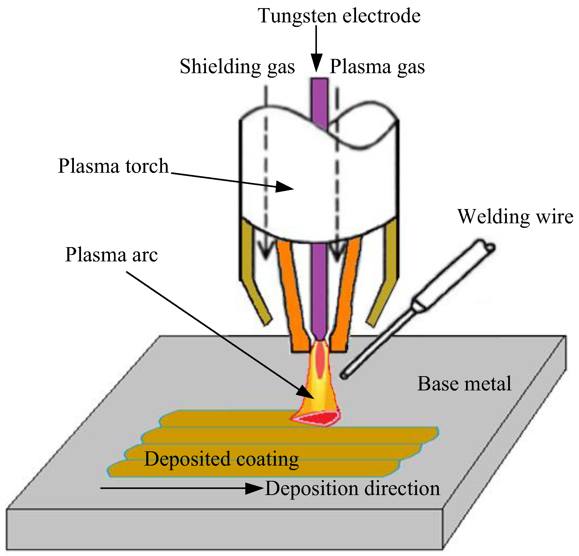
2.1. CoCrFeNiSiMoW Coating Fabrication

Q235 steel was taken as the base metal in this study. Before plasma-arc surfacing welding, the surface of Q235 was ground with 200# sandpaper and cleaned with acetone. The HX wire was used as filling wire to fabricate the coatings. The main elemental compositions of Q235 and HX wire are shown in Table 1.
A Trans Tig5000 Series Digital automatic welding machine (Fronius, Pettenbach, Austria) was adopted to fabricate the coatings. Figure 1 shows a schematic diagram of plasma-arc surfacing welding. First, the non-arc power supply causes the non-arc between the tungsten electrode and the nozzle. Once the non-arc is produced, the plasma gas between the tungsten electrode and the nozzle causes the formation of the path. When the main arc power supply is turned on, the arc will start between the base metal and the tungsten electrode. The main arc is then generated, also known as the transfer arc. Because the current of the main arc is generally large, the energy density of the main arc is also relatively high, which can form a molten pool on the surface of the base metal. Welding wire enters the plasma flame, is melted by the plasma flame, and is deposited on the base metal to form a coating. Protective gas protects the plasma flame from oxidation of the molten pool by oxygen during surfacing welding through a protective gas channel. The direction of the arc movement is the direction of deposition. Due to the influence of dilution, different surfacing layers may affect the performance of the coatings. Two coatings were deposited by HX wire: one was HX1 coating with one layer of HX; the other was HX2 coating with two layers of HX. Table 2 shows the surfacing welding process parameters. Argon, with a purity of 99.99%, was used as a protective gas throughout these processes.

2.2. Microstructure Observation and Hardness Measurement

Square coatings with dimensions of 10 × 10 mm2 were cut and polished for the XRD test, microstructure observation, and hardness measurement.
The main chemical compositions of the HX1 and HX2 coatings were tested by a direct-reading spectrograph with a PAD5500II (Shimadzu, Kyoto, Japan). The crystal structures of CoCrFeNiSiMoW coatings were tested by X-ray diffractometer (XRD, Bruker D8 Advance, Karlsruhe, Germany). The diffraction angle (2θ) ranged from 20° to 90°. The scan rate was 5° per minute with a step size of 0.02°. The microstructures of the coatings were characterized by an optical microscope (Nikon Epiphot 300 model, Tokyo, Japan) and a scanning electron microscope (SU-70 model, Tokyo, Japan) after the coatings were mechanically polished and etched in a 3 wt % HNO3 solution.
A DHV-1000 hardness tester (Shanghai Shangcai Tester Machine Co., LTD., Shanghai, China) was used to measure the surface hardness of the HX1 and HX2 coatings every 0.25 mm with a test load of 500 g and a dwell time of 15 s. These experiments were repeated five times. The test result was the average value of five experiments. The ranges between plus and minus were obtained by calculating the standard deviation of five experimental data. The horizontal axis was the distance, and the vertical axis was the hardness value.

2.3. Wear Measurements

Square coatings with dimensions of 30 × 30 mm2 were cut and polished for a wear resistance test. A dry reciprocating sliding wear test was carried out by the HSR-2M friction tester (Lanzhou Institute of Chemical Physics, Lanzhou, China) at room temperature. A Si3N4 ceramic ball was used as the friction couple, and the working disk was coated in HX1 and HX2. The Si3N4 ball was reciprocated with a stroke length of 5 mm at a sliding speed of 25 mm/s for a duration of 30 min. The loads were chosen to be 20, 30, and 40 N. During the friction testing, the data were transmitted to a computer by the sensor on the loading rod, and the corresponding friction coefficient was calculated. The friction tests were repeated at least five times. The test results are the average of five experiments. After the friction tests, images of wear scars were observed by a laser scanning confocal microscope (LEXT, OLS400 LSCM, Tokyo, Japan) and a scanning electron microscope (SEM, JEOL, JSM-6480, Tokyo, Japan). The wear rates (mm3 N−1·m−1), represented by WS, can be calculated by the following formula [22]:
W S = C A F L
where parameters C, A, F and L, correspond to the width of the wear scar (mm), average wear area of wear loss (mm2), applied load (N), and the distance of sliding friction (mm), respectively.

2.4. Electrochemical Corrosion

An electrochemical corrosion analysis of CoCrFeNiSiMoW coatings was conducted in 3.5% NaCl solution by a CHI600E electrochemical workstation (Wuhan Corrtest Instruments, Corp., Wuhan, China) at room temperature. A three-electrode electrochemical cell, including a saturated calomel reference electrode (SCE), a platinum counter electrode, and a working electrode of coatings of HX1 and HX2, was adopted [23]. The scan rate of the tests was 0.5 mV/s, and the test range was −0.5~1.5 V.

3. Results and Discussion

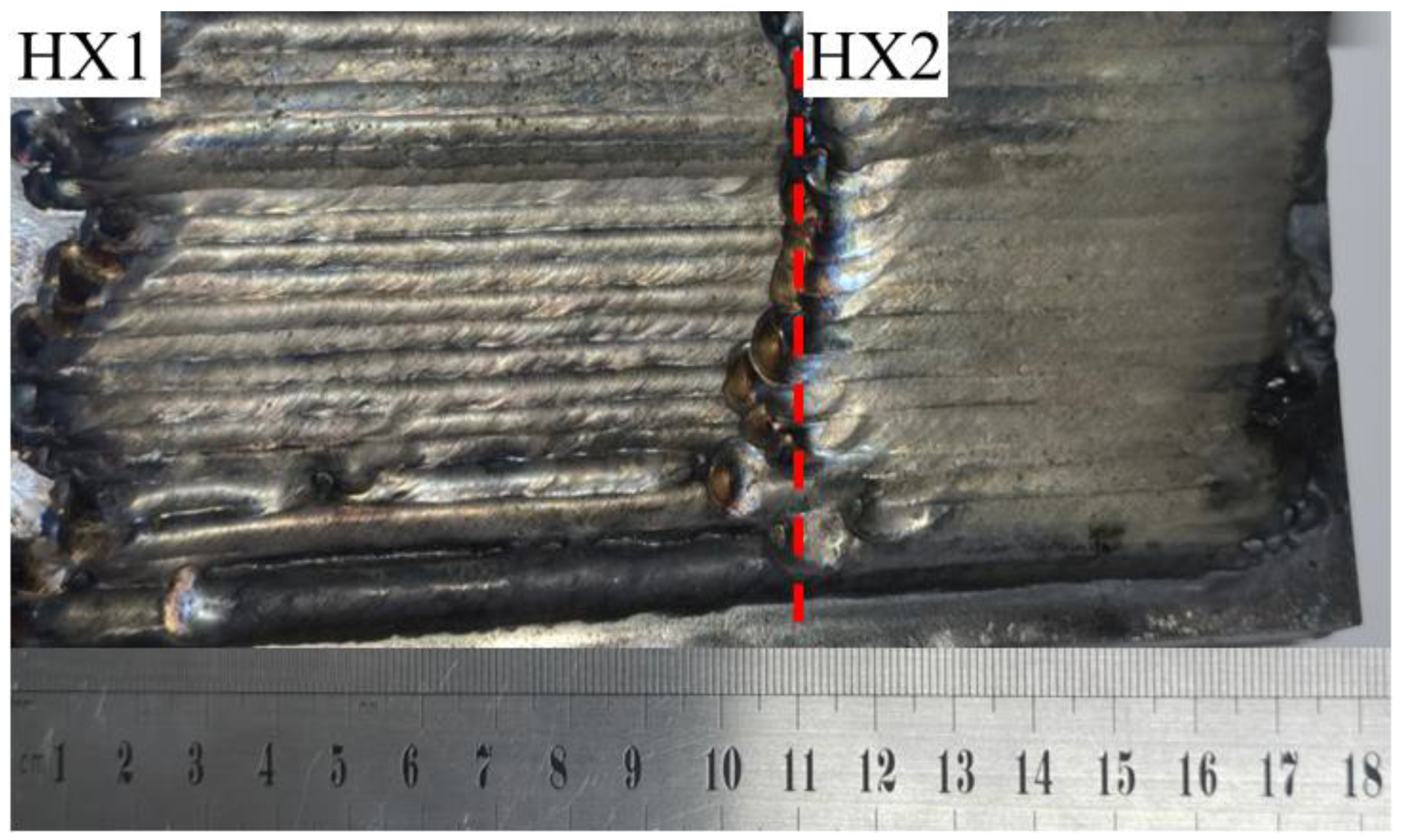
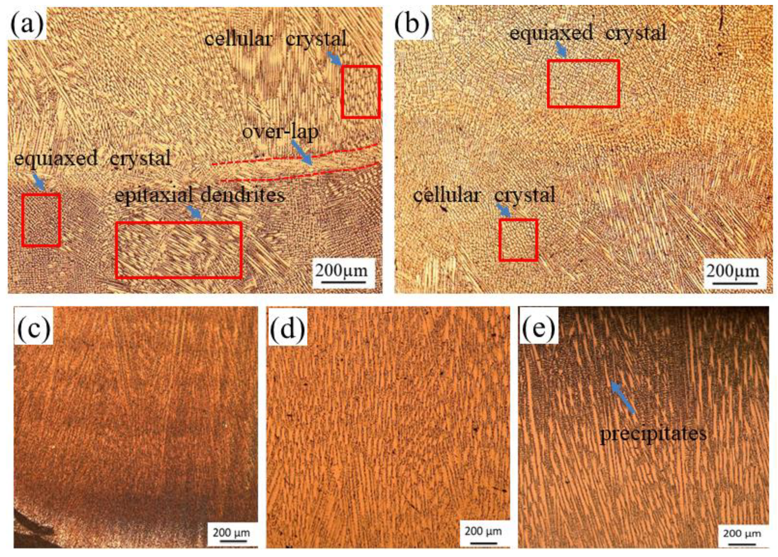
3.1. Morphology Observation
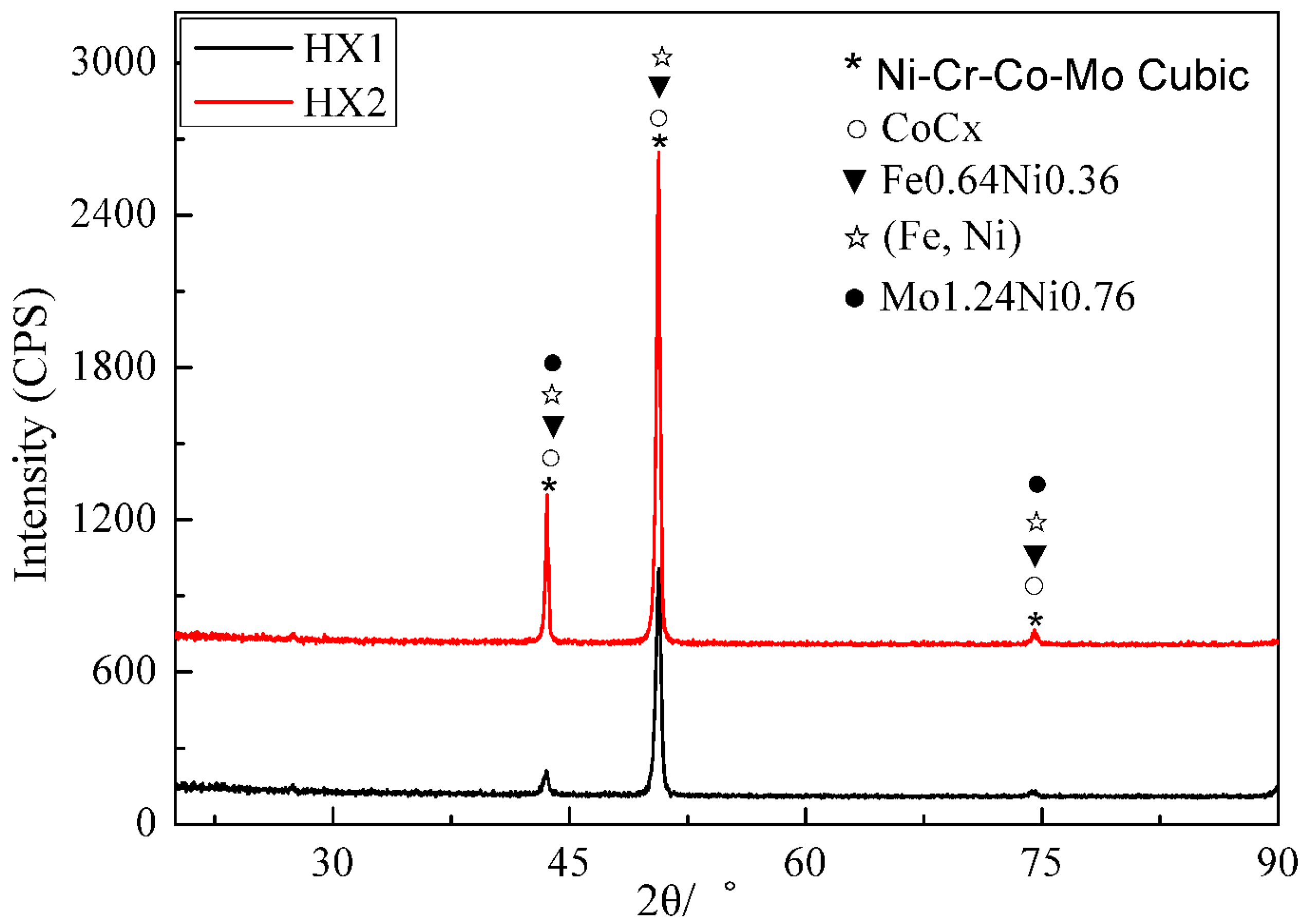
The surface appearance of CoCrFeNiSiMoW coatings after plasma-arc surfacing welding is shown in Figure 2. It is evident that the HX wires were melted sufficiently, and continuous coatings were formed on the Q235 base metal. Each coating had a uniform geometric appearance, and the surface of the HX2 coating was smoother than that of HX1 coating. The overlaps between adjacent welding passes were almost parallel to each other.
Figure 3 shows the optical microstructures of the HX1 and HX2 coatings. From Figure 3a, it can be seen that the microstructure of the HX1 coating contains various forms of equiaxed microstructures, epitaxial dendrites, and cellular crystals. Interface also can be seen in the overlap area between welding passes, which can be attributed to different growth velocities and different growth directions. Figure 3b shows a typical equiaxed microstructure on the surface of the HX2 coating. Figure 3c–e is the microstructure of the cross section of the HX2 coating: the bottom, medium and top, respectively. It can be seen that from the bottom to the top, i.e., the deposition direction, dendrites grew in different directions. There are tiny sedimentary facies between dendrites. These smaller deposits are evenly distributed between dendrites at the bottom and middle. At the top, the dendrites are coarse, and there are more small precipitates of particles between the dendrites. This is due to the sectioning of the epitaxial dendrites growing upward along the deposition direction. Compared with the HX1 coating shown in Figure 3a, the microstructure of the HX2 coating shown in Figure 3b is obviously smaller than that of the HX1 coating, which may lead to the higher hardness of the HX2 coating.

3.2. XRD Analysis

Table 3 shows the main elemental compositions of the HX1 and HX2 coatings. It was shown that they were the CoCrFeNiSiMoW coatings. The entropy value (ΔS) of the coatings can be obtained by Boltzmann’s hypothesis [24]:
Δ S = R [ X 1 l n X 1 + X 2 l n X 2 + X n l n X n ] = R i = 1 n X i l n X i
where R is a gas constant, Xi is the molar ratio of the principal element, and n is the number of mixing elements. According to the value of ΔS, alloys are divided into high-, medium-, and low-entropy alloys. When the value of ΔS is greater than or equal to 1.5 R, it is considered to be a high-entropy alloy. When the value of ΔS is between R and 1.5 R, it is considered to be a medium-entropy alloy. If the value of ΔS is less than R, it is identified as a low-entropy alloy [24].
According to Formula (2), the mixing entropy of the alloying layers’ system can be calculated by the molar fraction of each element. The mixed entropy of the HX1 and HX2 coatings was 1.30 R and 1.28 R, respectively. Therefore, the HX1 and HX2 coatings can be considered CoCrFeNiSiMoW medium-entropy coatings.
From Table 3, it can be seen that the Ni, Cr, Co, W, and Mo contents in the HX2 coating are higher than in the HX1 coating. Ni, Cr, and Co can be formed in solid solution. The elements of W and Mo can solubilize in solid solution, which contributes to solid solution strengthening. The atomic radii of Mo and W are larger than that of the other elements involved, and the solid solubility of the W and Mo in the Ni-Cr-Co solid solution matrix is large. They can cause lattice deformations, resulting in a solid solution, as has been reported previously [25,26]. This may lead to the higher hardness of the HX2 coating compared to the HX1 coating.
The XRD patterns of the HX1 and HX2 coatings are shown in Figure 4. It can be confirmed that the CoCrFeNiSiMoW coatings of HX1 and HX2 display a solution matrix of CoCrFeNiSiMoW cubic phase (FCC), according to JCPDS card number 35-1489. The high mixing entropy effect can effectively reduce the mixing Gibbs free energy, thus promoting the formation of a FCC solid solution during solidification [14]. In addition to the FCC matrix, some weak diffraction peaks were detected. These diffraction peaks correspond to some secondary phases. Their structures are similar to (Fe, Ni), Mo1.24Ni0.76, and CoCx phases, according to JCPDS card numbers 47-1417, 47-1129, and 44-0962, respectively. Compared with the XRD diffraction peak of HX, the peak of the HX2 coating is shifted to the left. The stronger lattice distortion is caused by the higher content of W and Mo in the HX2 coating [27].

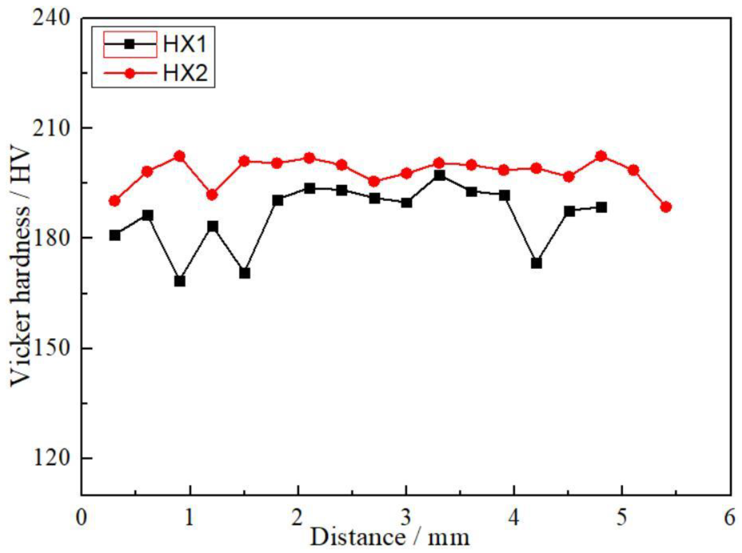
3.3. Hardness of Coatings
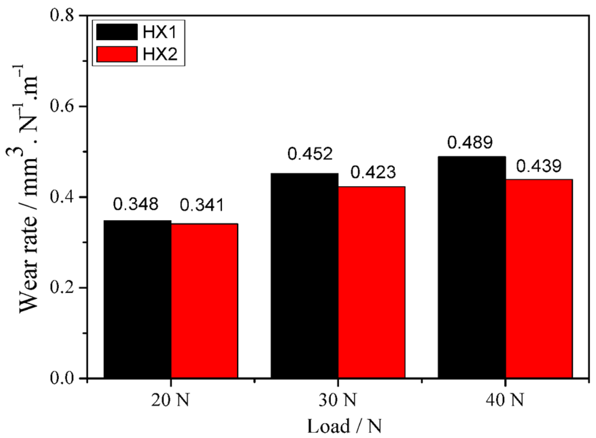
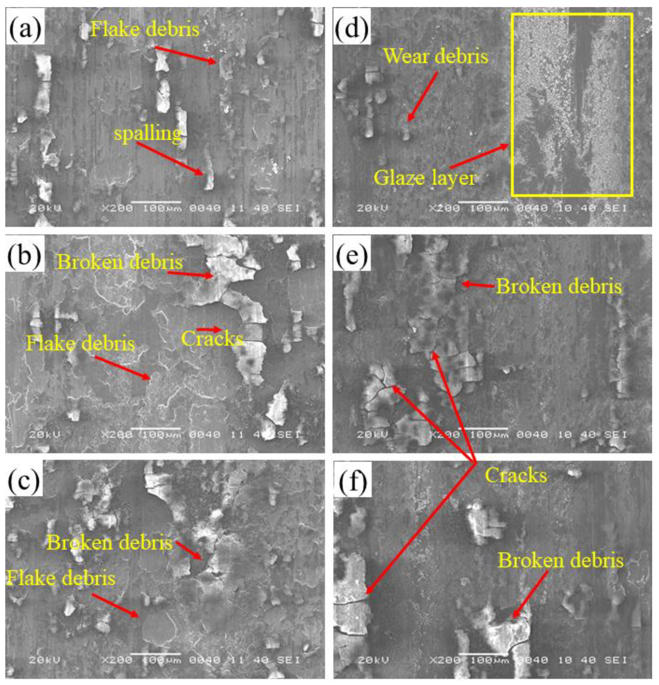
Figure 5 shows the surface hardness profile of the HX1 and HX2 coatings. The hardness values of the HX1 and HX2 coatings fluctuate from 165 to 195 HV and from 192 to 200 HV, with average hardness values of 186 ± 1.56 and 198 ± 1.78 HV, respectively. The hardness of the HX2 coating is higher than that of the HX1 coating. The hardness tests are consistent with the analysis results in Figure 3 and Table 3. Hardness represents the ability of materials to resist residual deformation and anti-failure. In general, the higher the hardness of the material, the better the wear resistance.

3.4. Wear Analysis

Figure 6 represents the change in the friction coefficients of CoCrFeNiSiMoW MEA coatings as a function of wear test time under different loads. During test periods of 150 s, the friction coefficients increased over time, then declined and remained fluctuating. The increase indicates the transition from material intact to material fracture [28]. It also can be seen that the friction coefficient decreased with the increased load. Under the same load, the friction coefficient of the HX2 coating was less than that of the HX1 coating. It indicates that the change of the friction coefficient might relate to the wear mechanism caused by the changing load. The wear mechanism will be further analyzed later in detail.
Figure 7 represents the wear rate of the HX1 and HX2 coatings with increasing loads. The wear rate of the HX1 coating increased from 0.348 to 0.489 mm3∙N−1∙m−1, while the wear rate of the HX2 coating increased from 0.341 to 0.439 mm3∙N−1∙m−1 when the loads increased from 20 to 40 N. This demonstrates that the wear rate increased with increasing loads. Comparing the HX1 and HX2 coatings at a load of 20 N, the wear rates of HX1 and HX2 are 0.348 and 0.341 mm3∙N−1∙m−1, respectively, which is a statistically insignificant difference. This means that the performance of both coatings is similar at a load of 20 N. At a load of 30 or 40 N, the wear rate of HX2 is lower than that of HX1. Wear belongs to the category of contact surface stress, that is, the wear rate under pressure due to the interaction between the surface of the coating and the Si3N4 ball. In this case, the wear resistance of a high hardness coating is better than that of low hardness coating. The test results are consistent with the analysis of the hardness test results.
Figure 8 presents the wear scars of the HX1 and HX2 coatings under different loads. When the applied loads change from 20 to 40 N, it can be seen that the widths of the wear scars of the HX1 and HX2 coatings increase from 1007.60 to 1264.86 μm, and from 982.10 to 1192.85 μm, respectively. The width of the wear scars increases with the increase in applied load. In Figure 8a–c, there is a visibly large quantity of continuous spalling surfaces and some ploughs on the worn surface of the HX1 coating. It indicates that the main wear mechanism of the HX1 coating is adhesion wear, followed by abrasive wear. For the HX2 coating, as shown in Figure 8d–f, there is a large number of grooves and some discontinuous spalling surfaces. It means that the main wear mechanism of the HX2 coating is abrasive wear, followed by adhesion wear.
Figure 9 plots the two-dimensional (2D) profiles of the cross-section of the wear scars under different loads. When the load increased from 20 to 40 N, the depths of the wear scars on the HX1 and HX2 coatings increased from 11.5 to 21.5 μm, and from 10.5 to 20.8 μm, respectively. The width of the wear scar also increased with the increasing load. The wear track depth of the HX1 coating was slightly larger than that of the HX2 coating after sliding wear under the same load. The edges of the HX1 and HX2 coatings became evident due to extrusion with the load increases.
Figure 10a–f shows the worn surface morphology of the HX1 and HX2 coatings examined in detail using SEM after being subjected to sliding wear under different loads. From Figure 10a, it can be seen there were flake debris, spalling from the surface of the HX1 coating, and broken debris under a load of 20 N. When the load increased to 30 N, flake debris, spalling, and broken debris were aggravated, and cracks appeared, as shown in Figure 10b. When the load reached 40 N, the flake debris and surface appalling shown in Figure 10c changed little compared with that shown in Figure 10b. This morphology is consistent with the analysis results in Figure 8a–c. The main wear mechanism of the HX1 coating is adhesion wear, followed by abrasive wear. From Figure 10d, it can be seen there were wear debris and a discontinuous glaze layer on the worn surface of the HX2 coating. Cracks and broken debris appeared, and wear debris was visible on the surface of the HX2 coating, as shown in Figure 10e,f. It indicates that the wear mechanisms of the HX2 coating is adhesion and abrasive wear. The significant fluctuations in the friction coefficients, as shown in Figure 6, are attributable to inhomogeneous distributions of the glaze layer and wear debris.

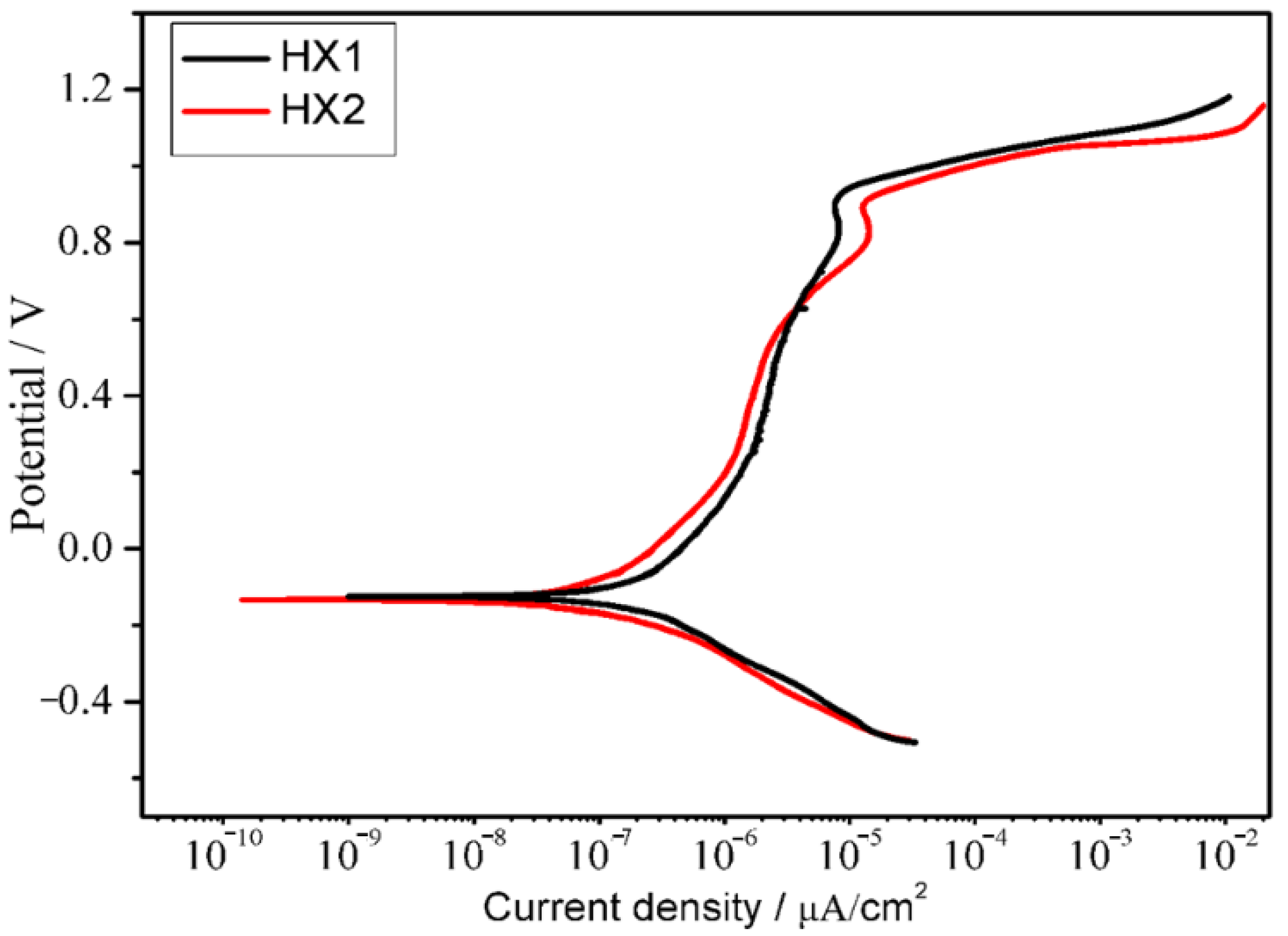
3.5. Electrochemical Corrosion

Figure 11 presents the polarization curve of the CoCrFeNiSiMoW MEACs in a 3.5% NaCl solution. Both MEACs underwent passivation, even though the two MEACs exhibit the same corrosion potential. The corrosion current density of the two coatings increased rapidly when the potential was about 1.0 V and passive corrosion occurred, which can obstruct the corrosion of the coating surface by the 3.5% NaCl solution.
Table 4 shows the free corrosion potential (Ecorr) and the current density (icorr) value, which are determined from the linear portion of the polarization curve by Tafel extrapolation. According to classical electrochemical theory, the free corrosion potential (Ecorr) only represents the thermodynamic trend in the coatings in the corrosion process, while the free corrosion density (Icorr) is caused by the dissolution of the coatings. Therefore, Icorr is more accurate for evaluating corrosion resistance of coatings [29,30]. Compared to the HX1 coating, the HX2 coating has a lower Ecorr and smaller Icorr. It can be concluded that the HX2 coating has better corrosion resistance than the HX1 coating.
Figure 12 shows SEM images of corrosion of the two HX coatings. In Figure 12a, it can be seen that the dendrite core of the HX1 coating and the deposited particles between cellular crystals were corroded, while the dendrite core of the HX2 coating remained intact, and the deposited particles between dendrites were visible, as shown in Figure 12b. On the one hand, this result can be attributed to some large dendrites on the surface of the HX1 coating, as shown in Figure 3a, and the finding that the boundaries between the dendrites maximized the interaction area between the surface of the HX1 coating and the corrosive solution. On the other hand, it can be seen in Table 3 that the HX2 coating contained a higher amount of Ni than the HX1 coating, and Ni has a higher electrochemical potential, which is also beneficial to improving the corrosion resistance of the HX2 coating. The SEM observation results are consistent with the analysis in Figure 11.

4. Conclusions

The CoCrFeNiSiMoW medium-entropy alloy coating was successfully fabricated by plasma-arc surfacing welding.
The CoCrFeNiSiMoW MEACs are a mixture of a NiCrCoMo cubic (FCC) solid solution phase, (Fe, Ni), Mo1.24Ni0.76, and CoCx phases.
The average hardness values of the one-layer and two-layer CoCrFeNiSiMoW MEACs are 186 ± 1.56 and 198 ± 1.78 HV, respectively. The two-layer coating has a higher hardness because of a higher content of W and Mo on the surface of the coating. The radii of W and Mo atoms are larger than those of the other elements in the coating, and they solubilize in the Ni-Cr-Co solid solution and cause lattice deformation, resulting in solid solution strengthening.
At a load of 20 N, the one-lay coating and two-layer coatings have similar wear resistance. At loads of 30 and 40 N, the wear resistance of the two-layer coating is better than that of a one-layer coating because of the higher hardness of the two-layer coating.
The corrosion resistance of the two-layer CoCrFeNiSiMoW coating is better than that of a one-layer coating because the two-layer coating contains a higher amount of Ni than a one-layer coating, and Ni has a higher electrochemical potential, which is also beneficial to improving the corrosion resistance, which is evident in the two-layer coating.

Author Contributions

Project administration, Q.H.; data curation, X.W.; formal analysis, X.S., F.F. and Z.T. All authors have read and agreed to the published version of the manuscript.

Funding

The National Science Foundation of China (Nos. 51205176 and 51675249) supported this research.

Institutional Review Board Statement

Not applicable.

Informed Consent Statement

Not applicable.

Data Availability Statement

The data used to support the findings of this study are available from the corresponding authors upon request.

Conflicts of Interest

The authors declare no conflict of interest.

References

  1. Zhang, Z.T.; Axinte, E.; Ge, W.J.; Shang, C.Y.; Wang, Y. Microstructure, mechanical properties and corrosion resistance of CuZrY/Al, Ti, Hf series high-entropy alloys. Mater. Des. 2016, 108, 106–113. [Google Scholar] [CrossRef]
  2. Wu, P.H.; Peng, Z.; Liu, N.; Niu, M.Y.; Zhu, Z.X.; Wang, X.J. The effect of Mn content on the microstructure and properties of CoCrCu0.1Fe0.15Mo1.5MnxNi. Mater. Trans. 2016, 57, 5–8. [Google Scholar] [CrossRef] [Green Version]
  3. Chuang, M.H.; Tsai, M.H.; Wang, W.R.; Lin, S.J.; Yeh, J.W. Microstructure and wear behavior of AlxCo1.5CrFeNi1.5Tiy high-entropy alloys. Acta Mater. 2011, 59, 6308–6317. [Google Scholar] [CrossRef]
  4. Ye, Q.F.; Feng, K.; Li, Z.G.; Lu, F.G.; Li, R.F.; Huang, J.; Wu, Y.X. Microstructure and corrosion properties of CrMnFeCoNi high entropy alloy coating. Appl. Surf. Sci. 2017, 396, 1420–1426. [Google Scholar] [CrossRef]
  5. Nair, R.B.; Arora, H.S.; Mukherjee, S.; Singh, S.; Singh, H.; Grewal, H.S. Exceptionally high cavitation erosion and corrosion resistance of a high entropy alloy. Ultrason. Sonochem. 2018, 41, 252–260. [Google Scholar] [CrossRef] [PubMed]
  6. Li, Z.M.; Pradeep, K.G.; Deng, Y.; Raabe, D.; Tasan, C.C. Metastable high-entropy dual-phase alloys overcome the strength-ductility trade-off. Nature 2016, 534, 227–230. [Google Scholar] [CrossRef] [PubMed]
  7. Qiu, Y.; Thomas, S.; Gibson, M.A.; Fraser, H.L.; Pohl, K.; Birbilis, N. Microstructure and corrosion properties of the low-density single- phase compositionally complex alloy AlTiVCr. Corros. Sci. 2018, 133, 386–396. [Google Scholar] [CrossRef]
  8. Feng, K.; Zhang, Y.; Li, Z.G.; Yao, C.W.; Yao, L.; Fan, C.Y. Corrosion properties of laser cladded CrCoNi medium entropy alloy coating. Surf. Coat. Technol. 2020, 397, 126004. [Google Scholar] [CrossRef]
  9. Zhao, D.C.; Yamaguchi, T.; Tusbasa, D.J.; Wang, W.Q. Fabrication and friction properties of the AlFeCrCo medium-entropy alloy coating on magnesium alloy. Mater. Des. 2020, 193, 108872. [Google Scholar] [CrossRef]
  10. Tian, Y.; Lu, C.Y.; Shen, Y.F.; Feng, X.M. Microstructure and corrosion property of CrMnFeCoNi high entropy alloy coating on Q235 base metal via mechanical alloying method. Surf. Interfaces. 2019, 15, 135–140. [Google Scholar] [CrossRef]
  11. Wu, W.; Jiang, L.; Jiang, H.; Pan, X.M.; Cao, Z.Q. Phase evolution and properties of Al2CrFeNiMox high-entropy alloys coatings by laser cladding. J. Therm. Spray Technol. 2015, 24, 1333–1340. [Google Scholar] [CrossRef]
  12. Xu, J.; Peng, S.; Li, Z.Y.; Jiang, S.Y.; Xie, Z.H.; Munroe, P.; Lu, H. Remarkable cavitation erosion-corrosion resistance of CoCrFeNiTiMo high-entropy alloy coatings. Corros. Sci. 2021, 190, 109663. [Google Scholar] [CrossRef]
  13. Lloyd, A.C.; Noël, J.J.; Mclntyre, S.; Shoesmith, D.W. Cr, Mo and W alloying additions in Ni and their effect on passivity. Electrochim. Acta 2004, 49, 3015–3027. [Google Scholar] [CrossRef]
  14. Shun, T.T.; Chang, L.Y.; Shiu, M.H. Microstructure and mechanical properties of multiprincipal component CoCrFeNiMox alloys. Mater. Charact. 2012, 70, 63–67. [Google Scholar] [CrossRef]
  15. Hsu, Y.J.; Chiang, W.C.; Wu, J.K. Corrosion behavior of FeCoNiCrCux high-entropy alloys in 3.5% sodium chloride solution. Mater. Chem. Phys. 2005, 92, 112–117. [Google Scholar] [CrossRef]
  16. Li, Y.Z.; Shi, Y. Microhardness, wear resistance, and corrosion resistance of Al0.8CrFeCoNiCu high-entropy alloy coatings on aluminum by laser cladding. Mater. Res. Express. 2021, 7, 026504. [Google Scholar]
  17. Chen, T.K.; Shun, T.T.; Yeh, J.W.; Wong, M.S. Nanostructured nitride films of multi-element high-entropy alloys by reactive DC sputtering. Surf. Coat. Technol. 2004, 188–189, 193–200. [Google Scholar] [CrossRef]
  18. Zeng, Q.F.; Xu, Y.T. A comparative study on the tribocorrosion behaviors of AlFeCrNiMo high entropy alloy coating and 304 stainless steel. Mater. Today Commun. 2020, 24, 101261. [Google Scholar] [CrossRef]
  19. Wang, F. Mechanical property study on rapid additive layer manufacture Hastelloy X alloy by selective laser melting technology. Int. J. Adv. Manuf. Technol. 2011, 58, 545–551. [Google Scholar] [CrossRef]
  20. Zhao, J.C.; Larsen, M.; Ravikumar, V. Phase precipitation and time temperature-transformation diagram of Hastelloy X. Mater. Sci. Eng. A. 2000, 293, 112–119. [Google Scholar] [CrossRef]
  21. Blue, C.A.; Blue, R.A.; Lin, R.Y.; Lei, J.F.; Williams, W.D. Joining of Hastelloy X to Inconel 718 using an infrared process. J. Mater. Process. Technol. 1996, 58, 32–38. [Google Scholar] [CrossRef]
  22. Qiao, Y.X.; Sheng, S.L.; Zhang, L.M.; Chen, J.; Zheng, Z.B. Friction and wear behaviors of a high nitrogen austenitic stainless steel Fe-19Cr-15Mn-0.66N. J. Min. Metall. Sect. B Metall. 2021, 57, 285–293. [Google Scholar]
  23. Qiao, Y.X.; Xu, D.K.; Wang, S.; Ma, Y.J.; Chen, J.; Wang, Y.X.; Zhou, H.L. Effect of hydrogen charging on microstructural evolution and corrosion behavior of Ti-4Al-2V-1Mo-1Fe alloy. J. Mater. Sci. Technol. 2021, 60, 168–176. [Google Scholar] [CrossRef]
  24. Sharma, P.; Dwivedi, V.K.; Dwivedi, S.P. Development of high entropy alloys: A review. Mater. Today Proc. 2021, 43, 502–509. [Google Scholar] [CrossRef]
  25. Liu, N.; Ding, W.; Wang, X.J.; Du, J.J.; Liu, L.X. Microstructure evolution and phase formation of Fe25Ni25CoxMoy Multi-principal component alloys. Metall. Mater. Trans. A 2020, 51, 2990–2997. [Google Scholar] [CrossRef]
  26. Ding, W.; Liu, N.; Fan, J.C.; Cao, J.; Wang, X.J. Diffusion bonding of copper and titanium with an interlayer of CoCrFeMnNi high-entropy alloy. Intermetallics 2021, 129, 107027. [Google Scholar] [CrossRef]
  27. Lin, K.H.; Tseng, C.M.; Chueh, C.C.; Chang, S.Y.; Lo, Y.C.; Wang, C.C.; Lin, S.J.; Yeh, J.W. Different lattice distortion effects on the tensile properties of Ni-W dilute solutions and CrFeNi and CoCrFeMnNi concentrated solutions. SSRN Electron. J. 2021. [Google Scholar] [CrossRef]
  28. Xi, Y.T.; Bai, Y.Y.; Gao, K.W.; Pang, X.L.; Yang, H.S.; Yan, L.C.; Volinsky, A.A. Residual stress and microstructure effects on mechanical, tribological and electrical properties of TiN coating on 304 stainless steel. Ceram. Int. 2018, 44, 15851–15858. [Google Scholar] [CrossRef]
  29. Li, Y.Z.; Shi, Y. Microhardness, wear resistance, and corrosion resistance of AlxCrFeCoNiCu high-entropy alloy coatings on aluminum y laser cladding. Opt. Laser Technol. 2021, 134, 106632. [Google Scholar] [CrossRef]
  30. Qiao, Y.X.; Chen, Y.; Li, L.L.; Chen, J.; Emori, W.; Wang, X.J.; Yang, L.; Zhou, H.L.; Song, G.; Naik, N.; et al. Corrosion behavior of a nickel-free high-nitrogen stainless steel with hydrogen charging. JOM 2021, 73, 1165–1172. [Google Scholar] [CrossRef]
Figure 1. A schematic diagram of plasma-arc surfacing welding.
Coatings 11 01053 g001
Figure 2. The surface appearance of CoCrFeNiSiMoW coating after plasma-arc surfacing welding. HX1 is a one-layer coating, and HX2 is a two-layer coating.
Coatings 11 01053 g002
Figure 3. Optical microstructures of the HX1 and HX2 coatings: (a) the microstructure of the surface of the HX1 coating; (b) the microstructure of the surface of HX2 coating; (ce) the microstructures of the bottom, medium, and top cross-sections of the HX2 coating, respectively.
Coatings 11 01053 g003
Figure 4. XRD patterns of the HX1 and HX2 coatings.
Coatings 11 01053 g004
Figure 5. The surface hardness of the HX1 and HX2 coatings.
Coatings 11 01053 g005
Figure 6. The change of friction coefficient of the HX1 and HX2 coatings as a function of time under different loads. 20 N (a), 30 N (b), 40 N (c).
Coatings 11 01053 g006
Figure 7. Wear rate of the HX1 and HX2 coatings under different applied loads.
Coatings 11 01053 g007
Figure 8. LSCM images of the wear scars under different loads: 20 N (a,d); 30 N (b,e); 40 N (c,f). (ac) The images of the HX1 coating; (df) the images of the HX2 coating.
Coatings 11 01053 g008
Figure 9. Two-dimensional (2D) profiles of the cross-section of the wear scars under different loads.
Coatings 11 01053 g009
Figure 10. SEM micrographs of the worn surface under different loads: 20 N (a,d); 30 N (b,e); 40 N (c,f). (ac) Images of the HX1 coating; (df) images of the HX2 coating.
Coatings 11 01053 g010
Figure 11. Polarization curve of the CoCrFeNiSiMoW MEACs in a 3.5% NaCl solution.
Coatings 11 01053 g011
Figure 12. SEM images of corrosion: (a) image of the one-layer HX1 coating; (b) image of the two- layer HX2 coating.
Coatings 11 01053 g012
Table 1. The main elemental compositions of Q235 steel and HX wire (wt.%).
ElementsMnSiWCoMoCrFeNi
Q2350.30.15////Bal./
HX0.2470.2640.2010.8759.1622.3418.15Bal.
Table 2. The parameters of the plasma-arc welding process.
ParametersWelding Voltage (V)Welding Current (A)Welding Speed (cm/min)Welding Torch Height (mm)The Plasma Gas Flow (L/min)
Value20.11202472.5
Table 3. Analysis results of the elemental composition on the surface of the HX1 and HX2 coatings (mole fraction, %).
ElementsNiCrFeMoCoWSi
Coating HX142.2118.8531.854.431.280.151.23
Coating HX244.3719.9528.534.812.020.160.90
Table 4. Corrosion potential and corrosion current density of the coatings in a 3.5% NaCl solution.
CoatingEcorr (VSCE)Icorr (μA/cm2)
HX1−0.124684.0998 × 10−7
HX2−0.133139.3562 × 10−8
Publisher’s Note: MDPI stays neutral with regard to jurisdictional claims in published maps and institutional affiliations.

