Article

Effect of Ni Addition on the Corrosion Resistance of NiTi Alloy Coatings on AISI 316L Substrate Prepared by Laser Cladding

Key Laboratory for R&D and Application of Metallic Functional Materials, School of Materials Science and Engineering, Tongji University, Shanghai 201804, China
*
Author to whom correspondence should be addressed.
Coatings 2021, 11(9), 1139; https://doi.org/10.3390/coatings11091139
Submission received: 31 August 2021 / Revised: 10 September 2021 / Accepted: 15 September 2021 / Published: 19 September 2021
(This article belongs to the Section Corrosion, Wear and Erosion)

Abstract

:
In this paper, an equiatomic NiTi (55NiTi) alloy powder was mixed with pure Ni powder to prepare laser cladding coatings on a 316L stainless steel substrate to study the effect of Ni addition on the microstructure and corrosion resistance of the coatings. The microstructure and phase composition of the coatings were analyzed using a scanning electron microscope (SEM) with configured energy-dispersive spectrometer (EDS) and X-ray diffractometer (XRD). OCP (open-circuit potential), PD (potentiodynamic polarization) and EIS (electrochemical impedance spectroscopy) experiments were conducted by a Gamry electrochemical workstation, and corresponding eroded morphologies were observed to evaluate the coating’s anti-corrosion performance. The addition of Ni led to fine and uniform dendrites and dense microstructure under the metallurgical microscope, which were beneficial for the formation of the passive film mainly consisting of titanium dioxide (TiO2). The results show that the pitting potential of the 55NiTi + 5Ni coating was 0.11 V nobler than that of the 55NiTi coating, and the corrosion current density was less than half that of the 55NiTi coating. The corrosion initiated preferentially at the interfaces of dendrites and inter-dendritic areas, then spread first to dendrites rather than in the inter-dendritic areas.

1. Introduction

Near-equiatomic NiTi (also called 55NiTi, with 55 wt.% Ni) shape memory alloy (SMA) was first discovered by William J. Buehler in the late 1950s. It can exhibit B2 austenite phase, B19′ martensite phase and rhombohedral R-phase based on different thermal or mechanical conditions [1,2,3]. The thermoelastic martensite transformation of NiTi alloy between the abovementioned phases causes the shape memory effect and its superelasticity, which lead to its wide used in aerospace, navigation, medicine and other fields for applications such as antennas, connectors, stents, actuators, orthodontic arch wires, spectacle frames and so on [4,5,6]. However, the outstanding properties of this alloy, such as high strength, high ductility and high damping properties, also make it difficult to work with [7,8]. As machining and forming the bulk NiTi alloy is a difficult and costly process, the application of NiTi alloy as raw material for surface coating is popularly considered. Abd EI-Fattah prepared NiTi thin films via magnetron sputtering on different substrates and found that crystalline structures were obtained on stainless-steel substrate [9]. Samal et al. investigated thermal-plasma-sprayed NiTi coatings on AISI 304 substrate and found intermetallic phases like NiTi2, Ni3Ti and Ni4Ti3 [10]. Methods such as electron beam melting (EBM), atomic layer deposition (ALD), plasma immersion ion implantation (PIII) and high-velocity oxygen-fuel (HVOF) are also applied to fabricate NiTi coatings, but none of these processes are widely commercialized in consideration of their cost and inconvenience [11,12,13,14].
Laser cladding possesses advantages including controllable thickness, fine microstructure and superior metallurgical bonding of the coating, and has recently seen universal use in industry for the production of protective coatings to improve the surface hardness, wear and corrosion resistance and other properties of components [15,16]. For example, Norhafzan et al. cladded NiTi coatings on tool steel, and the highest surface hardness was almost three times that of the substrate [17]. Chiu et al. reported that the cavitation erosion resistance of a modified layer with a NiTi coating could reach about 29 times that of the 316L stainless steel substrate [18]. Moreover, how to further improve the performance of NiTi coatings with additives has become a research hotspot. Fu et al. studied the influence of Cu addition into NiTi coatings; the surface hardness was twice that of the substrate and the wear mass loss in a friction test was reduced by nearly 50% [19]. Lepule et al. researched the addition of ZrO2 into NiTi coatings, and revealed that the surface hardness and corrosion resistance were significantly improved [20]. Vokoun et al. studied the effect of Al2O3 and Pt addition for the surface modification of NiTi films and found that the addition caused non-significant grain size growth and an increase of the martensite transformation temperature by 14 °C [12].
However, the effect of Ni itself as an additive on NiTi coating has not yet been studied. According to the Ni–Ti binary phase diagram, as temperature increases above 630 °C, equiatomic NiTi can dissolve more Ni into the matrix [21]. A solutionized single 60NiTi (60 wt.% Ni) phase will be formed when heating above 1050 °C [22]. Khanlari et al. did a great deal of research on 60NiTi alloy and proved its superior mechanical properties and corrosion resistance in comparison to 55NiTi, which lacks proper dimensional and microstructural stability due to its shape memory effect and is therefore not suitable for precision mechanical or load-bearing applications [6,23]. Hence, it is reasonable to speculate that, with increasing Ni content, the performance of 55NiTi coatings could be further improved as well. An innovative solution is applied in our work, using a mixed powder consisting of 55NiTi powder and an additional 5% single Ni powder (named 55NiTi + 5Ni) to replace 60NiTi alloy powder for laser cladding. Since both 55NiTi alloy powder and Ni powder are commercial (cheaper and easy to obtain), this solution provides great potential to reduce the cost for the preparation of high-performance 60NiTi coatings, which have previously been produced with customized 60NiTi alloy powder. In our previous research, the effect of Ni addition on the microstructure and mechanical properties, including microhardness and wear resistance, of the NiTi coating was revealed [24]; in this work, the key aim was to study the effect of Ni addition on the corrosion resistance of the NiTi coating. The relationship between the microstructure and corrosion resistance of the NiTi coating, the mechanism of the passive film formation and the process of pitting initiation are intensively discussed in this paper.

2. Experimental Procedure

2.1. Material and Specimen Preparation

Pure Ni powder and 55NiTi alloy powder (99.9% purity, Jiangsu Willari New Material Technology Co., Ltd., Xuzhou, China) were used as coating materials. The particle sizes were both in the range of 53–106 μm, distributed by an automatic dry powder sieving machine by the supplier, and exhibited spherical morphology providing good flowability. The morphologies of the powders are shown in Figure 1. Table 1 and Table 2 show the chemical composition of the powders and 316L stainless steel substrate, respectively. 55NiTi powder and single Ni powder were mixed in a weight ratio of 8:1 (to obtain the total weight ratio of Ni–Ti at 60%:40%) at 250 rpm through a planetary ball mill for 8 h. Prior to laser cladding, the mixed powders were dried at 100 °C for 1 h, while substrates were polished and ultrasonically cleaned in an acetone bath, and dried in the air.
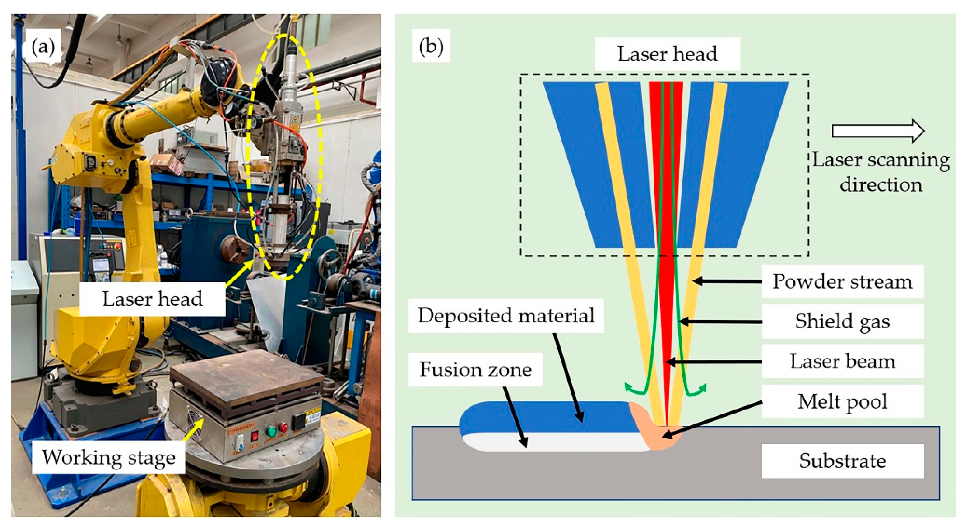
In the experiment, a high-power fiber laser with a beam wavelength of 1070–1080 nm (YLS-10000, IPG Photonics, Oxford, MA, USA), as shown in Figure 2, was employed for laser cladding. The diameter of the laser beam spot was 0.72 mm. Laser cladding coatings were fabricated on the substrate under the following parameters: 2.0 kW power, 2 mm/s laser scanning speed and 50 rpm powder feeding rate. High-purity argon with a flow rate of 5 L/min was used as shielding gas to prevent the oxidation of molten metals. Apart from that, argon was also used as a powder feeding gas with an 8 L/min flow rate. The offset distance of the laser track was 0.4 mm, hence, the overlap ratio for multi-track cladding was fixed at about 55%. The processing parameters used were optimized based on our preliminary research [24,25]. Substrates were placed on the working stage with heating function and then heated to 250 °C to release the internal stress before cladding.
After the cladding process, the specimens were cut along the direction transverse to the laser scanning direction with a size of 10 mm × 10 mm × 10 mm. Specimens for microstructure analysis were etched with an acid liquid (HF–HNO3–H2O = 1:4:5) after grinding and polishing. The microstructure of the coating was observed through an optical microscope (GX51, Olympus, Tokyo, Japan) and scanning electron microscope (SEM, Zeiss Gemini 300, Oberkochen, Germany). Meanwhile, energy-dispersive spectroscopy (EDS, OXFORD Xplore, Oxford, England) and X-ray diffraction (XRD, Bruker D8 ADVANCE, Karlsruhe, Germany) at a scanning speed of 10°/min (range 10° to 80°, Cu Kα radiation at 40 kV and 40 mA) were used to study the phase composition. Specimens for the electrochemical experiment were connected to a leading copper wire from the back side and sealed with epoxy resin, leaving an exposed working area of 1.0 cm2 (10 mm × 10 mm). Then, specimens were polished with emery paper (grade 1000–1500–2000), cleaned in deionized water, rinsed in ethanol and dried before electrochemical testing.

2.2. Electrochemical Measurements

As shown in Figure 3, an electrochemical workstation (Gamry Reference 600+, Gamry, Warminster, PA, USA) with a three-electrode system was employed to conduct the electrochemical experiments. All tests were proceeded in a 3.5 wt.% NaCl solution at room temperature. A saturated calomel electrode (SCE) was used as the reference electrode (RE), a platinum electrode was selected as the counter electrode (CE) and the specimen was the working electrode (WE). After 2 h immersion in the solution to reach a stable potential, the open-circuit potential (OCP) of the anodes was tested. The potentiodynamic polarization (PD) test was conducted in the range of −0.5 to 1.5 V (vs. OCP potential) with a voltage scanning speed of 0.1 mV/s. The electrochemical impedance spectra (EIS) of the specimens were also measured, with a frequency range from 100 kHz to 0.01 Hz at an amplitude of 5 mV, to evaluate the electrochemical behavior. The parameters for electrochemical tests were chosen according to ASTM standard G3-89 (2010) and ASTM G5-94 (2004), and in consideration of the capability of the Gamry electrochemical workstation on hand. To study the pitting process during the corrosion, the morphology of the cladding samples after corrosion was also observed with the above-mentioned SEM.

3. Results

3.1. Macroscopic Morphology of the Coating

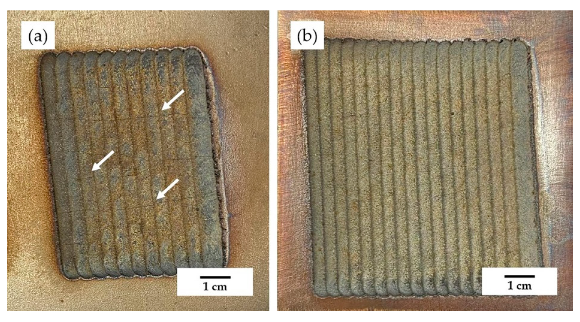
Figure 4 displays the surface topography of the coatings. The laser cladding tracks on the substrate are obvious and easy to recognize. Some cracks, marked with white arrows in Figure 4 and Figure 5, along the direction perpendicular to the laser scanning path were found on the surface of 55NiTi coating. The formation of these cracks was observed during the cooling stage after the cladding process, which is attributed to the release of the thermal stress caused by the rapid cooling [26]. However, no cracks were found on 55NiTi + 5Ni coating, the surface of which was plain and smooth. Figure 5 shows the cross-sectional morphologies of the coatings, and it can be seen that the cracks on the 55NiTi coating surface penetrated the whole cladding layer. However, both coatings formed the expected metallurgical bonding with the substrate. In addition, the fusion line between coating and substrate was more continuous and uniform in the 55NiTi + 5Ni coating. Studies have revealed that the phase transition temperature of NiTi alloy decreases with increasing content of Ni [22]. That is to say, the energy required for its phase transformation is reduced by increasing the content of Ni. With the same amount of heat input, while the coatings were fabricated under the same parameter settings, the phase transformation taking place in the 55NiTi + 5Ni coating would be more sufficient and close to thermodynamic equilibrium, which is beneficial to form a steady and uniform microstructure. As a result, the transition zone in the 55NiTi + 5Ni coating was also wider than that in the 55NiTi coating.

3.2. Phase Composition and Microstructure of the Coating

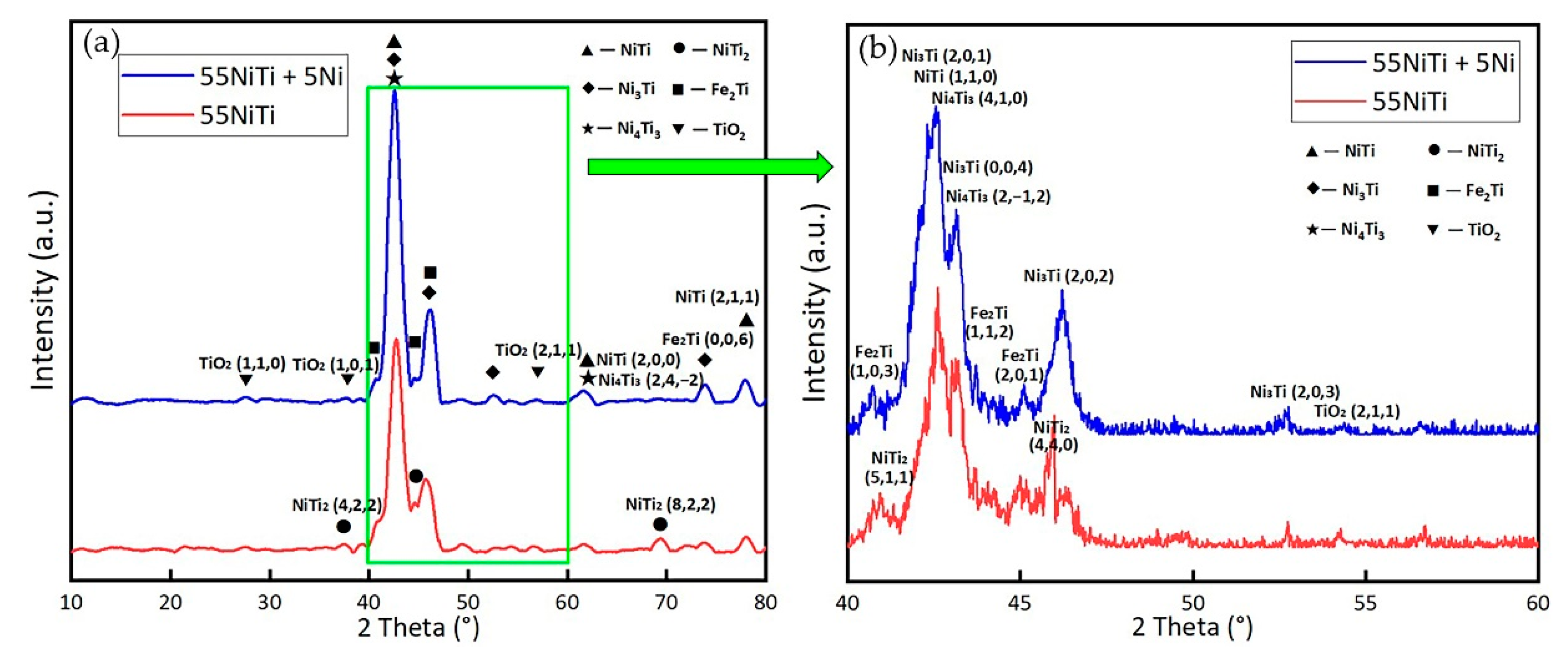
The XRD patterns of the laser cladding coatings are shown in Figure 6. It can be seen that the coatings were mainly composed of NiTi and Ni3Ti phases, which had the strongest diffraction peaks. There were also secondary phases such as Ni4Ti3, NiTi2 and Fe2Ti. It is well known that laser cladding is a quick melting and rapid nonequilibrium solidification process; therefore, multiple phases coexist and some diffraction peaks may overlap each other, even diverging from the equilibrium positions in the cladding layer [27]. For instance, Ni4Ti3 is a metastable phase with rhombohedral crystal structure precipitated from NiTi phase during the rapid cooling process [22,28], and its diffraction peaks were almost overlapped with that of the NiTi phase. This nanoscale structure is supposed to be decomposed to the stable Ni3Ti phase through the precipitation sequence Ni4Ti3 → Ni3Ti2 → Ni3Ti during the cooling process [23]. The formation of Fe2Ti results from the elemental Fe which is diluted from the substrate into the coating during the melting stage; hence, we believe that the Fe2Ti phase mainly existed in the bottom area of the coating. A previous study mentioned that the addition of Ni could suppress the formation of the brittle Fe2Ti phase [29]. The NiTi2 phase was only detected in the 55NiTi coating, while a Ti-rich environment is the precondition for the formation of a NiTi2 phase [21]. With the addition of Ni, even if there was a small amount of NiTi2 formed in the 55NiTi + 5Ni coating during early phases, it would react with surplus Ni atoms and transform to NiTi or Ni3Ti phase in the end. In addition, TiO2 was observed in both coatings, and is expected to be in the upper area of the coating. When the laser beam is removed, the high-temperature coating surface is directly exposed to the air, and titanium is an element with high chemical activity, which is favorable for the formation of titanium oxide.
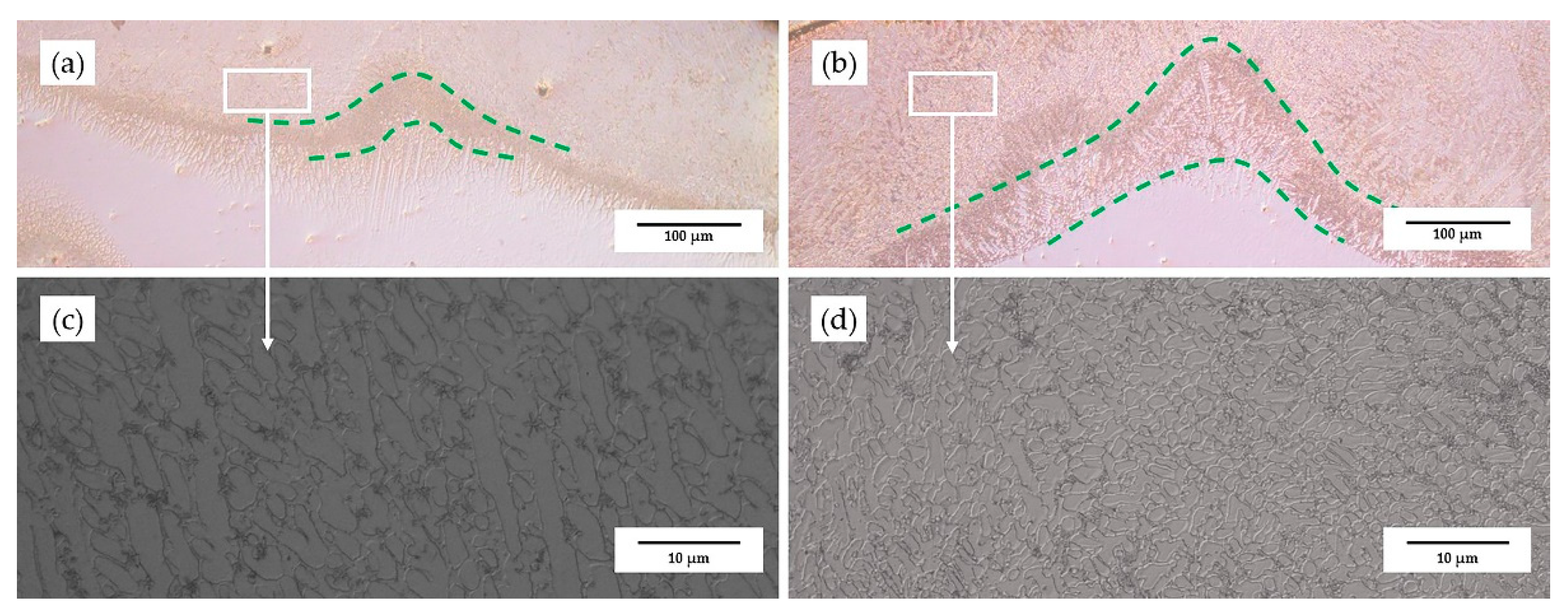
Figure 7 displays the transition area of the coatings, which is the boundary to the substrate. It can be seen that the width of the transition area of the 55NiTi + 5Ni coating was wider than that of the 55NiTi coating, which could be attributed the slight decrease of the transformation temperature caused by Ni addition. This is supported by reports that the phase transformation temperature of NiTi alloy decreases with the increasing content of Ni [22]. Comparing Figure 7c,d, it can be found that the microstructure of the 55NiTi + 5Ni coating was much denser than that of the 55NiTi coating due to the smaller grain size. It is well known that the solidification process starts from the bottom area of the coating and then moves upwards. With the addition of extra Ni particles, there are more embryos in the 55NiTi + 5Ni coating during the nucleation process—that is to say, the energy allocated to each grain for growth is not sufficient. Figure 8 shows the distribution of the dendrite grain size in the coating; the grain size was measured with the software Image-Pro Plus 6.0. The average grain size in the bottom area in the 55NiTi + 5Ni coating was only 3.1 μm, which is less than half that in the 55NiTi coating. The measured results are in line with the microstructure observed in Figure 7. With the increase of the undercooling degree, the critical nucleation radius decreased while the nucleation ratio increased, which resulted in the finer grain size in the cladding layer during the solidification process [26]. As is well known, small grains are beneficial to improve the mechanical properties of materials according to the fine-grain strengthening effect.
Figure 9 exhibits the microstructure of the upper area of the coating, as upper areas are close to the working surface, and have a significant impact on the coating performance. The average grain size was between 16 and 18 μm; the 55NiTi + 5Ni coating had slightly smaller dendrites than the 55NiTi coating. In addition to the dendrites’ and inter-dendrites’ structure, there a handful of black particles were also found in the boundary of the dendrites. EDS was used to identify the chemical composition of these phases, and the results of the spectra scan for the marked positions are listed in Table 3. Based on the data of position 1 and position 4 marked in Figure 9, their atomic ratio of Ni and Ti was close to 1:1, respectively, and it can be concluded that the dendrite structure was NiTi phase. Position 2 and position 5 were rich in Ni, with Ni–Ti atomic ratio of almost 3:1; therefore, the inter-dendrite phase can be identified as Ni3Ti phase. The black particles in position 3 and position 6 were dominant in O and Ti; combined with the XRD patterns, this suggests that they are TiO2 phase. Fe and Cr atoms, which diffused from the substrate, were on the one hand trapped in the NiTi phase and existed in the form of a solid solution due to the high cooling rate of the laser cladding process; on the other hand, Fe and Cr atoms have similar radius and electronegativity to Ni atom, and could partially replace the Ni atoms in the B2 structure [30].

3.3. Electrochemical Behavior of the Coating

3.3.1. Open-Circuit Potential (OCP) Analysis

The open-circuit potential (OCP) of the coatings in 3.5% NaCl solution for 2 h was measured, and the changes of the OCP with time are shown in Figure 10. OCP represents the corrosion tendency of a material; a more positive OCP indicates a surface with lower electrochemical activity [31]. The results show that the OCP value increased slowly at the beginning of the immersion but tended to become stable after 60 min due to the equilibrium of the passive film formation and its dilution [32]. The stabilized OCP values of the specimens are listed in Table 4. The OCP of the 55NiTi + 5Ni coating was about 0.13 V lower than that of the 55NiTi coating, which means the electrochemical activity of the 55NiTi + 5Ni coating was weaker.

3.3.2. Potentiodynamic Polarization Measurement

The potentiodynamic polarization measurement was done after the specimens were immersed in a 3.5% NaCl solution for 2 h (i.e., until their OCPs were stable. Figure 11 displays the potentiodynamic polarization results, which show an obvious passivation region for all three curves, indicating that a passive film was formed to protect the surface from corrosion. The corresponding corrosion potential (Ecorr), corrosion current density (Icorr) and corrosion rate calculated via Tafel fitting are summarized in Table 5. The corrosion potential for substrate 316L was the highest, at approximately 0.17 V, while those of 55NiTi + 5Ni and 55NiTi coatings were −0.50 and −0.61 V, respectively. It is clear that the formation of the passive film on the stainless-steel surface was mainly due to chromium (Cr), which has a lower standard electrode potential compared with iron and forms a chromium oxide film to separate the substrate from corrosive solution. However, for Ni–Ti based alloys, the excellent corrosion resistance is owing to titanium (Ti), whose standard electrode potential (−1.63 V) is even lower than chromium (−0.74 V), and the formed TiO2 film has a strong self-healing ability; once the present oxide film is corroded in the solution, a new TiO2 film will be formed to cover the pitting holes [33,34,35]. Therefore, the corrosion current densities and corrosion rates of both coatings were much lower than those of the substrate, which is attributed to the strong passivation ability of TiO2 passive film [34].
Surface morphologies of the specimens after the potentiodynamic polarization tests are displayed in Figure 12. It is obviously that substrate 316L was the most seriously corroded; the diameter of the pitting holes was over 100 μm. In contrast, the average size of the pitting holes on the coatings was less than 20 μm, which represents a significant improvement in corrosion resistance compared with the substrate. However, as reported in the literature, NiTi compounds can undergo local corrosion in chloride media [36,37].
Comparing the corrosion performance of the two coatings, both exhibited passivation ability, while the pitting potential of the 55NiTi + 5Ni coating was about 0.11 V nobler than that of the 55NiTi coating, and the corrosion current density and corrosion rate of the 55NiTi coating were two times larger than those of the 55NiTi + 5Ni coating; this is in agreement with the larger size of the pitting holes on the coating. In addition, the two obvious stages marked in the potentiodynamic curve of the 55NiTi + 5Ni coating shown in Figure 11 also indicate a stronger self-healing ability and better passivation property. Therefore, it can be speculated that, with the addition of extra Ni, the 55NiTi + 5Ni coating had a superior corrosion resistance to the 55NiTi coating.

3.3.3. EIS Analysis

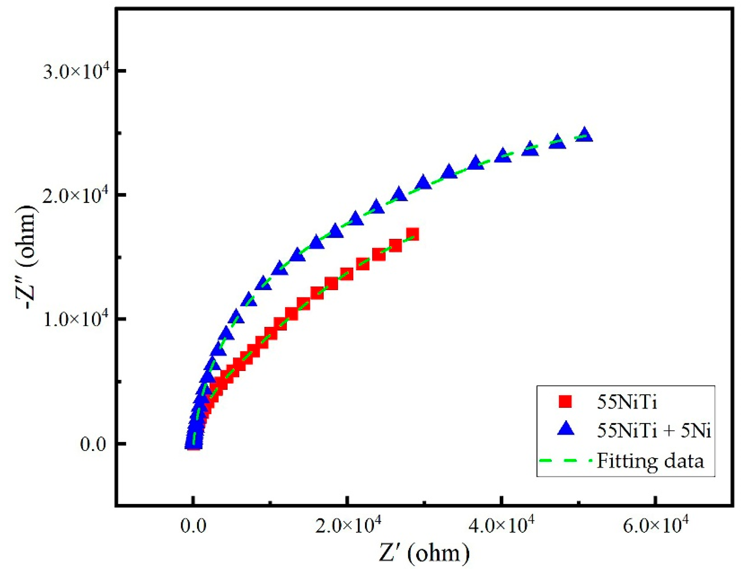
To further analyze the influence of the Ni addition on the corrosion resistance of NiTi coatings, electrochemical impedance spectroscopy (EIS) experiments were conducted in 3.5 wt.% NaCl solution. The Nyquist plots are shown in Figure 13, which are unfinished capacitance arcs. A bigger diameter of the capacitance arc represents a better coating corrosion resistance, while the Nyquist plots also show the charge transfer resistance in the formed passive film [38]. The results are consistent with the corrosion morphology shown in Figure 12, as fewer pitting holes were found in the 55NiTi + 5Ni coating, which is unfavorable for charge transfer.
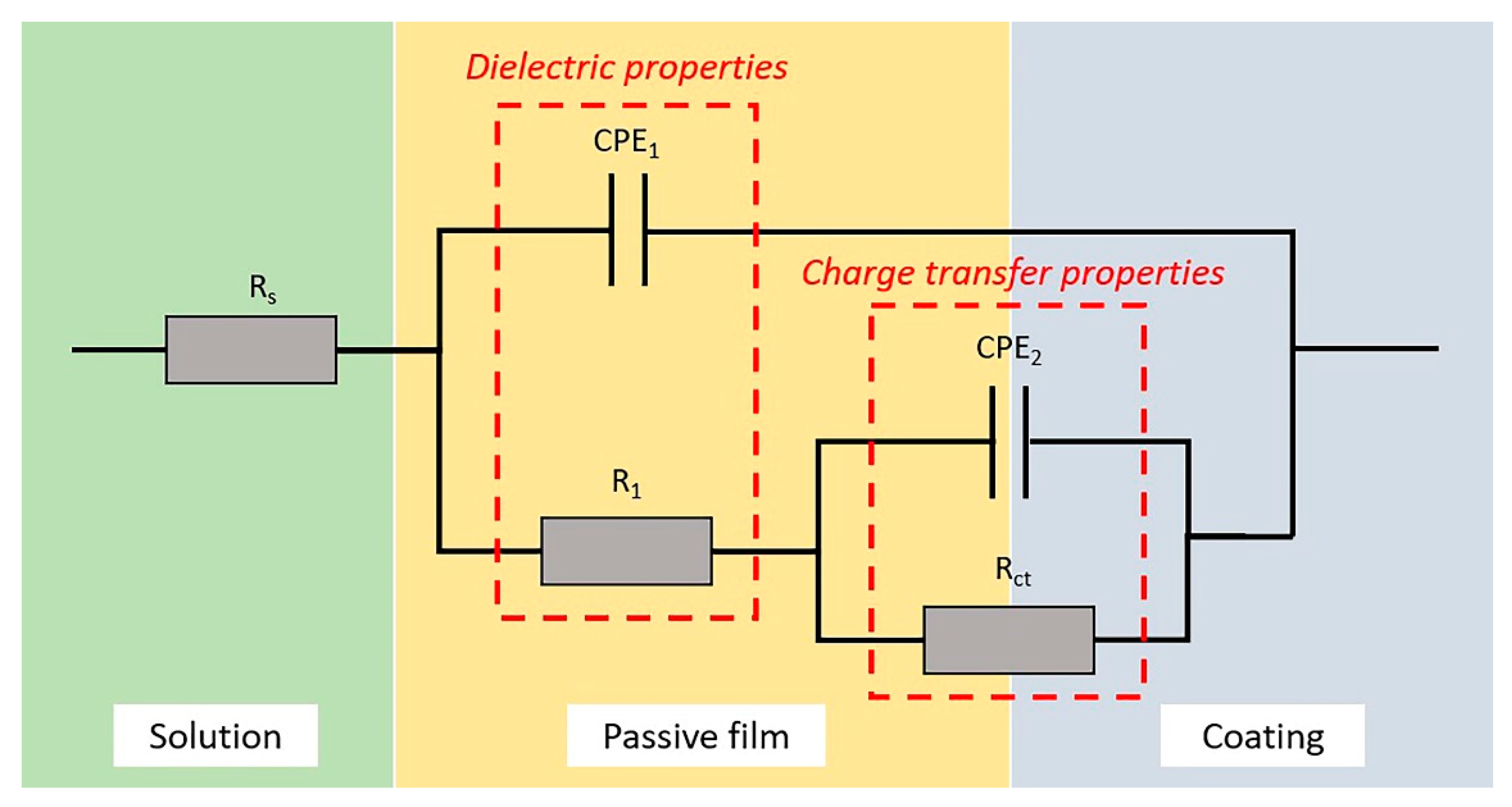
EIS spectra are usually analyzed with simulation data using a suitable equivalent circuit model. Figure 14 exhibits an equivalent electric circuit (EEC), which is proposed for a deeper analysis of the coatings’ electrochemical performance [25,31,39]. In the equivalent circuit, Rs represents the 3.5 wt.% NaCl solution resistance, R1 represents the resistance of the passive film parallel to its constant phase element (CPE1), Rct represents the charge transfer resistance in parallel with the capacitor CPE2, describing the double-layer charging–discharging structure. One study showed that R1 indicates the stability of the passive film and Rct denotes the charge transfer resistance, which means larger R1 and Rct indicate better coating corrosion resistance [40]. CPE is used to replace the capacitor in the circuit to compensate the influence of the surface uniformity of the coatings [41]. The impedance of the CPE is expressed by the formula below:
Z CPE = 1 Z 0 ( j ω ) n
where ω is the angular frequency (1 rad/s) defined as ω = 2πf, f is the frequency in Hz, j is the imaginary number, Z0 is the impedance constant and n (−1 ≤ n ≤ 1) is the experiential exponent of the CPE, which depends on the surface roughness and the distribution of the corrosion current density [42]. Usually, a larger value of n means a denser passive film and more uniform current density of the electrode surface. The equivalent components in the EEC were calculated with Gamry Echem Analyst software, and the corresponding fitting values are listed in Table 6. Results show that the values of R1, Rct and n of the 55NiTi + 5Ni coating were all better than those of the 55NiTi coating, indicating an observable improvement of the corrosion resistance due to the addition of Ni. This result is in consistent with the potentiodynamic polarization test as well. In addition, it can be seen in Figure 13 that the greened dash line, which is the fitting value according to the chosen equivalent circuit, is in good agreement with the experimental results, illustrating that the applied equivalent circuit was able to interpret the electrochemical behavior of the coating and passive film.

4. Discussion

4.1. The Impact of the Coating Microstructure and Composition on Corrosion Resistance

Coatings are used to improve the substrate corrosion resistance due to their capability to make the surface inactive or less reactive, usually by forming an oxide film mitigating the corrosion reactions. The outstanding corrosion resistance of NiTi coatings results from the formation of stable and continuous passive films, mainly consisting of titanium dioxide (TiO2). According to the previous research from Gaberšček et al. [43], the passive film preferentially grows at active sites such as grain boundaries, dislocations and inclusions. When the energy of the active site exceeds a critical value, the active site will become a nucleation site, where a passive film preferentially starts to form. Passive films can nucleate continuously at these sites and spread to connect with each other until they cover the whole metal surface.
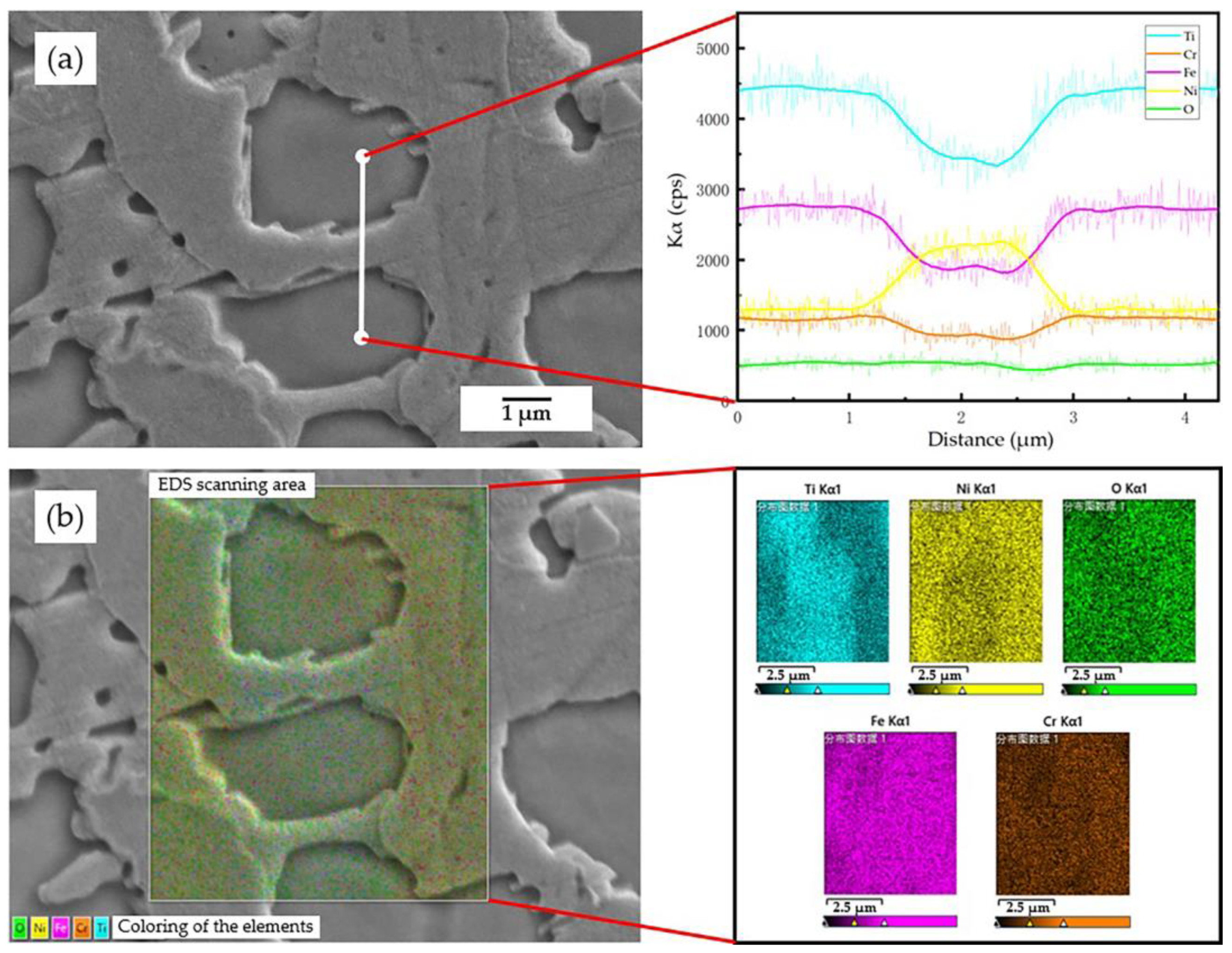
The formation of titanium oxide is influenced by the composition distribution and microstructure of the dendrites and inter-dendric areas in the coating. Figure 15 shows the EDS results of the dendrites and inter-dendritic areas in this study. The dendrites were primarily solidified and the inter-dendritic areas were posteriorly solidified. There was more Ti, Fe and Cr; and less Ni in the inter-dendritic areas. As a result, the passive film was first initiated in the inter-dendritic areas due to the Ti-rich environment, which reacts with O ions as a nucleation site. Comparing the two coatings, the addition of Ni could suppress the formation of Fe2Ti phase during the cooling process, which released more Ti atoms for the formation of a titanium oxide film afterwards [44]. Otherwise, too many precipitates would consume the Ti atom in the coating, resulting in the depletion of Ti and Cr, which is detrimental to the formation of a passive film. In addition, excessively solidified Fe and Cr may cause stacking faults and dislocations, which could offer more nucleation sites and is helpful for the formation of a dense passive film [38].
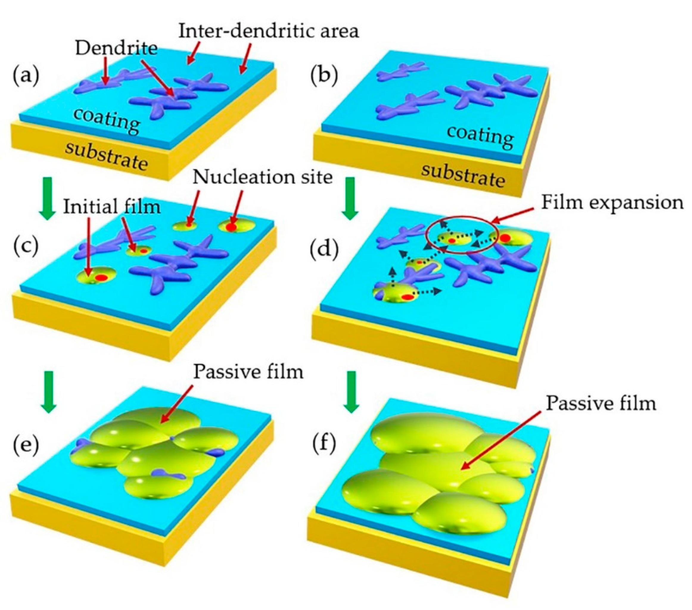
The above analysis reveals that Ni addition could promote the formation of uniform and dense dendrites in the cladding layer. In Figure 7 it can be clearly seen that the microstructure of the 55NiTi + 5Ni coating was much more compact and denser than that of the 55NiTi coating—that is to say, the distance between the neighboring inter-dendritic areas was also very close. Figure 16 displays the schematic illustration of the passive film initiation and expansion process on the coating surface. When the initial films form at the nucleation sites in the inter-dendritic area, they can quickly start to spread in all directions, reaching and connecting with each other until they cover the entire surface. It was observed that the dendrite size in the 55NiTi + 5Ni coating was much smaller than that of the 55NiTi coating due to the addition of Ni (Figure 8). A smaller grain size represents more grain boundaries, and grain boundaries play a role as active sites, which are favorable for the nucleation of passive films; therefore, a smaller grain size is also beneficial for generating a thin passivation film. In conclusion, with the addition of Ni, the passive film formed on the 55NiTi + 5Ni coating was much more homogeneous and thicker than that on the 55NiTi coating.

4.2. Corrosion Initiation and Expansion Process

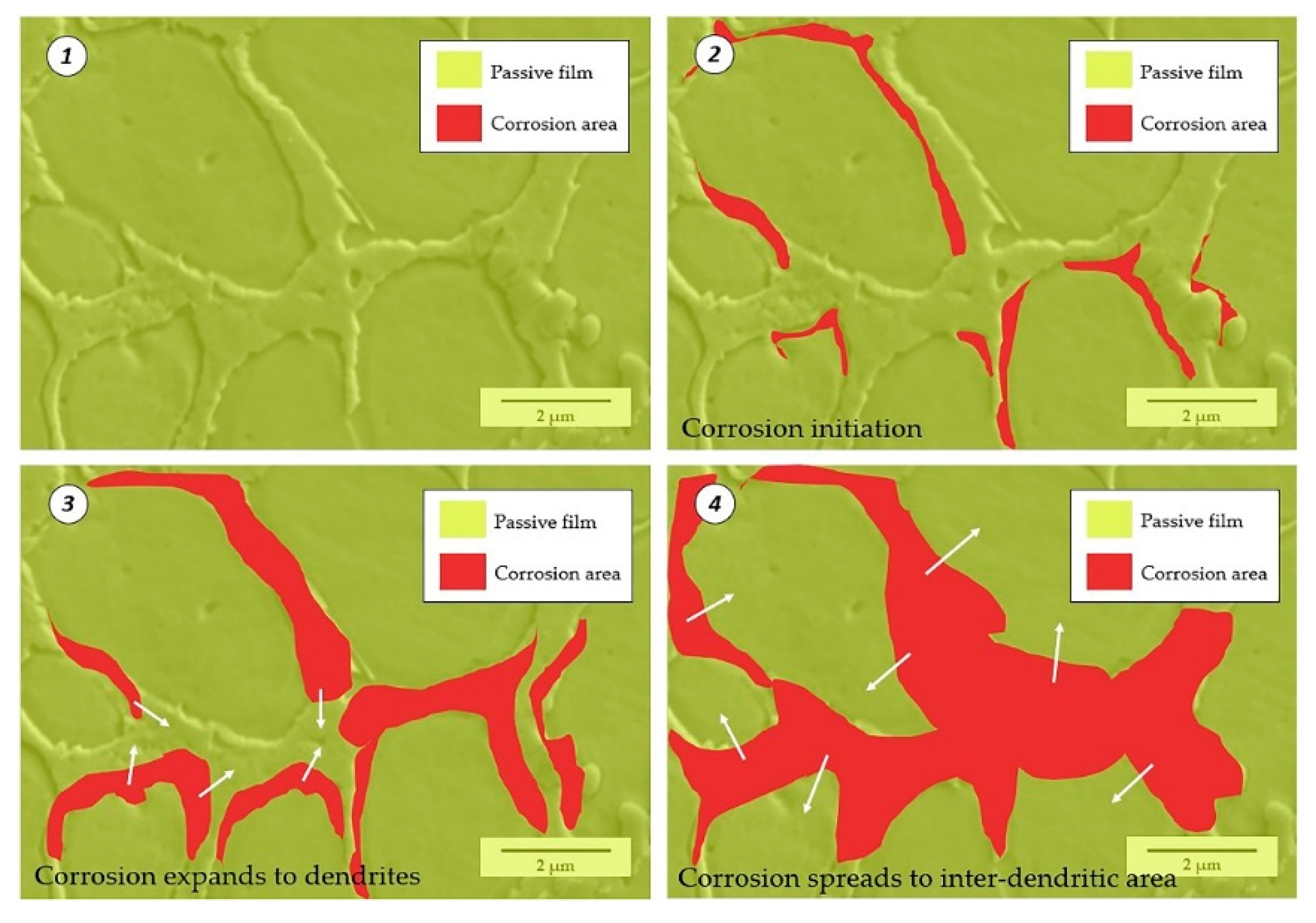
It is well known that the occurrence of corrosion is accompanied by the breakdown of the passive film, and usually, the corrosion preferentially occurs at secondary phase precipitates, grain boundaries, inclusions or other heterogeneities and processing defects such as pores and cracks [38]. The presence of these heterogeneities and defect areas hinders the formation of a homogeneous and dense passive layer. For instance, as shown in Figure 16e, areas where the passive film is absent or where the passive film is extremely thin, consequently lead to the formation of preferential sites for corrosion. During the pitting initiation process, the destroyed passive film is partially recovered due to the strong repassivation ability of TiO2. However, with the increasing pitting potential, once the equilibrium is broken, the pitting area will expand rapidly.
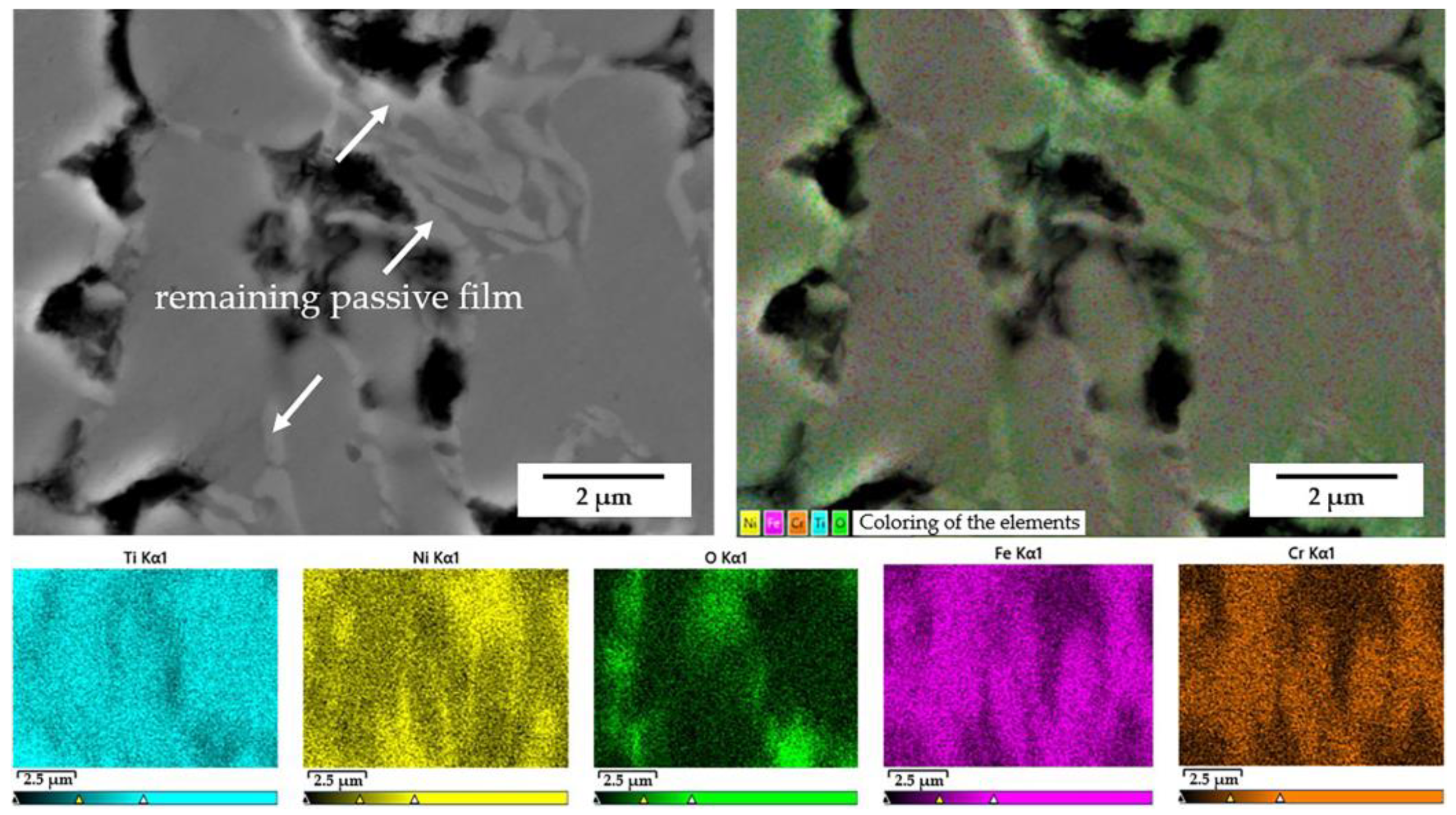
Figure 17 shows the EDS regional scanning results for the corrosion morphology of the 55NiTi coating. It is clear that the Ti-rich inter-dendritic area was more or less retained after corrosion. It is also worth noting the bright gray area on the surface of the retained inter-dendritic structure, which was proved to have a high oxygen content based on the EDS results. This area is supposed to be the remaining passive film, which contains titanium oxide. Figure 18 demonstrates an example where the corrosion initiated at the crack area of the coating surface. It can be seen that the corrosion began at the junction of the dendrites and inter-dendritic areas, then the dendrites was eroded preferentially while the inter-dendritic regions remained. As discussed above, Ti content is a key factor that affects the corrosion resistance. There was more titanium in the inter-dendritic region than in the dendrites. A higher titanium content will improve the electrochemical potential, and the potential differences will lead to the preferential erosion of the dendrites.
Figure 19 is a schematic illustration of the corrosion expansion process. It can be seen that the initiation and development of the corrosion in the coating is selective. Firstly, the junctions of dendrites and inter-dendritic areas are easily corroded, then the pitting area expands to the dendrites and finally spreads to cover the inter-dendritic areas.

4.3. The Impact of Immersion Duration on Corrosion Resistance of the Coating

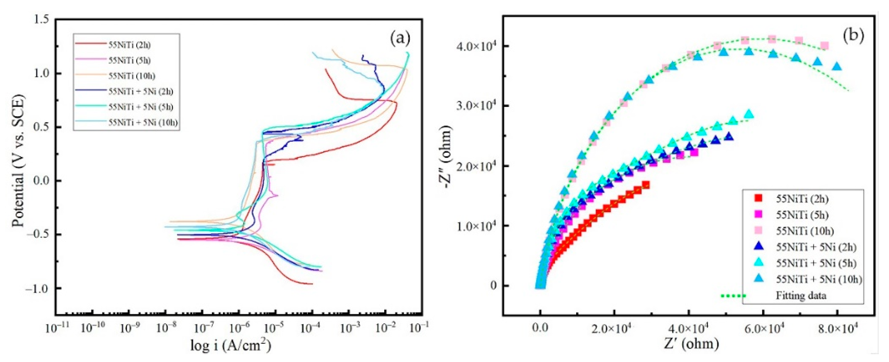
The samples were immersed in a 3.5 wt.% NaCl solution for 2, 5, and 10 h to study the effect of immersion duration on the coating corrosion resistance. Figure 20a exhibits the potentiodynamic polarization results of the coatings; the corrosion potential became higher with a longer immersion time in the solution, indicating that the corrosion tendency decreased. It is believed that the passive film on the coating surface would gradually become thicker within a certain time range until the equilibrium was broken. Figure 20b is the Nyquist diagram resulting from the electrochemical impedance spectroscopy (EIS) experiments. The diameter of the capacitance arc increased with as immersion time increased, which means the charge transfer resistance was also increasing. The results reveal that the corrosion resistance of the coatings improved with longer immersion time (10 h > 5 h > 2 h).

5. Conclusions

This paper investigated the effect of Ni addition on the microstructure and corrosion resistance of NiTi coatings prepared by laser cladding. The relationship between microstructure and corrosion resistance, the mechanism of the passive film formation and the corrosion initiation and expansion process were discussed in detail. The following conclusions can be drawn:
(1)
With the addition of Ni, the microstructure of the coatings became finer and denser; in the bottom area, the average grain size of the 55NiTi + 5Ni coating was less than half the grain size of the 55NiTi coating.
(2)
The results of electrochemical experiments show that the 55NiTi + 5Ni coating had a nobler corrosion potential and smaller corrosion current density, which was due to the homogeneous and thick passive film formed on the surface of the 55NiTi + 5Ni coating.
(3)
The initiation of the corrosion was selective. It initiated preferentially at the junctions of dendrites and inter-dendritic areas, then spread to the dendrites and finally covered the inter-dendritic areas.

Author Contributions

Conceptualization, Z.H.; methodology, Z.H. and Y.F.; validation, Y.F. and Z.D.; investigation, Y.F. and Z.D.; resources, Z.H.; data curation, Y.F. and Z.D; writing—original draft preparation, Y.F.; writing—review and editing, Z.H. and Y.F.; supervision, Z.H.; funding acquisition, Z.H. All authors have read and agreed to the published version of the manuscript.

Funding

This research was funded by the National Natural Science Foundation of China (51971163).

Institutional Review Board Statement

Not applicable.

Informed Consent Statement

Not applicable.

Data Availability Statement

Not applicable.

Acknowledgments

Author Feng, Yuqiang would like to thank Zhu, Chengnan and Feng, Yulei from Shanghai Jiao Tong University for the support of cladding samples preparation.

Conflicts of Interest

The authors declare no conflict of interest.

References

  1. Otsuka, K.; Ren, X. Physical metallurgy of Ti–Ni-based shape memory alloys. Prog. Mater. Sci. 2005, 50, 511–678. [Google Scholar] [CrossRef]
  2. Buehler, W.J.; Gilfrich, J.V.; Wiley, R.C. Effect of Low–Temperature Phase Changes on the Mechanical Properties of Alloys near Composition TiNi. J. Appl. Phys. 1963, 34, 1475–1477. [Google Scholar] [CrossRef]
  3. Tobushi, H.; Ikai, A.; Yamada, S.; Tanaka, K.; Lexcellent, C. Thermomechanical properties of TiNi shape memory alloy. J. Phys. IV. 1996, 6, 385–393. [Google Scholar] [CrossRef]
  4. Jackson, C.; Wagner, H.; Wasilewski, R. 55-Nitinol-The Alloy with a Memory: It’s Physical Metallurgy Properties, and Applications; NASA: Washington, DC, USA, January 1972; p. 5110.
  5. Yoneyama, T.; Miyazaki, S. Shape Memory Alloys for Biomedical Applications; Woodhead publishing limited: Cambridge, UK, 2009; p. 101. [Google Scholar]
  6. Khanlari, K.; Ramezani, M.; Kelly, P. 60NiTi: A Review of Recent Research Findings, Potential for Structural and Mechanical Applications, and Areas of Continued Investigations. Trans. Indian Inst. Met. 2017, 71, 781–799. [Google Scholar] [CrossRef]
  7. Saburi, T.; Yoshida, M.; Nenno, S. Deformation behavior of shape memory Ti–Ni alloy crystals. Scr. Metall. 1984, 18, 363–366. [Google Scholar] [CrossRef]
  8. Miyazaki, S.; Kimura, S.; Otsuka, K.; Suzuki, Y. The habit plane and transformation strains associated with the martensitic transformation in Ti-Ni single crystals. Scr. Metall. 1984, 18, 883–888. [Google Scholar] [CrossRef]
  9. Abd El-Fattah, H.A.; El-Mahallawi, I.; Shazly, M.H.; Khalifa, W.A. Microstructure Evolution of NiTi Magnetron Sputtered Thin Film on Different Substrates. Key Eng. Mater. 2020, 835, 68–74. [Google Scholar] [CrossRef]
  10. Samal, S.; Tyc, O.; Cizek, J.; Klecka, J.; Lukáč, F.; Molnárová, O.; de Prado, E.; Weiss, Z.; Kopeček, J.; Heller, L.; et al. Fabrication of Thermal Plasma Sprayed NiTi Coatings Possessing Functional Properties. Coatings 2021, 11, 610. [Google Scholar] [CrossRef]
  11. Pasang, T.; Tavlovich, B.; Yannay, O.; Jackson, B.; Fry, M.; Tao, Y.; Turangi, C.; Wang, J.C.; Jiang, C.P.; Sato, Y.; et al. Directionally-Dependent Mechanical Properties of Ti6Al4V Manufactured by Electron Beam Melting (EBM) and Selective Laser Melting (SLM). Materials 2021, 14, 603. [Google Scholar] [CrossRef]
  12. Vokoun, D.; Klimša, L.; Vetushka, A.; Duchoň, J.; Racek, J.; Drahokoupil, J.; Kopeček, J.; Yu, Y.-S.; Koothan, N.; Kei, C.-C. Al2O3 and Pt Atomic Layer Deposition for Surface Modification of NiTi Shape Memory Films. Coatings 2020, 10, 746. [Google Scholar] [CrossRef]
  13. Dai, J.; Liu, Z.; Yu, B.; Ruan, Q.; Chu, P.K. Effects of Ti, Ni, and Dual Ti/Ni Plasma Immersion Ion Implantation on the Corrosion and Wear Properties of Magnesium Alloy. Coatings 2020, 10, 313. [Google Scholar] [CrossRef] [Green Version]
  14. Verdian, M.; Raeissi, K.; Salehi, M. Corrosion performance of HVOF and APS thermally sprayed NiTi intermetallic coatings in 3.5% NaCl solution. Corros. Sci. 2010, 52, 1052–1059. [Google Scholar] [CrossRef]
  15. Zhong, M.; Liu, W. Laser surface cladding: The state of the art and challenges. Proc. Inst. Mech. Eng. Part C J. Mech. Eng. Sci. 2010, 224, 1041–1060. [Google Scholar] [CrossRef]
  16. Vilar, R. Laser cladding. J. Laser Appl. 1999, 11, 64–79. [Google Scholar] [CrossRef]
  17. Norhafzan, B.; Aqida, S.N.; Chikarakara, E.; Brabazon, D. Surface modification of AISI H13 tool steel by laser cladding with NiTi powder. Appl. Phys. A 2016, 122, 348. [Google Scholar] [CrossRef]
  18. Chiu, K.Y.; Cheng, F.T.; Man, H.C. Cavitation erosion resistance of AISI 316L stainless steel laser surface-modified with NiTi. Mater. Sci. Eng. A 2005, 392, 348–358. [Google Scholar] [CrossRef]
  19. Fu, B.; Feng, K.; Li, Z. Study on the effect of Cu addition on the microstructure and properties of NiTi alloy fabricated by laser cladding. Mater. Lett. 2018, 220, 148–151. [Google Scholar] [CrossRef]
  20. Lepule, M.L.; Obadele, B.A.; Andrews, A.; Olubambi, P.A. Corrosion and wear behaviour of ZrO2 modified NiTi coatings on AISI 316 stainless steel. Surf. Coat. Technol. 2015, 261, 21–27. [Google Scholar] [CrossRef]
  21. Okamoto, H.; Okamoto, H. Phase Diagrams for Binary Alloys; ASM International: Materials Park, OH, USA, 2000; Volume 44. [Google Scholar]
  22. Hornbuckle, B.C.; Xiao, X.Y.; Noebe, R.D.; Martens, R.; Weaver, M.L.; Thompson, G.B. Hardening behavior and phase decomposition in very Ni-rich Nitinol alloys. Mater. Sci. Eng. A 2015, 639, 336–344. [Google Scholar] [CrossRef]
  23. Khanlari, K.; Ramezani, M.; Kelly, P.; Cao, P.; Neitzert, T. Mechanical and microstructural characteristics of as-sintered and solutionized porous 60NiTi. Intermetallics 2018, 100, 32–43. [Google Scholar] [CrossRef]
  24. Feng, Y.; Du, Z.; Hu, Z. Study on the Effect of Ni Addition on the Microstructure and Properties of NiTi Alloy Coating on AISI 316 L Prepared by Laser Cladding. Materials 2021, 14, 4373. [Google Scholar] [CrossRef]
  25. Du, Z.; Hu, Z.; Feng, Y.; Mo, F. The Effect of Powder Composition on the Microstructure and Corrosion Resistance of Laser Cladding 60NiTi Alloy Coatings on SS 316L. Metals 2021, 11, 1104. [Google Scholar] [CrossRef]
  26. Zhou, S.; Xiong, Z.; Dai, X.; Liu, J.; Zhang, T.; Wang, C. Microstructure and oxidation resistance of cryomilled NiCrAlY coating by laser induction hybrid rapid cladding. Surf. Coat. Technol. 2014, 258, 943–949. [Google Scholar] [CrossRef]
  27. Zhuang, Q.; Zhang, P.; Li, M.; Yan, H.; Yu, Z.; Lu, Q. Microstructure, Wear Resistance and Oxidation Behavior of Ni-Ti-Si Coatings Fabricated on Ti6Al4V by Laser Cladding. Materials 2017, 10, 1248. [Google Scholar] [CrossRef] [Green Version]
  28. Carvalho, P.A.; Vilar, R. Laser alloying of zine with aluminum: Solidification structure. Surf. Coat. Technol. 1997, 91, 158–166. [Google Scholar] [CrossRef]
  29. Pouquet, J.; Miranda, R.M.; Quintino, L.; Williams, S. Dissimilar laser welding of NiTi to stainless steel. Int. J. Adv. Manuf. Technol. 2011, 61, 205–212. [Google Scholar] [CrossRef]
  30. Bozzolo, G.; Noebe, R.D.; Mosca, H.O. Site preference of ternary alloying additions to NiTi: Fe, Pt, Pd, Au, Al, Cu, Zr and Hf. J. Alloys Compd. 2005, 389, 80–94. [Google Scholar] [CrossRef] [Green Version]
  31. Hu, Y.; Wang, Z.; Ai, J.; Bu, S.; Liu, H. Preparation of Coating on the Titanium Surface by Micro-Arc Oxidation to Improve Corrosion Resistance. Coatings 2021, 11, 230. [Google Scholar] [CrossRef]
  32. Li, T.; Liu, L.; Zhang, B.; Li, Y.; Wang, F. An investigation on the continuous and uniform thin membrane passive film formed on sputtered nanocrystalline stainless steel. Corros. Sci. 2016, 104, 71–83. [Google Scholar] [CrossRef]
  33. Robin, A.; Meirelis, J.P. Influence of fluoride concentration and pH on corrosion behavior of titanium in artificial saliva. J. Appl. Electrochem. 2007, 37, 511–517. [Google Scholar] [CrossRef]
  34. Figueira, N.; Silva, T.M.; Carmezim, M.J.; Fernandes, J.C.S. Corrosion behaviour of NiTi alloy. Electrochim. Acta 2009, 54, 921–926. [Google Scholar] [CrossRef]
  35. Wever, D.J.; Veldhuizen, A.G.; Vries, J.d.; Busscher, H.J.; Uges, D.R.A.; Horn, J.R.v. Electrochemical and surface characterization of a nickel–titanium alloy. Biomaterials 1998, 19, 761–769. [Google Scholar] [CrossRef]
  36. Cheng, F.; Shi, P.; Man, H.C. A preliminary study of TiO2 deposition on NiTi by a hydrothermal method. Surf. Coat. Technol. 2004, 187, 26–32. [Google Scholar] [CrossRef]
  37. Cheng, Y.; Cai, W.; Li, H.; Zheng, Y. Surface modification of NiTi alloy with tantalum to improve its biocompatibility and radiopacity. J. Mater. Sci. 2006, 41, 4961–4964. [Google Scholar] [CrossRef]
  38. Shen, F.; Tao, W.; Li, L.; Zhou, Y.; Wang, W.; Wang, S. Effect of microstructure on the corrosion resistance of coatings by extreme high speed laser cladding. Appl. Surf. Sci. 2020, 517, 146085. [Google Scholar] [CrossRef]
  39. Shokouhfar, M.; Allahkaram, S.R. Effect of incorporation of nanoparticles with different composition on wear and corrosion behavior of ceramic coatings developed on pure titanium by micro arc oxidation. Surf. Coat. Technol. 2017, 309, 767–778. [Google Scholar] [CrossRef]
  40. Wang, Q.-Y.; Pei, R.; Liu, S.; Wang, S.-L.; Dong, L.-J.; Zhou, L.-J.; Xi, Y.-C.; Bai, S.-L. Microstructure and corrosion behavior of different clad zones in multi-track Ni-based laser-clad coating. Surf. Coat. Technol. 2020, 402, 126310. [Google Scholar] [CrossRef]
  41. Olaseinde, O.A. Comparative Study of the Effect of Temperature on the Corrosion Behaviour of 2205 Duplex Stainless Steel and 316 Austenitic Stainless Steel in Acidic Chloride Environment. Adv. Mater. Phys. Chem. 2015, 5, 185. [Google Scholar] [CrossRef] [Green Version]
  42. Stoynov, Z.; Grafov, B.; Savova-Stoynova, B.; Elkin, V. Electrochemical Impedance; Publishing House Science: Moscow, Russia, 1991. [Google Scholar]
  43. Gaberšček, M.; Pejovnik, S. Impedance spectroscopy as a technique for studying the spontaneous passivation of metals in electrolytes. Electrochim. Acta 1996, 41, 1137–1142. [Google Scholar] [CrossRef]
  44. Shi, Z.-P.; Wang, Z.-B.; Wang, J.-Q.; Qiao, Y.-X.; Chen, H.-N.; Xiong, T.-Y.; Zheng, Y.-G. Effect of Ni Interlayer on Cavitation Erosion Resistance of NiTi Cladding by Tungsten Inert Gas (TIG) Surfacing Process. Acta Metall. Sin. (Engl. Lett.) 2019, 33, 415–424. [Google Scholar] [CrossRef] [Green Version]
Figure 1. Morphologies of the powders: (a) single Ni powder; (b) 55NiTi alloy powder.
Coatings 11 01139 g001
Figure 2. IPG YLS-10000 laser equipment: (a) overview of the equipment; (b) schematic diagram of the laser cladding process.
Coatings 11 01139 g002
Figure 3. Electrochemical workstation: (a) Gamry Reference 600+; (b) schematic diagram of the three-electrode system.
Coatings 11 01139 g003
Figure 4. Surface topography of the coatings: (a) 55NiTi coating; (b) 55NiTi + 5Ni coating.
Coatings 11 01139 g004
Figure 5. Cross-sectional morphologies of the coatings: (a) 55NiTi coating; (b) 55NiTi + 5Ni coating.
Coatings 11 01139 g005
Figure 6. XRD results of the coatings: (a) overview of the patterns; (b) magnification of the patterns between 40° and 60°.
Coatings 11 01139 g006
Figure 7. Microstructure of the bottom area in the cladding layer: (a,c) 55NiTi coating; (b,d) 55NiTi + 5Ni coating.
Coatings 11 01139 g007
Figure 8. Distribution of the dendrite size in different areas of the coating.
Coatings 11 01139 g008
Figure 9. Microstructure of the upper area in the cladding layer: (a) 55NiTi coating; (b) 55NiTi + 5Ni coating.
Coatings 11 01139 g009
Figure 10. Open-circuit potential (OCP) curves of 2 h in 3.5 wt.% NaCl solution.
Coatings 11 01139 g010
Figure 11. Potentiodynamic polarization behavior of the coatings and substrate.
Coatings 11 01139 g011
Figure 12. Surface morphology of the samples after a 2 h potentiodynamic polarization test: (a) 55NiTi + 5Ni coating; (b) 55NiTi coating; (c) substrate stainless steel 316L.
Coatings 11 01139 g012
Figure 13. Nyquist plots from the electrochemical impedance spectroscopy (EIS) results of the coatings.
Coatings 11 01139 g013
Figure 14. Equivalent electric circuit of the coatings.
Coatings 11 01139 g014
Figure 15. Element distribution in the dendrites and inter-dendritic areas in the 55NiTi + 5Ni coating: (a) EDS line scanning results; (b) EDS region scanning results.
Coatings 11 01139 g015
Figure 16. Schematic illustration of the passive film initiation and expansion process: (a,c,e) 55NiTi coating; (b,d,f) 55NiTi + 5Ni coating.
Coatings 11 01139 g016
Figure 17. EDS regional scanning results for the 55NiTi coating after corrosion.
Coatings 11 01139 g017
Figure 18. Corrosion morphologies of the 55NiTi coating: (a) full view of the corrosion initiation at a crack area; (b) the middle of the corrosion area; (c) the edge of the corrosion area.
Coatings 11 01139 g018
Figure 19. Schematic illustration of the corrosion expansion process.
Coatings 11 01139 g019
Figure 20. Electrochemical behavior of the coatings under 2, 5 and 10 h immersion in a 3.5 wt.% NaCl solution: (a) PD polarization results; (b) Nyquist plots from EIS results.
Coatings 11 01139 g020
Table 1. Chemical composition of Ni and 55NiTi alloy powders (wt.%).
PowdersNiTiFeNbCoCSiO
Pure NiBal.0.0030.0200.0200.0030.006
55NiTi56.46Bal.0.0050.0100.0050.0050.037
Table 2. Chemical composition of AISI 316L stainless steel substrate (wt.%).
FeCrNiMoMnSiPCS
Bal.16.3210.122.040.920.340.0260.0160.015
Table 3. EDS results of spectra scan for the marked positions in Figure 9.
CoatingPositionNi (at.%)Ti (at.%)Fe (at.%)Cr (at.%)O (at.%)Major Phase
55NiTi131.4032.8317.2110.737.83NiTi
258.1227.459.404.120.91Ni3Ti
314.7224.5415.215.4140.12TiO2
55NiTi + 5Ni429.8430.1519.8612.407.75NiTi
561.8221.287.215.414.28Ni3Ti
616.9720.3116.467.4838.78TiO2
Table 4. The stable open-circuit potential of the substrate and coatings.
Sample55NiTi + 5Ni55NiTi316L
OCP (V)−0.495−0.3670.201
Table 5. Tafel fitting results of corrosion potential, corrosion current density and corrosion rate.
SampleEcorr (V)Icorr (μA/cm2)Corrosion Rate (mpy)
55NiTi + 5Ni−0.502.121.32
55NiTi−0.615.473.50
316L0.1760.8031.14
Table 6. Equivalent circuit parameters of the coatings.
CoatingsRs
(Ω·cm2)
R1
(Ω·cm2)
Rct
(Ω·cm2)
CPE1
−1·cm2·sn)
n1CPE2
−1·cm2·sn)
n2
55NiTi8.404.12 × 1042.14 × 1053.05 × 10−50.816.21 × 10−50.88
55NiTi + 5Ni10.827.53 × 1042.35 × 1055.70 × 10−50.974.86 × 10−50.96
Publisher’s Note: MDPI stays neutral with regard to jurisdictional claims in published maps and institutional affiliations.