
Enhancement of sp3 C Fraction in Diamond-like Carbon Coatings by Cryogenic Treatment


Abstract
:
1. Introduction
2. Materials and Methods
2.1. Substrate Treatment
2.2. DLC Deposition and Post-Treatment
2.3. Microstructure Characterization
2.4. Mechanical Performance Characterization
3. Results
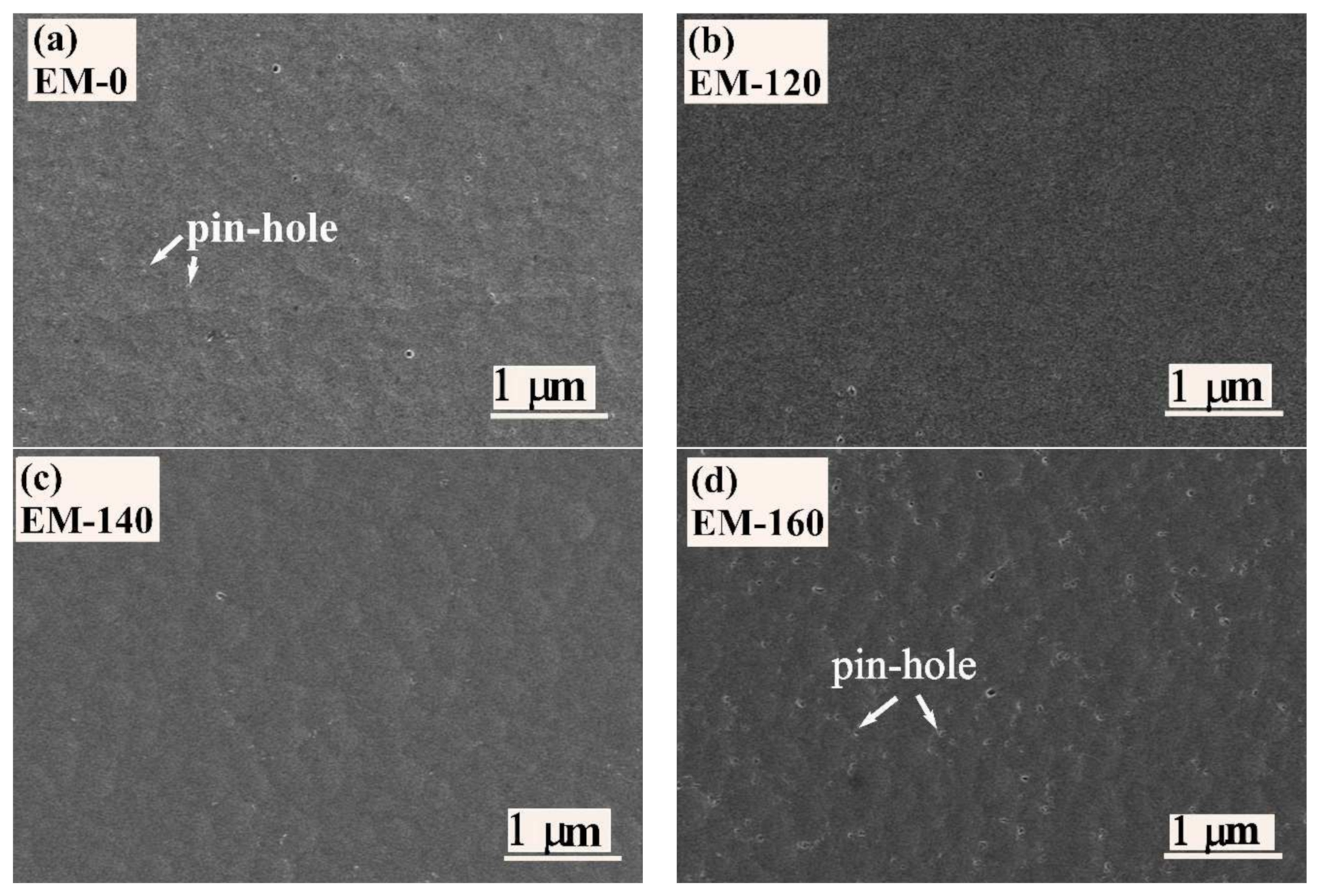
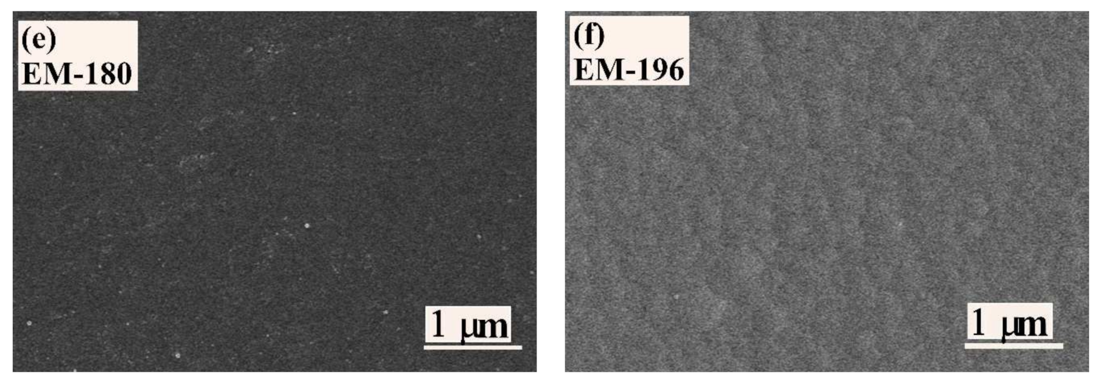
3.1. Microstructure
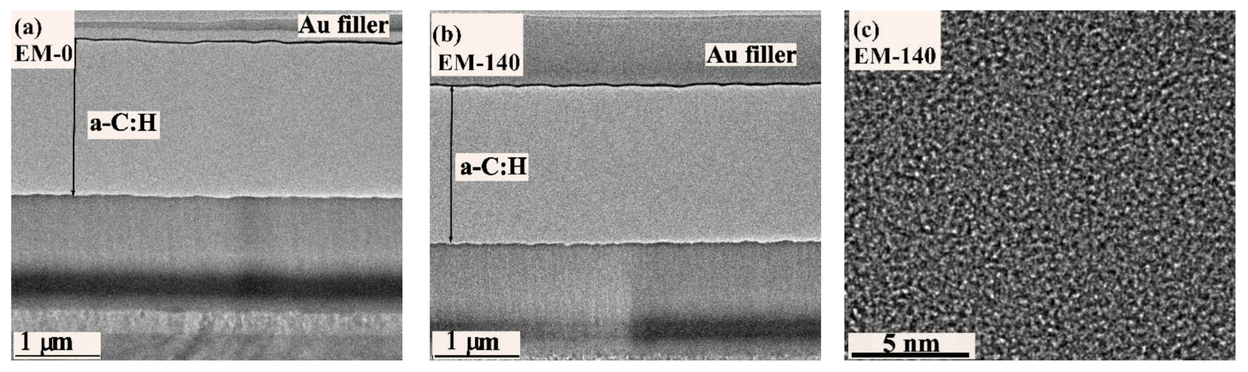
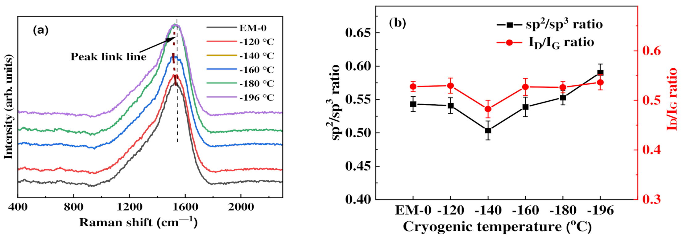
3.2. Chemical Bonding
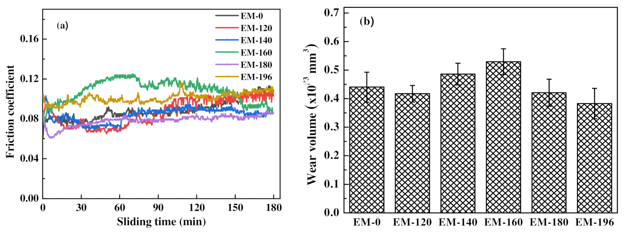
3.3. Mechanical Properties
4. Discussion
5. Conclusions
Author Contributions
Funding
Institutional Review Board Statement
Informed Consent Statement
Data Availability Statement
Acknowledgments
Conflicts of Interest
References
- Vetter, J. 60 years of DLC coatings: Historical highlights and technical review of cathodic arc processes to synthesize various DLC types, and their evolution for industrial applications. Surf. Coat. Technol. 2014, 257, 213–240. [Google Scholar] [CrossRef]
- Bewilogua, K.; Hofmann, D. History of diamond-like carbon films—From first experiments to worldwide applications. Surf. Coat. Technol. 2014, 242, 214–225. [Google Scholar] [CrossRef]
- Birney, R.; Cumming, A.; Campsie, P.; Gibson, D.; Hammond, G.; Hough, J.; Martin, I.; Reid, S.; Rowan, S.; Song, S.; et al. Coatings and surface treatments for enhanced performance suspensions for future gravitational wave detectors. Class. Quantum Grav. 2017, 34, 235012. [Google Scholar] [CrossRef] [Green Version]
- Saha, B.; Toh, W.; Liu, E.; Tor, S.; Hardt, D.; Lee, J. A review on the importance of surface coating of micro/nano-mold in micro/nano-molding processes. J. Micromech. Microeng. 2016, 26, 013002. [Google Scholar] [CrossRef] [Green Version]
- Markwitz, A.; Leveneur, J.; Gupta, P.; Suschke, K.; Futter, J.; Rondeau, M. Transition metal ion implantation into diamond-like carbon coatings: Development of a base material for gas sensing applications. J. Nanomater. 2015, 2015, 706417. [Google Scholar] [CrossRef] [Green Version]
- Son, M.; Zhang, T.; Jo, Y.; Kim, K. Enhanced electrochemical properties of the DLC films with an arc interlayer, nitrogen doping and annealing. Surf. Coat. Technol. 2017, 329, 77–85. [Google Scholar] [CrossRef]
- Fan, X.; Xue, Q.; Wang, L. Carbon-based solid-liquid lubricating coatings for space applications—A review. Friction 2015, 3, 191–207. [Google Scholar] [CrossRef] [Green Version]
- Yu, Q.; Chen, X.; Zhang, C.; Luo, J. Influence factors on mechanisms of superlubricity in DLC films: A Review. Front. Mech. Eng. 2020, 6, 65. [Google Scholar] [CrossRef]
- Nakaya, M.; Uedono, A.; Hotta, A. Recent progress in gas barrier thin film coatings on PET bottles in food and beverage applications. Coatings 2015, 5, 987–1001. [Google Scholar] [CrossRef] [Green Version]
- Voevodin, A.; Zabinski, J. Naocomposite and nanostructured tribological materials for space applications. Compos. Sci. Technol. 2005, 65, 741–748. [Google Scholar] [CrossRef]
- Robertson, J. Diamond amorphous carbon. Mater. Sci. Eng. 2002, 37R, 129–281. [Google Scholar] [CrossRef] [Green Version]
- Almeida, L.; Souza, A.; Costa, L.; Rangel, E.; Manfrinato, M.; Rossino, L. Effect of nitrogen in the properties of diamond-like carbon (DLC) coating on Ti6Al4V substrate. Mater. Res. Express 2020, 7, 065601. [Google Scholar] [CrossRef]
- Zhang, D.; Li, S.; Zuo, X.; Guo, P.; Ke, P.; Wang, A. Structural and mechanism study on enhanced thermal stability of hydrogenated diamond-like carbon films doped with Si/O. Diam. Relat. Mater. 2020, 108, 107923. [Google Scholar] [CrossRef]
- Peng, J.; Yang, M.; Zeng, J.; Su, D.; Liao, J.; Yick, M. Influence of nitrogen doping on the thermal stability of hydrogenated amorphous diamond coating. Thin Solid Films 2020, 709, 138188. [Google Scholar] [CrossRef]
- Wang, J.; Pu, J.; Zhang, G.; Wang, L. Architecture of superthick diamond-like carbon films with excellent high temperature wear resistance. Tribol. Int. 2015, 81, 129–138. [Google Scholar] [CrossRef]
- Braak, R.; May, U.; Onuseit, L.; Repphun, G.; Guenther, M.; Schmid, C.; Durst, K. Accelerated thermal degradation of DLC-coatings via growth defects. Surf. Coat. Technol. 2018, 349, 272–278. [Google Scholar] [CrossRef]
- Peng, J.; Yang, M.; Bi, J.; Sheng, R.; Li, L. Hydrogen existence state of a hydrogenated amorphous carbon coating and its thermal stability. Diam. Relat. Mater. 2019, 99, 107535. [Google Scholar] [CrossRef]
- Yamamoto, S.; Kawana, A.; Ichimura, H.; Masuda, C. Relationship between tribological properties and sp3/sp2 structure of nitrogenated diamond-like carbon deposited by plasma CVD. Surf. Coat. Technol. 2012, 210, 1–9. [Google Scholar] [CrossRef]
- Muguruma, T.; Iijima, M.; Kawaguchi, M.; Mizoguchi, I. Effects of sp2/sp3 ratio and hydrogen content on in vitro bending and frictional performance of DLC-coated orthodontic stainless steels. Coatings 2018, 8, 199. [Google Scholar] [CrossRef] [Green Version]
- Li, A.; Li, X.; Wang, Y.; Lu, Z.; Wang, Y.; Zhang, G.; Wu, Z. Investigation of mechanical and tribological properties of super-thick DLC films with different modulation ratios prepared by PECVD. Mater. Res. Express 2019, 6, 086433. [Google Scholar] [CrossRef]
- Takabayashi, S.; Okamoto, K.; Nakatani, T. Influence of post-annealing on a diamondlike carbon film analyzed by Raman spectroscopy. Surf. Interface Anal. 2018, 50, 441–447. [Google Scholar] [CrossRef]
- Grenadyorov, A.; Solovyev, A.; Oskomov, K.; Oskirko, V.; Semenov, V. Thermal stability of anti-reflective and protective a-C:H:SiOx coating for infrared optics. Appl. Surf. Sci. 2020, 510, 145433. [Google Scholar] [CrossRef]
- Peng, J.; Liao, J.; Yang, M.; Liao, J.; Bi, J. Effect of annealing treatment on the tribological performance of hydrogenated amorphous diamond coatings doped with nitrogen. Ceram. Intern. 2021, 47, 13423–13431. [Google Scholar] [CrossRef]
- Durandurdu, M. Formation of a very high-density amorphous phase of carbon and its crystallization into a simple cubic structure at high pressure. Comput. Mater. Sci. 2021, 200, 110822. [Google Scholar] [CrossRef]
- Tan, L.; Sheng, H.; Lou, H.; Cheng, B.; Xuan, Y.; Prakapenka, V.; Greenberg, E.; Zeng, Q.; Peng, F.; Zeng, Z. High-pressure tetrahedral amorphous carbon synthesized by compressing glassy carbon at room temperature. J. Phys. Chem. C 2020, 124, 5489–5494. [Google Scholar] [CrossRef]
- Edalati, K.; Horita, Z. Phase transformations during high-pressure torsion (HPT) in titanium, cobalt and graphite. IOP Conf. Ser.: Mater. Sci. Eng. 2014, 63, 012099. [Google Scholar] [CrossRef] [Green Version]
- Li, X.; Wang, A.; Lee, K. Insights on low-friction mechanism of amorphous carbon films from reactive molecular dynamics study. Tribol. Int. 2019, 131, 567–578. [Google Scholar] [CrossRef]
- Bai, Y.; Yu, Z.; Liu, R.; Li, N.; Yan, S.; Yang, K.; Liu, B.; Wei, D.; Wang, L. Pressure-induced crystallization and phase transformation of para-xylene. Sci. Rep. 2017, 7, 5321. [Google Scholar] [CrossRef] [Green Version]
- Manimunda, P.; Al-Azizi, A.; Kim, S.; Chromik, R. Shear-induced structural changes and origin of ultralow friction of hydrogenated diamond-like carbon (DLC) in dry environment. ACS Appl. Mater. 2017, 9, 16704–16714. [Google Scholar] [CrossRef] [PubMed]
- Fukumasu, N.; Bernardes, C.; Ramirez, M.; Trava-Airoldi, V.; Souza, R.; Machado, I. Local transformation of amorphous hydrogenated carbon coating induced by high contact pressure. Tribol. Int. 2018, 124, 200–208. [Google Scholar] [CrossRef]
- Chen, L.; Liu, K.; Wei, X.; Lu, Z.; Ren, N.; Zhang, G.; Xue, Q. Enhancement in the tribological properties of Cr/DLC multilayers in methane: Structural transformation induced by sliding. SN Appl. Sci. 2019, 1, 1483. [Google Scholar] [CrossRef] [Green Version]
- Kalinichenko, A.; Perepelkin, S.; Strel’nitskij, V. Dependence of intrinsic stress and structure of ta-C film on ion energy and substrate temperature in model of the non-local thermoelastic peak. Diam. Relat. Mater. 2010, 19, 996–998. [Google Scholar] [CrossRef]
- Esmeryan, K.; Castano, C.; Bressler, A.; Abolghasemibizaki, M.; Fergusson, C.; Roberts, A.; Mohammad, R. Kinetically driven graphite-like to diamond-like carbon transformation in low temperature laminar diffusion flames. Diam. Relat. Mater. 2017, 75, 58–68. [Google Scholar] [CrossRef]
- Liao, J.; Li, L.; Peng, J.; Gao, J. Effects of deep cryogenic treatment on the microstructure and friction performance of M35 high-speed steel. J. Phys. Conf. Ser. 2020, 1676, 012098. [Google Scholar] [CrossRef]
- Jovicevic-Klug, P.; Jenko, M.; Jovicevic-Klug, M.; Batic, B.; Kovac, J.; Podgornik, B. Effect of deep cryogenic treatment on surface chemistry and microstructure of selected high-speed steels. Appl. Surf. Sci. 2021, 548, 149257. [Google Scholar] [CrossRef]
- Dhokey, N.; Hake, A.; Kadu, S.; Bhoskar, I.; Dey, G. Influence of cryoprocessing on mechanism of carbide development in cobalt-bearing high-speed steel (M35). Metall. Mater. Trans. A 2014, 45, 1508–1516. [Google Scholar] [CrossRef]
- Gavriljuk, V.; Theisen, W.; Sirosh, V.; Polshin, E.; Kortmann, A.; Mogilny, G.; Petrov, Y.; Tarusin, Y. Low-temperature martensitic transformation in tool steels in relation to their deep cryogenic treatment. Acta Mater. 2013, 61, 1705–1715. [Google Scholar] [CrossRef]
- Kong, Y.; Chen, Q.; Wang, L. Microstructures and tribological properties of GLC coated 100Cr6 bearing steels. Mater. Res. Express 2017, 4, 116404. [Google Scholar] [CrossRef]
- Zhao, Y.; Nie, C.; Jin, Y.; Zhu, W.; Liu, X.; Nie, Y. Effect of cryogenic treatment on friction and wear property of DLC film/304 stainless steel. Adv. Mater. Res. 2014, 900, 767–772. [Google Scholar] [CrossRef]
- Wang, J.; Jia, Q.; Yuan, X.; Wang, S. Experimental study on friction and wear behaviour of amorphous carbon coatings for mechanical seals in cryogenic environment. Appl. Surf. Sci. 2012, 258, 9531–9535. [Google Scholar] [CrossRef]
- Aggleton, M.; Burton, J.; Taborek, P. Cryogenic vacuum tribology of diamond and diamond-like carbon films. J. Appl. Phys. 2009, 106, 013504. [Google Scholar] [CrossRef] [Green Version]
- Gradt, T.; Borner, H.; Schneider, T. Low temperature tribometers and the behaviour of ADLC coatings in cryogenic environment. Tribol. Intern. 2001, 34, 225–230. [Google Scholar] [CrossRef]
- Ostrovskaya, Y.; Strelnitskij, V.; Kuleba, V.; Gamulya, G. Friction and wear behaviour of hard and superhard coatings at cryogenic temperatures. Tribol. Intern. 2001, 34, 255–263. [Google Scholar] [CrossRef]
- Hu, A.; Alkhesho, I.; Duley, W.; Zhou, H. Cryogenic graphitization of submicrometer grains embedded in nanostructured tetrahedral amorphous carbon films. J. Appl. Phys. 2006, 100, 084319. [Google Scholar] [CrossRef]
- Knápek, A.; Sobola, D.; Burda, D.; Danhel, A.; Mousa, M.; Kolarík, V. Polymer graphite pencil lead as a cheap alternative for classic conductive SPM probes. Nanomaterials 2019, 9, 1756. [Google Scholar] [CrossRef] [Green Version]
- Tambe, N.; Bhushan, B. Nanoscale friction-induced phase transformation of diamond-like carbon. Scr. Mater. 2005, 52, 751–755. [Google Scholar] [CrossRef]
- Catena, A.; McJunkin, T.; Agnello, S.; Gelardi, F.; Wehner, S.; Fischer, C. Surface morphology and grain analysis of successively industrially grown amorphous hydrogenated carbon films (a-C:H) on silicon. Appl. Surf. Sci. 2015, 347, 657–667. [Google Scholar] [CrossRef]


| Group | Pre-Treat | DLC Coat | Post-Treat | |||
|---|---|---|---|---|---|---|
| Substrate | Quenching | Tempering | Cryo-Treat-I | Cryo-Treat-II | ||
| EM-0 | EM35 | YES | YES | YES | YES | NO |
| EM-T | EM35 | YES | YES | YES | YES | YES (at T) |
| Si-0 | Si wafer | NO | NO | NO | YES | NO |
| Si-T | Si wafer | NO | NO | NO | YES | YES (at T) |
| Item | Item Parameter |
|---|---|
| Substrate cleaning | Base pressure 5 × 10⁻³ Pa; voltage bias 200 V; Ar gas flow rate 250 sccm; duration 90 min |
| Cr + WC interlayer | Target power 5 kW; heating 150 °C; duration 50 min |
| a-C:H layer | Bias voltage 740 V; coil current 2 A; C2H2 gas flow rate 250 sccm; heating 300 °C; duration 80 min; work pressure 0.8–1 Pa |
Publisher’s Note: MDPI stays neutral with regard to jurisdictional claims in published maps and institutional affiliations. |
© 2021 by the authors. Licensee MDPI, Basel, Switzerland. This article is an open access article distributed under the terms and conditions of the Creative Commons Attribution (CC BY) license (https://creativecommons.org/licenses/by/4.0/).
Share and Cite
Peng, J.; Liao, J.; Peng, Y.; Xiao, Y.; Huang, J.; Li, L. Enhancement of sp3 C Fraction in Diamond-like Carbon Coatings by Cryogenic Treatment. Coatings 2022, 12, 42. https://doi.org/10.3390/coatings12010042
Peng J, Liao J, Peng Y, Xiao Y, Huang J, Li L. Enhancement of sp3 C Fraction in Diamond-like Carbon Coatings by Cryogenic Treatment. Coatings. 2022; 12(1):42. https://doi.org/10.3390/coatings12010042
Chicago/Turabian StylePeng, Jihua, Jingwen Liao, Yinglong Peng, Yang Xiao, Jinhai Huang, and Liejun Li. 2022. "Enhancement of sp3 C Fraction in Diamond-like Carbon Coatings by Cryogenic Treatment" Coatings 12, no. 1: 42. https://doi.org/10.3390/coatings12010042