Article

CNT-ZnO Core-Shell Photoanodes for Photoelectrochemical Water Splitting

by
Vasu Prasad Prasadam
,
Ali Margot Huerta Flores
,
Jean-Nicolas Audinot
and
Naoufal Bahlawane
*
Material Research and Technology Department, Luxembourg Institute of Science and Technology, Rue du Brill, Belvaux, L-4422 Luxembourg, Luxembourg
*
Author to whom correspondence should be addressed.
Coatings 2022, 12(1), 47; https://doi.org/10.3390/coatings12010047
Submission received: 1 December 2021 / Revised: 13 December 2021 / Accepted: 15 December 2021 / Published: 1 January 2022
(This article belongs to the Topic Inorganic Thin Film Materials)

Abstract

:
Solar-driven water splitting is a promising route toward clean H2 energy and the photoelectrochemical approach attracts a strong interest. The oxygen evolution reaction is widely accepted as the performance limiting stage in this technology, which emphasizes the need of innovative anode materials. Metal oxide semiconductors are relevant in this respect owing to their cost-effectiveness and broad availability. The combination of chemical vapor deposition and atomic layer deposition was implemented in this study for the synthesis of randomly oriented CNT-ZnO core-shell nanostructures forming an adhering porous coating. Relative to a directly coated ZnO on Si, the porous structure enables a high interface area with the electrolyte and a resulting 458% increase of the photocurrent density under simulated solar light irradiation. The photoelectrochemical characterization correlates this performance to the effective electrons withdrawing along the carbon nanotubes (CNTs), and the resulting decrease of the onset potential. In terms of durability, the CNT-ZnO core–shell structure features an enhanced photo-corrosion stability for 8 h under illumination and with a voltage bias.

Graphical Abstract

1. Introduction

Most carbon emissions are related to the combustion of fossil fuels for transportation and electricity generation, which results in the greenhouse effect with the worrying global warming [1]. A widespread implementation of renewable non-fossil fuels is therefore relevant in this context [2]. Hydrogen is a clean energy carrier with enormous potentials for transportation and power generation owing to its high energy density (142 MJ/kg) relative to gasoline (47 MJ/kg) [3,4]. A positive impact on the environment requires, however, a shift from the current dominance of H2 production from fossil fuels. Clean H2 production is feasible with solar water splitting technology e.g., photovoltaic coupled with electrolyser (PV-EC), photo catalysis (PC) and photo electrochemical catalysis (PEC) [5]. PEC presents advantageous scalability and cost among these technologies; nevertheless, the performance is limited by the availability of efficient photoanode materials that are responsible for the oxygen evolution reaction (OER) [6,7].
Conventional photovoltaic electrode materials with low band gap energy (1.3–2.4 eV) and high carrier mobility, e.g., transition metal sulphides and selenides, were successfully used in PEC technology. Nevertheless, these materials feature a strong ageing due to photo-corrosion in acidic and alkaline media [8,9,10]. Semiconductor metal oxide alternatives are less expensive, non-toxic and abundantly available in the earth’s crust. Several oxides have been studied intensively as photoanodes such as, BiVO4, TiO2, ZnO, WO3 and Fe2O3 [11,12]. Among these materials ZnO has a high charge mobility 200–300 cm2·V−1·s−1 and an electron lifetime exceeding 10 s [13], but it has a limited chemical stability [10]. ZnO features a favorable band alignment with a more negative conduction band (−0.15 VRHE) relative to water reduction potential (0 VRHE) and a more positive valence band (3.05 VRHE) relative to water oxidation potential (1.23 VRHE) [14]. VRHE stands for potentials in volts relative to the reversible hydrogen electrode (RHE). The resulting high band gap limits, however, the theoretical photocurrent to ~1.8 mA·cm−2 [8]. The enhancement of ZnO’s performance as a photoanode in PEC water splitting was reported via nano-structuring, doping and the implementation of a co-catalyst [15], but the chemical instability remains a primary issue in highly acidic and highly alkaline media [16]. The dark electrochemical dissolution of ZnO occurs at 2 VRHE [17]. The photo generated surface holes oxidize ZnO in aqueous solutions, which enhances its corrosion. The last might be inhibited by cationic/anionic doping, hybridization with co-catalysts, carbon materials or by forming heterojunctions [18]. The photo-corrosion of the anode material can be reduced in PEC by adding a hole scavenging agent in the electrolyte [19,20] or by implementing a passivation layer. In this context, TiO2 [21], CoO [22], CoNiOx [23], NiO [24] and Ta2O5 [25] confer a long-term photo stability to ZnO. Adjusting the thickness of the passivation layer is crucial to optimize the resulting performance [26], making atomic layer deposition (ALD) a particularly efficient process [27]. The implementation of solution-based processes requires the application of an additional hydroxide overlayer [28].
Photocurrent densities varying from 0.2 to 0.6 mA·cm−2 (at 1.23 VRHE) [21,29,30] were reported for ZnO nanostructures synthesised by wet chemistry, and the reproducibility is noticed as an issue. Chemical vapour deposition (CVD) resulted in a reproducible photocurrent of Iph = 1 mA·cm−2 (at 1.23 VRHE) [31,32]; however, the needed high deposition temperature is restrictive in terms of substrates. Covering ZnO surface with reduced graphene oxide [33,34] or C3N4 [35] confers a few hours of protection from photo-corrosion. The application of a carbon layer was also proven efficient for the limitation of the ZnO photo-corrosion in aqueous solutions [36], and this effect was attributed to the improved charge carrier separation [36]. In fact, the work function of ALD grown ZnO is 3.78 eV [37], while that of multiwall CNT (MWCNT) is reported at 4.95 eV [38]. A spontaneous electron transfer is therefore expected from ZnO to MWCNT, followed by the formation of a Schottky barrier, for which the height might be reduced via the application of a forward bias, resulting in the promotion of a further flow of electrons from ZnO to CNT [39]. The high electrical conductivity of carbon is an asset against the accumulation of electrons at the ZnO-carbon junction [40]. The CNT-ZnO heterostructures are so far synthesised by wet chemistry that requires the functionalization of CNT [41,42,43,44] to secure an efficient dispersion. This functionalization adversely affects the electrical properties of CNT [45]. Furthermore, the wet chemistry-based synthesis results in composite films where the individual CNTs are not directly attached to the substrates, which is unfavourable for the electron collection. These drawbacks can be addressed using hybrid CVD/ALD for the direct growth of CNTs on the target surface, and their consecutive conformal coverage with functional transition metal oxides [46].
Atomic layer deposition (ALD) and chemical vapor deposition are highly suitable for low temperature deposition of pinhole-free, conformal and crystalline TiO2 [31,47] on diverse nanostructures such as ZnO [31] and Si [47] nanowires. These advantages were used to design semiconductor-ZnO heterostructures with core–shell architectures featuring promising photoelectrochemical performances. In this context, we find i.e., CdS-ZnO (Iph = 0.55 mA·cm−2 at 1.5 VRHE) [48], TiO2-ZnO (Iph = 0.6 mA·cm−2 at 1.3 VRHE) [49], N-doped porous silicon-TiO2-ZnO (Iph = 0.01 mA·cm−2 at 1.5 VRHE) [50] and Si nanopillar-TiO2-ZnO (Iph = 0.1 mA·cm−2 at 1.23 VRHE) [51]. Besides the highlighted performance, these heterostructures still feature a considerable photo-corrosion sensitivity. So far, the core-shell structure of CNT-ZnO is not reported for water splitting characterization. In this study, the ALD is proposed for the design of a CNT-ZnO core-shell architecture, and a focus is given to the photoelectrochemical characterization and stability against photo-corrosion.

2. Materials and Methods

The synthesis of CNT-ZnO core–shell nanocomposite films involves a single-pot hybrid CVD-ALD process. Multiwalled carbon nanotubes (CNTs) were grown on silicon substrates by thermal chemical vapour deposition (CVD) with a single precursor feedstock (ethanol solution of 0.65 × 10⁻³ mol/L of cobalt acetylacetonate (Co(acac)2) and 0.65 × 10⁻³ mol/L of magnesium acetylacetonate (Mg(acac)2)). This feedstock was introduced into the reactor via an evaporation cylinder at 220 °C, using a pulsed spay with a frequency of 4 Hz and using the opening time of 4 ms. The growth temperature was kept at 485 °C and the pressure at 10 mbar. Further details regarding the process and the characterization of the CNTs are reported elsewhere [52,53]. ZnO films are deposited using thermal ALD (home-built) with the sequential hydrolysis of diethyl zinc (DEZ) precursor. Precursors were kept at room temperature to avoid condensation in the inlet lines, and the substrate was set at 150 °C that is within a window where the temperature has a marginal effect on the growth kinetics. One ALD cycle for the growth of ZnO consists of a separated 1 s exposure to DEZ and 1 s exposure to H2O with 29 s of Ar purge. The ALD saturation conditions are reported elsewhere [54].
The thickness of ZnO films grown on silicon substrates was assessed using a multi-wavelength Ellipsometer (Film Sense, Film Sense LLC, Lincoln, NE, USA) with the Cauchy model. The crystallinity was investigated using X-ray diffraction (XRD, Bruker D8, Bremen, Germany), with Cu-Kα as the X-ray source. Data were collected in the grazing incidence mode at 0.5° and a detector scanning from 20° to 80° with a step size of 0.02°. Raman scattering was performed using an InVia Raman spectrometer (Bruker-Renishaw, Renishaw GmbH, Pliezhausen, Germany) with a 532 nm laser and a power density of 2.35 mW/cm2. The morphology of the films was inspected using a Focused Ion Beam secondary Electron Microscope (FIB-SEM, FEI Helios Nanolab 650, Hillsboro, OR, USA) at a working distance of 5 mm and using 5 kV as the acceleration voltage. Helium Ion Microscope (HIM Nanofab; Carl Zeiss, Peabody, MA, USA) was used with a 25 kV He+ beam for the surface imaging, and with a 20 kV focused Ne+ beam for the precision nanomachining. A total dose of 0.1 nC/μm3 was used in the later to effectively cut nanostructures to inspect the cross-sectional structure.
A standard three-electrode setup was used for the photoelectrochemical measurements with CNT-TiO2 as a working electrode. All voltages were measured versus Ag/AgCl reference electrode and platinum (Pt) was used as the counter electrode. The electrolyte was an aqueous solution of 0.1 M NaOH (pH 12.7). All the potentials from Ag/AgCl reference are converted to RHE based reference by Equation (1) given:
ERHE (V) = EAg/AgCl (V) + 0.059 × pH + 0.1976
The electrode area, 2 cm2, was front-illuminated by a Xe-lamp with AM1.5G filter at 100 mW/cm2. Electrochemical measurements were conducted using an Autolab potentiostat (Metrohm Autolab, Utrecht, Netherlands), and the steady state current–voltage curves were used for assessing the electrochemical performance.

3. Results

The ALD of ZnO has been optimized to secure self-limited reactions upon DEZ and water exposure. The growth per cycle (GPC) was measured at 0.24 nm/cycles on silicon substrates, which is in line with the literature [55]. This rate is significantly low, 0.11–0.15 nm/cycles, when deposition is applied on the randomly oriented CNTs. The growth rate on CNTs was assessed by monitoring the increase of their diameter after deposition. Conformal growth of ZnO across the CNT layer was noticed in the cross-section SEM image displayed in Figure 1. Upon deposition of 130 ALD cycles of ZnO, the outer diameter of the CNTs increases from 12 to 40–50 nm as highlighted from the multiple SEM observations.
Helium ion micrographs shown in Figure 2 show the CNT-ZnO core-shell configuration and confirm the diameter of the inner CNT core (~12 nm) and the thickness of the ZnO shell (18 nm). The low GPC on CNT relative to silicon surface is attributed to a contrast in surface nucleation sites. Further microstructural characterization of conformal ALD of ZnO-based films and multilayer on CNT were reported elsewhere [54].
The porous nature of the CNT films was retained in the CNT-ZnO core-shell configuration still with the deposition of 550 ZnO-ALD cycles, which corresponds to a ZnO thickness of 74 nm. In contrast, the deposition of 1100 ALD cycles, with an expected ZnO thickness of 150 nm, fills the porosity in the CNT film, and results in a compact CNT-ZnO composite film.
The grown ZnO on Si-CNT is polycrystalline, as confirmed by the XRD measurements in Figure 3a. The observed peaks and their relative intensities correspond to the polycrystalline wurtzite ZnO (PDF: 04-015-4060). The crystallite size, calculated from these spectra, using the Williamson–Hall method, increases with ZnO thickness to reach a saturation at 35 nm above 550 ALD cycles (Figure 3b). Raman scattering of the CNT-ZnO core-shell structure shows the expected ZnO characteristic peaks at 99 and 438 cm−1 that correspond to the E 2 l o w and E 2 h i g h modes (Figure 3c). The phonon confinement effect is revealed via the detection of broad first order A1-LO peaks at 571 cm−1 and 2nd order A1 overtones at 203, 333 cm−1, and by the decreasing peak intensity ratio (2nd order/1st order) with the thickness of ZnO [56]. The other observed peaks, 1356 and 1595 cm−1, correspond to D and G bands of the CNTs [57]. The Intensity ratio (ID/IG) is estimated at 1.4–1.6 in agreement with non-coated CNTs, as produced from ethanol as the carbon precursor [52,53]. The Raman analysis shows that the CNTs characteristic peaks are retained after the ALD process.
The synthesized CNT/ZnO core/shell coatings were investigated as anode materials for the photoelectrochemical waster splitting. The oxygen evolution reaction (OER) occurs at the photoanode, while hydrogen evolution occurs at the counter electrode in PEC technology. In principle, the O2 evolution reaction involves four electrons along with the formation of O–O double bond. While two electrons are involved in the hydrogen evolution reaction as shown in Equations (2) and (3). The formation energy of 110 kcal/mol is required for the O–O double bond, whereas it is 104 kcal/mol for the H–H bond formation [58]. In principle, due to the sluggish OER reaction kinetics, an overpotential beyond 1.23 VRHE is required, while the overpotential required for H2 evolution is significantly small [59]. Hence, OER is typically considered as a rate-limiting step in the water-splitting reaction.
ZnO illumination leads to the generation of electron-hole pairs. While holes are transferred to the surface of ZnO to contribute to the OER, electrons are transported via an external electrical circuit to the cathode where they contribute to the HER. Generally, water splitting onset potential occurs over 1.23 VRHE in the absence of catalysts:
2H2O + 2e → H2 + 2OH (HER)
4OH → O2 + 2H2O + 4e (OER)
The photoelectrochemical process, as in this contribution, relies on light absorption to photo-generate charge carriers. In this regard, the reaction is driven by the incident solar radiation that scales with the geometric area. Although the surface area of CNT-ZnO is significantly higher than the planar ZnO on silicon, the photo-electrochemical performance is normalized to the geometric surface area. From one side, the Si-CNT-ZnO configuration is more suited to trap the sunlight. On the other side, CNTs will strongly compete for the light absorption which generates heat instead of electrical charges. These two effects counteract to result in a trade-off under a constant illumination intensity.
The photocurrent density is illustrated in Figure 4a for the ALD-grown ZnO on Si and Si-CNT substrates with a comparable ZnO thickness. The bare silicon substrate has shown a very low photocurrent value of 1 µA·cm−2 in chronoamperometric measurement at 1.23 VRHE, versus 2 µA·cm−2 for pristine Si-CNT. The measurable photocurrent in pristine CNT is presumably attributed to the cobalt particles formed during the CVD process of CNTs, which might convert to cobalt oxide upon interaction with the electrolyte. It is worth reminding that cobalt is used as a catalyst for the growth of CNT films. The photocurrent density in the absence of ZnO remains however marginal in both cases. The Si-CNT-ZnO sample featured a photocurrent density of 0.55 mA·cm−2 at 1.23 VRHE, which is 458% that of Si-ZnO (0.12 mA·cm−2).
The cyclic voltammetry (CV) was measured under illumination with a sweep rate of 0.1 V/s, and the results are displayed in Figure 4b,c (and Figure S1). These measurements reveal the need of a bias exceeding 1.5 VRHE to reach a current density of 2 µA/cm2 on silicon substrates. This onset potential, defined as the potential bias needed to reach a photocurrent density of 2 µAcm−2, reduces significantly to reach 0.46 VRHE with the deposition of a 62 nm thick ZnO film on Si. Further reduction of the onset potential was observed to reach 0.32 VRHE for ZnO coated Si-CNT with a comparable thickness, which is 140 mV lower relative to Si-ZnO.
Pristine Si-CNT shows a very large hysteresis with current densities of 0.5 mA·cm−2 and −0.25 mA·cm−2 in the forward and reverse sweep, respectively, at 1.23 VRHE. As this high current density vanishes in static measurements, chronoamperometry, it is most likely a non-faradaic capacitive current [60]. This contribution is not seen in the other samples, Si, Si-ZnO and Si-CNT-ZnO, as marked by the quasi-absence of a hysteresis in their CV measurements. This observation is in line with the attribution of the capacitive current to the CNT-electrolyte interaction, and the CNT efficient coverage by ZnO.
The photocurrent density obtained for the Si-CNT-ZnO samples is presented in Figure 5a for various ZnO thicknesses (Figure S2 for chronoamperometry of Si-ZnO). The chronoamperometric measurement at 1.23 VRHE shows a rise of the photocurrent density with ZnO thickness up to a maximum value of 0.55 mA·cm−2 for 74 nm and a further increase of the thickness leads to a decay in photocurrent density. It is worth reminding readers that the CNT-ZnO core-shell structure is no longer an appropriate description at and above a ZnO thickness of 150 nm as the porosity is filled. The amplitude of the photocurrent is directly related to various parameters including the ZnO-electrolyte interface area [61], effectiveness of the charge separation [62] and the light penetration depth. The last parameter was reported for ZnO at 50–65 nm for wavelengths of λ: 280–360 nm [63]. Therefore, increasing the thickness of ZnO, below the light penetration depth, rises the number of photogenerated charge carriers as a higher volume fraction is concerned by the photogeneration of charges [64]. The similar maximum photocurrent with an optimal ZnO film thickness was reported earlier [48,49,61]. This behaviour is also observed in the case of grown ZnO on Si, with a slight decrease in the photocurrent density above the ZnO thickness of 138 nm (Figure 5b). The increase of ZnO thickness on CNT, however, can close the porosity that leads to a reduced surface area. Hence, a trade-off is established between the surface area and light penetration when adjusting the thickness of ZnO on the CNTs.
The chronoamperometric measurement shows a fast kinetics in response to light switching except for ultra-thin (<20 nm) ZnO films on the CNTs. As this behaviour is not observed for ultrathin ZnO on silicon substrates, it might be attributed to an eventual influence from the underlying CNT. The spontaneous charge transfer between CNT and ZnO upon contact yields a depletion layer, for which the impact on the ZnO-electrolyte interface is most likely for the ultrathin ZnO layer. A decisive factor in this case is the thickness of the film relative to the depletion layer thickness. At first glance, a ZnO thickness of 34 nm is high enough to screen this interference.
The role of CNT is schematically illustrated in Figure 6 by considering the energy band diagrams. When Si-ZnO is illuminated, electron–hole pairs are generated in both ZnO and Si. The band alignment favours the recombination of photoelectrons from ZnO with photo-holes from Si, whereas holes from ZnO migrate to the interface with the electrolyte to contribute to the OER. The observed OER rate, semi-quantitatively assessed via the photocurrent measurement, contrasts between Si-ZnO and Si-CNT-ZnO which might be associated with the reduced electron-hole recombination, the efficient electron collection and the increased relative surface area in the CNT-ZnO core–shell architecture. The electron transport in the case of Si-CNT-ZnO structure is secured along the CNT network, which is highly conductive. The core–shell architecture limits the electron’s diffusion distance to the thickness of ZnO around the CNTs, which reduces the bulk recombination of the photogenerated charge carriers. Here, the work function of metallic CNTs is reported at 4.95 eV while the electron affinity of ZnO is 3.32 eV [37], which favours a spontaneous electron transfer from ZnO to CNT and the consequent formation of a Schottky junction. Therefore, an external bias at the junction is needed to overcome the Schottky barrier and to favour the flow of electrons from the ZnO conduction band to CNT π-system [65] during the photo-electrochemical reaction. Hereby, CNT plays the role of an electron acceptor, and the received electrons are promptly transported to the cathode via the external electrical circuit. The highly resistive silicon substrate plays a marginal role in the CNT-ZnO case. It is worth mentioning that the high absorption of CNTs prevents light from reaching the underlying silicon substrate.
ZnO films are prone to chemical-corrosion, for which the extent depends on various parameters including the applied bias voltage [19]. The electrochemical-corrosion of ZnO is enhanced under light illumination (photo-corrosion) and is related to the accumulation of photo-holes at its surface. Indeed, holes trapped at the surface follow either of the three possible pathways:
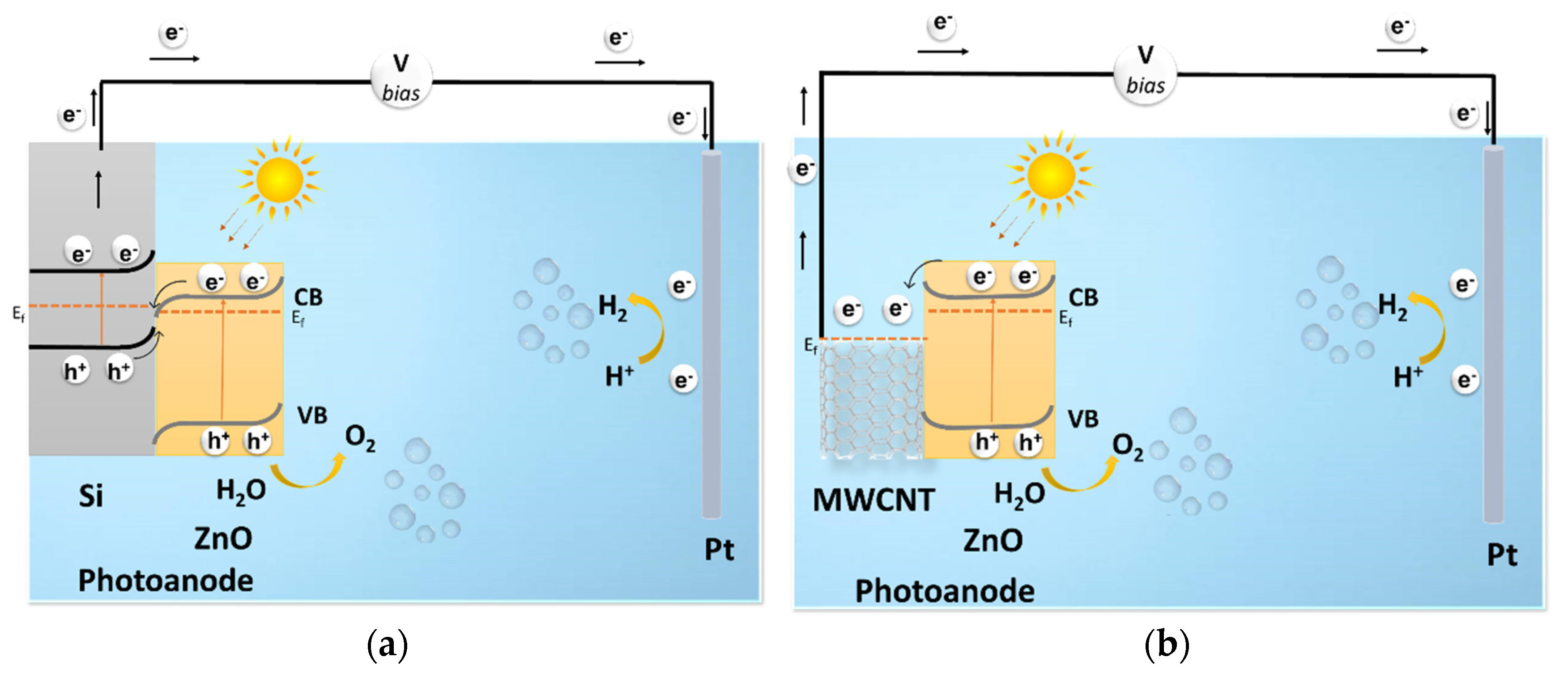
  • Transfer across the interface layer for the oxygen evolution reaction (OER) (faradaic process);
  • Recombination with electrons at the surface (non-faradaic);
  • Promotion of Zn2+ dissolution due to a reaction with the unsaturated O2− of ZnO [17]. (Photo corrosion).
The high charge transfer resistance in Si-ZnO samples (Figures S3 and S4, Tables S1 and S2) along with the slow OER kinetics leads to the accumulation of charges at the surface, which enhances the photo-corrosion. Various approaches have been reported, in the context of the photocatalytic organic dye degradation, for the limitation of ZnO photo-corrosion. This includes hybridization with a co-catalyst or with carbon, and the formation of heterojunctions [17]. The photo-corrosion enhances with the application of a bias voltage [19], which makes the ZnO photo-corrosion in water-splitting applications more critical. ZnO nanostructures degrade severely under an applied bias voltage and light illumination in different electrolytes such as Na2SO4 [50] and NaOH [39]. The protection of their surface with carbon [29], C3N4 [35], RGO [33,34] or oxides (TiO2 [21], V2O5 [65] and BiVO4 [66]) have been reported as a means to improve the photo stability and, at best, a loss of photocurrent was noticed at 40% after 4 h of light illumination under a bias voltage.
The heterostructures investigated in the present study are CNT-ZnO core–shell with a direct ZnO exposition to the electrolyte. The photo-corrosion of this heterostructure is compared to Si-ZnO in Figure 7. As far as Si-ZnO is concerned, a loss of 80% of the photocurrent occurs after ~50, 200 and >500 min for the 62, 138 and 275 nm thick ZnO, respectively (Figure S5). In all the cases, the initial rise in the photocurrent, with continuous light illumination and an external bias, is attributed to a change at the ZnO surface to Zinc hydroxide [63]. This is followed with a decrease in photocurrent due to photo-corrosion of the ZnO surface [61,66]. Assuming a constant absorption coefficient and a complete light penetration depth, an average ZnO dissolution rate of 0.8 nm/min could be estimated for the grown ZnO on Si. A substantially higher dissolution rate, 40 nm/min, was reported for ZnO film with a thickness of 800 nm made by a hydrothermal process [67]. This relatively low dissolution rate might be the result of a pin hole free ZnO made by ALD. The ZnO dissolution rate was estimated at 0.024 nm/min for the CNT-ZnO samples (ultrathin ZnO films: 8 and 34 nm), which is substantially low. As no passivation was implemented in this case, the surface kinetics would remain unchanged. The porosity of the CNT-ZnO core–shell structure is suspected to play a determinant role by limiting the Zn2+ outward diffusion in the electrolyte, which slows down the coating’s degradation. The CNT-ZnO sample with a shell thickness of 74 nm features a photocurrent density of 0.55 mA/cm2 and a stability of 8 h under 1 sun illumination and a bias voltage of 1.23 VRHE. As displayed in Table 1, these results are appealing relative to literature data.

4. Conclusions

The gas-phase CVD-ALD process was used to synthesis porous CNT-ZnO nanocomposite film on silicon substrates. The CNTs deposited via thermal CVD in this work are randomly oriented and feature a low density, whereas the subsequent ALD enables the growth of a polycrystalline wurtzite ZnO shell around the individual CNTs. The photoelectrochemical characteristics of the so formed Si-CNT-ZnO were investigated and compared to a directly grown ZnO on Si (Si-ZnO). The ZnO in these cases was investigated as an anode material for the photo-electrochemical water splitting reaction. The Si-CNT-ZnO reveals a nearly 5-fold increase of the photocurrent density relative to Si-ZnO samples, where ZnO features a comparable thickness. This improvement was correlated to the enhancement of electron–hole separation and surface area. CNT acts as an efficient electron collector with a fast 1D electron transport. Furthermore, the CNT-ZnO core–shell structure features an enhanced photo-corrosion stability relative to bare ZnO.

Supplementary Materials

The following are available online at https://www.mdpi.com/article/10.3390/coatings12010047/s1, Figure S1: Linear sweep measurements at 0.1 V/s of CNT-ZnO (left), Si-ZnO (right); Figure S2: Onset potential for both the configurations with varied ZnO thickness (left) and the chronoamperometric measurements of Si-ZnO at 1.23 VRHE (right); Figure S3: Nyquist diagram of CNT-ZnO samples under dark, light at 1.23 VRHE, with a fitting electric circuit model parameter; Table S1: Electrical characteristics of the various ZnO thicknesses on CNT/silicon; Figure S4: Nyquist diagram of CNT-ZnO samples under dark and light conditions at 1.23 VRHE with a fitting electric circuit model parameter; Table S2: Electrical characteristics of the various ZnO thicknesses on silicon; Figure S5: Photocurrent stability for CNT-ZnO and Si-ZnO samples was measured in 0.1M NaOH solution (pH 12.7 (left) and in borate solution (right), under 1 sun illumination and a bias of 1.23 VRHE. The borate solution composition: 125 mL 0.05 M borate (Na2B4O7·10H2O) + 47 mL 0.2 M NaOH + 78 mL water.

Author Contributions

The conceptualization, methodology and data analysis were the result of a synergy between all authors; the synthesis of the materials was performed by N.B. and V.P.P.; whereas the photoelectrochemical characterization was done by A.M.H.F. and V.P.P.; the HIM characterization and its interpretation was done by J.-N.A.; the original draft was written by V.P.P.; the substantial review and editing was secured by N.B. All authors have read and agreed to the published version of the manuscript.

Funding

The authors would like to acknowledge funding through the MASSENA Pride program of the Luxembourg National Research Fund (Grant No. FNR PRIDE/MASSENA/15/10935404). The photo-electrochemical test bench is part of a project that has received funding from the European Research Council (ERC) under the European Union’s Horizon 2020 research and innovation programme (Grant No. 865985).

Institutional Review Board Statement

Not applicable.

Informed Consent Statement

Not applicable.

Data Availability Statement

Data sharing is not applicable to this article.

Conflicts of Interest

The authors declare no conflict of interest.

References

  1. Varghese, O.K.; Grimes, C.A. Appropriate strategies for determining the photoconversion efficiency of water photoelectrolysis cells: A review with examples using titania nanotube array photoanodes. Sol. Energy Mater. Sol. Cells 2008, 92, 374–384. [Google Scholar] [CrossRef]
  2. Panwar, N.L.; Kaushik, S.C.; Kothari, S. Role of renewable energy sources in environmental protection: A review. Renew. Sustain. Energy Rev. 2011, 15, 1513–1524. [Google Scholar] [CrossRef]
  3. PennState, 9.4. Hydrogen Storage. Available online: https://www.e-education.psu.edu/eme812/node/726 (accessed on 20 January 2021).
  4. Ogden, J.M. Prospects for building a hydrogen energy infrastructure. Annu. Rev. Energy Environ. 1999, 24, 227–279. [Google Scholar] [CrossRef]
  5. Kim, J.H.; Hansora, D.; Sharma, P.; Jang, J.W.; Lee, J.S. Toward practical solar hydrogen production-an artificial photosynthetic leaf-to-farm challenge. Chem. Soc. Rev. 2019, 48, 1908–1971. [Google Scholar] [CrossRef] [PubMed]
  6. Yao, T.; An, X.; Han, H.; Chen, J.Q.; Li, C. Photoelectrocatalytic materials for solar water splitting. Adv. Energy Mater. 2018, 8, 1–36. [Google Scholar] [CrossRef]
  7. Yang, W.; Prabhakar, R.R.; Tan, J.; Tilley, S.D.; Moon, J. Strategies for enhancing the photocurrent, photovoltage, and stability of photoelectrodes for photoelectrochemical water splitting. Chem. Soc. Rev. 2019, 48, 4979–5015. [Google Scholar] [CrossRef]
  8. Ros, C.; Andreu, T.; Morante, J.R. Photoelectrochemical water splitting: A road from stable metal oxides to protected thin film solar cells. J. Mater. Chem. A 2020, 8, 10625–10669. [Google Scholar] [CrossRef]
  9. Li, J.; Wu, N. Semiconductor-based photocatalysts and photoelectrochemical cells for solar fuel generation: A review. Catal. Sci. Technol. 2015, 5, 1360–1384. [Google Scholar] [CrossRef]
  10. Chen, S.; Wang, L.W. Thermodynamic oxidation and reduction potentials of photocatalytic semiconductors in aqueous solution. Chem. Mater. 2012, 24, 3659–3666. [Google Scholar] [CrossRef] [Green Version]
  11. Jiang, C.; Moniz, S.J.A.; Wang, A.; Zhang, T.; Tang, J. Photoelectrochemical devices for solar water splitting-materials and challenges. Chem. Soc. Rev. 2017, 46, 4645–4660. [Google Scholar] [CrossRef] [Green Version]
  12. Osterloh, F.E. Inorganic nanostructures for photoelectrochemical and photocatalytic water splitting. Chem. Soc. Rev. 2013, 42, 2294–2320. [Google Scholar] [CrossRef]
  13. Kumar, S.G.; Rao, K.S.R.K. Zinc oxide based photocatalysis: Tailoring surface-bulk structure and related interfacial charge carrier dynamics for better environmental applications. RSC Adv. 2015, 5, 3306–3351. [Google Scholar] [CrossRef]
  14. Shaikh, A.F.; Arbuj, S.S.; Tamboli, M.S.; Naik, S.D.; Rane, S.B.; Kale, B.B. ZnSe/ZnO nano-heterostructures for enhanced solar light hydrogen generation. ChemistrySelect 2017, 2, 9174–9180. [Google Scholar] [CrossRef]
  15. Kegel, J.; Povey, I.M.; Pemble, M.E. Zinc oxide for solar water splitting: A brief review of the material’s challenges and associated opportunities. Nano Energy 2018, 54, 409–428. [Google Scholar] [CrossRef]
  16. McCafferty, E. Thermodynamics of corrosion: Pourbaix diagrams. In Introduction to Corrosion Science; Springer: New York, NY, USA, 2010; p. 328. [Google Scholar]
  17. Becker, J.P.; Pust, S.E.; Hüpkes, J. Effects of the electrolyte species on the electrochemical dissolution of polycrystalline ZnO:Al thin films. Electrochim. Acta 2013, 112, 976–982. [Google Scholar] [CrossRef] [Green Version]
  18. Weng, B.; Qi, M.Y.; Han, C.; Tang, Z.R.; Xu, Y.J. Photocorrosion inhibition of semiconductor-based photocatalysts: Basic principle, current development, and future perspective. ACS Catal. 2019, 9, 4642–4687. [Google Scholar] [CrossRef]
  19. Fekete, M.; Riedel, W.; Patti, A.F.; Spiccia, L. Photoelectrochemical water oxidation by screen printed ZnO nanoparticle films: Effect of pH on catalytic activity and stability. Nanoscale 2014, 6, 7585–7593. [Google Scholar] [CrossRef]
  20. Liu, C.F.; Lu, Y.J.; Hu, C.C. Effects of anions and ph on the stability of ZnO nanorods for photoelectrochemical water splitting. ACS Omega 2018, 3, 3429–3439. [Google Scholar] [CrossRef]
  21. Liu, M.; Nam, C.Y.; Black, C.T.; Kamcev, J.; Zhang, L. Enhancing water splitting activity and chemical stability of zinc oxide nanowire photoanodes with ultrathin titania shells. J. Phys. Chem. C 2013, 117, 13396–13402. [Google Scholar] [CrossRef]
  22. Reddy, N.K.; Winkler, S.; Koch, N.; Pinna, N. Electrochemical water oxidation of ultrathin cobalt oxide-based catalyst supported onto aligned ZnO nanorods. ACS Appl. Mater. Interfaces 2016, 8, 3226–3232. [Google Scholar] [CrossRef]
  23. Shao, M.; Ning, F.; Wei, M.; Evans, D.G.; Duan, X. Hierarchical nanowire arrays based on ZnO core-layered double hydroxide shell for largely enhanced photoelectrochemical water splitting. Adv. Funct. Mater. 2014, 24, 580–586. [Google Scholar] [CrossRef]
  24. Mao, Y.; Cheng, Y.; Wang, J.; Yang, H.; Li, M.; Chen, J.; Chao, M.; Tong, Y.; Liang, E. Amorphous NiO electrocatalyst overcoated ZnO nanorod photoanodes for enhanced photoelectrochemical performance. New J. Chem. 2016, 40, 107–112. [Google Scholar] [CrossRef]
  25. Li, C.; Wang, T.; Luo, Z.; Zhang, D.; Gong, J. Transparent ALD-grown Ta2O5 protective layer for highly stable ZnO photoelectrode in solar water splitting. Chem. Commun. 2015, 51, 7290–7293. [Google Scholar] [CrossRef]
  26. El-Shazly, A.N.; Hegazy, A.H.; Rashad, M.M.; El-Shahat, M.F.; Allam, N.K. Ultrathin ALD TiO2 shells for enhanced photoelectrochemical solar fuel generation. J. Alloy. Compd. 2018, 739, 178–183. [Google Scholar] [CrossRef]
  27. Scheuermann, A.G.; McIntyre, P.C. Atomic Layer Deposited Corrosion Protection: A Path to Stable and Efficient Photoelectrochemical Cells. J. Phys. Chem. Lett. 2016, 7, 2867–2878. [Google Scholar] [CrossRef] [PubMed]
  28. Li, Z.; Feng, S.; Liu, S.; Li, X.; Wang, L.; Lu, W. A three-dimensional interconnected hierarchical FeOOH/TiO2/ZnO nanostructural photoanode for enhancing the performance of photoelectrochemical water oxidation. Nanoscale 2015, 7, 19178–19183. [Google Scholar] [CrossRef] [PubMed]
  29. Hernández, S.; Cauda, V.; Chiodoni, A.; Dallorto, S.; Sacco, A.; Hidalgo, D.; Celasco, E.; Pirri, C.F. Optimization of 1D ZnO@TiO2 core-shell nanostructures for enhanced photoelectrochemical water splitting under solar light illumination. ACS Appl. Mater. Interfaces 2014, 6, 12153–12167. [Google Scholar] [CrossRef] [PubMed]
  30. Sun, X.; Li, Q.; Jiang, J.; Mao, Y. Morphology-tunable synthesis of ZnO nanoforest and its photoelectrochemical performance. Nanoscale 2014, 6, 8769–8780. [Google Scholar] [CrossRef]
  31. Jeong, K.; Deshmukh, P.R.; Park, J.; Sohn, Y.; Shin, W.G. ZnO-TiO2 core-shell nanowires: A sustainable photoanode for enhanced photoelectrochemical water splitting. ACS Sustain. Chem. Eng. 2018, 6, 6518–6526. [Google Scholar] [CrossRef]
  32. Hassan, M.A.; Waseem, A.; Johar, M.A.; Bagal, I.V.; Ha, J.S.; Ryu, S.W. Single-step fabrication of 3D hierarchical ZnO/ZnS heterojunction branched nanowires by MOCVD for enhanced photoelectrochemical water splitting. J. Mater. Chem. A 2020, 8, 8300–8312. [Google Scholar] [CrossRef]
  33. Hu, W.-C.; Chen, Y.-A.; Hsieh, P.-Y.; Tsao, C.-W.; Chiu, Y.-H.; Chang, T.-F.M.; Chen, C.-Y.; Sone, M.; Hsu, Y.-J. Reduced graphene oxides-wrapped ZnO with notable photocatalytic property. J. Taiwan Inst. Chem. Eng. 2020, 112, 337–344. [Google Scholar] [CrossRef]
  34. Zhang, Z.; Choi, M.; Baek, M.; Hwang, I.; Cho, C.; Deng, Z.; Lee, J.; Yong, K. Design and roles of RGO-wrapping in charge transfer and surface passivation in photoelectrochemical enhancement of cascade-band photoanode. Nano Res. 2017, 10, 2415–2430. [Google Scholar] [CrossRef]
  35. Liu, C.; Qiu, Y.; Wang, F.; Wang, K.; Liang, Q.; Chen, Z. Design of core–shell-structured ZnO/ZnS hybridized with graphite-like c3n4 for highly efficient photoelectrochemical water splitting. Adv. Mater. Interfaces 2017, 4, 1–11. [Google Scholar] [CrossRef]
  36. Fu, H.; Xu, T.; Zhu, S.; Zhu, Y. Photocorrosion inhibition and enhancement of photocatalytic activity for ZnO via hybridization with C60. Environ. Sci. Technol. 2008, 42, 8064–8069. [Google Scholar] [CrossRef]
  37. Choi, H.; Lee, N.; Park, H.; Choi, Y.; Yuk, H.; Lee, J.; Lee, S.J.; Lee, E.J.; Jeon, H. Tuning the electronic band structure and optoelectrical characteristics of ALD-grown Zn(O,S) buffer layers for SnS solar cells. Optik 2021, 228, 165921. [Google Scholar] [CrossRef]
  38. Shiraishi, M.; Ata, M. Work function of carbon nanotubes. Carbon N. Y. 2001, 39, 1913–1917. [Google Scholar] [CrossRef]
  39. Sharma, A.K.; Sharma, R. Fabrication and characterization of zinc oxide/multi-walled carbon nanotube Schottky barrier diodes. J. Electron. Mater. 2018, 47, 3037–3044. [Google Scholar] [CrossRef]
  40. Marinho, B.; Ghislandi, M.; Tkalya, E.; Koning, C.E.; de With, G. Electrical conductivity of compacts of graphene, multi-wall carbon nanotubes, carbon black, and graphite powder. Powder Technol. 2012, 221, 351–358. [Google Scholar] [CrossRef]
  41. Chaudhary, D.; Singh, S.; Vankar, V.D.; Khare, N. ZnO nanoparticles decorated multi-walled carbon nanotubes for enhanced photocatalytic and photoelectrochemical water splitting. J. Photochem. Photobiol. A Chem. 2018, 351, 154–161. [Google Scholar] [CrossRef]
  42. Vietmeyer, F.; Seger, B.; Kamat, P.V. Anchoring ZnO particles on functionalized single wall carbon nanotubes. Excited state interactions and charge collection. Adv. Mater. 2007, 19, 2935–2940. [Google Scholar] [CrossRef]
  43. Li, M.; Chang, K.; Wang, T.; Liu, L.; Zhang, H.; Li, P.; Ye, J. Hierarchical nanowire arrays based on carbon nanotubes and Co3O4 decorated ZnO for enhanced photoelectrochemical water oxidation. J. Mater. Chem. A 2015, 3, 13731–13737. [Google Scholar] [CrossRef] [Green Version]
  44. Wei, Y.; Du, H.; Kong, J.; Lu, X.; Ke, L.; Sun, X.W. Multi-walled carbon nanotubes modified ZnO nanorods: A photoanode for photoelectrochemical cell. Electrochim. Acta 2014, 143, 188–195. [Google Scholar] [CrossRef]
  45. Park, J.G.; Cheng, Q.; Lu, J.; Bao, J.; Li, S.; Tian, Y.; Liang, Z.; Zhang, C.; Wang, B. Thermal conductivity of MWCNT/epoxy composites: The effects of length, alignment and functionalization. Carbon N. Y. 2012, 50, 2083–2090. [Google Scholar] [CrossRef]
  46. Prasadam, V.P.; Ramirez, F.V.; Papakonstantinou, I.; Parkin, I.P.; Bahlawane, N. Thermoresponsive black VO2 –carbon nanotube composite coatings for solar energy harvesting. ACS Appl. Nano Mater. 2020, 3, 8848–8857. [Google Scholar] [CrossRef]
  47. Coy, E.; Siuzdak, K.; Pavlenko, M.; Załęski, K.; Graniel, O.; Ziółek, M.; Balme, S.; Miele, P.; Weber, M.; Bechelany, M.; et al. Enhancing photocatalytic performance and solar absorption by schottky nanodiodes heterojunctions in mechanically resilient palladium coated TiO2/Si nanopillars by atomic layer deposition. Chem. Eng. J. 2020, 392, 123702. [Google Scholar] [CrossRef]
  48. Ma, D.; Shi, J.W.; Zou, Y.; Fan, Z.; Ji, X.; Niu, C.; Wang, L. Rational design of CdS@ZnO core-shell structure via atomic layer deposition for drastically enhanced photocatalytic H2 evolution with excellent photostability. Nano Energy 2017, 39, 183–191. [Google Scholar] [CrossRef] [Green Version]
  49. Wang, C.C.; Chou, C.Y.; Yi, S.R.; Chen, H.D. Deposition of heterojunction of ZnO on hydrogenated TiO2 nanotube arrays by atomic layer deposition for enhanced photoelectrochemical water splitting. Int. J. Hydrogen Energy 2019, 44, 28685–28697. [Google Scholar] [CrossRef]
  50. Kulmas, M.; Paterson, L.; Höflich, K.; Bashouti, M.Y.; Wu, Y.; Göbelt, M.; Ristein, J.; Bachmann, J.; Meyer, B.; Christiansen, S. Composite Nanostructures of TiO2 and ZnO for water splitting application: Atomic layer deposition growth and density Functional Theory Investigation. Adv. Funct. Mater. 2016, 26, 4882–4889. [Google Scholar] [CrossRef]
  51. Pavlenko, M.; Siuzdak, K.; Coy, E.; Załęski, K.; Jancelewicz, M.; Iatsunskyi, I. Enhanced solar-driven water splitting of 1D core-shell Si/TiO2/ZnO nanopillars. Int. J. Hydrogen Energy 2020, 45, 26426–26433. [Google Scholar] [CrossRef]
  52. Basheer, H.J.; Pachot, C.; Lafont, U.; Devaux, X.; Bahlawane, N. Low-temperature thermal CVD of superblack carbon nanotube coatings. Adv. Mater. Interfaces 2017, 4, 1–9. [Google Scholar] [CrossRef] [Green Version]
  53. Basheer, H.J.; Baba, K.; Bahlawane, N. Thermal conversion of ethanol into carbon nanotube coatings with adjusted packing density. ACS Omega 2019, 4, 10405–10410. [Google Scholar] [CrossRef] [PubMed]
  54. Prasadam, V.P.; Gautier, N.; Bahlawane, N. CNT nanoengineering for thermally stable selective solar absorption. Mater. Today Commun. 2021, 28, 102552. [Google Scholar] [CrossRef]
  55. Yamada, A.; Sang, B.; Konagai, M. Atomic layer deposition of ZnO transparent conducting oxides. Appl. Surf. Sci. 1997, 112, 216–222. [Google Scholar] [CrossRef]
  56. Wang, R.P.; Xu, G.; Jin, P. Size dependence of electron-phonon coupling in ZnO nanowires. Phys. Rev. B-Condens. Matter Mater. Phys. 2004, 69, 5–8. [Google Scholar] [CrossRef]
  57. Basheer, H.J.; Baba, K.; Bahlawane, N. Thermal chemical vapor deposition of superblack randomly oriented carbon nanotube coatings. Phys. Status Solidi (A) 2020, 217, 1900704. [Google Scholar] [CrossRef]
  58. Blanksby, S.J.; Ellison, B.G. Bond dissociation energies of organic molecules. Acc. Chem. Res. 2003, 36, 255–263. [Google Scholar] [CrossRef]
  59. Haschke, S.; Mader, M.; Schlicht, S.; Roberts, A.M.; Angeles-Boza, A.M.; Barth, J.A.; Bachmann, J. Direct oxygen isotope effect identifies the rate-determining step of electrocatalytic OER at an oxidic surface. Nat. Commun. 2018, 9, 4565. [Google Scholar] [CrossRef] [PubMed]
  60. Doepke, A.; Han, C.; Back, T.; Cho, W.; Dionysiou, D.D.; Shanov, V.; Halsall, H.B.; Heineman, W.R. Analysis of the electrochemical oxidation of multiwalled carbon nanotube tower electrodes in sodium hydroxide. Electroanalysis 2012, 24, 1501–1508. [Google Scholar] [CrossRef]
  61. Govatsi, K.; Seferlis, A.; Neophytides, S.G.; Yannopoulos, S.N. Influence of the morphology of ZnO nanowires on the photoelectrochemical water splitting efficiency. Int. J. Hydrogen Energy 2018, 43, 4866–4879. [Google Scholar] [CrossRef]
  62. Yang, H.; Kim, E.; Kim, S.H.; Jeong, M.S.; Shin, H. Hole trap, charge transfer and photoelectrochemical water oxidation in thickness-controlled TiO2 anatase thin films. Appl. Surf. Sci. 2020, 529, 147020. [Google Scholar] [CrossRef]
  63. Paulauskas, I.E.; Jellison, G.E.; Boatner, L.A.; Brown, G.M. Photoelectrochemical stability and alteration products of n-type single-crystal zno photoanodes. Int. J. Electrochem. 2011, 2011, 1–10. [Google Scholar] [CrossRef] [Green Version]
  64. Souza, F.L.; Lopes, K.P.; Longo, E.; Leite, E.R. The influence of the film thickness of nanostructured α-Fe2O3 on water photooxidation. Phys. Chem. Chem. Phys. 2009, 11, 1215–1219. [Google Scholar] [CrossRef]
  65. Septiani, N.L.W.; Saputro, A.G.; Kaneti, Y.V.; Maulana, A.L.; Fathurrahman, F.; Lim, H.; Yuliarto, B.; Nugraha; Dipojono, H.K.; Golberg, D.; et al. Hollow zinc oxide microsphere-multiwalled carbon nanotube composites for selective detection of sulfur dioxide. ACS Appl. Nano Mater. 2020, 3, 8982–8996. [Google Scholar] [CrossRef]
  66. Ida, S.; Kearney, K.; Futagami, T.; Hagiwara, H.; Sakai, T.; Watanabe, M.; Rockett, A.; Ishihara, T. Photoelectrochemical H2 evolution using TiO2-coated CaFe2O4 without an external applied bias under visible light irradiation at 470 nm based on device modeling. Sustain. Energy Fuels 2017, 1, 280–287. [Google Scholar] [CrossRef]
  67. Pawar, A.U.; Kim, C.W.; Kang, M.J.; Kang, Y.S. Crystal facet engineering of ZnO photoanode for the higher water splitting efficiency with proton transferable nafion film. Nano Energy 2016, 20, 156–167. [Google Scholar] [CrossRef]
  68. Xie, S.; Lu, X.; Zhai, T.; Li, W.; Yu, M.; Liang, C.; Tong, Y. Enhanced photoactivity and stability of carbon and nitrogen co-treated ZnO nanorod arrays for photoelectrochemical water splitting. J. Mater. Chem. 2012, 22, 14272–14275. [Google Scholar] [CrossRef]
  69. Wang, J.; Wang, G.; Jiang, J.; Wan, Z.; Su, Y.; Tang, H. Insight into charge carrier separation and solar-light utilization: rGO decorated 3D ZnO hollow microspheres for enhanced photocatalytic hydrogen evolution. J. Colloid Interface Sci. 2020, 564, 322–332. [Google Scholar] [CrossRef] [PubMed]
Figure 1. SEM observation of pristine CNT film (a) and of Si-CNT-ZnO-18 nm (b).
Coatings 12 00047 g001
Figure 2. (a) HIM observation of CNT-ZnO structures; (b,c) higher magnification images after a cut using gallium ion beam. The micrographs feature a polycrystalline 18 nm-thick ZnO shell around CNT cores with a diameter of 12 nm.
Coatings 12 00047 g002
Figure 3. XRD spectra of the CNT-ZnO coatings on silicon (a) with the extracted crystallite size (b); and their respective Raman spectra (c).
Coatings 12 00047 g003
Figure 4. Chronoamperometric measurements at 1.23 VRHE (a) and the cyclic voltammetry at 0.1 V/s sweep rate for the noncoated and ZnO-coated Si (b) and Si-CNT (c) substrates. The thickness of ZnO is 74 nm on the CNTs and of 62 nm on Si.
Coatings 12 00047 g004
Figure 5. Chronoamperometric measurements at 1.23 VRHE of various ZnO thicknesses on CNT (a) and the compared thickness-dependent photocurrent with films on planar Si substrates (b).
Coatings 12 00047 g005
Figure 6. Schematic of PEC water splitting mechanism for Si-ZnO (a) and CNT-ZnO (b) photoanodes.
Coatings 12 00047 g006
Figure 7. Photocurrent stability measured in a 0.1 M NaOH solution (pH 12.7), under a 1 sun illumination and a bias of 1.23 VRHE, for various ZnO thicknesses on Si and on Si-CNT.
Coatings 12 00047 g007
Table 1. State-of-art of carbon-ZnO composite material studied for photo-corrosion stability.
MaterialSynthesis/RemarkDimensionsCurrent DensityReference
ZnO thin film covered with nafionHydrothermal/
enhancement by (002) crystal facet orientation
ZnO thickness of 800 nm; nafion thickness of 2.5 µm 0.4 mA·cm−2 (1.23 VRHE)
photocurrent stability for 5 h
[67]
ZnO rods covered with C3N4 layerElectrodeposition/
enhancement by surface passivation
ZnO rods of 2 µm length; C3N4 of 15 nm thickness0.45 mA·cm−2 (1.23 VRHE)
photocurrent stability for 1 h
[68]
ZnO rods covered with C3N4 sheets in-between Electrodeposition/
enhancement by surface passivation
400 nm ZnO rod arrays 0.4 mA·cm−2 (1.23 VRHE)
photocurrent stability for 1 h
[35]
RGO dispersed between ZnO sphereSolvothermal/
enhancement by heterostructure
1–2 µm diameter ZnO sphere0.1 mA·cm−2 (1.23 VRHE)
photocurrent stability for 3 h
[69]
ZnO particle on CNT composite Sol-Gel/enhancement by heterostructure30 nm ZnO particle 0.45 mA·cm−2 (1.23 VRHE)
photocurrent stability for 20 min
[41]
CNT-ZnO
core–shell nanocomposite
CVD-ALD/enhancement by heterostructure3 µm thick-CNT film; 74 nm thickness-ZnO shell layer0.55 mA·cm−2 (1.23 VRHE)
photocurrent stability for 8 h
Present work
Publisher’s Note: MDPI stays neutral with regard to jurisdictional claims in published maps and institutional affiliations.

