Article

Process Simulation and Abrasion Behavior of Jet Electrodeposited Ni–TiN Nanocoatings

1
College of Civil Engineering and Water Conservancy, Heilongjiang Bayi Agricultural University, Daqing 163319, China
2
College of Engineering, Heilongjiang Bayi Agricultural University, Daqing 163319, China
3
The Third Construction Engineering Company Co., Ltd. of China Construction Second Engineering Bureau, Beijing 100036, China
*
Author to whom correspondence should be addressed.
Coatings 2022, 12(1), 86; https://doi.org/10.3390/coatings12010086
Submission received: 16 December 2021 / Revised: 2 January 2022 / Accepted: 6 January 2022 / Published: 12 January 2022
(This article belongs to the Special Issue State-of-the-Art on Coatings Research in Asia)

Abstract

:
In this work, we study jet-electrodeposited Ni–TiN composite nanocoatings (CNCs) for improving abrasion resistance as a function of various nozzle diameters. In addition, COMSOL software is utilized to simulate the process of jet electrodeposition, particularly the influence of spraying speed and pressure of the electrolyte on the abrasion resistance of coatings. Optimization of the nozzle diameter to obtain uniform and high-performance coatings showed that a Φ7 mm nozzle diameter generated the optimum spraying speed and spraying pressure, which results in good micro-hardness and abrasion resistance of the Ni–TiN CNCs. Under these conditions, the 45 steel substrates are coated with a compact layer of uniform and nano-sized TiN particles, which are responsible for the high abrasion resistance of our Ni–TiN CNCs. Our study may motivate researchers to study jet electrodeposition in order to obtain abrasion-resistant coatings.

1. Introduction

In the recent decades, the traditional manufacturing industry began to shift to the advanced manufacturing industry (such as digital and intelligent fields). The abrasion resistance of pure nickel metal is not sufficient to match with the high-performance requirements of an advanced manufacturing industry. The nickel matrix composite coatings with excellent abrasion resistance are widely used in the aerospace, marine engineering, water transmission pipe, bearings, machinery and other fields [1,2,3,4,5,6,7,8]. The nano-sized particles of SiC, TiN, Al2O3, etc., owing to their excellent physical and chemical properties, were introduced into the metal matrix crystal grains for preparing metal matrix composite coatings, which further expanded the application fields of nano-size particles. Xia et al. [9] prepared Ni–Al2O3 composite nanocoatings (CNCs) on the surface of Q235 steel substrate via an ultrasonic-assisted jet pulse electrodeposition method. The process resulted in the coating of agglomeration free coating of nano-size Al2O3 particles due to which corrosion resistance of Ni–Al2O3 CNCs was distinctly improved. Jiang et al. [10] produced the Ni–Co-SiC CNCs on the surface of the A3 steel substrate via a magnetic field-assisted JED method, which significantly enhanced the micro-hardness and corrosion resistance of the steel substrates. Recently, Ma et al. [11] used an AR model in the MATLAB software for predicting the micro-hardness of Ni–TiN CNCs. These results show that, embedding nano-sized particles into the metal matrix through electrodeposition technology is an effective approach for improving the performance of composite coatings.
Traditional preparation methods of the nickel matrix composite coatings include the electrodeposition method, the hot-melt plating method, the chemical deposition method, etc. The jet electrodeposition technology as a branch of electrodeposition has many merits (simple operation, low cost, excellent deposition performance etc.), and is considered to be the main method for preparing surface protection layers [12,13,14,15,16,17,18]. Nano-sized TiN particles were introduced into the electrolyte to manufacture composite coatings of high micro-hardness and a strong abrasion resistance on the metal matrix via jet electrodeposition technology, which enhanced properties of the surface of mechanical parts [19,20,21,22]. While there are some reports on employing jet electrodeposition for coating TiN, there are few reports concerning the simulation of the spraying speed and the spraying pressure of the electrolyte via COMSOL software. Furthermore, the research reports on the structure and abrasion resistance of the jet-electrodeposited Ni–TiN CNCs lack complete performance optimization [23,24,25,26]. Herein, we aim to improve the abrasion resistance of Ni–TiN CNCs and to employ the COMSOL software (version 5.6) for the simulation process for optimizing the spray nozzle diameter. The simulation results regarding the effect of spraying speed and spraying pressure of the electrolyte on Ni–TiN CNCs manufactured at different nozzle diameters were consistent with that of the experimental data.

2. Experimental Procedure

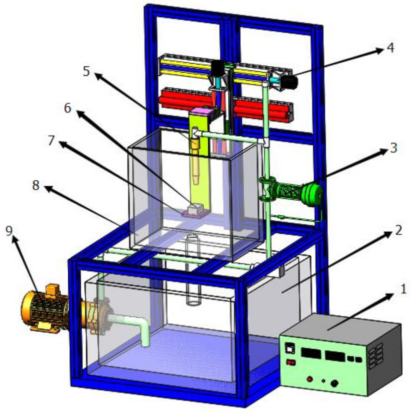
2.1. Preparation Process

The 45 steel block of 30 mm × 12 mm × 4 mm size (Anshan Iron and Steel Factory, Anshan, China) was selected as a cathode; different diameters (denoted as Nf) viz. Φ3, Φ5, Φ7, and Φ9 mm of nickel nozzle (Anshan Iron and Steel Factory, Anshan, China) were employed as anodes. Before electrodeposition, the surface of the 45 steel specimen was polished consecutively with 800 mesh, 1000 mesh, 1200 mesh and 1500 mesh metallographic sandpaper (Daqing Fengyuanxin Material Distribution Office, Daqing, China). The roughness of the specimen surface (Ra) was about 0.1 μm. Then, the polished specimen was subsequently treated with de-rusting liquid (Daqing Fengyuanxin Material Distribution Office, Daqing, China) and de-oil liquid (Daqing Fengyuanxin Material Distribution Office, Daqing, China). Finally, the deposed specimen was washed with the distilled water and was dried in air. The composition of the electrolyte used for the jet electrodeposition process of Ni–TiN CNCs is shown in Table 1. TiN nanoparticles were the inorganic nitride with a high hardness and a good chemical stability. In this article, TiN nanoparticles (average size 35 nm) were purchased from Shanghai Nanotechnology Co., Ltd. (Shanghai, China). The pH value of the electrolyte was adjusted to 4.3 by adding hydrochloric acid (3 mol/L) (Daqing Fengyuanxin Material Distribution Office, Daqing, China) or sodium hydrate solution (1 mol/L) (Daqing Fengyuanxin Material Distribution Office, Daqing, China). The electrolyte was heated and maintained at 50°C throughout the experiment using an immersion heating rod (Daqing Fengyuanxin Material Distribution Office, Daqing, China). The temperature was monitored using a thermometer inserted into the electrolyte. Figure 1 shows the schematics of the setup used for the jet electrodeposition process. The circulating flow module and the electrodeposition module were the main constituents of this system. The circulating flow module consisted of an electrolyte recovery module, a rotameter, a servo system, a nickel nozzle, an electrolytic cell and a reciprocating pump. The electrodeposition module consisted of a pulse electrical source, a 45 steel specimen and a platform. The CQB32-20-160 type reciprocating pump (Boshan Water Pump Machinery Factory, Zibo, China) played a role in recycling the liquid from the electrolyte tank into the circulating flow unit. Then, the recycled electrolyte was sprayed on the surface of the 45 steel surface using a flow-meter and a nickel nozzle. The flow rate of the electrolyte was set to 3 m3/h. The pole distance of 10 mm between the nickel nozzle and the cathode was controlled via a servo system. The power for the jet electrodeposition process was supplied by a SMD-60 style pulse power supply (Handan Electroplating Factory, Handan, China). A current density of 0.5 A/dm2 and an electrodeposition time of 50 min were selected, as those were reported to be optimum parameters to obtain superior performance in the literature.

2.2. Characterizations

The spraying speed and pressure of the electrolyte for preparing the Ni–TiN CNCs were simulated by utilizing COMSOL software (version 5.6) during the JED process. The surface morphologies of the Ni–TiN CNCs were monitored by utilizing a S3400 style scanning electron microscope (SEM) (Hitachi High-Tech Corporation, Tokyo, Japan). The TiN contents in the coatings were estimated by using an energy dispersive X-ray detector (EDX, INCA instrument, Oxford, UK). The phase structures of the Ni–TiN CNCs were determined by employing a D5000 style X-ray diffractometer (XRD) (Siemens, Munich, Germany). The test conditions were as described below: Cu Kα target, scanning range from 20° to 80°, and a scanning step of 0.01°. The average particle diameter (D) of the Ni–TiN composite coating was calculated by using Equation (1):
D = ()/(Bcosθ)
where K is the Scherrer constant whose value is 0.9, γ is X-ray wavelength (γ = 0.154056) nm, B is the FMHM of the peak, and θ represents Bragg angle.
The adhesion forces of the Ni–TiN CNCs were measured by utilizing an Elcometer 106/1-type attachment tester (Shanghai Measuring Instrument Factory, Shanghai, China). The micro-hardness of the Ni–TiN CNCs was determined by employing Hv-1000 Vickers micro-hardness tester (Shanghai Yuzhu Electro-machinical Equipment Co. Ltd., Shanghai, China). Test conditions were as follows: weight of the load 25 g, and the loading time of 10 s. The micro-hardness of the Ni–TiN CNCs was calculated by using Equation (2):
H = (1854.4 × 106 × 0.102F)/d2
where H is the Vickers micro-hardness, F is the vertical load, and d is the diagonal length of the indentation.
The abrasion resistance of Ni–TiN CNCs was measured by using an HSR-2M-style high-speed reciprocating friction tester (Shandong Jingcheng Friction & Wear Machine Factory, Jinan, Shandong, China). Test conditions were as follows: Counterbody of 40Cr quenched steel ball (60 HRC), rotation speed of 200 rpm, room temperature, vertical load of 5 N, loading time of 15 min, and a sliding length of 4.5 mm. The abrasion volume of Ni–TiN composite coating was calculated by using Equations (3) and (4):
V = π/3[r − (r2d2/4)1/2] × [3r − (r2d/2)]
where, V is the abrasion loss (mm3), r is the radius of the steel ball (mm) and d is the diameter of the coating abrasion (mm).
W = V/(SF)
where, W is abrasion rate of coating (mm3/N·m), V is abrasion loss (mm3), S represents sliding length (m), F is vertical loading load (N), which is automatically recorded friction coefficient with the high-speed reciprocating friction tester.

3. Results and Discussion

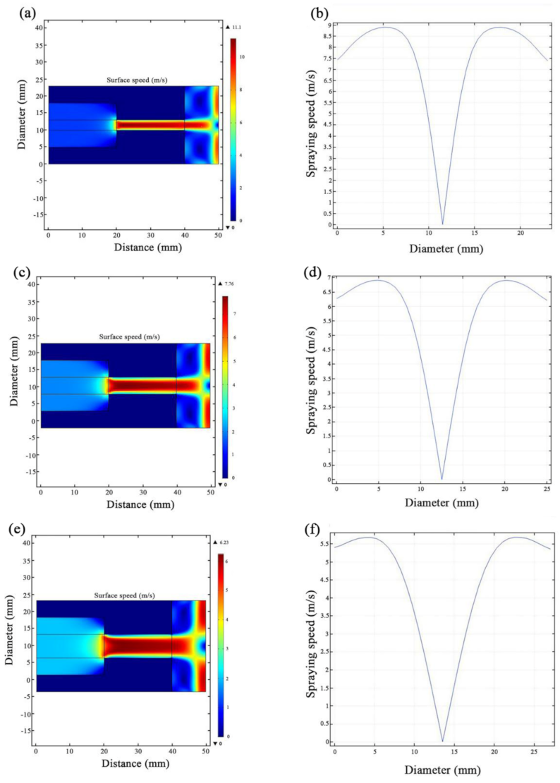
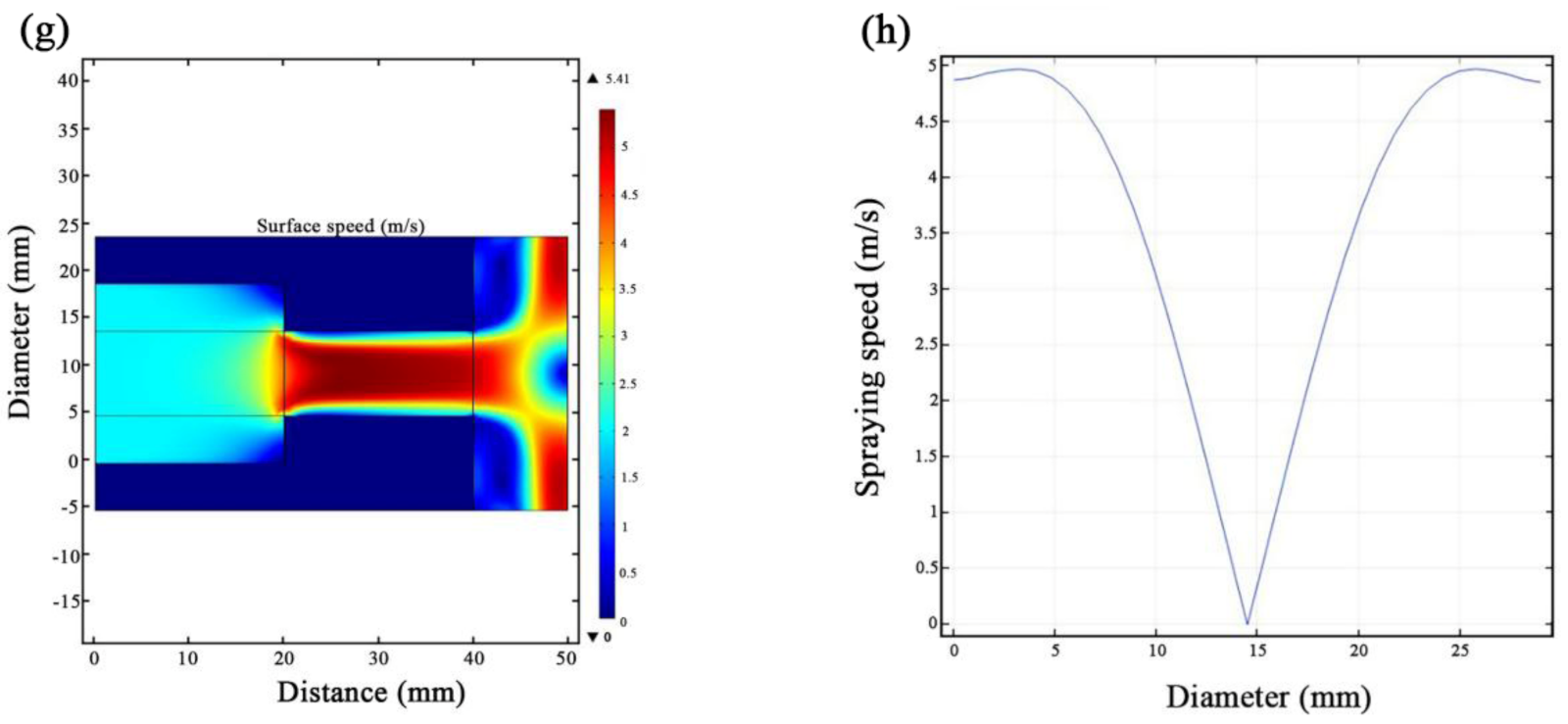
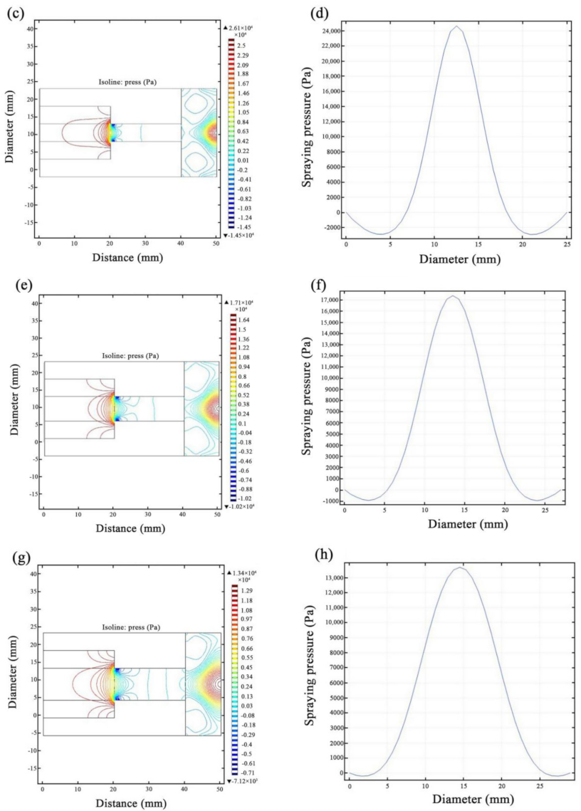
3.1. JED Simulations

The spraying speed and pressure of the electrolyte during the electrodeposition process were directly related to the nozzle diameter, as the initial spraying speed (2 m/s) of the electrolyte was kept constant. Excessive spraying speed and pressure led to an uneven distribution of TiN particles on the substrate surface. In addition, the TiN particles in the electrolyte produced large agglomerates, which would impair the structure and performance of the Ni–TiN CNCs. Therefore, it was necessary to simulate the effect of spraying speed and pressure of the electrolyte on the properties of jet electrodeposited Ni–TiN CNCs by using COMSOL 5.6 software. The simulation results are shown in Figure 2 and Figure 3. Figure 2a,c,e,g show the simulation cloud diagrams of the substrate subjected to a varying spraying speed of the electrolyte for preparing Ni–TiN CNCs during the JED process. In the process of manufacturing jet-electrodeposited Ni–TiN CNCs, the substrate was subjected to the decreasing spraying speed of the electrolyte using an increasing nozzle diameter. When the nozzle diameter was Φ3 mm, 45 steel substrate was subjected to the maximum spraying speed of the electrolyte of 11.1 m/s. When the nozzle diameter was increased to Φ5 mm, the substrate was subjected to the accelerated decreased spraying speed of the electrolyte. The maximum spraying speed of the electrolyte flowed from the nozzle diameter of Φ5 mm was 7.76 m/s. When the nozzle diameter was further increased to Φ7 mm, the spraying speed decreased to a maximum of 6.23 m/s. Finally, when the nozzle diameter was increased to Φ9 mm, the maximum spraying speed flow was 5.41 m/s. The results obtained from above simulation process was consistent with the experimentally observed values. The smaller the nozzle diameter, the greater the spraying speed of the electrolyte. This was due to constant velocity of electrolyte (2 m/s) used during the spraying process. The higher spraying speeds of the electrolyte passing through the nozzle resulted in the uneven spraying of the electrolyte.
Figure 3a,c,e,g show the simulation cloud diagrams of the substrate subjected to the varying spraying pressures of the electrolyte for preparing Ni–TiN CNCs during the JED process. Figure 3b,d,f,h are simulation number values of 45 steel substrate subjected to the spraying pressure of the electrolyte for preparing Ni–TiN CNCs during the JED process. During the JED process, the substrate was subjected to varying spraying pressures of the electrolyte by changing the nozzle diameter. When the nozzle diameter was Φ3 mm, the substrate was subjected to the highest spraying pressure of the electrolyte (5.66 × 10⁴ Pa)。 When the nozzle diameter was increased to Φ5 mm, the substrate was subjected to the spraying pressure of 2.61 × 10⁴ Pa. When the nozzle diameter was further increased to Φ7 mm, the spraying pressure was 1.71 × 10⁴ Pa. Finally, when the nozzle diameter was increased to Φ9 mm, the substrate was subjected to the spraying pressure of 1.34 × 10⁴ Pa. The above simulation phenomenon was consistent with the results reported by Liu et al. [27] The smaller the nozzle diameter, the substrate surface was subjected to a more uneven spraying pressure.

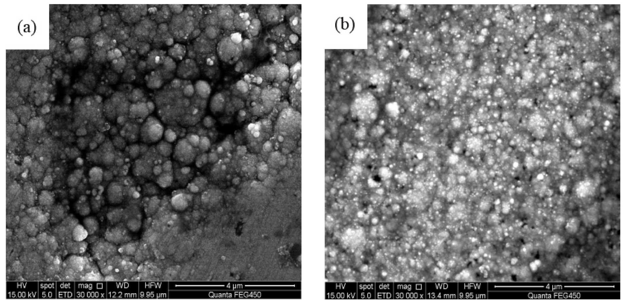
3.2. Analysis of Surface Morphology

Figure 4 shows SEM micrographs of jet electrodeposited Ni–TiN CNCs. It is possible to appreciate from Figure 4a that the smaller nozzle diameter of Φ3 mm results in uneven coating with crystal grains of varying sizes, numerous pores and protrusions, and loose structure. In addition, the Ni–TiN CNCs contained low number of TiN particles with serious agglomeration phenomenon. Figure 4b displays SEM micrographs of jet electrodeposited Ni–TiN CNCs at Φ5 mm nozzle diameter. Compared with that of Φ3 mm diameter, it possesses relatively even surface, obviously refined crystal grains, a smaller number of pores and protrusions, and enhanced distribution of TiN nanoparticles. Figure 4c revealed that the jet electrodeposited Ni–TiN CNCs obtained at Φ7 mm nozzle diameter contained flat surface, small and dense crystal grains, little pores and protrusions, and uniform distribution of TiN nanoparticles. Therefore, the Ni–TiN CNCs prepared at Φ7 mm nozzle diameter exhibited best performance. Figure 4d shows the jet electrodeposited Ni–TiN CNCs manufactured at Φ9 mm nozzle diameter. Compared to that of Φ7 mm diameter, it produced relatively uneven surface, obviously unrefined crystal grains, more pores and protrusions, and relatively severe agglomeration of TiN nanoparticles. This outcome is basically the same as the result revealed by Su et al. [28].
The appropriate spraying speed and pressure at Φ7 mm nozzle diameter during JED process resulted in best quality Ni–CNCs. Although the high spraying speed of electrolyte could supply more TiN nanoparticles in unit time between the substrate and the anode, the high spraying speed was beneficial to inhibit the growth of the Ni–TiN CNCs during JED process. In addition, the high spraying pressure would aggravate the particles agglomeration in the electrolyte, resulting in the low deposition speed of Ni crystal grains and TiN nanoparticles. This is due to the large agglomeration of TiN nanoparticle clusters did not provide new nucleation points for Ni grains during the co-deposition process. On the contrary, the low spraying speed and spraying pressure of the electrolyte led to the coarse morphology of the Ni–TiN CNCs. Therefore, the appropriate nozzle diameter could generate the more regular distribution of the electric-power lines between cathode and anode, which is beneficial for obtaining dense and uniform coatings [29,30,31].

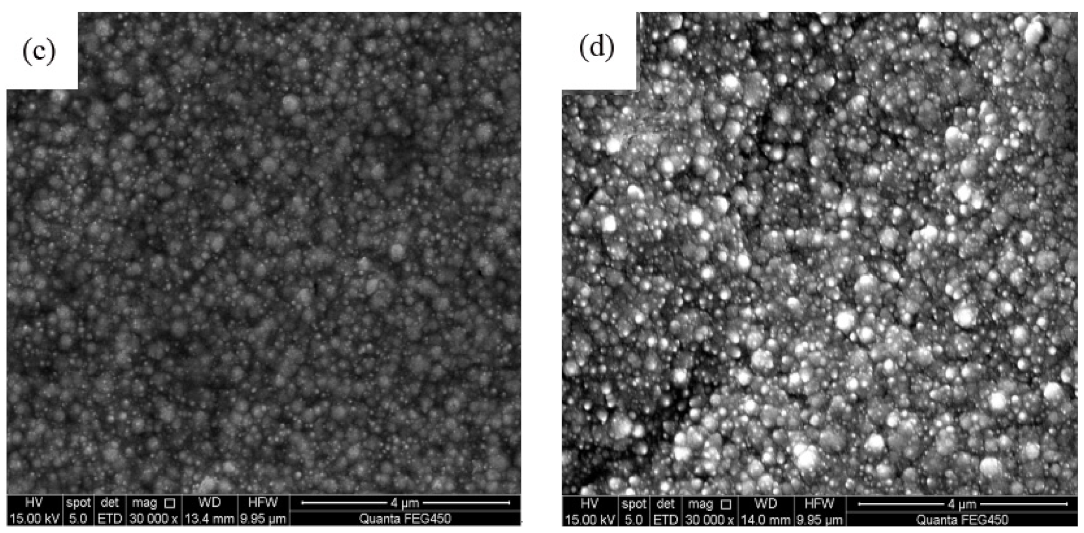
3.3. Survey of Phase Structure

Figure 5 shows XRD patterns of Ni–TiN CNCs manufactured at various nozzle diameters. SEM analyses discussed above indicated that the Ni crystal grains and TiN nanoparticles all existed in the composite coatings manufactured at diverse nozzle diameters, which signified that the nano-sized TiN particles and nickel crystal grains were fully embedded into the substrate. XRD patterns show that there is a decrease in diffraction intensity of the Ni–TiN CNCs (111) and (200) crystal planes as the spray nozzle diameter increases. The XRD peaks of the resulting Ni–TiN CNCs obtained at a Φ7 mm nozzle diameter became wider and less intense, which was nearly the same as the result obtained by Liu et al. [32]
The difference in crystallinity observed above is due to the different sized grains of Ni–TiN composite coatings deposited at different nozzle diameters. In addition, using Equation (1), we calculated the average sizes of nickel and TiN particles in the Ni–TiN CNCs produced at different nozzle diameters. The Φ3 mm nozzle diameter produced 453 and 236 nm sized grains of Ni and TiN respectively. The surface morphology of Ni–TiN CNCs produced at Φ3 mm nozzle diameter was the worst. The average sizes of nickel grain and TiN particles in the Ni–TiN CNCs prepared at the Φ7 mm nozzle diameter was 76 and 45 nm, respectively. The surface morphology of the Ni–TiN CNCs manufactured at Φ7 mm nozzle diameter appeared to be the best. However, the average sizes of nickel grain and TiN particles in the Ni–TiN CNCs fabricated at a Φ9 mm nozzle diameter were 146 and 91 nm, respectively. The average TiN particles sizes of the Ni–TiN CNCs were slightly larger than that of the initial added particles due to their agglomeration. The results are consistent with the study explicated by Zhang et al. [33].

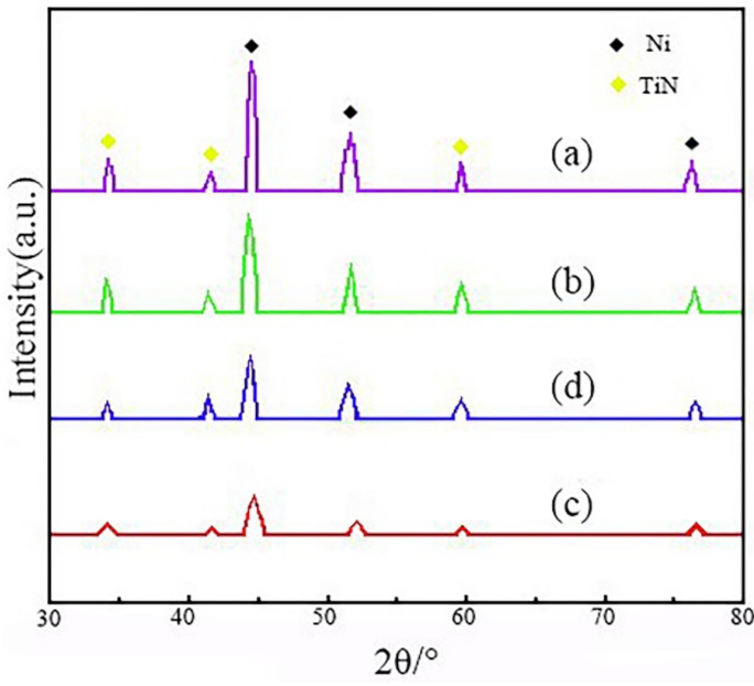
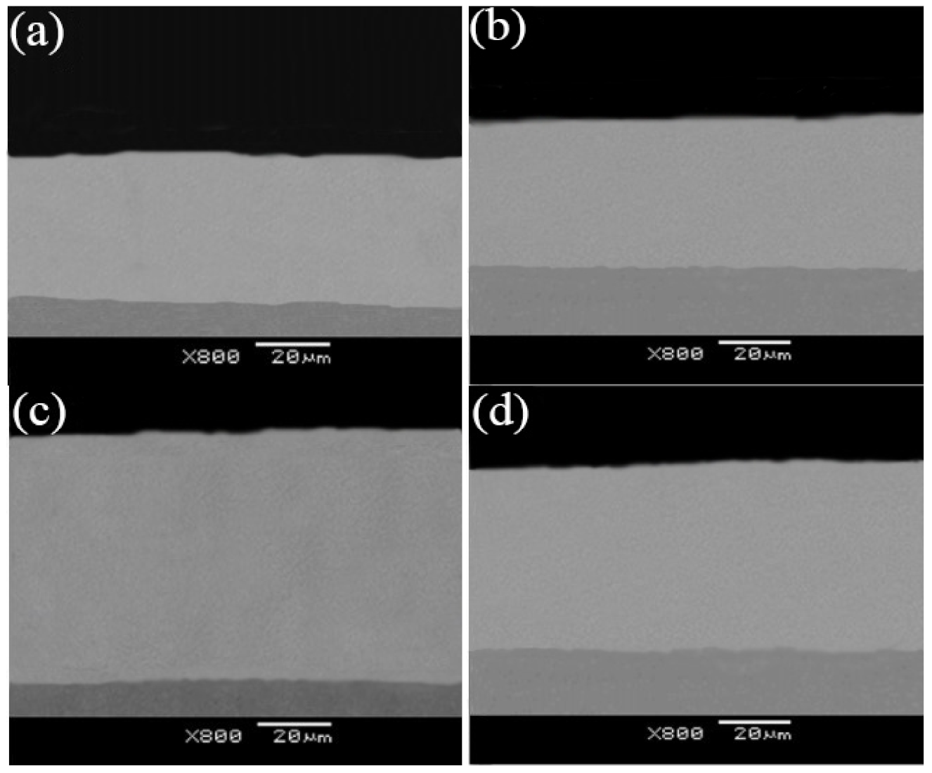
3.4. Abrasion Resistance

Figure 6 presents the fractography of Ni–TiN CNCs manufactured at various nozzle diameters. Figure 6a shows a rough fractography of the Ni–TiN CNCs produced at Φ3 mm nozzle diameters, which is due to the large pores and protrusions between the substrate and the composite coating, and the thin thickness of the coatings. The adhesion force between the substrate and the Ni–TiN CNCs produced at Φ3 mm nozzle diameters was 22.3 N. Figure 6b revealed that the pores, the protrusions, and the coating thickness between the substrate and the Ni–TiN CNCs prepared at Φ5 mm nozzle diameter was lower compared to that produced at the Φ3 mm nozzle diameter. Meanwhile, the coating thickness and adhesion forces between the substrate and the Ni–TiN CNCs produced at Φ5 mm nozzle diameter compared with that of Φ3 mm began to increase. Figure 6c revealed that uniform and compact fractography, little pores and protrusions, and the increased thickness of Ni–TiN CNCs was manufactured at Φ7 mm nozzle diameter. The adhesion force between the substrate and the Ni–TiN CNCs produced at Φ7 mm nozzle diameter was maximum at 198.2 N. Finally, Figure 6d presents the more uniform fractography and a slightly high thickness between the substrate and Ni–TiN CNCs fabricated at the Φ9 mm nozzle diameter compared to that of Φ3 and Φ5 mm. The adhesion force between the Ni–TiN CNCs produced at a Φ9 mm nozzle diameter and the substrate was 30.2 N.
These results indicate that the appropriate nozzle diameter produced an optimum spraying speed and spraying of the electrolyte. More of the uniformly nano-sized TiN particles were distributed in the Ni–TiN CNCs, which were deeper than the inlaying extent between the Ni–TiN CNCs and the substrate. The inlaying structure between the Ni–TiN CNCs and the substrate could tremendously reduce the generated pores and protrusions in the Ni–TiN CNCs and could enhance the adhesion force between the Ni–TiN CNCs and the substrate. In general, the lattice constant of the composite coatings was larger than that of the metal matrix. This is due to the atoms of the coating material interacting with the surface of the metal matrix during the JED process. The interaction between the atoms of the coating and the surface of the metal matrix resulted in an increasing adhesion force between the composite coating and the metal matrix. The phenomenon is consistent with the investigation stated by Jiang et al. [34] In addition, the different coefficient of thermal expansion between the Ni–TiN CNCs and the metal matrix led to the different adhesion surface, which resulted in a strong adhesion resistance ability when plastic deformation of composite coatings occurred.
Figure 7 displays the micro-hardness of Ni–TiN CNCs prepared at different nozzle diameters. It can be appreciated from the figure that the micro-hardness of Ni–TiN CNCs produced at the increasing nozzle diameters firstly increased and then decreased. The micro-hardness of Ni–TiN CNCs prepared at Φ3 mm nozzle diameter, calculated using Equation (2) was 468 Hv. The micro-hardness of the Ni–TiN CNCs further increased when the nozzle diameter was increased to Φ7 mm (647 Hv). However, the micro-hardness of Ni–TiN CNCs manufactured at Φ9 mm nozzle diameter was lower than that of Φ7 mm (493 Hv).
The reason behind the above experimental variation of micro-hardness is that the different nozzle diameters would impact the spraying pressure of the electrolyte, the growth rate and the deposition rate of coatings between the cathode and the anode when other process parameters were kept constant. The relatively high spraying pressure of the electrolyte due to the small nozzle diameter, but the excessive high spraying pressure of the electrolyte, was unevenly distributed across the whole specimen surface. The high and uneven spraying pressure of the electrolyte arrived at the cathode surface, leading to the different deposition rate and growth rate emerging in the various areas of Ni–TiN CNCs. With the growing nozzle diameter, the appropriate spraying pressure of the electrolyte lead to the growth rate and the deposition rate between the cathode and the anode being equal. Meanwhile, the micro-hardness of the Ni–TiN CNCs produced at the Φ7 mm nozzle diameter was maximum. The low spraying pressure of the electrolyte lead to a fast growth rate of coating, resulting in the decreased micro-hardness of the Ni–TiN CNCs manufactured at a Φ9 mm nozzle diameter.
Figure 8 displays the abrasion loss of Ni–TiN CNCs produced at various nozzle diameters. The data suggest that the abrasion loss of Ni–TiN CNCs produced at the increasing nozzle diameters first decreased and then increased. As calculated using Equations (3) and (4), the abrasion loss of the Ni–TiN CNCs prepared at the Φ3 mm nozzle diameter was 28.6 mg. The abrasion loss of the Ni–TiN CNCs decreased when the nozzle diameter increased from Φ3 mm to Φ7 mm. The abrasion loss of the Ni–TiN CNCs produced at a Φ7 mm nozzle diameter (17.3 mg) was obviously lower than that at other nozzle diameters. However, the abrasion loss of the Ni–TiN CNCs manufactured at a Φ9 mm nozzle diameter (20.1 mg) was larger than that at Φ7 mm.
The observed data could be explained considering the contact area between the electrolyte and the cathode when other process parameters were constant. The relatively fast spraying speed of the electrolyte due to the small nozzle diameter resulted in an uneven spraying speed of the electrolyte arriving at some area of the cathode. This lead to different contact points between the electrolyte and the cathode. With the increasing nozzle diameter, the appropriate spraying speed of the electrolyte leads to an even contact area between the electrolyte and the cathode. Further increasing the nozzle diameter leads to a lower spraying speed of the electrolyte, resulting in the decreased abrasion resistance of the Ni–TiN CNCs manufactured at a Φ9 mm nozzle diameter, due to the uneven contact area between the cathode and the electrolyte.
Figure 9 shows the frictional coefficient of the Ni–TiN CNCs prepared at various nozzle diameters. The size and distribution of nano-sized TiN particles in the coating surface determined the frictional coefficient of Ni–TiN CNCs. Note that the lower the frictional coefficient, the better the quality of the coating. The bigger size and smaller number of the TiN nanoparticles unevenly distributed across the coating surface led to a larger frictional coefficient of the Ni–TiN CNCs. The average frictional coefficient of the Ni–TiN CNCs prepared at Φ3 mm, Φ5 mm, Φ7 mm, and Φ9 mm nozzle diameters were 0.518, 0.437, 0.312, and 0.376, respectively. The frictional coefficient of the Ni–TiN CNCs prepared at Φ7 mm nozzle diameters was the lowest one, meaning that the coating quality was best.
This is again due to different sizes of nano-sized TiN particles in the Ni–TiN CNCs prepared at different nozzle diameters, which affects the friction and abrasion properties. The lower number of nano-sized TiN particles in the Ni–TiN CNCs were worse than the anti-attrition ability of composite coatings. The lower TiN particle content of Ni–TiN CNCs resulted in damage during the frictional process, where the abrasive grits harm the composite coatings. The exfoliated abrasive grits were continually accumulated on the surface of Ni–TiN CNCs, which resulted, in the end, in plastic deformation. Meanwhile, the plastic deformation increases the frictional coefficient of Ni–TiN CNCs, which results in a worse anti-attrition ability of the coating. The appropriate nozzle diameter generated a fine spraying speed and spraying pressure of the electrolyte, which further resulted in the abundant nano-sized TiN particles distributed uniformly. This resulted in a smooth and compact surface of Ni–TiN CNCs. The smooth and compact surface of Ni–TiN CNCs could act as a good lubricant role and could reduce the effect of adhesive abrasion during friction and wear testing.

4. Conclusions

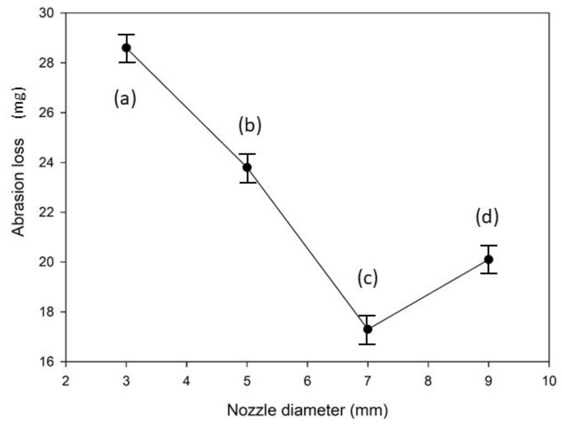
  • The spraying speed and spraying pressure of the electrolyte generated from a Φ7 mm nozzle diameter was optimum and produced Ni–TiN CNCs of the best quality. The Ni–TiN CNCs produced under these conditions contained a dense and smooth microstructure, containing a large number of TiN nanoparticles. The Ni–TiN CNCs manufactured at the too-small or too-large nozzle diameters were composed of an uneven surface, coarse crystal grains and a low TiN particle content.
  • The diffraction intensity of the (111) and (200) crystal planes of Ni–TiN CNCs prefabricated at a Φ7 mm nozzle diameter was lowest, which suggested that the crystal grains of Ni–TiN CNCs were smallest, with average diameters of nickel grains and TiN particles of 76 and 45 nm, respectively.
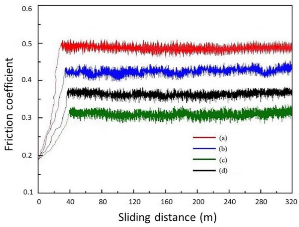
  • The diverse nozzle diameters used to fabricate the CNCs impacted their abrasion resistance. The micro-hardness and the adhesion force of the Ni–TiN CNCs prepared at a Φ7 mm nozzle diameter were the largest, at 647 Hv and 198.2 N, respectively. Meanwhile, the abrasion loss and the average frictional coefficient was 17.3 mg and 0.312, respectively, which meant that these CNCs possessed the best abrasion resistance among the fabricated coatings.

Author Contributions

Conceptualization and investigation, Z.Y.; writing—original draft preparation, S.Y.; writing—review, L.C.; writing—editing, S.T.; funding acquisition, Q.L. All authors have read and agreed to the published version of the manuscript.

Funding

This work has been supported by the Heilongjiang Postdoctoral Foundation of China (Granted No. LBH-Z20183), the Heilongjiang Bayi Agricultural University Support Program for San Heng San Zong (Granted Nos. TDJH201803 and TDJH202005), and the Scientific Research Starting Foundation for Returnees and Excellent Scholars (Granted No. XDB201804).

Institutional Review Board Statement

Not applicable.

Informed Consent Statement

Not applicable.

Data Availability Statement

Data is contained within the article.

Conflicts of Interest

The authors declare that they have no known competing financial interests or personal relationships that could have appeared to influence the work reported in this paper.

References

  1. Hashemi, S.H.; Ashrafi, A. Characterisations of low phosphorus electroless Ni and composite electroless Ni–P-SiC coatings on A356 aluminium alloy. Trans. IMF 2018, 96, 52–56. [Google Scholar] [CrossRef]
  2. Ma, C.; Yu, W.; Jiang, M.; Cui, W.; Xia, F. Jet pulse electrodeposition and characterization of Ni–AlN nanocoatings in presence of ultrasound. Ceram. Int. 2018, 44, 5163–5170. [Google Scholar] [CrossRef]
  3. Kaushal, S.; Gupta, D.; Bhowmick, H. On development and wear behavior of microwave-processed functionally graded Ni-SiC clads on SS-304 substrate. J. Mater. Eng. Perform. 2018, 27, 777–786. [Google Scholar] [CrossRef]
  4. Mousavi, R.; Bahrololoom, M.E.; Deflorian, F. Preparation, corrosion, and wear resistance of Ni–Mo/Al composite coating reinforced with Al particles. Mater. Des. 2016, 110, 456–465. [Google Scholar] [CrossRef]
  5. Sun, C.; Liu, X.; Zhou, C.; Wang, C.; Cao, H. Preparation and wear properties of magnetic assisted pulse electrodeposited Ni–SiC nanocoatings. Ceram. Int. 2018, 45, 1348–1355. [Google Scholar] [CrossRef]
  6. Ghosh Chaudhuri, R.G.; Paria, S. Core/Shell Nanoparticles: Classes, Properties, Synthesis Mechanisms, Characterization, and Applications. Chem. Rev. 2012, 112, 2373–2433. [Google Scholar] [CrossRef] [PubMed]
  7. Dai, J.; Liu, X.; Zhai, H.; Liu, Z.; Tian, J. Preparation of Ni-coated Si3N4 powders via electroless plating method. Ceram. Int. 2009, 35, 3407–3410. [Google Scholar] [CrossRef]
  8. Xu, X.; Zheng, Y.; Zhang, G.; Ke, Z.; Wu, H.; Yang, Z.; Zhou, W. Microstructure and mechanical properties of Ti(C,N)-based cermets fabricated using Ni–coated mixed powders. Ceram. Int. 2020, 46, 16944–16948. [Google Scholar] [CrossRef]
  9. Jiang, W.; Shen, L.; Xu, M.; Wang, Z.; Tian, Z. Mechanical properties and corrosion resistance of Ni–Co-SiC composite coatings by magnetic field-induced jet electrodeposition. J. Alloys Compd. 2019, 791, 847–855. [Google Scholar] [CrossRef]
  10. Ma, C.; Zhao, D.; Xia, F.; Xia, H.; Williams, T.; Xing, H. Ultrasonic-assisted electrodeposition of Ni-Al2O3 nanocomposites at various ultrasonic powers. Ceram. Int. 2020, 46, 6115–6123. [Google Scholar] [CrossRef]
  11. Xia, F.; Jiao, J.; Ma, C.; Wu, M. Forecast the microhardnesses of the Ni–TiN nanocoatings by AR model. Adv. Funct. Mater. 2012, 43, 140–143. [Google Scholar]
  12. Wang, C.; Li, K.; Huo, C.; He, Q.; Shi, X. Oxidation behavior and microstructural evolution of plasma sprayed La2O3-MoSi2-SiC coating on carbon/carbon composites. Surf. Coat. Technol. 2018, 348, 81–90. [Google Scholar] [CrossRef]
  13. Wasekar, N.P.; Bathini, L.; Sundararajan, G. Tribological behavior of pulsed electrodeposited Ni-W/SiC nanocomposites. J. Mater. Eng. Perform. 2018, 27, 5236–5245. [Google Scholar] [CrossRef]
  14. Yu, F.; Guo, H.; Cao, J.; Sun, C. Preparation and characterization of nickel-coated copper powder. Electroplat. Finish. 2011, 30, 21–23. (In Chinese) [Google Scholar]
  15. Ghaziof, S.; Gao, W. The effect of pulse electroplating on Zn-Ni alloy and Zn-Ni–Al2O3 composite coatings. J. Alloys Compd. 2015, 622, 918–924. [Google Scholar] [CrossRef]
  16. Wasekar, N.P.; Latha, S.M.; Ramakrishna, M.; Rao, D.S.; Sundararajan, G. Pulsed electrodeposition and mechanical properties of Ni-W/SiC nano-composite coatings. Mater. Des. 2016, 112, 140–150. [Google Scholar] [CrossRef]
  17. Wu, M.; Jia, W.; Lv, P. Electrodepositing Ni-TiN nanocomposite layers with applying action of ultrasonic waves. Procedia Eng. 2017, 174, 717–723. [Google Scholar] [CrossRef]
  18. Dehgahi, S.; Amini, R.; Alizadeh, M. Corrosion, passivation and wear behaviors of electrodeposited Ni–Al2O3–SiC nano-composite coatings. Surf. Coat. Technol. 2016, 304, 502–511. [Google Scholar] [CrossRef]
  19. Xia, F.; Li, C.; Ma, C.; Li, Q.; Xing, H. Effect of pulse current density on microstructure and wear property of Ni-TiN nanocoatings deposited via pulse electrodeposition. Appl. Surf. Sci. 2021, 538, 148139. [Google Scholar] [CrossRef]
  20. Li, X.; Feng, J.; Jiang, Y.; Lin, H.; Feng, J. Preparation and properties of TaSi2-MoSi2-ZrO2-borosilicate glass coating on porous SiC ceramic composites for thermal protection. Ceram. Int. 2018, 44, 19143–19150. [Google Scholar] [CrossRef]
  21. Xia, F.; Jia, W.; Ma, C.; Wang, J. Synthesis of Ni–TiN composites through ultrasonic pulse electrodeposition with excellent corrosion and wear resistance. Ceram. Int. 2018, 44, 766–773. [Google Scholar] [CrossRef]
  22. Ma, C.; Jiang, M.; Xia, F. Preparation and characterization of Ni–TiN thin films electrodeposited with nickel baths of different TiN nanoparticle concentration. Surf. Rev. Lett. 2016, 24, 17500631. [Google Scholar] [CrossRef]
  23. Li, B.; Zhang, W.; Zhang, W. Preparation of Ni–W/SiC nanocomposite coatings by electrochemical deposition. J. Alloys Compd. 2017, 702, 38–50. [Google Scholar] [CrossRef]
  24. Fan, H.; Liu, M.; Zhao, Y. The Al2O3 nano-particles influenced on morphology and microstructure of Cu-Al2O3 composite coating by jet electrodeposition. Key Eng. Mater. 2018, 764, 164–173. [Google Scholar] [CrossRef]
  25. Xia, F.; Jia, W.; Ma, C.; Yang, R.; Wang, Y.; Potts, M. Synthesis and characterization of Ni-doped TiN thin films deposited by jet electrodeposition. Appl. Surf. Sci. 2018, 434, 228–233. [Google Scholar] [CrossRef]
  26. Xia, F.; Jia, W.; Jiang, M.; Cui, W.; Wang, J. Microstructure and corrosion properties of Ni-TiN nanocoatings prepared by jet pulse electrodeposition. Ceram. Int. 2017, 43, 14623–14628. [Google Scholar] [CrossRef]
  27. Liu, W.; Jiang, K.; Li, Q.; Ma, C.; Xia, F. Jet pulse electrodeposited Ni–SiC thin coatings by using experimental system designed for potential industrial application. Int. J. Electrochem. Sci. 2021, 16, 21044. [Google Scholar] [CrossRef]
  28. Su, B.; Choy, K.L. Synthesis, microstructure and optical properties of ZnS films formed by electrostatic assisted aerosol jet deposition. J. Mater. Chem. 2000, 10, 949–952. [Google Scholar] [CrossRef]
  29. Xia, F.; Tian, J.; Wang, W.; He, Y. Effect of plating parameters on the properties of pulse electrodeposited Ni–TiN thin films. Ceram. Int. 2016, 42, 13268–13272. [Google Scholar] [CrossRef]
  30. Jiang, W.; Shen, L.; Qiu, M.; Wang, X.; Fan, M.; Tian, Z. Preparation of Ni-SiC composite coatings by magnetic field-enhanced jet electrodeposition. J. Alloys Compd. 2018, 762, 115–124. [Google Scholar] [CrossRef]
  31. Zhang, Z.; Du, Q. Study on magnetic field assisted electrodeposition of Ni–SiC nanocoatings on the surface of automobile cylinder liner. J. Funct. Mater. 2019, 50, 3081–3089. (In Chinese) [Google Scholar]
  32. Liu, H.; Wang, H.; Yu, W.; He, Y.; Xia, F.; Ma, C.; Shakoor, A. Effect of TiN concentration on microstructure and properties of Ni/W–TiN composites obtained by pulse current electrodeposition. Ceram. Int. 2021, 47, 24331–24339. [Google Scholar] [CrossRef]
  33. Zhang, H.; Wang, J.; Li, Q.; Chen, S.; Ma, C. Microstructure and performance of magnetic field assisted, pulse-electrodeposited Ni–TiN thin coatings with various TiN grain sizes. Ceram. Int. 2021, 47, 18532–18539. [Google Scholar] [CrossRef]
  34. Jiang, S.; Gao, S.; Kong, J.; Jin, X. Study on the synthesis of β-SiC nanoparticles from diamond-wire silicon cutting waste. RSC Adv. 2019, 9, 23785–23790. [Google Scholar] [CrossRef] [Green Version]
Figure 1. Schematics of the setup used for the jet electrodeposition process. 1—Pulse electrical source, 2—Electrolyte recovery, 3—Rotameter, 4—Servo system, 5—Nickel nozzle, 6—Specimen, 7—Platform, 8—Electrolytic cell, 9—Reciprocating pump.
Coatings 12 00086 g001
Figure 2. Simulation diagrams of the spraying speed of the electrolyte for preparing Ni–TiN coatings: (a,b) Nf = Φ3 mm, (c,d) Nf = Φ5 mm, (e,f) Nf = Φ7 mm, (g,h) Nf = Φ9 mm.
Coatings 12 00086 g002aCoatings 12 00086 g002b
Figure 3. Simulation diagram of the spraying pressure of the electrolyte for preparing Ni–TiN coatings: (a,b) Nf = Φ3 mm, (c,d) Nf = Φ5 mm, (e,f) Nf = Φ7 mm, (g,h) Nf = Φ9 mm.
Coatings 12 00086 g003aCoatings 12 00086 g003b
Figure 4. SEM graphs of Ni–TiN coatings deposited at diverse nozzle diameters: (a) Nf = Φ3 mm, (b) Nf = Φ5 mm, (c) Nf = Φ7 mm, (d) Nf = Φ9 mm.
Coatings 12 00086 g004aCoatings 12 00086 g004b
Figure 5. XRD patterns of Ni–TiN coatings deposited at disparate nozzle diameters: (a) Nf = Φ3 mm, (b) Nf = Φ5 mm, (c) Nf = Φ7 mm, (d) Nf = Φ9 mm.
Coatings 12 00086 g005
Figure 6. The fractography of Ni–TiN coatings deposited at different nozzle diameters: (a) Nf = Φ3 mm, (b) Nf = Φ5 mm, (c) Nf = Φ7 mm, (d) Nf = Φ9 mm.
Coatings 12 00086 g006
Figure 7. The micro-hardness of Ni–TiN coatings obtained at diverse nozzle diameters: (a) Nf = Φ3 mm, (b) Nf = Φ5 mm, (c) Nf = Φ7 mm, (d) Nf = Φ9 mm.
Coatings 12 00086 g007
Figure 8. The abrasion losses of Ni–TiN coatings prepared at different nozzle diameters: (a) Nf = Φ3 mm, (b) Nf = Φ5 mm, (c) Nf = Φ7 mm, (d) Nf = Φ9 mm.
Coatings 12 00086 g008
Figure 9. The frictional coefficient of Ni–TiN coatings prepared at various nozzle diameters: (a) Nf = Φ3 mm, (b) Nf = Φ5 mm, (c) Nf = Φ7 mm, (d) Nf = Φ9 mm.
Coatings 12 00086 g009
Table 1. Composition and parameters for prefabricating Ni–TiN coatings.
CompositionParameters
NiSO4·6H2O200 g/L
NiCl2·6H2O26 g/L
C3H6O4·6H2O3 g/L
TiN nanoparticles8 g/L
Saccharin sodium0.15 g/L
Cetyltrimethyl Ammonium Bromide (CTAB)0.05 g/L
Surfactant (Alkyl polyglycoside)150 mg/L
Temperature50 °C
pH4.3
Poles distance10 mm
Plating time50 min
Current density0.5 A/dm2
Publisher’s Note: MDPI stays neutral with regard to jurisdictional claims in published maps and institutional affiliations.

