Article

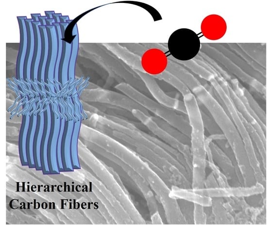
Hierarchical Porous Carbon Fibers Synthesized by Solution-Plasma-Generated Soot Deposition and Their CO2 Adsorption Capacity

by
Andres Eduardo Romero Valenzuela
1,
Chayanaphat Chokradjaroen
1,2,
Satita Thiangtham
1,2 and
Nagahiro Saito
1,3,4,5,*
1
Department of Chemical Systems Engineering, Graduate School of Engineering, Nagoya University, Furo-cho, Chikusa-ku, Nagoya 464-8603, Japan
2
Department of International Collaborative Program in Sustainable Materials and Technology for Industries between Nagoya University and Chulalongkorn University, Graduate School of Engineering, Nagoya University, Furo-cho, Chikusa-ku, Nagoya 464-8603, Japan
3
Japan Science and Technology Agency (JST), Strategic International Collaborative Research Program (SICORP), Furo-cho, Chikusa-ku, Nagoya 464-8603, Japan
4
Japan Science and Technology Agency (JST), Open Innovation Platform with Enterprises, Research Institute and Academia (OPERA), Furo-cho, Chikusa-ku, Nagoya 464-8603, Japan
5
Conjoint Research Laboratory in Nagoya University, Shinshu University, Furo-cho, Chikusa-ku, Nagoya 464-8603, Japan
*
Author to whom correspondence should be addressed.
Coatings 2022, 12(11), 1620; https://doi.org/10.3390/coatings12111620
Submission received: 30 September 2022 / Revised: 13 October 2022 / Accepted: 21 October 2022 / Published: 26 October 2022
(This article belongs to the Special Issue Science and Engineering of Coating)

Abstract

:
Global warming caused by CO2 emissions is a major environmental problem. Thus, the development of materials with innovative architectures that approach the CO2 problem is a necessity. In this study, hierarchical porous carbon fibers (HCFs) were synthesized by a chemical deposition process that operates at 400 °C and uses solution-plasma-generated soot (PGS) as a carbon precursor. Subsequently, the CO2 adsorption capacity of the synthesized material was evaluated. The HCFs showed enhanced surface areas and networks of micropores and mesopores. Moreover, the HCFs were post treated by metal etching and KOH activation. The post treated HCFs achieved a CO2 uptake of 0.8 mmol g−1 at 273 K, which was superior to the simultaneously produced solution plasma carbon (SPC), which has a CO2 uptake of 0.2 mmol g−1.

Graphical Abstract

1. Introduction

Carbon dioxide (CO2) greatly contributes to global warming and associated environmental problems. The temperature of the surface of the Earth increases by about 2.3 °C when the existing CO2 content of the atmosphere is doubled [1]. Therefore, it is of utmost importance to not only reduce emissions but also go beyond this by capturing and storing CO2. For several years, solid porous materials such as metal–organic frameworks [2,3], covalent organic frameworks [4,5], mesoporous silicas [6], porous polymers [7], and porous carbons [8,9,10,11] have been broadly investigated as adsorbents due to their advantages, which include large surface areas and high adsorption capacities. Among all solid porous materials, carbon materials have attracted interest for large-scale applications, owing to their affordability, ease of recovery and handling, and recyclability [10]. The fabrication process for porous carbon materials involves the pyrolysis of biomass or other organic precursors at more than 400 °C. Nearly all carbon materials contain pores, because they are products of thermal decomposition and their porosity is produced by the out-gassed components left behind during the carbonization process [9]. As a result, carbon materials have a broad pore size distribution which can be modulated by post chemical activation at high temperatures (700–1000 °C). Moreover, carbon materials have advantages such as high chemical stability, high temperature resistance, and low weight. Porous carbons have a broad pore size distribution that ranges from the micro to the macro scale. This hierarchical structure with mesopores and micropores is considered central for CO2 adsorption. Mesopores (50–52 nm) allow fast gas diffusion while micropores (less than 2 nm) induce high surface areas and adsorption dominated by interactions between the gas and the pore walls. Another feature of carbon materials is the different morphologies that they adopt. Fibrous activated carbons, especially with a hierarchical architecture, have major advantages over granular carbons in terms of porous structure and larger surface area, elements that are promising for CO2 adsorption [5,12,13,14,15,16].
Conventional methods for the fabrication of carbon fibers such as spinning and pyrolysis, are normally based on the precursors in use. The most common carbon fibers are polyacrylonitrile (PAN)-based fibers [17], pitch-based fibers [18], and vapor-grown fibers [8,19,20,21,22]. For the first two, the production method consists of spinning, stabilization, and carbonization. The spinning process can be difficult to handle and the carbonization process requires temperatures of more than 1000 °C [22]. On the other hand, vapor-grown fibers present the advantage of a rapid and simple synthesis, relative product uniformity, and a certain degree of graphitization. The nucleation of fibers follows the principle reported by Endo et al. [19,21], which describes the seeding of catalyst particles on a substrate. The contributing elements for the growth of fibers are: the substrate, the atmospheric composition and condition during the fiber growth, and the carbon precursor. Commonly, the carbon precursor is in a gaseous state such as acetylene, methane, carbon monoxide, etc., or in a liquid state such as benzene, ethanol, etc. Nevertheless, liquid precursors require means of conversion to gaseous form before reaching the active substrate; this requires a more complex setup with an external heating source and longer reaction durations for the growth of fibers.
Solution plasma (SP), an emerging plasma technology, has been developed for synthesizing a variety of materials, such as metal nanoparticles, metal oxides, and carbon materials with different structures [23,24,25,26]. By using organic solutions, carbon materials can be continuously generated. In SP, a non-equilibrium system emerges due to the large temperature gradient between the center of the plasma and the plasma–liquid interface [27,28]. This system generates activated particles such as ions, electrons, and radicals that interact with the surrounding solution, decomposing, re-arranging molecules, and giving rise to carbon materials. The advantages of this method include the use of different organic molecules as precursors containing different functional groups, fast synthesis rates, simple setup and operation at room temperature, and atmospheric pressure. It is important to mention that during the discharge and fast generation of carbon materials in solution, an organic vaporized product, so-called solution-plasma-generated soot (PGS), is simultaneously generated. Up to the present time, not much has been reported about the advantages and potential uses of this plasma-generated product.
Here, we demonstrate a method for synthesizing hierarchical structures consisting of vapor-grown hierarchical porous carbon fibers (HCFs), employing PGS as a precursor. The convergence of mechanisms that interact at multiple scales, especially from the meso and micro scale, are indispensable for adsorption purposes. Thus, CO2 adsorption is further explored in this work. Furthermore, post treatment procedures were applied to HCFs in order to modify the surface topography of the fibers and test their adsorption capacity for CO2. Moreover, the adsorption capacities and textural properties of simultaneously synthesized solution plasma carbon (SPC) were compared with those of the HCFs.

2. Materials and Methods

2.1. The Solution Plasma (SP) Reactor and Heating Chamber

The SP reactor setup consisted of a glass flask and two tungsten electrode rods (99.9% purity, Nilaco Corp., Tokyo, Japan) of 1.5 mm in diameter, with a gap of 1 mm between them. A solution of 80 mL of o-dichlorobenzene (99.0% purity, Kanto Chemical Co., Inc., Tokyo, Japan) was used as liquid precursor inside the SP reactor. Plasma was generated between the two electrodes using a high-voltage bipolar pulse generator (Pekuris AC-MV85-0002). The SP reactor was a closed system that included a bubbler (which dispensed the carrier gas) below the center of the plasma region and a single outlet in the center of the reactor’s superior cover (Figure 1a). A filter (SS304 mesh 100, 99.0% purity, Nilaco Corp.) was installed at the entrance of the outlet to avoid large particles of coalesced soot exiting the SP reactor. Moreover, a purge valve was installed to ensure the evacuation of air inside the SP reactor.
The SP reactor was connected to a heating chamber (modified furnace temperature max 2000 °C) by a gas dispenser tube with nozzles. The dispenser tube extended alongside the interior of a quartz tube (70 mm × 500 mm) inside the heating chamber. Reaction gases flowed inside the heating chamber at controlled flows using digital flowmeters. Argon gas (99.99%) was used as buffer gas and hydrogen gas (99.99%) as a co-catalyst gas. Both gas cylinders were purchased from Alpha System Co., Nagoya, Japan.

2.2. Synthesis of Hierarchical Carbon Fibers (HCF)

The contributing elements for the growth of fibers are: a nickel substrate (99.9% purity, Nilaco Corp.), a carbon precursor (PGS), and the atmospheric conditions during the fiber growth (temperature and flowing gases). Firstly, a nickel substrate (99.9% purity, Nilaco Corp.) with the size of 30 mm × 150 mm × 0.3 mm was washed with a 1 M HCl solution, rinsed with propanol, and loaded into the heating chamber for drying in a continuous flow of Ar. The chamber was heated at 900 °C under a 1:1 ratio of Ar:H2 atmosphere for 45 min to ensure the removal of impurities and the surface modification of the substrate. Next, the heating chamber temperature was reduced to a reaction temperature of 400 °C and held for 45 min before the deposition of the PGS.
In order to synthesize the PGS precursor, a volume of 80 mL of a pre-cooled solution of o-dichlorobenzene (5 ± 2 °C) was loaded inside the SP reactor. Before operating the SP reactor, Ar gas was bubbled to evacuate all the existing air for 1 min and the purge valve was then closed. The solution was stirred continuously during operation. The SP was generated between the two electrodes using a high-voltage bipolar pulse generator (Pekuris AC-MV85-0002). Subsequently, the outlet valve of SP reactor was opened and a plasma discharge was generated between the tungsten electrodes at 5 kV. The pulse repetition frequency and pulse duration were 80 kHz and 1.0 μs, respectively. The reaction time was kept for 9 min and the solution’s temperature was monitored every 3 min, reaching a maximum temperature of 38 ± 3 °C. The PGS was transported outside the SP reactor by a constant flow of Ar, which was carried and passed through the dispenser tube, reaching the Ni substrate at a temperature of 400 °C. Before deposition, the Ar supply inside the heating chamber was stopped in order not to vary the partial pressure once the Ar-carried PGS was inserted (ratio Ar:H2 inside the heating chamber remained unchanged). After 9 min, the plasma was stopped, the SP outlet valve was closed, and the cooling down of the substrate to room temperature was made under an Ar atmosphere. After that, the Ni substrate was removed from the heating chamber and the deposited carbon fibers were extracted from the substrate by sonication for 5 min in acetone. The HCFs were obtained from this step.
In addition, the simultaneously produced carbon material from the SP reactor was collected by filtration. This product was heat treated at 400 °C for 2 h under 1:1 Ar:H2 atmosphere. This sample was denominated as SPC.

2.3. HCF Post Treatment

The HCFs were post treated by KOH activation and metal etching, called HCF-K and HCH-E, respectively. For the preparation of HCF-K, 20 mg of HCFs were mixed with 30 mL of 2 M KOH and 20 mL of C2H5OH. The mixture suspension was sonicated for 10 min. Then, the sample was dried at 100 °C for 3 h. The collected product was loaded into a furnace and heated at 700 °C for 2 h under Ar atmosphere. The final product was washed with deionized water and dried for 8 h at 100 °C. For HCF-E, the Ni content was etched using an acid solution (20% HNO3, 8% H2SO4, 20% CH3COOH and 52% H2O). A total of 20 mg of HCFs were mixed with the acid solution, left to sit for 8 h, rinsed with distilled water, and then dried at 300 °C for 8 h.

2.4. Characterization

A field emission scanning electron microscope (FE-SEM, S-4800, Hitachi High-Technologies Co., Ltd., Tokyo, Japan) was used to observe the morphology of the carbon fibers with an acceleration voltage of 15 kV. The crystallinity was observed using X-ray diffraction equipment (XRD, Rigaku Co., Ltd., Smartlab, Tokyo, Japan) with monochromatic Cu Kα radiation (λ = 0.154 nm) operating at 45 kV and 200 mA. Raman analysis was measured by a spectrometer (Renishaw InVia TM Raman microscope) with a laser excitation wavelength of 532 nm. Specific surface area, pore volume, and average pore size of the carbon fibers were measured by the Brunauer–Emmett–Teller (BET) method, with N2 as adsorbent gas at liquid nitrogen temperature (77 K). The CO2 adsorption isotherms were measured with a BELSORP mini II analyzer (MicrotracBEL Corp) at 273 K and 298 K. Pore size distribution was analyzed by the software BELMASTER TM v 5.3.3.0, provided by BEL Japan Inc., Nagoya, Japan.
For the characterization of the physical properties of carbon materials and before any adsorption test, samples were loaded in a glass cell and pretreated under vacuum for 2 h at a temperature of 300 °C. Sample weight was measured precisely by comparing the blank glass cell weight (measured before pretreatment) and the glass cell weight with the sample after pretreatment.

3. Results

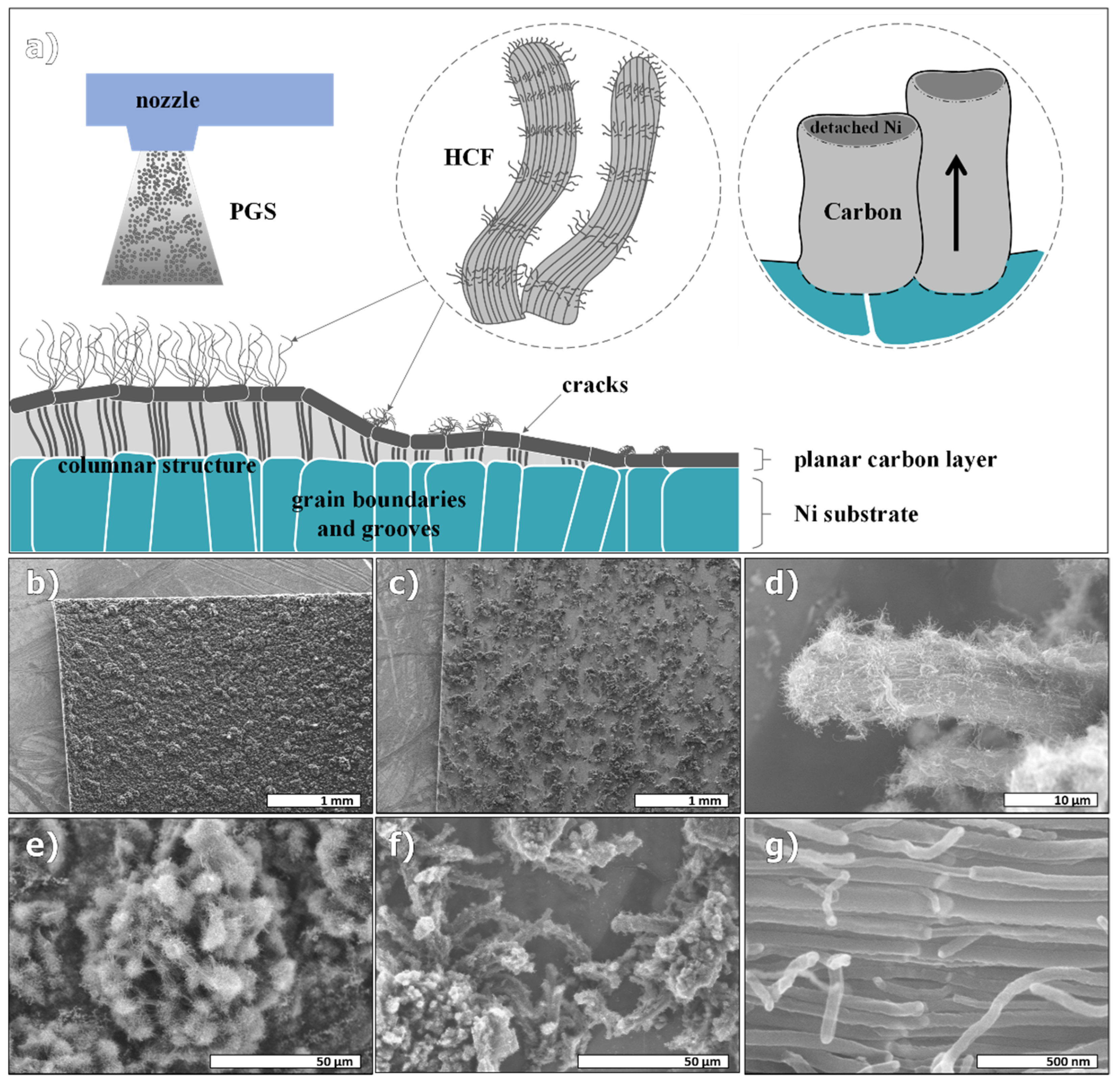
3.1. Hierarchical Structure

The scanning electron microscopy (SEM) images (Figure 2) of the substrate confirmed the presence of hierarchical carbon fibers (HCFs) grown by solution-plasma-generated soot (PGS) deposition. The gas dispenser inside the heating chamber allowed the continuous supply of precursor, allowing an extensive coverage of carbon material on the substrate. Figure 1a exhibits the formation of HCFs. Prior to the deposition process, the Ni substrate was thermally treated at 900 °C in a H2 and Ar atmosphere. This pretreatment not only removes impurities from the surface but also modifies the surface to be suitable for further nucleation of carbon fibers. The metal surface underwent some physical transformations even at a lower temperature than the melting point of nickel (1455 °C) [29]. The surface rearrangement after the annealing process consisted of the emergence of grooves; these were depressions that would act as sinks for precursor accumulation. These grooves were preserved when the substrate was cooled down to a fiber growth temperature of 400 °C. When the supply of PGS began, carbonaceous species of different molecular sizes accumulated on the surface to begin with the columnar growth of carbon. As reported by Bartholomew C., 1982 [30], in a range temperature between 200 and 500 °C, different carbon formations overlap on Ni, including carbides, amorphous carbon films and fibers, and graphitic carbons. Carbon was dissolved in nickel and adsorption energies on the surface varied according to the crystal orientation. Moreover, the binding of carbon atoms to grooves was stronger than on smooth planes. When hydrocarbons were adsorbed on the surface, carbon atoms/groups dissolved and migrated to growth centers, and after some deposition time, there was a separation or detachment of metal particles and the beginning of the columnar growth with nickel particles at the top. The nickel particles remained active during the growth, reaching the surface of the deposited material. Moreover, the use of o-dichlorobenzene as a carbon precursor in the SP reactor provided chlorine as a corrosion agent of the metal substrate; hence, if the substrate is rough, nickel particles are easily detached and fiber formation is favored. As seen in Figure 2b–e, SEM images show the nucleation of HCF clusters (comprising tightly grown fiber bundles) in a region where there was a major agglomeration of carbon precursor. The surface of the region under the distribution nozzle was densely covered by these kinds of clusters. Other regions of the substrate exposed to fewer amounts of precursor (Figure 2c,f) show how the fibers emerge from the grooves of the planar carbon layer. Additionally, Figure S1e,f (supporting information) shows a crack on the planar carbon layer from which the columnar architecture can be appreciated. Moreover, the emerging clusters of HCFs consist of bundles of individual and non-smooth carbon fibers with an average diameter of 167 ± 60 nm. (Figure 2d,f). Ni particles form part of the fiber’s structure at aligned segments perpendicular to the bundle’s growth axis (and parallel to the substrate). Furthermore, the nickel particles remain active during growth, providing new ramifications and prolonged growth (Figure S1b,d). These nodules can be seen along the fiber’s structure and can provide a shift in the fiber’s growth axis angle. Moreover, the alignment of the metallic segments in the bundles suggests the simultaneous detachment of nickel particles from the substrate surface and the emergence of the columnar architecture. The metal content of the fibers was estimated by Thermogravimetric Analysis (TGA) (Figure S2a), which shows 5% wt remaining after combustion at 1000 °C, corresponding to the metal content. Ni content provides magnetic properties to the collected material (Figure S2b).

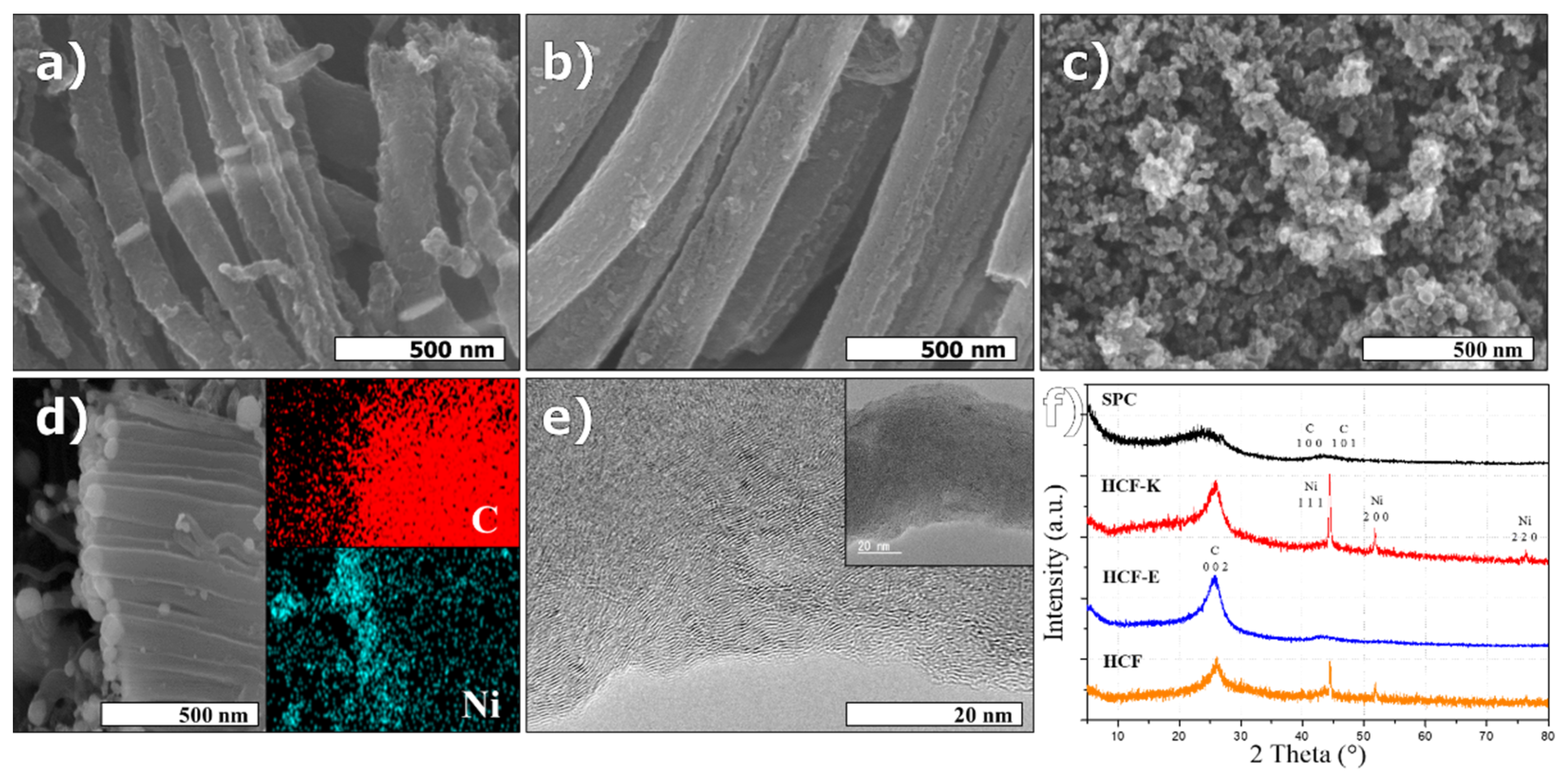
3.2. Post Modification of HCFs

The physical characteristics of the HCFs were altered with post modifications. As seen in the SEM images, the resulting HCF-K and HCF-E show different qualities to the non-treated HCFs. In HCF-K (Figure 3a), the characteristic bundles were unwrapped, and defects on the surfaces of the fibers are noticeable. Non-smooth surfaces have microporous sites that serve as sinks for adsorption or other reactions. By activating the HCFs it was possible to enhance microporosity by adding physical modifications, such as the unwrapping of the bundles of fibers and the introduction of surface defects on individual fibers in the form of rugosity and cavities (Figure S3a–f). Furthermore, the metal content was not removed from this sample, so the fibers did not lose their magnetic properties. Figure 3d shows an energy dispersive X-ray spectroscopy (EDX) image of a fiber bundle with nickel particles at the extremes.
Sample HCF-E was treated with an acid solution to remove the metal content and enhance the surface area. As seen in Figure 3b, the nickel segments are not perceivable along the individual fibers (See also Figure S2c,d). Moreover, bundles unwrapped and lost cohesion due to the removal of metal nodules that were keeping the fiber segments together. HCF-E also ceased to have magnetic properties due to the absence of nickel. As seen in the XRD patterns from the HCFs (Figure 3f), HCF-E, which lacks nickel content in its structure, shows a sharp peak at 25.89°, assigned to the carbon crystallographic plane (0 0 2). Moreover, the overlapping of carbon crystallographic planes (1 0 0) and (1 0 1) is perceivable at 43.31°. In contrast, activated HCF-K and plain HCF, which still preserved nickel content in their structure, show sharp peaks at 44.44°, 51.84° and 76.25° that correspond to the nickel crystallographic planes (1 1 1), (2 0 0), and (2 2 0), respectively. Other than these peaks, the corresponding carbon crystallographic planes at 25.97° (0 0 2) and ~43° (1 0 0) and (1 0 1) are observed for both samples. In addition, SPC shows a broad peak in the 19–26° range which is characteristic of amorphous carbon (Figure 3c). The ratio ID/IG of HCF is 0.55 compared to 0.82 of SPC by Raman analysis (Figure S4). Figure 3e shows a TEM micrograph of a fiber’s outer border in which carbon layers are turbostratic and stacked parallel to the fiber’s axis, and the stacking becomes random towards the center of the fiber. The interlayer spacing is 0.34 nm (Figure S5), which corresponds to the (0 0 2) plane of graphite. In fibers of a narrower diameter (around 20 nm), the orientation of the graphitic planes is more ordered and corresponds to a cup-like stacking. The interlayer spacing has a value of ~0.34 nm (Figure S5a). This result matches the XRD results for all of the HCFs. Additionally, the inset in Figure 3e shows the non-smooth surface of a fiber which is characteristic of all individual fibers in a bundle.

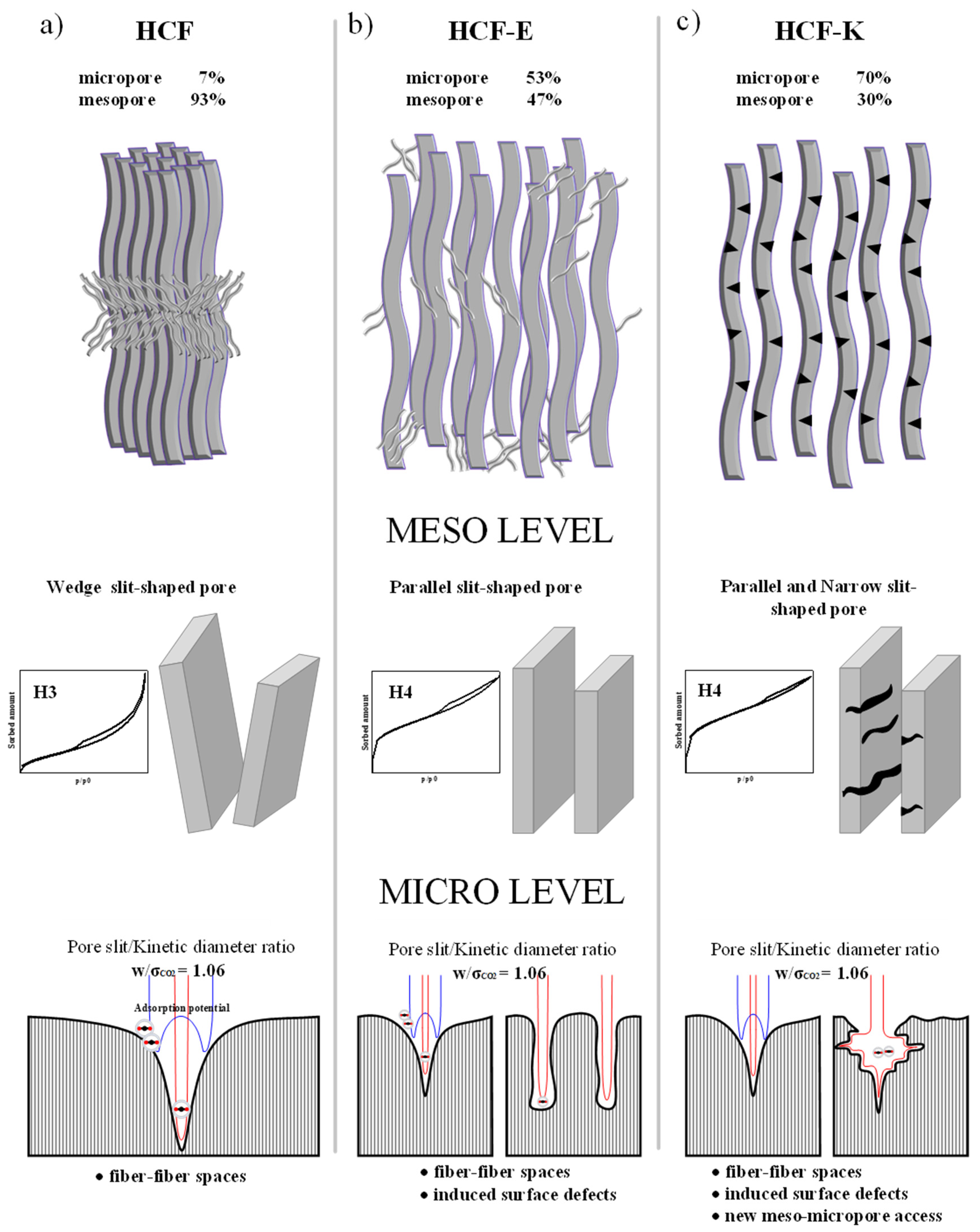
3.3. CO2 Adsorption of HCFs

In order to evaluate the physical characteristics for CO2 adsorption of the HCFs, N2 adsorption and desorption isotherms were measured and summarized in Figure 4 and Table 1. The pore size ranges from 0.7 to 20 nm in the HCFs, which indicates hierarchical porosities from mesopores to micropores (shown in Figure 3b). HCFs without any post modification were characterized by the presence of fibers tightly wrapped together as bundles. The average pore size of 7.693 nm indicates a dominant mesoporous structure, which is also confirmed by the type IV isotherm (Figure 4a). In terms of microporous structure, HCFs show a present but minor distribution even though the adsorption capacity for N2 gas is higher than for other materials. However, when HCFs were post treated there was a notable change in their textural properties. The Brunauer–Emmett–Teller (BET) surface areas of HCF-K and HCF-E are larger than those of plain HCFs. HCF-E showed the largest surface area of 379 m2 g−1 due to the physical modifications that the HCFs undergo after Ni etching. Microporosity was induced by removing the metallic parts of the fibers; bundles unwrapped and metallic nodules that gave continuity to fiber segments ceased to exist. The length of individual fibers was therefore reduced (Figure S2c,d). Interestingly, there was a noticeable increase in the micropore volume, from 0.027 to 0.171 cm3 g−1 and a reduction of the mesopore volume by about half, indicating that after nickel etching there was a collapse of the mesoporous structure and an increase in microporosity, providing a hierarchical network of micropores and mesopores. The adsorption–desorption isotherms for HCF-K and HCF-E correspond to a type IV isotherm with a steep inflection curve or knee, which indicates higher gas uptake by micropores at low partial pressures. Another noticeable characteristic is the hysteresis loop, typical for mesoporous materials. The desorption process is characterized by the presence of pore condensation in mesopores, where adsorption depends not only on fluid–wall interactions but also, fluid–fluid interactions that produce condensation in the pores. The gradual desorption is also the result of different pore interactions associated with pore evaporation between connected structures in the hierarchical network. In the case of HCF-K, there was also an increase in the surface area and micropore volume, and a marked reduction of the mesopore volume. This sample was activated with KOH at 700 °C, which induced surface defects and cavities on the surface of individual fibers (Figure S3). The increase in micropore volume could be associated with the emergence of such surface defects and cavities on the fibers. At the same time, the fiber bundles were unwrapped and the mesoporous network collapsed. It should be noted that the post treatment processes (i.e., prolonged sonication and heat treatment) induce the collapse of brittle structures and raise the amounts of the amorphous phase which might influence the changes in surface area. In the case of SPC, the surface area and pore volumes are inferior to that for any other HCFs synthesized simultaneously inside the SP reactor. The adsorption–desorption at liquid N2 temperature shows a type II isotherm, corresponding to a non-porous or macroporous adsorbent. Likewise, the physical properties of the soot, denominated ST, are detailed in Table 1 and Figure S6b. This product that was collected from the heating chamber (soot that did not nucleate on the Ni substrate and coalesced), showed even less surface area than both HCFs and SPC. SEM images of the non-nucleated and coalesced soot can be seen in Figure S6.
CO2 adsorption measurements were performed at 273 K and 298 K from 0 to 1 bar. Figure 4c,d displays the CO2 adsorption isotherms of HCFs and SPC and their adsorption capacities, as listed in Table 1. HCFs exhibited a superior adsorption capacity to post modified HCF-K and HCF-E at 298 K. HCFs had a dominant mesoporous structure with tightly bundled longer fibers, which influenced the adsorption of CO2. HCF-E and HCF-K are outperformed despite their enhanced micropore volume. This situation might be explained by the collapse of the mesoporous structure during post treatment, which created amorphous carbon segments that were not active sites for CO2 adsorption. SPC, which was predominantly amorphous carbon, presented the lowest adsorption capacity among all the materials.
Measurements at 273 K showed an increase in the adsorption capacity of CO2 for all HCFs. HCFs demonstrated an increase in adsorption capacity, from 0.485 to 0.818 mmol g−1. At the same time, HCF-E matched HCFs by adsorbing 0.8 mmol g−1. This increase in adsorption capacity could be attributed to the enhanced textural properties such as a larger micropore volume and surface area. At lower temperatures, CO2 had a better interaction with the hierarchical structure of HCF-E. HCF-K also demonstrated an increased CO2 adsorption capacity at a lower temperature. In contrast, the adsorption capacity of SPC CO2 remained almost unchanged with temperature. The isosteric heats of adsorption Qst of the HCF and SPC were calculated from the adsorption isotherms at 273 K and 298 K using the Clausius-Clapeyron equation. The isosteric heats vary from −0.5 kJ mo−1 to 6 kJ mol−1 (Figure S7).

4. Discussion

4.1. Hierarchical Structure

Carbon materials with a defined morphology and a network consisting of heterogeneous and interconnected pores favor the adsorption of CO2. However, synthesizing a material that has all these features is challenging and requires complex methods of production. SP is an emerging method for carbon material synthesis due to its evident advantages, such as fast synthesis and the use of a simple setup that operates under mild conditions of temperature and pressure. Nevertheless, having control over the morphology remains challenging [28]. In this study, we engineered a way to combine all the features of the SP process to provide a hierarchical material with defined features in the macro, meso and micro scales.
It is important to mention that the hierarchical structure of the final product has a direct relation with the method of supplying the carbon precursor, and SP provides an adequate pathway for such an endeavor. Firstly, the inception of PGS occurs under mild conditions (room temperature and atmospheric pressure). Contrary to thermal decomposition systems in which high operation temperatures are required, SP operates at room temperature and atmospheric pressure. Secondly, SP has the advantage of using liquid raw materials, which are easier to handle than precursors in gas states. With this approach it is possible to select a pure solution or a mixture in order to produce a final product with a particular functionality and composition. In our case, the selection of o-dichlorobenzene was of great importance for providing a final hierarchical material. The presence of chlorine, which works as a strong oxidation agent, promotes corrosion and defect formation on the surface of the Ni substrate where the growth of fibers takes place [31,32]. To test this, the PGS from different precursors was utilized for carbon growth and the morphological characteristics were analyzed (Figure S8). The hierarchical structure only corresponded to the fibers grown by the PGS generated by o-dichlorobenzene. Additionally, the existence of surface defects was found to play an important role in the nucleation and growth of columnar structures due to the surface softening effects provided by the precursor’s composition and the conditions inside the reactor. The columnar growth happened at relatively low temperatures of 400 °C in the presence of hydrogen, which acted as a co-catalyst for the growth of fibers. A hydrogen atmosphere contributed to the dehydrogenation and activation of hydrocarbons [33]. Moreover, by softening the metal surface it was possible to generate longer and uniform fibers due to the detachment of nickel particles. Such particles are of crucial importance for the growth of fibers, since their size determines the diameter of an individual fiber. Furthermore, the detached Ni particles, kept active during growth, generated more seeds for fiber nucleation and contributed to the hierarchical structure. All ramifications along the fiber bundle originated from the still-active Ni metal particles. SEM images confirmed the presence of Ni nodules along the growth axis, providing segments that became brittle if the metal was etched. Metal particles provided structural support to the bundle architecture. It is also worth mentioning that the metal content added magnetic properties to the fibers, a property that needs to be explored further for other applications. TEM imaging confirmed the turbostratic orientation of graphitic layers in the fiber’s borders, providing a crystalline structure. Thinner fibers (<100 nm) showed even more ordered orientations in their structure (Figure S5a). XRD and Raman results (Figure 3f and Figure S4, respectively), confirmed the superiority of the HCFs in comparison to the SPC in terms of crystallinity. When the fibers were activated with KOH and a reaction temperature of 700 °C (HCF-K), cavities were introduced perpendicular to the growth axis. These fibers, which had a lamellar structure, demonstrated additional adsorption sites and enhanced microporosity (Figure S3). Finally, the HCFs synthesized by this method presented better properties in terms of adsorption and crystallinity compared to the simultaneously synthesized carbon material inside the SP reactor.

4.2. Morphology and CO2 Adsorption Synergy

The HCFs had a dominant mesoporous structure consisting of long fibers (some reaching ~130 μm), tightly bundled together (Figure 5 and Figure S1). The bundles were tightly wrapped and micropores were secluded in inter-fiber spaces. The adsorption–desorption isotherm shows a hysteresis loop type H3, characteristic of mesoporous materials with slit-shaped pores. In the desorption process, H3 shows a steep region or “knee” that closes the hysteresis loop, due to the tensile strength effect [34]. In the case of HCFs, access to micropores could be found in the narrow spaces between neighboring fibers that extended across the bundle’s length, and the adsorption of CO2 was favored in these spaces where the adsorption potentials overlapped. Although the HCFs showed a dominant mesoporous structure, this did not exclude the presence of micropores along the bundles and between ramifications. When the metal content that provided cohesion to the bundle was removed (HCF-E), there was a clear increase in the surface area and microporosity. Fibers that detached and kept their integrity contributed with more active sites for adsorption. The hysteresis loop shown in the desorption cycle corresponds to the type H4 [35], referring to narrow slit pores, excluding those of the microporous region at lower partial pressures. The unwrapping of the fiber bundles allowed major access to microporous sites that included fiber–fiber spaces, and also induced defects caused by the post treatment with acid. These defects acted as adsorption sites. Moreover, when the metal was removed, there was a fracture of fibers in the locations where the Ni nodules were etched, yielding shorter fibers and enhanced microporosity due to the new fiber–fiber space contacts. HCF-E had a higher adsorption capacity due to its superior microporous sites, which matched the size of the adsorbed molecule. The critical parameter was not the pore size itself (the width of the slit), but rather the ratio of w/σ CO2 (half width of the slit/molecule kinetic diameter of CO2, 0.33 nm) [36]. As the slit width diminishes, the interaction potential (energy) merges to give a single minimum [34]. In the case of all synthesized HCFs, their pore size distribution shows the existence of micropores of 0.7 nm (Figure 4b), which means that the ratio w/σ is close to 1, point where the adsorption potential overlaps due to wall–fluid interactions. Nevertheless, the proportion of such sites fluctuates in HCF-E and HCF-K. The latter had a superior micropore proportion due to the enhanced induction of defects on single fibers, creating lamellar structures. Furthermore, post treatment contributed to increased amounts of amorphous carbon; carbon structures that were not crystalline enough collapsed and contributed to the amorphous proportion. For this reason, HCF-K showed an inferior adsorption capacity compared to the other HCFs. The superior microporosity of HCF-K could be attributed to the lamellar structure of the fibers. However, the separation of this type of fiber has not been attempted in the present work, and the textural properties corresponded to the overall product which was a mixture of amorphous and crystalline portions. Nevertheless, the CO2 adsorption of this sample took place in such microporous spaces. Finally, the morphological and textural properties of SPC were inferior to any of the HCFs. Amorphous carbon, in granular coalesced morphologies (Figure 3c), showed lower adsorption capacities for CO2 even after thermal treatment and activation.

5. Conclusions

Here, we reported for the first time the usage of solution-plasma-generated soot (PGS) as a precursor for the growth of hierarchical carbon structures with a defined fibrous morphology. The synergistic factors that govern the nucleation of fibers were linked to the method in which the precursor was supplied to the deposition system for the growth of HCFs. The HCFs showed better crystallinity, hierarchical networks with micro and mesopores, magnetic properties, and larger surface areas compared to the simultaneously synthesized SPC. CO2 adsorption was conducted, and the results showed larger adsorption capacities for HCFs, reaching 0.81 mmol g−1. By applying post treatment processes on the fibers, it was possible to generate additional active sites for CO2 adsorption. HCF-K showed a lamellar structure (Figure S3) that requires further investigation for adsorption purposes.

Supplementary Materials

The following supporting information can be downloaded at: https://www.mdpi.com/article/10.3390/coatings12111620/s1, Figure S1: HCF bundles. Figure S2: Thermogravimetric analysis (TGA) and metal content. Figure S3: HCF-K Surface defects on individual fibers and cavities (lamellar structure). Figure S4: Raman analysis. Figure S5: Turbostratic growth of fibers. Figure S6: Soot characterization (ST). Figure S7: Isosteric heats of adsorption. Figure S8: Carbon fibers grown with different PGS.

Author Contributions

Conceptualization, A.E.R.V. and C.C.; methodology, A.E.R.V. and C.C.; software, A.E.R.V.; validation, A.E.R.V., C.C., S.T. and N.S.; formal analysis, A.E.R.V.; investigation, A.E.R.V.; resources, A.E.R.V., C.C., S.T. and N.S.; data curation, A.E.R.V., C.C. and S.T.; writing—original draft preparation, A.E.R.V.; writing—review and editing, A.E.R.V., C.C. and S.T.; visualization, A.E.R.V.; supervision, C.C. and N.S.; project administration, A.E.R.V. and C.C.; funding acquisition, N.S. All authors have read and agreed to the published version of the manuscript.

Funding

This research was funded by the Open innovation platform with enterprises, research institute and academia (OPERA), grant number JPMJOP1843 and Strategic international collaborative research program (SICORP), grant number JPMJSC18H1.

Institutional Review Board Statement

Not applicable.

Informed Consent Statement

Not applicable.

Data Availability Statement

Not applicable.

Acknowledgments

Ministry of Education, culture, sports, science and technology—Japan (MEXT) scholarship.

Conflicts of Interest

The authors declare no conflict of interest.

References

  1. Manabe, S. Modeling Study of Greenhouse Warming—A Citation-Classic Commentary on Thermal-Equilibrium of the Atmosphere with a Given Distribution of Relative-Humidity by Manabe, S. and Wetherald, R.T. Cc/Eng. Technol. Appl. Sci. 1993, 8, 8. [Google Scholar]
  2. Yaghi, O.M. Reticular Chemistry in All Dimensions. ACS Central Sci. 2019, 5, 1295–1300. [Google Scholar] [CrossRef] [Green Version]
  3. Lyu, H.; Li, H.; Hanikel, N.; Wang, K.; Yaghi, O.M. Covalent Organic Frameworks for Carbon Dioxide Capture from Air. J. Am. Chem. Soc. 2022, 144, 12989–12995. [Google Scholar] [CrossRef]
  4. Li, J.; Zhao, D.; Liu, J.; Liu, A.; Ma, D. Covalent Organic Frameworks: A Promising Materials Platform for Photocatalytic CO2 Reductions. Molecules 2020, 25, 2425. [Google Scholar] [CrossRef] [PubMed]
  5. Zhao, S.; Dong, B.; Ge, R.; Wang, C.; Song, X.; Ma, W.; Wang, Y.; Hao, C.; Guo, X.; Gao, Y. Channel-wall functionalization in covalent organic frameworks for the enhancement of CO2 uptake and CO2/N2 selectivity. RSC Adv. 2016, 6, 38774–38781. [Google Scholar] [CrossRef]
  6. Kuroda, K. Discovery of mesoporous silica from layered silicates. In Studies in Surface Science and Catalysis; Terasaki, O., Ed.; Elsevier: Amsterdam, The Netherlands, 2004; Volume 148, pp. 73–108. [Google Scholar]
  7. Lee, J.-S.M.; Cooper, A.I. Advances in Conjugated Microporous Polymers. Chem. Rev. 2020, 120, 2171–2214. [Google Scholar] [CrossRef] [Green Version]
  8. Inagaki, M. Chapter 6—Intercalation compounds New Carbons—Control of Structure and Functions; Inagaki, M., Ed.; Elsevier Science: Amsterdam, The Netherlands, 2000; pp. 146–176. [Google Scholar]
  9. Inagaki, M. Chapter 5—Porous carbons New Carbons—Control of Structure and Functions; Inagaki, M., Ed.; Elsevier Science: Amsterdam, The Netherlands, 2000; pp. 124–145. [Google Scholar]
  10. Siegelman, R.L.; Kim, E.J.; Long, J.R. Porous materials for carbon dioxide separations. Nat. Mater. 2021, 20, 1060–1072. [Google Scholar] [CrossRef] [PubMed]
  11. Ma, D.; Li, J.; Liu, A.; Chen, C. Carbon Gels-Modified TiO2: Promising Materials for Photocatalysis Applications. Materials 2020, 13, 1734. [Google Scholar] [CrossRef] [Green Version]
  12. Ma, X.; Li, Y.; Cao, M.; Hu, C. A novel activating strategy to achieve highly porous carbon monoliths for CO2 capture. J. Mater. Chem. A 2014, 2, 4819–4826. [Google Scholar] [CrossRef]
  13. Srinivas, G.; Krungleviciute, V.; Guo, Z.-X.; Yildirim, T. Exceptional CO2 capture in a hierarchically porous carbon with simultaneous high surface area and pore volume. Energy Environ. Sci. 2013, 7, 335–342. [Google Scholar] [CrossRef] [Green Version]
  14. Tian, W.; Zhang, H.; Sun, H.; Suvorova, A.; Saunders, M.; Tade, M.; Wang, S. Heteroatom (N or N-S)-Doping Induced Layered and Honeycomb Microstructures of Porous Carbons for CO Capture and Energy Applications. Adv. Funct. Mater. 2016, 26, 8651–8661. [Google Scholar] [CrossRef]
  15. Singh, S.K.; Akhtar, M.J.; Kar, K.K. Hierarchical Carbon Nanotube-Coated Carbon Fiber: Ultra Lightweight, Thin, and Highly Efficient Microwave Absorber. ACS Appl. Mater. Interfaces 2018, 10, 24816–24828. [Google Scholar] [CrossRef] [PubMed]
  16. Wang, H.; Xu, C.; Zhou, Y.; Zhao, W.; Zhong, J.; Huang, W.; Chen, R. Fabrication of Hierarchical N-doped Carbon Nanotubes for CO2 Adsorption. Nano 2019, 14, 1950072. [Google Scholar] [CrossRef]
  17. Zhou, Z.; Liu, T.; Khan, A.U.; Liu, G. Block copolymer–based porous carbon fibers. Sci. Adv. 2019, 5, eaau6852. [Google Scholar] [CrossRef] [Green Version]
  18. Smith, G.W.; White, J.L.; Buechler, M. Mesophase/isotropic phase interfacial energy: Determination from coalescence kinetics of mesophase pitch. Carbon 1985, 23, 117–121. [Google Scholar] [CrossRef]
  19. Endo, M.; Koyama, T.; Hishiyama, Y. Structural Improvement of Carbon Fibers Prepared from Benzene. Jpn. J. Appl. Phys. 1976, 15, 2073–2076. [Google Scholar] [CrossRef]
  20. Oberlin, A.; Endo, M.; Koyama, T. Filamentous growth of carbon through benzene decomposition. J. Cryst. Growth 1976, 32, 335–349. [Google Scholar] [CrossRef]
  21. Endo, M.; Kroto, H.W. Formation of carbon nanofibers. J. Phys. Chem. 1992, 96, 6941–6944. [Google Scholar] [CrossRef]
  22. Inagaki, M. Chapter 4—Carbon Fibers New Carbons—Control of Structure and Functions; Inagaki, M., Ed.; Elsevier Science: Amsterdam, The Netherlands, 2000; pp. 82–123. [Google Scholar]
  23. Kang, J.; Li, O.L.; Saito, N. Synthesis of structure-controlled carbon nano spheres by solution plasma process. Carbon 2013, 60, 292–298. [Google Scholar] [CrossRef]
  24. Hyun, K.; Saito, N. The solution plasma process for heteroatom-carbon nanosheets: The role of precursors. Sci. Rep. 2017, 7, 3825. [Google Scholar] [CrossRef] [Green Version]
  25. Chae, S.; Panomsuwan, G.; Bratescu, M.A.; Teshima, K.; Saito, N. p-Type Doping of Graphene with Cationic Nitrogen. ACS Appl. Nano Mater. 2019, 2, 1350–1355. [Google Scholar] [CrossRef]
  26. Kim, K.; Chokradjaroen, C.; Saito, N. Solution plasma: New synthesis method of N-doped carbon dots as ultra-sensitive fluorescence detector for 2,4,6-trinitrophenol. Nano Express 2020, 1, 020043. [Google Scholar] [CrossRef]
  27. Saito, N.; Hieda, J.; Takai, O. Synthesis process of gold nanoparticles in solution plasma. Thin Solid Films 2009, 518, 912–917. [Google Scholar] [CrossRef]
  28. Morishita, T.; Ueno, T.; Panomsuwan, G.; Hieda, J.; Yoshida, A.; Bratescu, M.A.; Saito, N. Fastest Formation Routes of Nanocarbons in Solution Plasma Processes. Sci. Rep. 2016, 6, 36880. [Google Scholar] [CrossRef] [Green Version]
  29. Pakhnevich, A.A.; Golod, S.V.; Prinz, V.Y. Surface melting of copper during graphene growth by chemical vapour deposition. J. Phys. D Appl. Phys. 2015, 48, 435303. [Google Scholar] [CrossRef]
  30. Bartholomew, C.H. Carbon Deposition in Steam Reforming and Methanation. Catal. Rev. 1982, 24, 67–112. [Google Scholar] [CrossRef]
  31. Hayashi, T.; Karita, M.; Nakano, T.; Inoue, Y. A study on the growth enhancement effects of chlorine on carbon nanotube forest in chloride-mediated chemical vapor deposition. Jpn. J. Appl. Phys. 2021, 60, 045001. [Google Scholar] [CrossRef]
  32. Schmidt, I.; Benndorf, C. Using fluorine and chlorine in the diamond CVD process. Diam. Relat. Mater. 1999, 8, 231–235. [Google Scholar] [CrossRef]
  33. Vlassiouk, I.; Regmi, M.; Fulvio, P.; Dai, S.; Datskos, P.; Eres, G.; Smirnov, S. Role of Hydrogen in Chemical Vapor Deposition Growth of Large Single-Crystal Graphene. ACS Nano 2011, 5, 6069–6076. [Google Scholar] [CrossRef]
  34. Eddaoudi, M. Characterization of Porous Solids and Powders: Surface Area, Pore Size and Density By S. Lowell (Quantachrome Instruments, Boynton Beach), J.E. Shields (C. W. Post Campus of Long Island University), M.A. Thomas, and M. Thommes (Quantachrome In-struments). Kluwer Academic Publishers: Dordrecht, The Netherlands. 2004. xiv + 348 pp. $159.00. ISBN 1-4020-2302-2. J. Am. Chem. Soc. 2005, 127, 14117. [Google Scholar] [CrossRef]
  35. Haul, R.S.J.; Gregg, K.S.W. Sing: Adsorption, Surface Area and Porosity. 2. Auflage, Academic Press, London 1982. 303 Seiten, Preis: $ 49.50. Ber. Bunsenges. Phys. Chem. 1982, 86, 957. [Google Scholar] [CrossRef]
  36. Cui, X.; Bustin, R.; Dipple, G. Selective transport of CO2, CH4, and N2 in coals: Insights from modeling of experimental gas adsorption data. Fuel 2004, 83, 293–303. [Google Scholar] [CrossRef]
Figure 1. (a) Experimental setup consisting of the solution plasma reactor and the heating chamber connected by a gas dispenser system. (b) Hierarchical carbon fiber growth and surface modification. Solution plasma was used as the method for supplying the carbon precursor (PGS) and subsequent fiber growth on a Ni substrate. Then, the surface of the fibers was modified to enhance their physical properties for CO2 adsorption.
Coatings 12 01620 g001
Figure 2. Images of the HCFs grown on a Ni substrate. (a) Sketch of the formation of HCFs across different regions of the substrate. (b,e) HCFs grown under the nozzle where there is a major accumulation of precursor. (c,f) Region of the substrate where there is less concentration of precursor, characterized by the emerging fiber bundles from cracks and grooves on the planar carbon layer. (d,g) Bundle of HCFs comprising non-smooth fibers of relative regular diameters. Segments with ending metal particles can be observed across the growth axis.
Coatings 12 01620 g002
Figure 3. HCFs after modification. (a) HCF-K after activation with KOH. Segments of the fibers present Ni metal nodules (brighter segments of the fiber). (b) HCFs after Ni etching with acid (HCF-E). The HCF bundles unwrapped and metal nodules are not perceived. (c) Carbon material obtained inside the SP reactor (o-dichlorobenzene as precursor). (d) EDX of the fibers showing the Ni particles at the extremes of the fibers. (e) TEM micrograph of the outer border of a carbon fiber. (f) XRD pattern of post-treated HCFs and solution plasma carbon (SPC), also post treated at 400 °C under Ar and H2 atmosphere.
Coatings 12 01620 g003
Figure 4. Textural properties of HCFs and CO2 adsorption. (a) N2 adsorption–desorption isotherms at liquid nitrogen temperature (77 K). (b) Pore size distribution extracted from t-plot for microporosity and BJH desorption for mesoporous pore distribution (inset). (c) CO2 adsorption isotherms at 298 K. (d) and 273 K.
Coatings 12 01620 g004
Figure 5. Morphological and CO2 adsorption synergy of (a) HCFs, (b) HCF-E and (c) HCF-K.
Coatings 12 01620 g005
Table 1. Physical characteristics of the carbon samples.
SampleSBET
(m2 g−1) (a)
VT (cm3 g−1) (a)Vmic (cm3 g−1) (b)Vmeso (cm3 g−1) (c)Average Pore Size (nm) (a)CO2 Adsorption at 273 K
(mmol g−1)
CO2 Adsorption at 298 K
(mmol g−1)
HCFs2110.4060.0270.3797.6930.8180.485
HCF-K2790.1820.1280.0542.6190.4960.311
HCF-E3790.3220.1710.1513.3980.8100.385
SPC1580.1460.0730.0733.6800.2040.208
ST1220.1140.0480.0663.7390.2040.168
(a) Calculated by adsorption–desorption curves and BET method. (b) Micropore volume, calculated by t-plot method. (c) Mesopore volume, calculated by the difference between VT and Vmic. SBET: Brunauer–Emmett–Teller surface area. VT: Total pore volume. Vmic: Micropore volume. Vmeso: Mesopore volume.
Publisher’s Note: MDPI stays neutral with regard to jurisdictional claims in published maps and institutional affiliations.

